Abstract- In this paper, the influence of swirl number on mixing of two confined coaxial jets is analysed. The swirl generator is a set of fixed vanes located in the annular nozzle. Different trailing edge angles result in swirl numbers ranging from 0.14 to 0.95. Numerical model is validated using non reactive benchmarks. Low, intermediate and large swirling injectors are simulated to contrast the flow pattern. The presence of Inner Recirculation Zone associated to intermediate and high swirl numbers plays an important role in the heat and mass transfer since promote high gradients with minimum head loss. Low swirl injectors show large mixing regions in absence of the central vortex structure.
1. IntroductionSwirling flows in burners are common because of
the stabilization of lean flames with minimum head losses, ultra low emissions and fuel saving, [1-2]. This issue has important environment implications since the fuel slip due to incomplete combustion is a harmful greenhouse gas.
It is commonly known the mixing capacity is a feature of turbulent flows. It has been widely studied
the heat transfer enhancement associated to the swirling flows. Guo et al. [3] carried out a theoretical study about the effect of a secondary flow on the laminar convective heat transfer. Saqr and Wahid [4] proposed an empirical correlation for predicting the entropy augmentation as a function of the swirl number.
Bearing in mind the quantification of thr enhanced heat transfer, Gul and Evin [5] showed that an increase of 300% of heat transfer can be achieved by placing a helical tape at the begining of the test section. Nuntadusit et al. [6] studied the effect on Nusselt number of different set ups of multiple swirling jets.
As for design of the swirl generators, Zohir et al. [7-8] evaluated the increase of heat transfer rate when modifying the location and pitch angle of the swirl generator upwind and downwind the test chamber.
2. Physical ModelThe geometry of the burner is composed by two
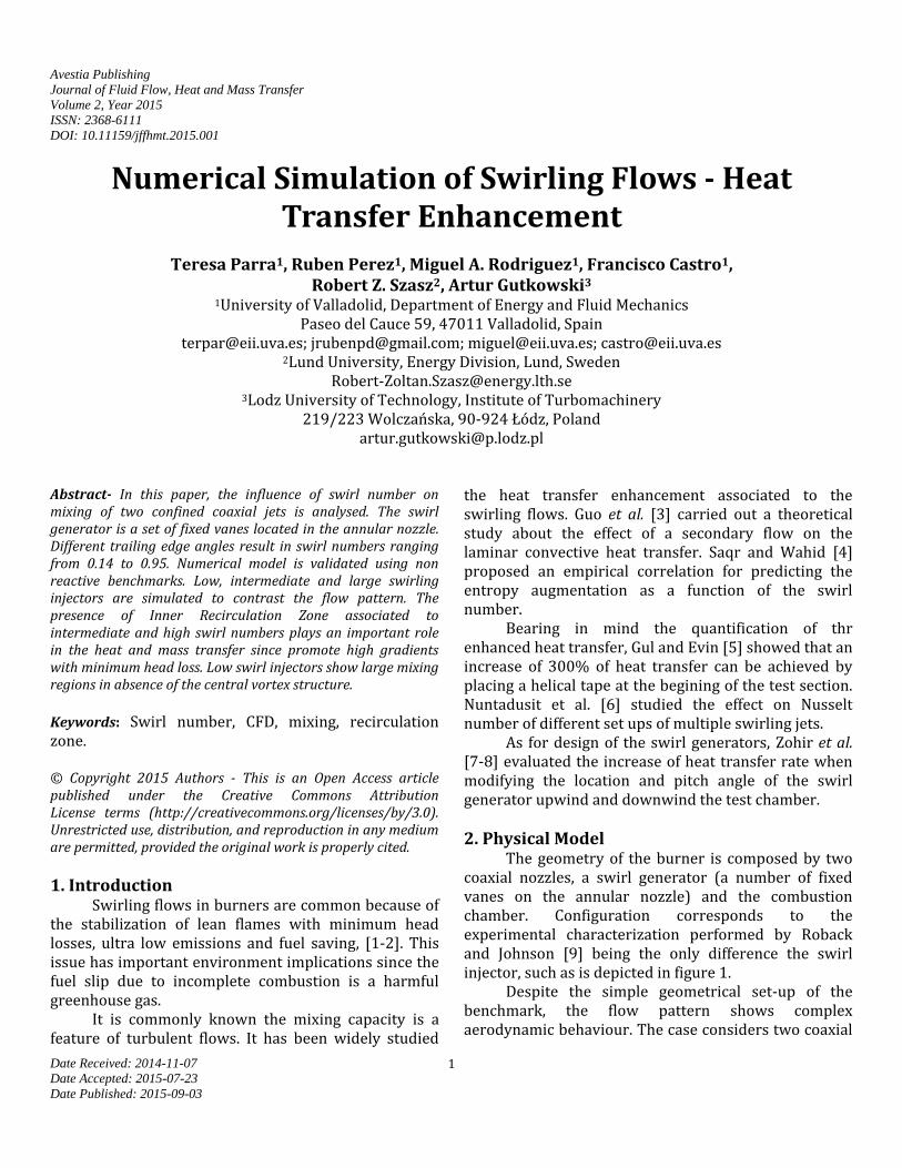
coaxial nozzles, a swirl generator (a number of fixed vanes on the annular nozzle) and the combustion chamber. Configuration corresponds to the experimental characterization performed by Roback and Johnson [9] being the only difference the swirl injector, such as is depicted in figure 1.
Despite the simple geometrical set-up of the benchmark, the flow pattern shows complex aerodynamic behaviour. The case considers two coaxial
2
jets: one axial and another annular swirling jet. An expansion ratio of 4 in area produces the Outer Recirculation Zone (ORZ) when annular jet enters in the chamber. This kind of configuration has been analyzed by Palm [10] for swirl numbers 0, 0.6 and 1.2.
Main difference in flow pattern between low and large swirling injectors is the presence of an expansion or a recirculation in the centre of the chamber. If swirl number is over 0.6, the flow turns back into the centre and then vortex break down phenomenon appears to form an Inner Recirculation Zone (IRZ), [11]. Both recirculation zones are responsible of high shear and mixture. If swirl number is lower, there is an Inner Divergence Zone instead of the IRZ.
Figure 1. Scheme of the swirling burner of Roback and
Johnson [9] with swirler angle 64º and detail of the hexahedral mesh.
Computational Fluid Dynamics (CFD) has become
a useful tool to gain insight of the phenomena involved in thermal and fluid mechanics processes. The simulation requests the generation of a mesh that is a discretization of a continuous geometry into a computational domain. The finite volume Ansys-Fluent was used to carry out the simulations.
The selection of numerical methods is a prerequisite to perform accurate numerical simulations to better predict the performance of the swirling flow burner.
3. Numerical Model The conservative equations for 3D, steady,
turbulent and incompressible flow are solved with a second order scheme looking for better accuracy. Table 1 summarizes the boundary conditions for the nozzle
inlets working with air. Passive scalar let identify the mixture fraction associated to the inner jet. As for length scale the hydraulic diameter was considered. Main uncertainty is the transitional flow regime. The 3D mesh has 1.5 million hexahedral cells. The sensibility analysis of mesh resolution revealed that RANS models provide velocity profiles that were independent from meshes for more than 1.5 million cells. Meshes with 0.5, 0.75 1, 1.5 and 2 million cells were tested, as described in [12].
PISO was the algorithm for pressure-velocity coupling since the option provides faster convergence. Multigrid options provide a substantial reduction of the computational time. It consists on solving equations on a coarse mesh to get initial solution to iterate on a finer mesh. However, multigrid is not suitable for reactive cases because the averaging on temperature field is a precursor of the lack of accuracy on the reaction rate. Parallel processing is important to afford resolution of meshes with adequate spatial resolution. The domain decomposition process was established to minimize the processor boundaries and therefore, saving information transfer time.
Table 1. Boundary conditions for nozzles from reference [9].
Annular inlet Central inlet Radio (inner-outer) (m)
4. Turbulence Model As for the turbulence model, among RANS models
of 1, 2 or 4 equations, the most accurate was the k-ε RNG model dominated by the swirl. It is recommended by Ferziger [13-14] to deal with the non-isotropic turbulence associated with the swirling.
The conservation equations for the k and ε are represented in the RNG model as:
𝜕
𝜕𝑥𝑖(𝜌𝑘𝑢𝑖) =
𝜕
𝜕𝑥𝑗(𝛼𝑘𝜇𝑒𝑓𝑓
𝜕𝑘
𝜕𝑥𝑗) + 𝐺𝑘 − 𝜌𝜀 (1)
𝜕
𝜕𝑥𝑖(𝜌𝜀𝑢𝑖) =
𝜕
𝜕𝑥𝑗(𝛼𝜀𝜇𝑒𝑓𝑓
𝜕𝜀
𝜕𝑥𝑗) (2)
+𝐶1𝜀𝜀
𝑘𝐺𝑘 − 𝐶2𝜀𝜌
𝜀2
𝑘− 𝑅𝜀
3
being
𝑅𝜀 =𝐶𝜇𝜂
3𝜌(1−𝜂 𝜂0⁄ )
1+𝛽𝜂3𝜀2
𝑘 (3)
and
𝜂 = (2𝑆𝑖𝑗𝑆𝑖𝑗)0.5
𝑘 𝜀⁄ (4)
Where k is the turbulent kinetic energy and ε its
corresponding dissipation, u denotes the averaged velocities and the density.
The source term Rε in equation 2, represents the rate of strain defined in equations (3) and (4). Where S is the strain tensor calculated based on averaged velocities.
The coefficients are summarized in table 2. Table 2. Constants in the RNG k-ε model.
C C1ε C2ε 0
0.0845 1.42 1.68 4.38 0.012
Bearing in mind the flow pattern is dominated by
recirculation zones and fluid separation of the boundaries, the turbulence wall treatment was that of non equilibrium, hence it is not necessary to control the y+ range of variation.
5. Swirl Generator Swirl generator is characterized by eight- fixed
vanes in the annular nozzle with a fix angle in the trailing edge, Parra et al. [15]. The definition assumed for the swirl number is the relation between the flow-averaged-azimuthal velocity and the corresponding axial velocity, see equation 5.
Table 3. Details of different set up of swirl injectors. Design Flat plate Curved blade Flat plate Chord 50 mm 50 mm 25 mm Swirler Angle 22º 54º 64º Swirl number 0.14 0.74 0.95
𝑆 =∫ 𝜌𝑟𝑣𝜃𝑣𝑧2𝜋𝑟𝑑𝑟
𝑅∫ 𝜌𝑣𝑧22𝜋𝑟𝑑𝑟
(5)
Hence different swirl numbers request different
orientation for the vanes. Previous studies have verified the lack of influence of the swirler's chord on the swirl
number as well as the weak influence of the design (flat plates or curved blades) on the final flow pattern. Table 3 shows the different swirler configurations presented in this paper to provide different swirl numbers.
6. Influence of Swirl Number This section is devoted to the analysis of the flow
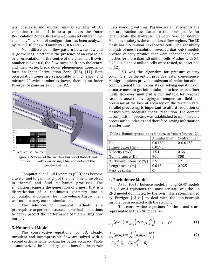
pattern associated to low and high swirl numbers. Figure 2 shows, for non-reactive case and swirl
numbers of 0.14, 0.74 and 0.95, the contours of temperature in a longitudinal plane and the volumes of iso-value null for axial velocity. Annular jet has a temperature of 900 K whereas central jet has 300 K; hence temperature gradient suggests the mixing.
Besides, the zero axial velocity surfaces identify the position, shape and size of recirculation zones. Bearing in mind the ORZ that is formed due to the sudden expansion in the discharge of the annular nozzle [16], it has a diminishing in size while increasing the swirl number. This statement agrees with other research works [17].
Swirl number 0.74 shows an incipient IRZ while Swirl number 0.95 shows a larger IRZ. The IRZ forces the mixing; hence temperature is homogenized very close to the nozzle's discharge. This means that temperature is homogenized in more remote sections of the nozzle's discharge in the cases with low azimuthal velocity.
Figure 2. Contours of temperature in the plane x = 0 and iso-
surfaces of null axial velocity to locate recirculation zones. Left) Swirl no. 0.14, Center) Swirl no. 0.74 and Right) Swirl
no. 0.95.
Furthermore, the shape of the IRZ in the
upstream stagnation point is convex for swirl number 0.74 and concave for swirl number 0.95 increasing significant effect on heat transfer for larger swirls such it was showed in [18].
4
IRZ plays an essential role in homogenizing temperature. Because of the IRZ, the shear layer is deflected. The bigger the IRZ is, the thinner the shear layer is. Hence higher gradient appears. Another aspect is that the upwind stagnation point of the IRZ is approaching the discharge of the central nozzle while increasing the swirl number; hence the mixing region is small.
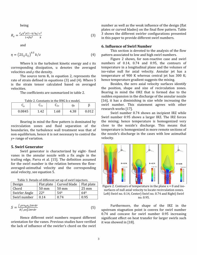
Figure 3. Radial profiles of axial velocities for different
sections. Upper Left) Z = 5mm, Lower Left) Z = 25mm, Upper Right) Z = 50mm and Lower Right) Z = 100mm Experimental
values of Palm et al. [10].
Figure 4. Radial profiles of Temperature for different
sections. Upper Left) Z = 5mm, Lower Left) Z = 50mm, Upper Right) Z = 100mm and Lower Right) Z = 300mm.
Figure 3 shows the radial profiles of axial velocity
for Swirl numbers 0.14, 0.64 and 0.74 in different cross sections located at Z = 5, 25, 50 and 100 mm from the discharge of the nozzles as well as the experimental results from Palm et al. [10]. These experimental results are for a swirl of 0.6. Every section evidences the increase of momentum mixing while increasing the
swirl. The sections Z = 5 mm, 25 and 50 mm show that the numerical results are less dissipative than experimental results but section Z = 100 mm section shows a good agreement with the experimental results. Negative values of the axial velocity evidence the existence of recirculation zones. It is clear the presence of ORZ in sections 25 and 50 mm for any swirl. As for the IRZ, it only appears for Swirl 0.74.
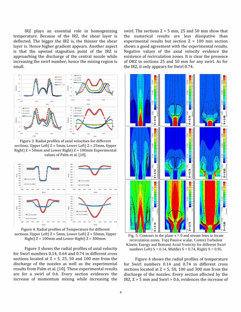
Fig. 5. Contours in the plane x = 0 and stream lines to locate
Kinetic Energy and Bottom) Axial Vorticity for different Swirl
numbers Left) S = 0.14, Middle) S = 0.74, Right) S = 0.95.
Figure 4 shows the radial profiles of temperature
for Swirl numbers 0.14 and 0.74 in different cross sections located at Z = 5, 50, 100 and 300 mm from the discharge of the nozzles. Every section affected by the IRZ, Z > 5 mm and Swirl > 0.6, evidences the increase of
-0.5
0
0.5
1
1.5
2
2.5
-0.07 -0.02 0.03
S=0.14
S=0.64
S=0.74
Palm S = 0.6
Vz
[m/s
]
r [m]
-0.5
0
0.5
1
1.5
2
-0.07 -0.02 0.03
S=0.14
S=0.64
S=0.74
Palm S=0.6
Vz
[m/s
]
r [m]
-1
-0.5
0
0.5
1
1.5
2
-0.07 -0.02 0.03
S=0.14
S=0.64
S=0.74
Palm S=0.6
Vz
[m/s
]
r [m]
-0.4
-0.2
0
0.2
0.4
0.6
0.8
1
1.2
1.4
-0.07 -0.02 0.03
S=0.14
S=0.64
S=0.74
Palm S=0.6
r [m]
Vz
[m/s
]
0
100
200
300
400
500
600
700
800
900
1000
-0.08 -0.06 -0.04 -0.02 0 0.02 0.04 0.06 0.08
S=0.14 noRXN
S=0.74 noRXN
Tª[ K
]
R [m]
Tª[ K
]
R [m]
0
100
200
300
400
500
600
700
800
900
1000
-0.08 -0.06 -0.04 -0.02 0 0.02 0.04 0.06 0.08
S=0.14 noRXN
S=0.74 noRXN
Tª[ K
]
R [m]
Tª[ K
]
R [m]
0
100
200
300
400
500
600
700
800
900
-0.08 -0.06 -0.04 -0.02 0 0.02 0.04 0.06 0.08
S=0.14 noRXN
S=0.74 noRXN
Tª[ K
]
R [m]
Tª[ K
]
R [m]
720
722
724
726
728
730
732
734
736
738
740
-0.08 -0.06 -0.04 -0.02 0 0.02 0.04 0.06 0.08
S=0.14 noRXN
S=0.74 noRXN
Tª[ K
]
R [m]
Tª[ K
]
R [m]
5
heat transfer while increasing the swirl. Mass fraction shows similar results in the same sections. It is clear the homogenization role played by the IRZ for high swirl numbers.
Figure 5 show longitudinal contours of the passive scalar, turbulent kinetic energy and axial vorticity. The first one let identify mass mixing. Steam lines let identify the IRZ concluding the important role played in homogenizing species. Turbulent kinetic energy show maximum values on the shear layer but there is not relevant production of energy inside the IRZ. Finally, the axial vorticity is located on the annular jet because of the swirler and in the IRZ, where fluid spin as a rigid solid, with minimum deformation.
7. Conclusion This paper studies the mixing of different swirling
jets ranging from low to intermediate and high swirling numbers. Validation was provided for high swirl number.
Low swirling injectors does not promote the fluid to turn over near the centre of the chamber, resulting larger mixing zones with weak gradients. Pressure distribution for intermediate and larger swirls promote the formation of a vortex bulb near the axis of the chamber. This inner recirculation zone is responsible of deflecting the shear layer and increases the gradients near the upstream of its lead stagnation point. As a result, mixing occurs at short distance of the nozzle's discharge. Therefore it is justified the common use of swirling to burn lean mixtures that would show instable behaviour without any swirl.
Also the convex or concave shape of the recirculation point near this stagnation point is significant on the mass and heat transfer. The former appears for Swirl number 0.74 whereas the latest appears for Swirl = 0.95. Future works involve the study of reactive cases.
8. Acknowledgements The authors thankfully acknowledge the Spanish
Ministry of Science and Innovation for the financial resources in the framework of the project reference ENE2011-25468.
We acknowledge PRACE for awarding us access to resource Curie-Genci based in France at CEA and MareNostrum based in Spain at BSC. Ref. 2010PA1766.
References [1] T. Parra, R. Z. Szasz, C. Duwig, R. Pérez, V. Mendoza and F. Castro, “Acoustic Instabilities on Swirling
Flames,” International Journal of Mechanical Engineering, vol. 7, no. 9, pp. 742-745, 2013. [2] H. S. Zhen, C. S. Cheung, C.W. Leung and H.B. Li, "Thermal and heat transfer behaviors of an inverse diffusion flame with induced swirl," Fuel, vol. 103, pp. 212–219, 2013. [3] J. Guo, Y. Yan, W. Liu, F. Jiang and A. Fan, "Enhancement of laminar convective heat transfer relying on excitation of transverse secondary swirl flow," International Journal of Thermal Sciences, vol. 87, pp. 199-206, 2015. [4] K. M. Saqr and M. A. Wahid, "Effects of swirl intensity on heat transfer and entropy generation in turbulent decaying swirl flow," Applied Thermal Engineering, vol. 70, pp. 486-493, 2014. [5] H. Gül and D. Evin, "Heat transfer enhancement in circular tubes using helical swirl generator insert at the entrance," International Journal of Thermal Sciences, vol. 46, pp. 1297–1303, 2007. [6] C. Nuntadusit, M. Wae-hayee, A. Bunyajitradulya and S. Eiamsa-ard, "Heat transfer enhancement by multiple swirling impinging jets with twisted-tape swirl generators," International Communications in Heat and Mass Transfer, vol. 39, pp. 102–107, 2012. [7] A.E. Zohir and A.G. Gomaa, "Heat transfer enhancement through sudden expansion pipe airflow using swirl generator with different angles," Experimental Thermal and Fluid Science, vol. 45, pp. 146-154, 2013. [8] A.E. Zohir, A.A. Abdel Aziz and M.A. Habib, "Heat transfer characteristics in a sudden expansion pipe equipped with swirl generators," International Journal of Heat and Fluid Flow, vol. 32, pp. 352–361, 2011. [9] R. Roback and B.V. Johnson, "Mass and momentum turbulent transport experiments with confined swirling coaxial jets," Interim Report, 1983. [10] R. Palm, S. Grundmann, M. Weismuller, S. Saric, S. Jakirlic and C. Tropea, "Experimental characterization and modelling of inflow conditions for a gas turbine swirl combustor," International Journal of Heat and Fluid Flow, vol. 27, pp. 924–936, 2006. [11] T. Parra-Santos, J. R. Perez-Dominguez, R. Z. Szasz and F. Castro, Engineering Computations. Accepted 23.07.2014. [12] T. Parra-Santos, J. R. Perez-Dominguez, R.Z. Szasz and F. Castro, “An isothermal analysis of curved-vane
6
and flat-vane swirlers for burners,” Engineering Computations, vol. 32, no. 3, pp. 668-686, 2015. [13] J. H. Ferziger and M. Peric, Computational Methods for Fluid Dynamics, 3rd edition, Springer, 2002.
[14] H. K. Versteeg and W. Malalasekera, An Introduction to Computational Fluid Dynamics, The Finite Volume Method, Longman Group Ltd, 1995. [15] T. Parra, V. Vuorinen, R. Perez, R. Szasz and F. Castro, "Aerodynamic characterization of isothermal swirling flows in combustors," International Journal of Energy and Environmental Engineering, vol. 5, no. 2, pp. 1-6, 2014.
[16] V. Yakhot, S. A. Orszag, S. Thangam, T. B. Gatski and C. G. Speziale, "Development of turbulence models for shear flows by a double expansion technique," Physics of Fluids A, vol.4, no. 7, pp. 1510-1520, 1992.
[17] M.García-Villalba and J.Fröhlich, "LES of a free annular swirling jet–Dependence of coherent structures on a pilot jet and the level of swirl," International journal of heat and fluid flow, vol. 27, no. 5, pp. 911-923, 2006. [18] T. Parra, R. Perez, G. Lorenzo, R. Szasz, A. Gutkowski and F. Castro, "Diffuser influence on the mixing of coaxial swirling jets," ASME FEDSM2014‐21354, 2014.