12 th International Research/Expert Conference ”Trends in the Development of Machinery and Associated Technology” TMT 2008, Istanbul, Turkey, 26-30 August, 2008 NUMERICAL STRESS AND STRAIN ANALYSIS OF VERTICAL CYLINDRICAL TANK Fadil Islamović Technical Faculty University of Bihać, Bihać Bosnia and Herzegovina Pašaga Muratović Faculty of Mechanical Engineering University of Tuzla, Tuzla Bosnia and Herzegovina Džafer Kudumović Faculty of Mechanical Engineering University of Tuzla, Tuzla Bosnia and Herzegovina ABSTRACT: The calculation of cylindrical tank rebuilt by four separated vertical chambers, as well as stress- strain analysis, were performed by using finite element method through software package NASTRAN. In paper are especially defined combined T details and welded joint angle for critical nodel points of floor, jacket and blocks welded joint, thus giving numerical stress and strain analysis results for all applied welding technologies. Keywords: tank, strain, stress, welding, numerical model, numerical analysis. 1. INTRODUCTION 5000 m 3 capacity cylindrical tank made of S.0361 steel is designed for storing petroleum products and specific weight petroleum up to 1000 kg/m 3 . Internal diameter of tank is 24384 mm. Height, measured from bottom of tank to internal surface of boundary angle arm, is 11010 mm. These dimensions enable tank to accept 5000 tons of useful load [1]. Schematic illustration of multi-chambered cylindrical tank is given in Picture 1. Picture 1. Multi-chambered cylindrical tank 1257
Transcript
12th International Research/Expert Conference ”Trends in the Development of Machinery and Associated Technology”
TMT 2008, Istanbul, Turkey, 26-30 August, 2008
NUMERICAL STRESS AND STRAIN ANALYSIS OF VERTICAL CYLINDRICAL TANK
Fadil Islamović Technical Faculty
University of Bihać, Bihać Bosnia and Herzegovina
Pašaga Muratović
Faculty of Mechanical EngineeringUniversity of Tuzla, Tuzla Bosnia and Herzegovina
Džafer Kudumović Faculty of Mechanical Engineering
University of Tuzla, Tuzla Bosnia and Herzegovina
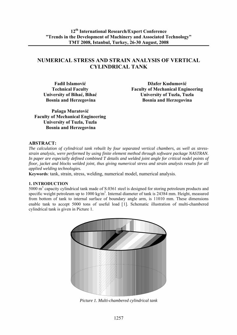
ABSTRACT: The calculation of cylindrical tank rebuilt by four separated vertical chambers, as well as stress-strain analysis, were performed by using finite element method through software package NASTRAN. In paper are especially defined combined T details and welded joint angle for critical nodel points of floor, jacket and blocks welded joint, thus giving numerical stress and strain analysis results for all applied welding technologies. Keywords: tank, strain, stress, welding, numerical model, numerical analysis. 1. INTRODUCTION 5000 m3 capacity cylindrical tank made of S.0361 steel is designed for storing petroleum products and specific weight petroleum up to 1000 kg/m3. Internal diameter of tank is 24384 mm. Height, measured from bottom of tank to internal surface of boundary angle arm, is 11010 mm. These dimensions enable tank to accept 5000 tons of useful load [1]. Schematic illustration of multi-chambered cylindrical tank is given in Picture 1.
Picture 1. Multi-chambered cylindrical tank
1257
2. NUMERIC STRESS AND STRAIN ANALYSIS OF JACKET AND PARTITION The starting numeric model of petroleum multi-chambered tank is defined by choice of shape and dimensions of 5000 m3 capacity cylindrical tank [2]. Picture 2 shows overall image of 5000 m3 capacity tank.
Picture 3. Model with horizontal and vertical partitions
different chambers, as well as analysis of stress-ite elements method through software package odel testing, linear static analysis was used during
according to previous researches and testing [4], t the highest overload points. lindrical tank presented by finite element model in Picture 3
sheets) are idealized by shell
lements (accepts membrane and bending load). ion walls
s accepts all types of ads (all forces and moments).
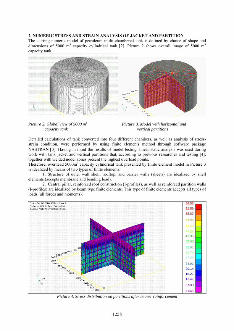
Picture 2. Global view of 5000 m3 capacity tank Detailed calculations of tank converted into four strain condition, were performed by using finNASTRAN [3]. Having in mind the results of mwork with tank jacket and vertical partitions that, together with welded nodel zones presenTherefore, overhead 5000m3 capacity cyis idealized by means of two types of finite elements:
1. Structure of outer wall shell, rooftop, and barrier walls (e
2. Central pillar, reinforced roof construction (I-profiles), as well as reinforced partit(I-profiles) are idealized by beam type finite elements. This type of finite elementlo
4.665
8.533
66.5662.5958.83
54.96
47.22
39.58
27.88
24.0120.1416.2712.41
51.09
43.35
35.6131.74
Picture 4. Stress distribution on partitions after bearer reinforcement
1258
By introducing hydrostatic pressure we analyzed the case of loading when two opposite chambers are filled with liquid (ρ = 1000 kg/m3), while two other chambers are empty.carried out in my master’s thesis, where I did not know whether stress levels and displacements inpartitions without reinforcement would be so high, this research ststiffening of partition sheets, profiles were positioned for reinforced structures.
In order to overcome the problem and move tank partitions into permioverhead cylindrical tank model was horizontally and vertically reinforced with 8bearers we used standard I profiles type I 32, Picture 4 (Stress distribution bearer reinforcement). The same bearers were idealized with beam type of finite e
According to Picture 5, stress condition on vertical tank jacket is satisfying, levels range in between 120 and 140 MPa.
By analyzing results of previous research [4], it is notable that in nodal point zone of floor, jacket, and partition welded joint stress values reached enormously high level that range up to levels are a consequence of liquid absence in neighbouring chambers bending rigidity in partition connection zone, where jacket is exposed to
Compared to research
arted with postulation that, for
ssible stress zone, general
x 7 bearers. As across partitions after
lements.
since maximum stress
255 MPa. These and relatively low jacket
bending strain. Additionally, these
high thstress levels are a consequence of welding technology at was not properl
fic conditions. y
chosen for speci
9,797
17,91
139.8131.7
.2191,14
74,78
26,04
123.5
115.4
107.3
99
82,91
66,6558,55
50,4242,2934,17
Picture 5. Stress distribution across tank jacket after bearer reinforcement Jacket and partition connection zone needs to be additionally reinforced on partition and jacket part in order to reduce bending strain, and perform testing of all cases with numeric model. 3. NUMERIC STRESS AND STRAIN ANALYSIS OF NODEL POINTS Having in mind aforesaid, critical nodel point detail has been defined, i.e. T combination and welded joint angle detail for all four applied welding technologies. Picture 6 shows reinforced partitions and details with stress condition distribution in nodel zone for Technology A, Picture 7 for Technology B, while Pictures for Technologies C and D were omitted due to limited space in this paper.
1259
19.23
23.12
81.5577.3673.31
69.30
67.28
63.2559.2255.20
51.1747.1643.14
39,1135.0631.0227.01
Picture 6. Nodel point critical zone detail for Technology A
11 .83
15 .69
27 .2523 .3819 .52
72 .4668 .5964 .69
60 .82
56 .93
45 .41
534 .96
31 .08
53.0949 .24
41 .6437 .8
Picture 7. Nodel point critical zone detail for Technology B 4. CONCLUSION Correction of numeric model, by introducing additional reinforcement for the purpose of lowering bending strain, resulted in fact that, according to defined model, maximum stress levels in average do not go above 85 MPa. The optimum condition, i.e. the lowest stress values were registered in applied welding technology B (72, 46 MPa), what was expected, having in mind all previous research results [4]. It should be noted that complete analysis and calculation are treating one or two opposite tank parts, which is the most critical point. Solution, that was in basic technical sense performed by ‘’NASTRAN’’ program (reinforcement of partitions was performed with standard I profiles type I32 with 8 x 7 fields), is no doubt one of possible high-quality tank solutions. 5. REFERENCES [1] Chief mechanical project of 5000m3 capacity R-5 tank, TTT S-105 Bihać, (VI/1975). [2] Isla ović F.: Integrity advancement of fixed multi-chambered thin-walled essels for liquid fuels,
Do oral dissertation, Faculty of Mechanical Engineering Tuzla, 2006. [3] MSC/NASTRAN for constructions and
construction elements, 2002. [4] Islamović F., ″ Proceeding for algorithm design development of overhead multi-chambered vessels for
liquid fuels″, Master’s Thesis, Zenica, 2001.
m vct
- Program for numeric stress and strain analysis conditions