Network Verified Architecture VMware Validated Design for NetApp HCI VVD 4.2 Architecture Design Sean Howard, NetApp May 2019 | NVA-1128-DESIGN | Version 1.1 Abstract This document describes the high-level design criteria for a VMware Validated Design (VVD, version 4.2) using VMware cloud-enablement products layered on top of NetApp ® HCI components.
Transcript
Network Verified Architecture
VMware Validated Design for NetApp HCI VVD 4.2 Architecture Design
Sean Howard, NetApp
May 2019 | NVA-1128-DESIGN | Version 1.1
Abstract
This document describes the high-level design criteria for a VMware Validated Design
(VVD, version 4.2) using VMware cloud-enablement products layered on top of NetApp®
3.6 Business Continuity Layer............................................................................................................................. 13
3.12 Availability Zones and Regions ..................................................................................................................... 20
12.2 vRealize Business for Cloud Design ........................................................................................................... 213
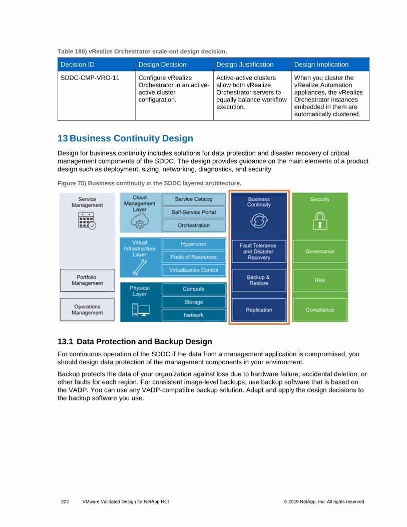
13 Business Continuity Design ............................................................................................................ 222
13.1 Data Protection and Backup Design ........................................................................................................... 222
13.2 Site Recovery Manager and vSphere Replication Design .......................................................................... 227
Where to Find Additional Information .................................................................................................. 242
Version History ....................................................................................................................................... 242
LIST OF TABLES
Table 1) Benefits and drawbacks of layer 2 transport. ................................................................................................. 16
Table 2) Benefits and drawbacks for layer 3 transport. ................................................................................................ 17
Table 3) Installation models of vSphere Update Manager and Update Manager Download Service. .......................... 35
Table 4) Region identifiers. ........................................................................................................................................... 47
Table 5) Availability zones and region design decisions. ............................................................................................. 47
Table 6) Cluster and racks design decisions. ............................................................................................................... 49
Table 7) Compute node model selection. ..................................................................................................................... 51
Table 10) Sample values for VLANs and IP ranges. .................................................................................................... 53
Table 39) Virtual switch for the management cluster. ................................................................................................... 85
Table 40) vDS-MgmtPort Group configuration settings. ............................................................................................... 85
Table 41) Management virtual switches by physical/virtual NIC. .................................................................................. 86
Table 42) Management virtual switch port groups and VLANs. .................................................................................... 86
Table 54) NIC teaming and policy. ............................................................................................................................... 93
Table 55) NIC teaming design decision. ....................................................................................................................... 94
Table 56) Network I/O Control design decisions. ......................................................................................................... 95
Table 68) Transport zone design decisions. ............................................................................................................... 110
Table 69) Routing model design decisions. ................................................................................................................ 112
Table 79) Example IP ranges. .................................................................................................................................... 121
Table 123) Host and cluster settings that are affected by vSphere Update Manager. ................................................ 177
Table 124) Host and cluster settings for updates. ...................................................................................................... 178
Table 125) vSphere Update Manager settings for remediation of virtual machines and appliances. ......................... 178
Table 126) Baselines and baseline groups details. .................................................................................................... 179
Table 134) vRealize Automation IaaS web server design decision. ........................................................................... 189
Table 135) vRealize Automation IaaS web server resource requirements. ................................................................ 189
Table 136) vRealize Automation IaaS Model Manager and DEM Orchestrator server design decision. .................... 190
Table 137) vRealize Automation IaaS Model Manager and DEM Orchestrator server resource requirements per virtual machine. .......................................................................................................................................................... 190
Table 153) Base Windows Server requirements and standards. ................................................................................ 201
Table 154) Base Windows Server blueprint sizing. .................................................................................................... 202
Table 155) Base Linux Server requirements and standards....................................................................................... 202
Table 156) Base Linux Server blueprint sizing. .......................................................................................................... 203
Table 157) Base Windows Server with SQL Server installation requirements and standards. ................................... 203
Table 158) Base Windows Server with SQL Server blueprint sizing. ......................................................................... 203
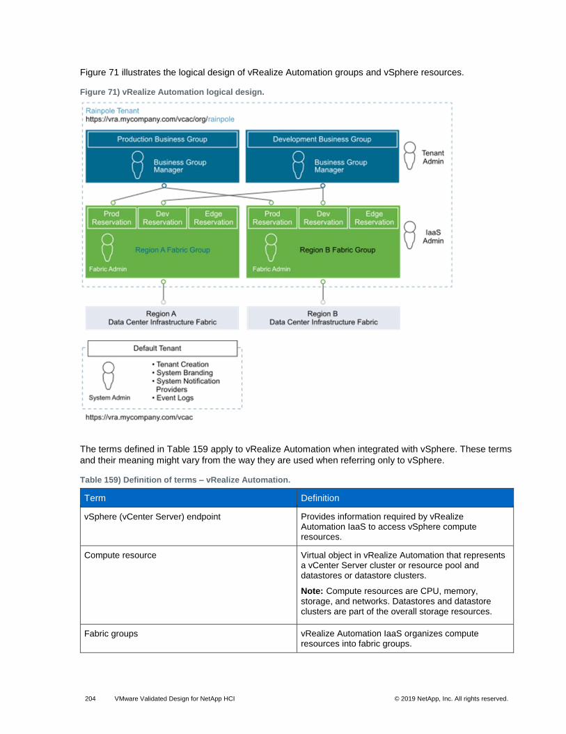
Table 159) Definition of terms – vRealize Automation. ............................................................................................... 204
Table 186) Authorization and authentication management for a VADP-compatible solution design decisions. ......... 226
Table 187) Component backup jobs design decision. ................................................................................................ 227
Table 188) Logical configuration for disaster recovery in the SDDC. ......................................................................... 227
Table 189) Site Recovery Manager and vSphere replication deployment design decisions. ..................................... 229
Table 190) Compute resources for a Site Recovery Manager node. .......................................................................... 229
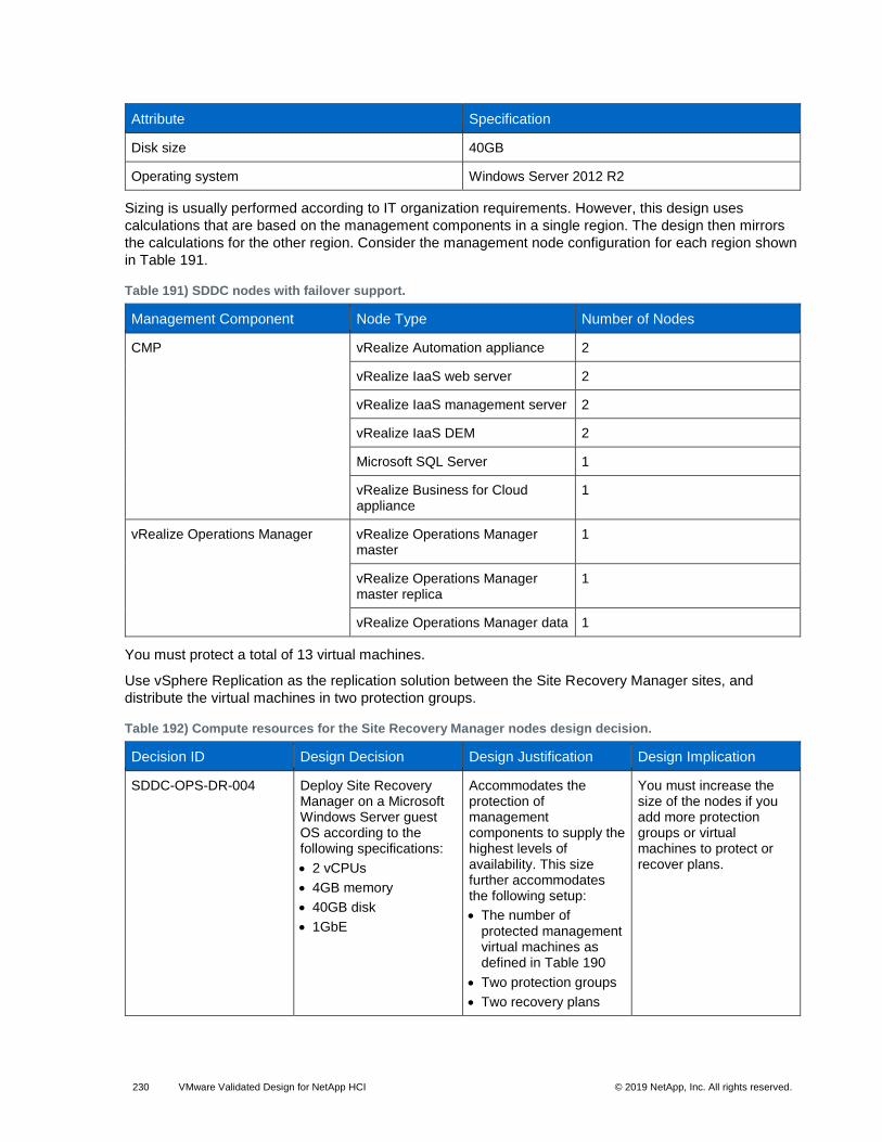
Table 191) SDDC nodes with failover support. ........................................................................................................... 230
Table 192) Compute resources for the Site Recovery Manager nodes design decision. ........................................... 230
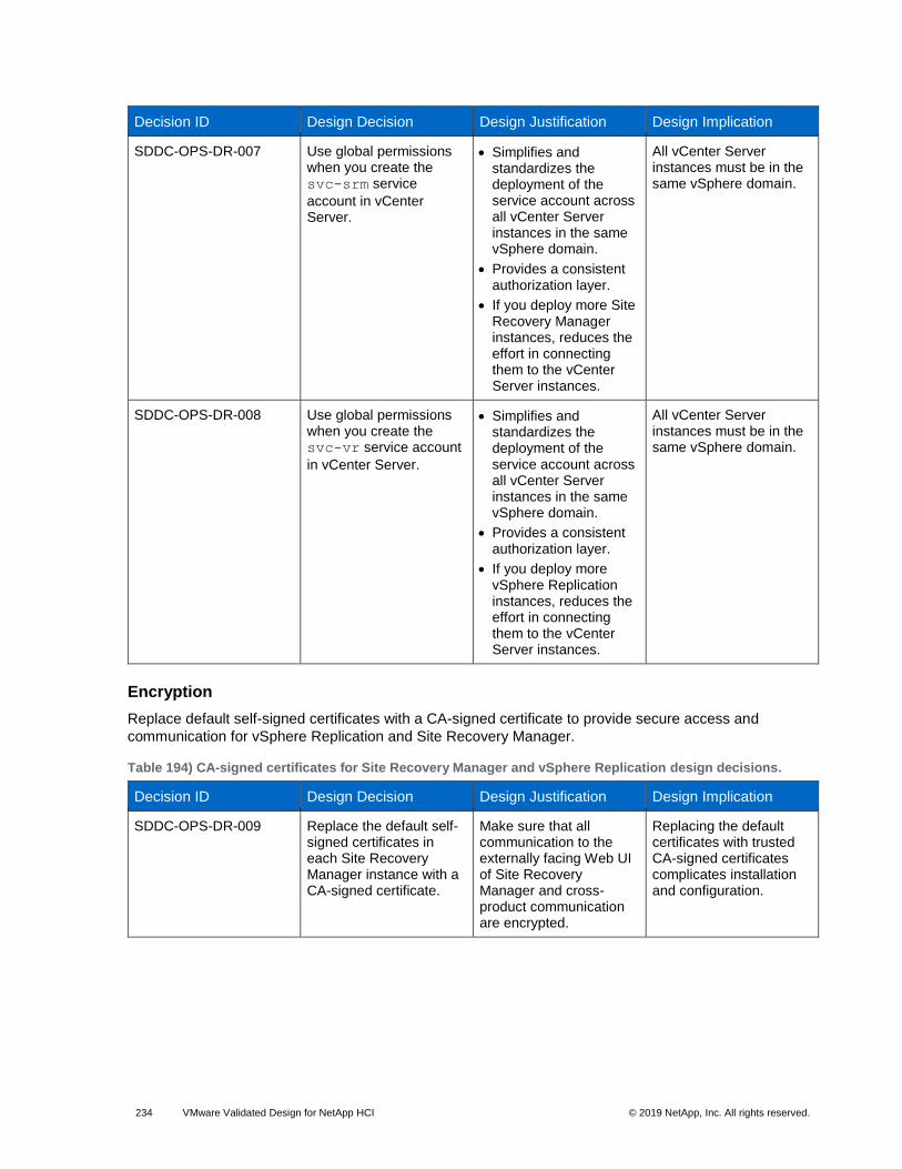
Table 193) Authorization and authentication management for Site Recovery Manager and vSphere Replication design decisions. ........................................................................................................................................................ 233
Table 194) CA-signed certificates for Site Recovery Manager and vSphere Replication design decisions. ............... 234
Figure 3) Clusters in the SDDC. ................................................................................................................................... 15
Figure 4) Example layer 2 transport. ............................................................................................................................ 17
Figure 6) Quality of service trust point. ......................................................................................................................... 19
Figure 7) Availability zones and regions. ...................................................................................................................... 20
Figure 8) Virtual infrastructure layer in the SDDC. ....................................................................................................... 21
Figure 21) vRealize Business for Cloud. ...................................................................................................................... 41
Figure 22) Business continuity layer of the SDDC. ....................................................................................................... 43
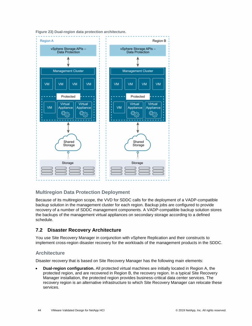
Figure 23) Dual-region data protection architecture. .................................................................................................... 44
Figure 27) Host to ToR connectivity. ............................................................................................................................ 52
Figure 28) Compute and storage nodes installed in H-Series chassis. ........................................................................ 58
Figure 33) Switch port bonding for compute and storage nodes. ................................................................................. 62
Figure 34) Virtual infrastructure layer in the SDDC. ..................................................................................................... 63
Figure 41) Architecture of NSX for vSphere. .............................................................................................................. 100
Figure 43) Cluster design for NSX for vSphere. ......................................................................................................... 108
Figure 44) Logical switch control plane in hybrid mode. ............................................................................................. 110
Figure 45) Virtual application network components and design. ................................................................................ 119
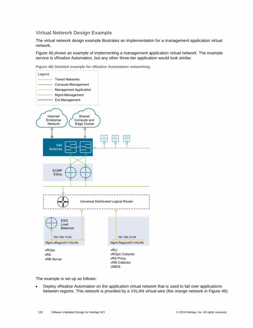
Figure 46) Detailed example for vRealize Automation networking. ............................................................................ 120
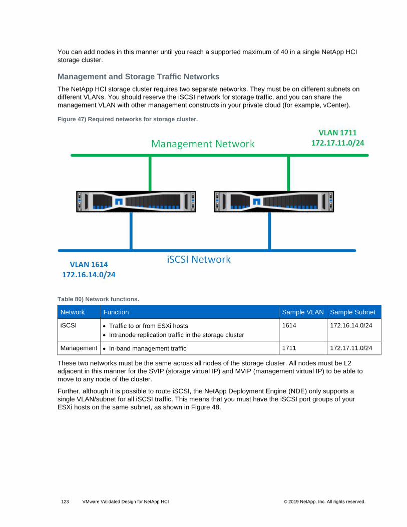
Figure 47) Required networks for storage cluster. ...................................................................................................... 123
Figure 55) Port group iSCSI-A teaming policy. ........................................................................................................... 133
Figure 56) Port group iSCSI-B teaming policy. ........................................................................................................... 133
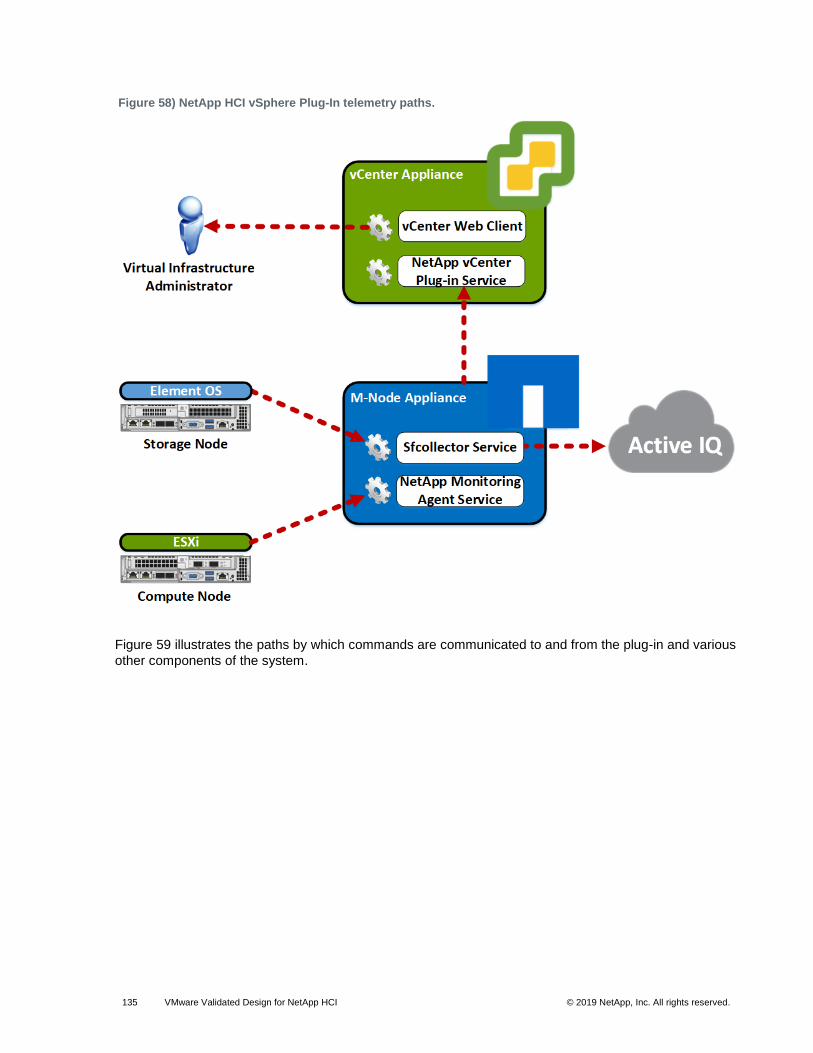
Figure 57) The NetApp Element vCenter Plug-in UI. .................................................................................................. 134
Figure 65) The CMP layer in the SDDC. .................................................................................................................... 181
Figure 68) vRealize Automation design for Region A. ................................................................................................ 186
Figure 69) vRealize Automation design for Region B. ................................................................................................ 187
Figure 70) Example Cloud Automation tenant design for two regions. ....................................................................... 199
Workload domains can include different combinations of servers and network equipment that can be set
up with varying levels of hardware redundancy and component quality. Workload domains are connected
to a network core that distributes data between them. The workload domain is not defined by any physical
properties. Rather, it is a standard unit of connected elements in the SDDC.
A workload domain is a logical boundary of functionality, managed by a single vCenter server, for the
SDDC platform. Although each workload domain typically spans one rack, it is possible to aggregate
multiple workload domains into a single rack in smaller setups. For both small and large setups,
homogeneity and easy replication are important.
Different workload domains of the same type can provide different characteristics for varying
requirements. For example, one virtual infrastructure workload domain could use full hardware
redundancy for each component (power supply through memory chips) for increased availability. At the
same time, another virtual infrastructure workload domain in the same setup could use low-cost hardware
without any hardware redundancy. These variations make the architecture suitable for the different
workload requirements in the SDDC.
Workload Domain-to-Rack Mapping
Workload domains are not mapped one-to-one to data center racks. Although a workload domain is an
atomic unit of a repeatable building block, a rack is merely a unit of size. Because workload domains can
have different sizes, the way workload domains are mapped to data center racks depends on the use
case.
Note: When using a layer 3 network fabric, the management and the shared edge and compute clusters cannot span racks. NSX Controller instances and other virtual machines rely on VLAN-backed networks. The physical network configuration terminates layer 2 networks in each rack at the top-of-rack (ToR) switch. Therefore, you cannot migrate a virtual machine to a different rack because the IP subnet is available only in the rack where the virtual machine currently resides.
• One workload domain in one rack. One workload domain can occupy exactly one rack.
• Multiple workload domains in one rack. Two or more workload domains can occupy a single rack. For example, one management workload domain and one virtual infrastructure workload domain can be deployed to a single rack.
• Single workload domain across multiple racks. A single workload domain can stretch across multiple adjacent racks. For example, a virtual infrastructure workload domain can have more ESXi hosts than a single rack can support.
3.10 Cluster Types
The SDDC differentiates between different types of clusters, including management clusters, compute
clusters, edge clusters, and shared edge and compute clusters.
You can implement the physical layer switch fabric for an SDDC by offering layer 2 or layer 3 transport
services. For a scalable and vendor-neutral data center network, use a layer 3 transport.
This VVD supports both layer 2 and layer 3 transports. When deciding whether to use layer 2 or layer 3,
consider the following:
• NSX equal-cost multipath (ECMP) edge devices establish layer 3 routing adjacency with the first upstream layer 3 device to provide equal-cost routing for management and workload virtual machine traffic.
• The investment you have today in your current physical network infrastructure.
• The following benefits and drawbacks for both layer 2 and layer 3 designs.
Benefits and Drawbacks of Layer 2 Transport
• A design that uses layer 2 transport requires these considerations: In a design that uses layer 2 transport, top-of-rack (ToR) switches and upstream layer 3 devices, such as core switches or routers, form a switched fabric.
• The upstream layer 3 devices terminate each VLAN and provide default gateway functionality.
• Uplinks from the ToR switch to the upstream layer 3 devices are 802.1Q trunks carrying all required VLANs.
Using a layer 2 transport has the benefits and drawbacks described in Table 1.
Table 1) Benefits and drawbacks of layer 2 transport.
Characteristic Description
Benefits • More design freedom.
• You can span VLANs, which can be useful in some circumstances.
Drawbacks • The size of such a deployment is limited because the fabric elements have to share a limited number of VLANs.
• You might have to rely on a specialized data center switching fabric product from a single vendor.
A design using layer 3 transport requires these considerations:
• Layer 2 connectivity is limited in the data center rack up to the ToR switches.
• The ToR switch terminates each VLAN and provides default gateway functionality. That is, it has a switch virtual interface (SVI) for each VLAN.
• Uplinks from the ToR switch to the upstream layer are routed point-to-point links. VLAN trunking on the uplinks is not allowed.
• A dynamic routing protocol, such as OSPF, IS-IS, or the Border Gateway Protocol (BGP), connects the ToR switches and upstream switches. Each ToR switch in the rack advertises a small set of prefixes, typically one per VLAN or subnet. In turn, the ToR switch calculates equal-cost paths to the prefixes it receives from other ToR switches.
Using layer 3 routing has the benefits and drawbacks described in Table 2.
Table 2) Benefits and drawbacks for layer 3 transport.
Characteristic Description
Benefits You can choose from a wide array of layer 3-capable switch products for the physical switching fabric. You can mix switches from different vendors because of the general interoperability between implementation of OSPF, IS-IS, or BGP. This approach is typically more cost effective because it makes use of only the basic functionality of the physical switches.
Drawbacks VLANs are restricted to a single rack. This restriction can affect vSphere fault tolerance and storage networks. To overcome this limitation, use layer 2 bridging in NSX.
The total number of ports available across all switches and the oversubscription that is acceptable
determine the number of racks supported in a fabric. Different racks might host different types of
infrastructure, which can result in different bandwidth requirements.
• Racks with IP storage systems might receive or source more traffic than other racks.
• Compute racks, such as racks hosting hypervisors with virtual machines, might have different bandwidth requirements than shared edge and compute racks, which provide connectivity to the outside world.
Link speed and the number of links vary to satisfy different bandwidth demands. You can vary them for
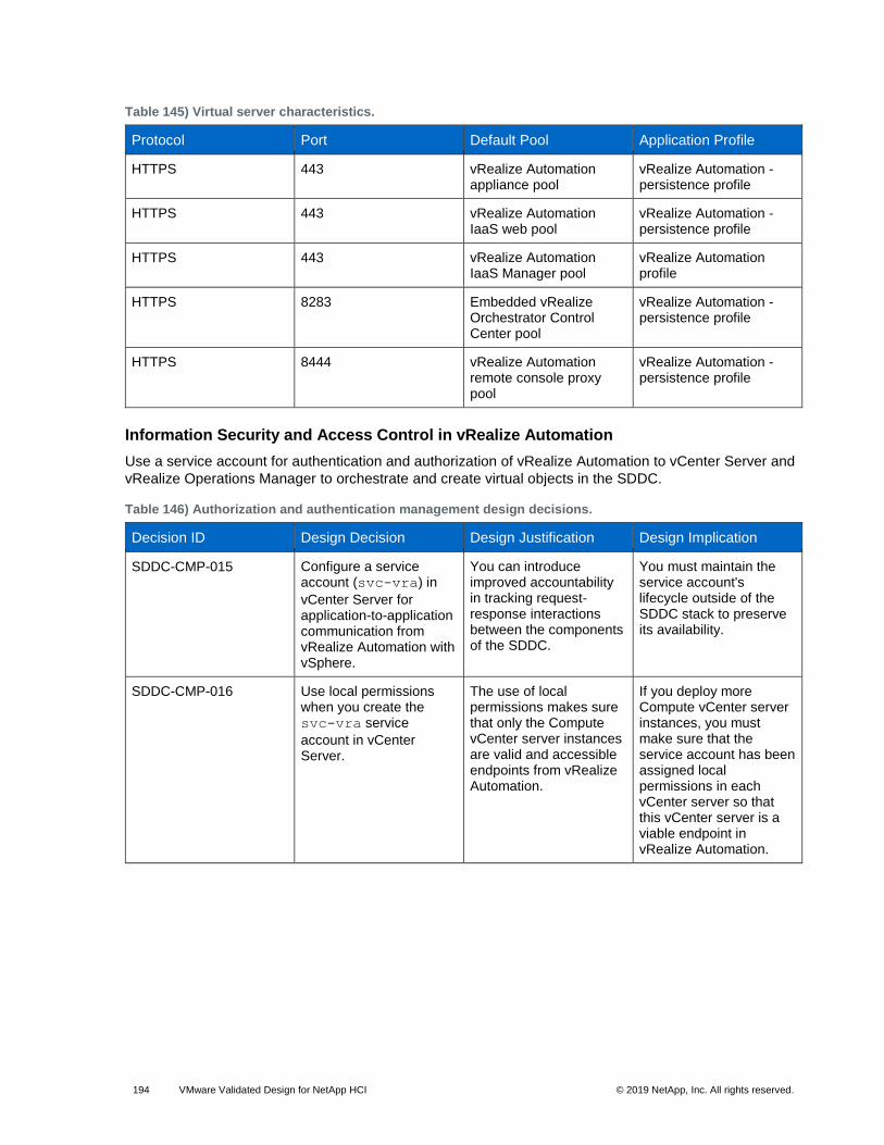
each rack.
Quality of Service Differentiation
Virtualized environments carry different types of traffic, including tenant, storage, and management traffic,
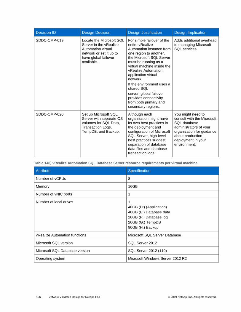
across the switching infrastructure. Each traffic type has different characteristics and makes different
demands on the physical switching infrastructure.
• Management traffic, although typically low in volume, is critical for controlling the physical and virtual network state.
• IP storage traffic is typically high in volume and generally stays within a data center.
For virtualized environments, the hypervisor sets the QoS values for the different traffic types. The
physical switching infrastructure must trust the values set by the hypervisor. No reclassification is
necessary at the server-facing port of a top-of-rack switch. If there is a congestion point in the physical
switching infrastructure, the QoS values determine how the physical network sequences, prioritizes, or
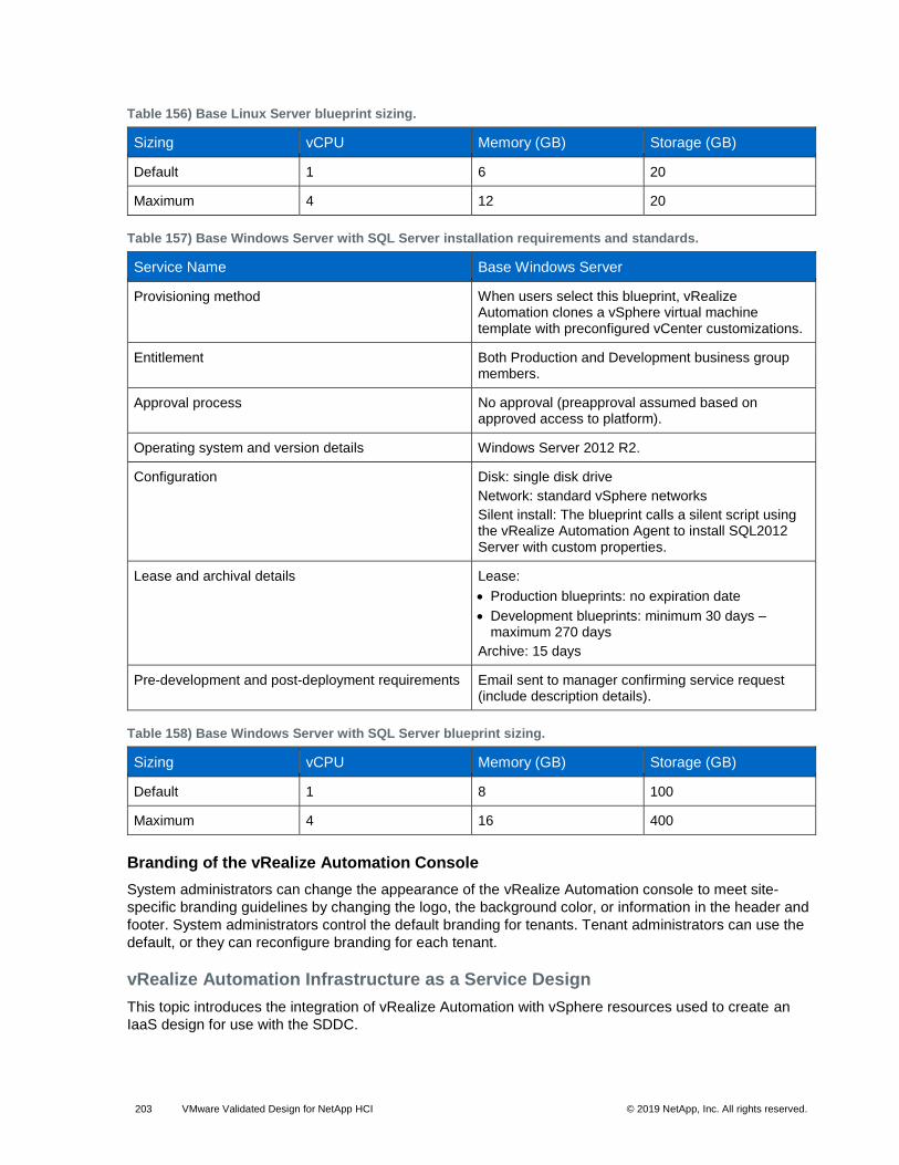
potentially drops traffic.
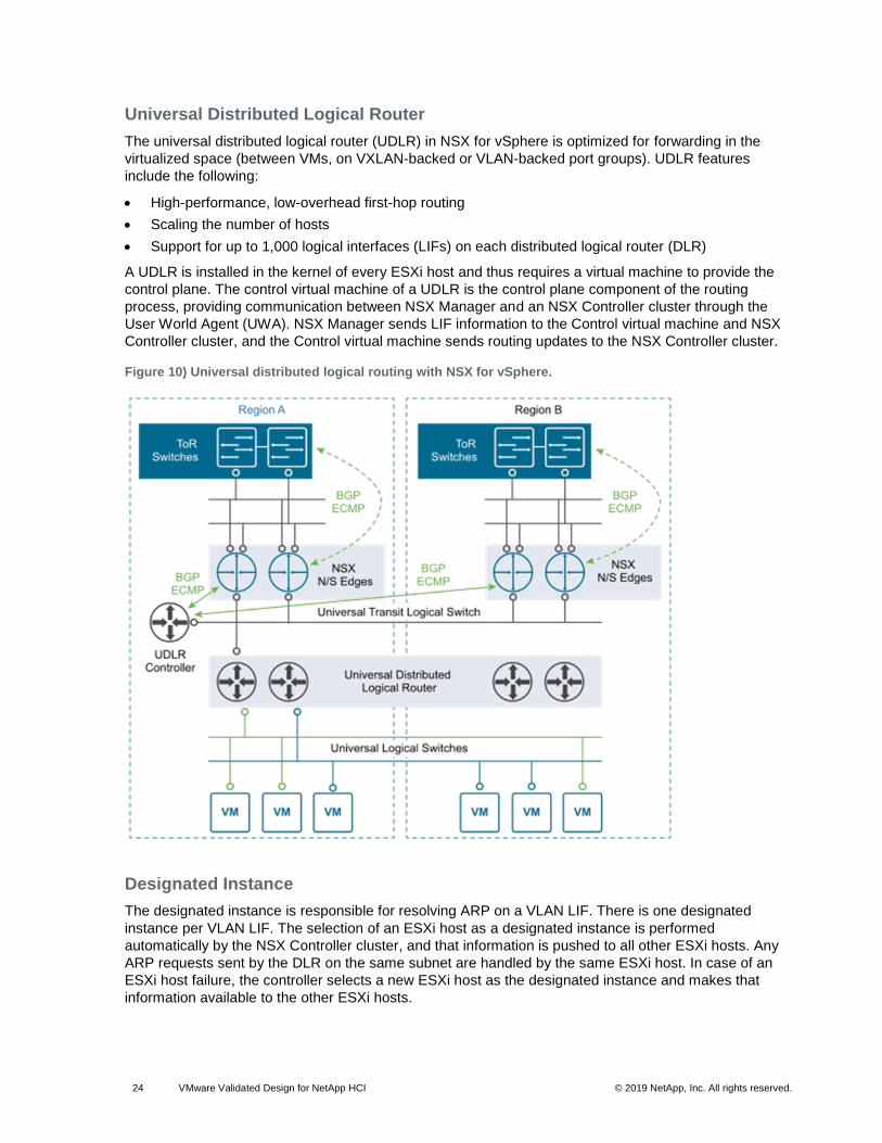
Figure 6) Quality of service trust point.
Two types of QoS configuration are supported in the physical switching infrastructure.
vSphere Distributed Switch supports both class of service and DSCP marking. Users can mark the traffic
based on the traffic type or packet classification. When the virtual machines are connected to the VXLAN-
based logical switches or networks, the QoS values from the internal packet headers are copied to the
VXLAN-encapsulated header. This enables the external physical network to prioritize the traffic based on
the tags on the external header.
Physical Network Interfaces
If the server has more than one physical network interface card (NIC) of the same speed, use two as
uplinks, with VLANs trunked to the interfaces.
vSphere Distributed Switch supports several NIC teaming options. Load-based NIC teaming supports
optimal use of available bandwidth and supports redundancy in case of a link failure. Use two 10GbE
connections for each server in combination with a pair of ToR switches. 802.1Q network trunks can
support a small number of VLANs; for example, management, storage, VXLAN, vSphere Replication, and
VMware vSphere vMotion traffic.
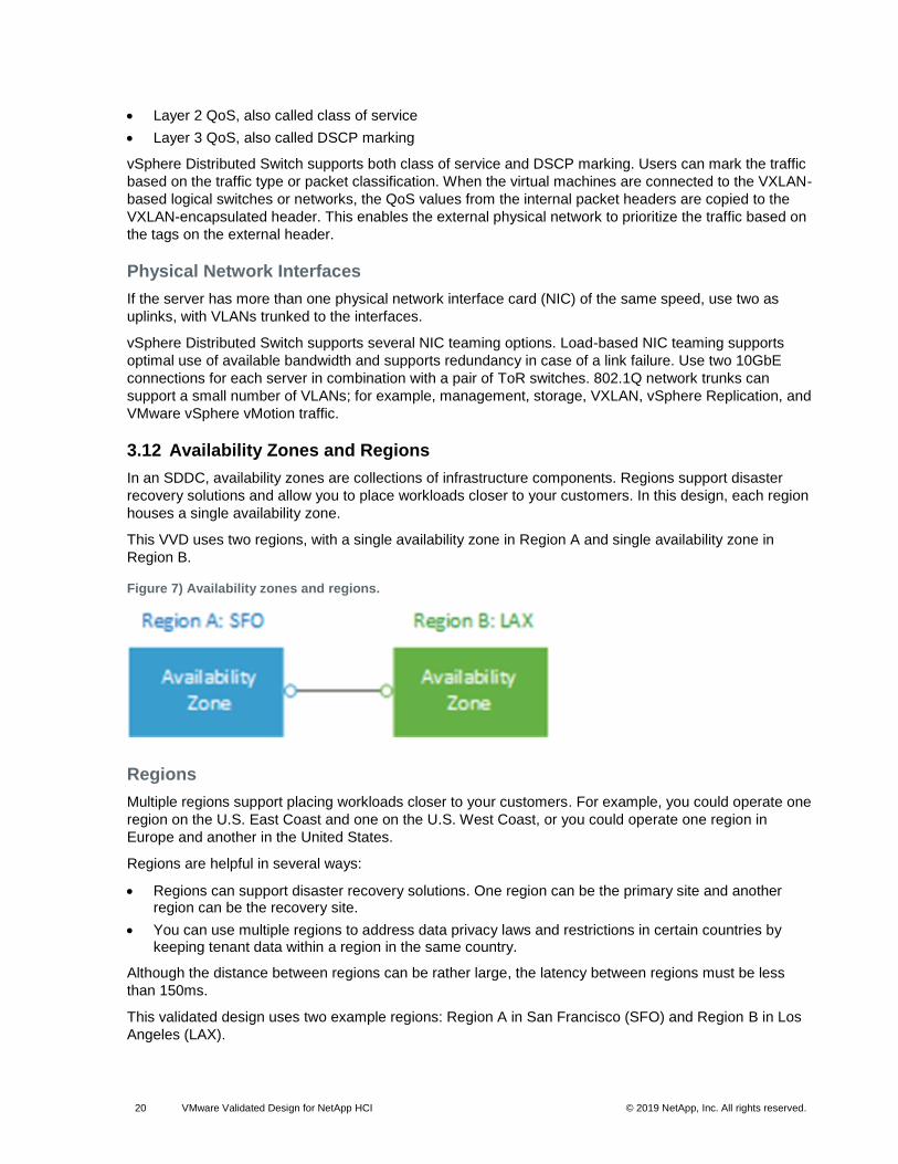
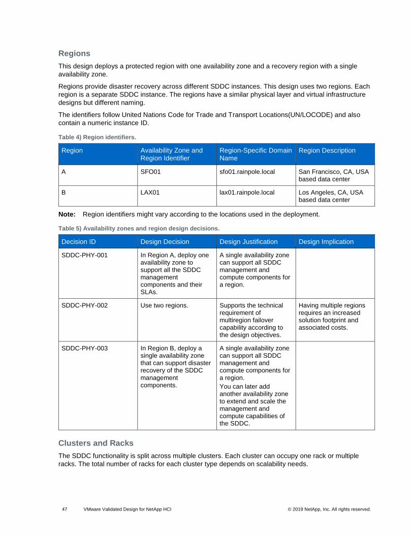
3.12 Availability Zones and Regions
In an SDDC, availability zones are collections of infrastructure components. Regions support disaster
recovery solutions and allow you to place workloads closer to your customers. In this design, each region
houses a single availability zone.
This VVD uses two regions, with a single availability zone in Region A and single availability zone in
Region B.
Figure 7) Availability zones and regions.
Regions
Multiple regions support placing workloads closer to your customers. For example, you could operate one
region on the U.S. East Coast and one on the U.S. West Coast, or you could operate one region in
Europe and another in the United States.
Regions are helpful in several ways:
• Regions can support disaster recovery solutions. One region can be the primary site and another region can be the recovery site.
• You can use multiple regions to address data privacy laws and restrictions in certain countries by keeping tenant data within a region in the same country.
Although the distance between regions can be rather large, the latency between regions must be less
than 150ms.
This validated design uses two example regions: Region A in San Francisco (SFO) and Region B in Los
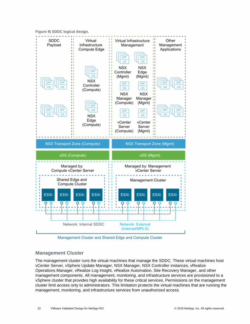
The shared edge and compute cluster runs the following components:
• NSX services that are required for north-south routing between the SDDC tenant workloads and the external network, and east-west routing in the SDDC
• Tenant workloads
As the SDDC expands, you can add more compute-only clusters to support a mix of different types of
workloads for different types of SLAs.
4.2 Network Virtualization Components
VMware NSX for vSphere, a network virtualization platform, is a key solution in the SDDC architecture.
The NSX for vSphere platform consists of several components that are relevant to the network
virtualization design.
NSX for vSphere Platform
NSX for vSphere creates a network virtualization layer. All virtual networks are created on top of this
layer, which is an abstraction between the physical and virtual networks. Several components are
required to create this network virtualization layer:
• vCenter Server
• NSX Manager
• NSX Controller
• NSX Virtual Switch
These components are separated into different planes to create communications boundaries and to
isolate workload data from system control messages.
• Data plane. Workload data is contained wholly within the data plane. NSX logical switches segregate unrelated workload data. The data is carried over designated transport networks in the physical network. The NSX vSwitch, distributed routing, and distributed firewall are also implemented in the data plane.
• Control plane. Network virtualization control messages are located in the control plane. Control plane communication should be carried on secure physical networks (VLANs) that are isolated from the transport networks used for the data plane. Control messages are used to set up networking attributes on NSX Virtual Switch instances, as well as to configure and manage disaster recovery and distributed firewall components on each ESXi host.
• Management plane. The network virtualization orchestration happens in the management plane. In this layer, CMPs such as VMware vRealize Automation can request, consume, and destroy networking resources for virtual workloads. Communication is directed from the CMP to vCenter Server to create and manage virtual machines, and to NSX Manager to consume networking resources.
4.3 Network Virtualization Services
Network virtualization services include logical switches, logical routers, logical firewalls, and other
components of NSX for vSphere.
Logical Switches
NSX for vSphere logical switches create logically abstracted segments to which tenant virtual machines
can connect. A single logical switch is mapped to a unique VXLAN segment ID and is distributed across
the ESXi hypervisors within a transport zone. This allows line-rate switching in the hypervisor without
creating constraints of VLAN sprawl or spanning tree issues.
UWA is a TCP and Secure Sockets Layer (SSL) client that enables communication between the ESXi
hosts and NSX Controller nodes. UWA also enables the retrieval of information from NSX Manager
through interaction with the message bus agent.
Edge Services Gateway
The UDLR provides virtual machine-to-virtual-machine or east-west routing, and the NSX Edge services
gateway (ESG) provides north-south connectivity by peering with upstream top-of-rack switches, thereby
enabling tenants to access public networks.
Logical Firewall
The NSX Logical Firewall provides security mechanisms for dynamic virtual data centers.
• The distributed firewall allows you to segment virtual data center entities like virtual machines. Segmentation can be based on virtual machine names and attributes, user identity, vCenter objects like data centers, and ESXi hosts. It can also be based on traditional networking attributes like IP addresses, port groups, and so on.
• The Edge Firewall component helps you meet key perimeter security requirements. These include building DMZs based on IP/VLAN constructs, tenant-to-tenant isolation in multitenant virtual data centers, Network Address Translation (NAT), partner (extranet) VPNs, and user-based SSL VPNs.
The Flow Monitoring feature displays network activity between virtual machines at the application protocol
level. You can use this information to audit network traffic, define and refine firewall policies, and identify
The architecture of the products of the operations management layer supports centralized monitoring of
data and logging data about the other solutions in the SDDC. You use this architecture to deliver core
operational procedures in the data center.
In the operations management layer, the physical infrastructure, virtual infrastructure, and tenant
workloads are monitored in real time, collecting the following information for intelligent and dynamic
operational management:
• Monitoring data, such as structured data (metrics) and unstructured data (logs)
• Topology data, such as physical and virtual compute, networking, and storage objects
Figure 11) Operations management layer of the SDDC.
5.1 Monitoring Architecture
vRealize Operations Manager tracks and analyzes the operation of multiple data sources in the SDDC by
using specialized analytic algorithms. These algorithms help vRealize Operations Manager learn and
predict the behavior of every object it monitors. Users access this information by using views, reports, and
dashboards.
Deployment
vRealize Operations Manager is available as a preconfigured virtual appliance in Open Virtual Machine
Format (OVF). By using the virtual appliance, you can easily create vRealize Operations Manager nodes
with identical predefined sizes.
You deploy the OVF file of the virtual appliance once for each node. After node deployment, you access
the product to set up cluster nodes according to their role and log in to configure the installation.
Deployment Models
You can deploy vRealize Operations Manager as a virtual appliance in one of the following
configurations:
• Standalone node
• Cluster of one master and at least one data node, and optionally a group of remote collector nodes. You can establish high availability by using an external load balancer.
For high availability and scalability, you can deploy several vRealize Operations Manager instances in a
cluster to track, analyze, and predict the operation of monitored systems. Cluster nodes can have one of
the following roles:
• Master node. Required initial node in the cluster. In large-scale environments, the master node manages all other nodes. In small-scale environments, the master node is the single standalone vRealize Operations Manager node.
• Master replica node. Optional. Enables high availability of the master node.
• Data node. Optional. Enables scale out of vRealize Operations Manager in larger environments. Data nodes have adapters installed to perform collection and analysis. Data nodes also host vRealize Operations Manager management packs.
• Remote collector node. Overcomes data collection issues across the enterprise network, such as limited network performance. You can also use remote collector nodes to offload data collection from the other types of nodes.
Remote collector nodes only gather statistics about inventory objects and forward collected data to the
data nodes. They do not store data or perform analysis. The master and master replica nodes are data
nodes that have extended capabilities.
Types of Node Groups
• Analytics cluster. Tracks, analyzes, and predicts the operation of monitored systems. Consists of a master node, data nodes, and optionally of a master replica node.
• Remote collector group. Because it consists of remote collector nodes, only collects diagnostics data without storage or analysis. A vRealize Operations Manager deployment can contain several collector groups.
• Use collector groups to achieve adapter resiliency in case the collector experiences network interruption or becomes unavailable.
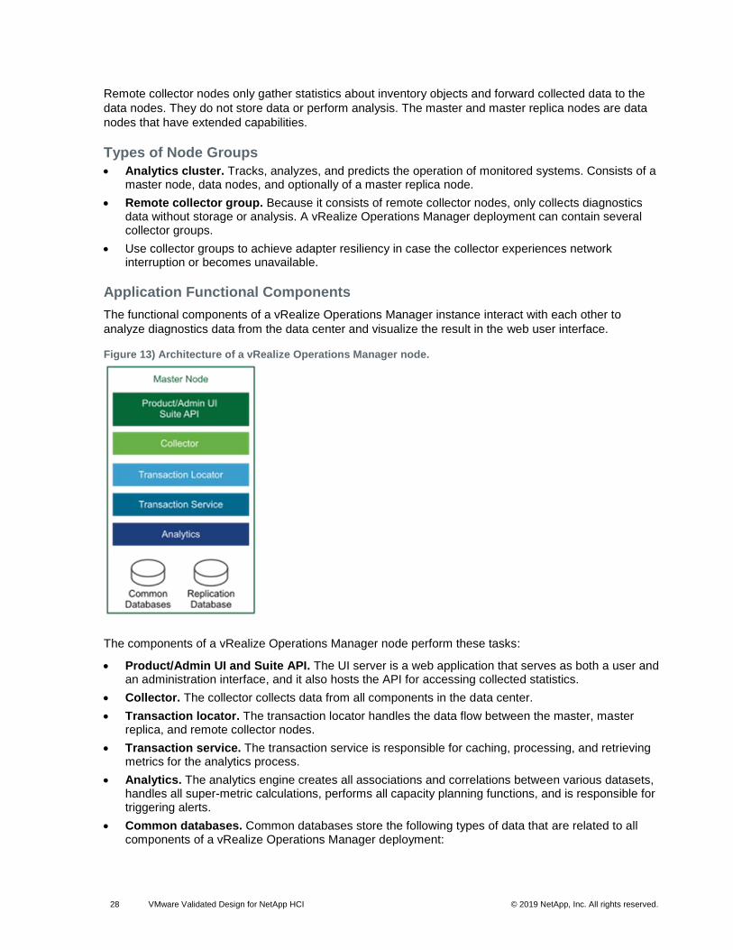
Application Functional Components
The functional components of a vRealize Operations Manager instance interact with each other to
analyze diagnostics data from the data center and visualize the result in the web user interface.
Figure 13) Architecture of a vRealize Operations Manager node.
The components of a vRealize Operations Manager node perform these tasks:
• Product/Admin UI and Suite API. The UI server is a web application that serves as both a user and an administration interface, and it also hosts the API for accessing collected statistics.
• Collector. The collector collects data from all components in the data center.
• Transaction locator. The transaction locator handles the data flow between the master, master replica, and remote collector nodes.
• Transaction service. The transaction service is responsible for caching, processing, and retrieving metrics for the analytics process.
• Analytics. The analytics engine creates all associations and correlations between various datasets, handles all super-metric calculations, performs all capacity planning functions, and is responsible for triggering alerts.
• Common databases. Common databases store the following types of data that are related to all components of a vRealize Operations Manager deployment:
− User content, metric key mappings, licensing, certificates, telemetry data, and role privileges
− Cluster administration data
− Alerts and alarms, including the root cause, and object historical properties and versions
• Replication database. The replication database stores all resources, such as metadata, relationships, collectors, adapters, and collector groups, and the relationships between them.
Authentication Sources
You can configure vRealize Operations Manager user authentication to use one or more of the following
authentication sources:
• vCenter Single Sign-On
• VMware Identity Manager
• OpenLDAP via LDAP
• Active Directory via LDAP
Management Packs
Management packs contain extensions and third-party integration software. They add dashboards, alert
definitions, policies, reports, and other content to the inventory of vRealize Operations Manager. You can
learn all about management packs, and download them, from VMware Solutions Exchange.
Backup
You back up each vRealize Operations Manager node by using traditional virtual machine backup
solutions that are compatible with VMware vSphere Storage APIs – Data Protection (VADP).
vRealize Log Insight clients connect to the ILB Virtual IP (VIP) address and use the syslog or the
Ingestion API through the vRealize Log Insight agent to send logs to vRealize Log Insight. Users and
administrators interact with the ingested logs by using the user interface or the API.
By default, vRealize Log Insight collects data from vCenter Server systems and ESXi hosts. You use
content packs to forward logs from NSX for vSphere and vRealize Automation. They contain extensions
or provide integration with other systems in the SDDC.
Types of Nodes
For functionality, high availability, and scalability, vRealize Log Insight supports the following types of
nodes, which have inherent roles:
• Master node. Required initial node in the cluster. In standalone mode, the master node is responsible for all activities, including queries and log ingestion. The master node also handles operations that are related to the lifecycle of a cluster, such as performing upgrades and adding or removing worker nodes. In a scaled-out and highly available environment, the master node still performs such lifecycle operations. However, it functions as a generic worker about queries and log ingestion activities.
The master node stores logs locally. If the master node is down, the logs stored on it become unavailable.
• Worker node. Optional. This component enables scale out in larger environments. As you add and configure more worker nodes in a vRealize Log Insight cluster for high availability (HA), queries and log ingestion activities are delegated to all available nodes. You must have at least two worker nodes to form a cluster with the master node.
The worker node stores logs locally. If any of the worker nodes is down, the logs on the worker become unavailable.
• Integrated load balancer. In cluster mode, the ILB is the centralized entry point that enables vRealize Log Insight to accept incoming ingestion traffic. As nodes are added to the vRealize Log Insight instance to form a cluster, the ILB feature simplifies the configuration for high availability. The ILB balances the incoming traffic fairly among the available vRealize Log Insight nodes.
The ILB runs on one of the cluster nodes at all times. In environments that contain several nodes, an election process determines the leader of the cluster. Periodically, the ILB performs a health check to determine whether reelection is required. If the node that hosts the ILB VIP address stops responding, the VIP address is failed over to another node in the cluster through an election process.
All queries against data are directed to the ILB. The ILB delegates queries to a query master for the duration of the query. The query master queries all nodes, both master and worker nodes, for data and then sends the aggregated data back to the client.
Use the ILB for administrative activities unless you are performing administrative activities on individual nodes. The web user interface of the ILB presents data from the master and from the worker nodes in a scaled-out cluster in a unified display (single pane of glass).
Application Functional Components
The functional components of a vRealize Log Insight instance interact with each other to perform the
following operations:
• Analyze logging data that is ingested from the components of a data center
• Visualize the results in a web browser, or support results query by using API calls
vRealize Log Insight components perform these tasks:
• Product/Admin UI and API . The UI server is a web application that serves as both user and administration interface. The server hosts the API for accessing collected statistics.
• Syslog ingestion. Responsible for ingesting syslog logging data.
• Log Insight native ingestion API (CFAPI) ingestion. Responsible for ingesting logging data over the ingestion API by using one of the following methods:
− vRealize Log Insight agent that has been deployed or preconfigured on SDDC components
− Log Insight Importer that is used for ingestion of non-real-time data
• Integration load balancing and election. Responsible for balancing incoming UI, API, and data ingestion traffic.
The ILB is a Linux Virtual Server that is built in the Linux kernel for layer 4 load balancing. Each node of vRealize Log Insight contains a service running the ILB, but only a single node functions as the leader at all times. In a single-node vRealize Log Insight instance, this is always the master node. In a scaled-out vRealize Log Insight cluster, this role can be inherited by any of the available nodes during the election process. The leader periodically performs health checks to determine whether a reelection process is required for the cluster.
• Configuration database. Stores configuration information about the vRealize Log Insight nodes and cluster. The information that is stored in the database is periodically replicated to all available vRealize Log Insight nodes.
• Log repository. Stores logging data that is ingested in vRealize Log Insight. The logging repository is local to each node and is not replicated. If a node is offline or removed, the logging data that is stored on that node becomes inaccessible. In environments where an ILB is configured, incoming logging data is evenly distributed across all available nodes.
When a query arrives from the ILB, the vRealize Log Insight node that holds the ILB leader role delegates the query to any of the available nodes in the cluster.
Authentication Models
You can configure vRealize Log Insight user authentication to use one or more of the following
• vRealize Operations Manager can provide the inventory map of any vSphere object to vRealize Log Insight. In this way, you can view log messages from vRealize Log Insight in the vRealize Operations Manager Web user interface, taking you either directly to the object itself or to the location of the object in the environment.
• Access to the vRealize Log Insight user interface is embedded in the vRealize Operations Manager user interface.
Archiving
vRealize Log Insight supports data archiving on an NFS shared storage that the vRealize Log Insight
nodes can access. However, vRealize Log Insight does not manage the NFS mount used for archiving,
and it does not clean up the archival files.
The NFS mount for archiving can run out of free space or become unavailable for a period of time greater
than the retention period of the virtual appliance. In that case, vRealize Log Insight stops ingesting new
data until the NFS mount has enough free space or becomes available, or until archiving is disabled. If
archiving is enabled, system notifications from vRealize Log Insight sends you an email when the NFS
mount is about to run out of space or is unavailable.
Backup
You back up each vRealize Log Insight cluster by using traditional virtual machine backup solutions that
are compatible with VADP.
Multiregion vRealize Log Insight Deployment
The scope of this validated design can cover multiple regions, with each region containing a single
availability zone.
In a multiregion implementation, vRealize Log Insight provides a separate logging infrastructure in each
region of the SDDC. Using vRealize Log Insight across multiple regions requires the following
configuration:
• A cluster in each region
• Event forwarding to other vRealize Log Insight deployments across regions in the SDDC
• Install and upgrade third-party software on ESXi hosts
• Upgrade virtual machine hardware and VMware Tools
Use the vSphere Update Manager Download Service (UMDS) to deploy vSphere Update Manager on a
secured, air-gapped network that is disconnected from other local networks and the internet. UMDS
provides a bridge for internet access that is required to pull down upgrade and patch binaries.
Installation Models
The installation models of vSphere Update Manager are different according to the type of vCenter Server
installation.
Table 3) Installation models of vSphere Update Manager and Update Manager Download Service.
Component Installation Model
Description
vSphere Update Manager
Embedded in the vCenter Server appliance
vSphere Update Manager is automatically registered with the container vCenter Server appliance. You access vSphere Update Manager as a plug-in from vSphere Web Client.
Use virtual appliance deployment to deploy vCenter Server and vSphere Update Manager as an all-in-one package in which sizing and maintenance for the latter is dictated by the former.
Windows installable package for installation against a Microsoft Windows vCenter Server
You must run the vSphere Update Manager installation on either vCenter Server itself or an external Microsoft Windows Server. After installation and registration with vCenter Server, you access vSphere Update Manager as a plug-in from vSphere Web Client.
Use the Windows installable deployment if you are using a vCenter Server instance for Windows.
Note: In vSphere 6.5 and later, you can only pair a vSphere Update Manager instance for Microsoft Windows with a vCenter Server instance for Windows.
Update Manager Download Service
Installable package for Linux or Microsoft Windows Server
• For a Linux deployment, install UMDS on Ubuntu 14.0.4 or Red Hat Enterprise Linux 7.0.
• For a Windows deployment, install UMDS on one of the supported host operating systems (Host OS) that are detailed in the VMware Knowledge Base article 2091273.
You cannot install UMDS on the same system as vSphere Update Manager.
Architecture
vSphere Update Manager contains functional elements that collaborate for monitoring, notifying, and
orchestrating the lifecycle management of your vSphere environment in the SDDC.
Figure 17) vSphere Update Manager and Update Manager Download Service architecture.
Types of Nodes
For functionality and scalability, vSphere Update Manager and Update Manager Download Service
perform the following roles:
• vSphere Update Manager. Required node for integrated, automated lifecycle management of vSphere components. In environments ranging from a single instance to multiple vCenter Server instances, vSphere Update Manager is paired in a 1:1 relationship.
• Update Manager Download Service. In a secure environment in which there is an air gap between vCenter Server and vSphere Update Manager and internet access, UMDS provides the bridge for vSphere Update Manager to receive its patch and update binaries. In addition, you can use UMDS to aggregate downloaded binary data, such as patch metadata, patch binaries, and notifications. This binary data can then be shared across multiple instances of vSphere Update Manager to manage the lifecycle of multiple vSphere environments.
Backup
You can back up vSphere Update Manager in two ways – either as an embedded service on the vCenter
Server appliance or deployed separately on a Microsoft Windows Server virtual machine. UMDS is
backed up by using traditional virtual machine backup solutions. Such solutions are based on software
that is compatible with VADP.
Multiregion Deployment of vSphere Update Manager and UMDS
Because of its multiregion scope, the VVD for SDDC uses vSphere Update Manager and UMDS in each
region to provide automated lifecycle management of the vSphere components. If you have a vSphere
Update Manager service instance with each vCenter Server deployed, you can deploy one UMDS
instance per region. In this way, you have a central repository of aggregated patch binaries that are
securely downloaded.
Failing over UMDS by using vSphere Replication and Site Recovery Manager is not necessary because
vRealize Automation provides self-service provisioning, IT services delivery, and lifecycle management of
cloud services across a wide range of multivendor, virtual, physical, and cloud platforms though a flexible
and robust distributed architecture. The two main functional elements of the architecture are the vRealize
Automation server and the IaaS components.
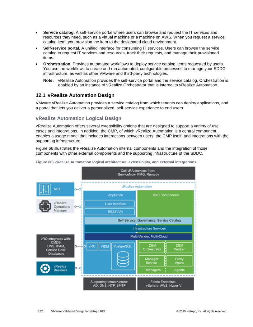
Figure 20) vRealize Automation architecture.
• vRealize Automation server appliance. The vRealize Automation server is deployed as a preconfigured Linux virtual appliance. The vRealize Automation server appliance is delivered as an open virtualization file (OVF) that you deploy on an existing virtualized infrastructure such as vSphere. It performs the following functions:
− vRealize Automation product portal, where users log in to access self-service provisioning and management of cloud services
− Single sign-on (SSO) for user authorization and authentication
− Management interface for vRealize Automation appliance settings
• Embedded vRealize Orchestrator. The vRealize Automation appliance contains a preconfigured instance of vRealize Orchestrator. vRealize Automation uses vRealize Orchestrator workflows and actions to extend its capabilities.
• PostgreSQL Database. vRealize Server uses a preconfigured PostgreSQL database that is included in the vRealize Automation appliance. This database is also used by the instance of vRealize Orchestrator in the vRealize Automation appliance.
• IaaS. vRealize Automation IaaS consists of one or more Microsoft Windows servers that work together to model and provision systems in private, public, or hybrid cloud infrastructures.
• Model Manager. vRealize Automation uses models to facilitate integration with external systems and databases. The models implement business logic used by the Distributed Execution Manager (DEM).
The Model Manager provides services and utilities for persisting, versioning, securing, and distributing model elements. Model Manager is hosted on one of the IaaS web servers and communicates with DEMs, the SQL Server database, and the product interface web site.
• IaaS web server. The IaaS web server provides infrastructure administration and service authoring to the vRealize Automation product interface. The web server component communicates with the manager service, which provides updates from the DEM, SQL Server database, and agents.
• Manager service. Windows service that coordinates communication between IaaS DEMs, the SQL Server database, agents, and SMTP. The manager service communicates with the web server through the Model Manager and must be run under a domain account with administrator privileges on all IaaS Windows servers.
• Distributed Execution Manager Orchestrator. A DEM executes the business logic of custom models, interacting with the database and external databases and systems as required. A DEM orchestrator is responsible for monitoring DEM Worker instances, preprocessing workflows for execution, and scheduling workflows.
• Distributed Execution Manager Worker. The vRealize Automation IaaS DEM Worker executes provisioning and deprovisioning tasks initiated by the vRealize Automation portal. DEM Workers also communicate with specific infrastructure endpoints.
• Proxy agents. vRealize Automation IaaS uses agents to integrate with external systems and to manage information among vRealize Automation components. For example, vSphere proxy agent sends commands to and collects data from a vSphere ESX Server for the VMs provisioned by vRealize Automation.
• VMware Identity Manager. VMware Identity Manager is the primary identity provider for vRealize Automation, and manages user authentication, roles, permissions, and overall access into vRealize Automation by means of federated identity brokering. The following authentication methods are supported in vRealize Automation using VMware Identity Manager:
− Username and password providing single-factor password authentication with basic Active Directory configuration for local users
− Kerberos
− Smart card/certificate
− RSA SecurID
− RADIUS
− RSA Adaptive Authentication
− SAML Authentication
VMware Validated Design Deployment Model
The scope of this VVD includes vRealize Automation appliance large-scale distributed deployment
designed for a full-fledged, highly available Cloud Management Portal solution that includes:
• Two vRealize Automation server appliances behind a load balancer
• Two vRealize Automation IaaS web servers behind a load balancer
• Two vRealize Automation Manager Service nodes (including DEM Orchestrator) behind a load balancer
• Two DEM Worker nodes
• Two IaaS proxy agent nodes
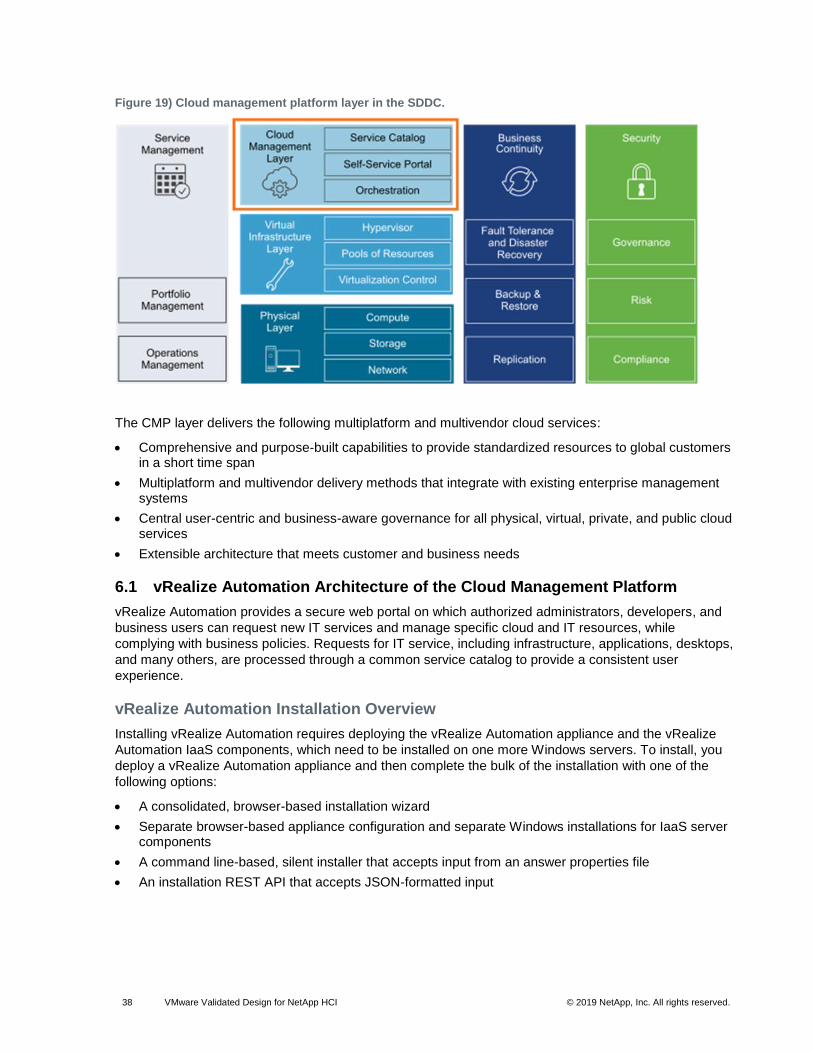
6.2 vRealize Business for Cloud Architecture
VMware vRealize Business for Cloud automates cloud costing, consumption analysis, and comparison,
delivering the insight you need to efficiently deploy and manage cloud environments.
vRealize Business for Cloud tracks and manages the costs of private and public cloud resources from a
single dashboard. It offers a comprehensive way to view, plan, and manage your cloud costs. vRealize
Business for Cloud is tightly integrated with vRealize Automation. The architecture illustrates the main
components of vRealize Business for Cloud: the server, the FactsRepo inventory service, the data
transformation service, data collection services, and the reference database.
Figure 21) vRealize Business for Cloud.
• Data collection services. A set of services for each private and public cloud endpoint, such as vCenter Server, vCloud Director, Amazon Web Services (AWS), and vCloud Air. The data collection services retrieve both inventory information (servers, virtual machines, clusters, storage devices, and associations between them) and usage statistics (CPU and memory). The data collection services use the collected data for cost calculations.
Note: You can deploy vRealize Business for Cloud in such a way that only its data collection services are enabled. This version of the vRealize Business appliance is known as a remote data collector. Remote data collectors reduce the data collection workload of vRealize Business for Cloud Servers and enable remote data collection from geographically distributed endpoints.
• FactsRepo inventory service. An inventory service built on MongoDB to store the collected data that vRealize Business for Cloud uses for cost computation.
• Data transformation service. Converts source-specific data from the data collection services into data structures for consumption by the FactsRepo inventory service. The data transformation service serves as is a single point of data aggregation from all data collectors.
• vRealize Business for Cloud Server. A web application that runs on Pivotal tc Server. vRealize Business for Cloud has multiple data collection services that run periodically, collecting inventory information and statistics, which are in turn stored in a PostgreSQL database as the persistent data store. Data collected from the data collection services is used for cost calculations.
• Reference database. Responsible for providing default, out-of-the-box costs for each of the supported cost drivers. The reference database is updated automatically or manually, and you can download the latest dataset and import it into vRealize Business for Cloud. The new values affect cost calculations. The reference data used depends on the currency you select at the time of installation.
Note: You cannot change the currency configuration after you deploy vRealize Business for Cloud.
• Communication between the server and the reference database. The reference database is a compressed and encrypted file that you can download and install manually or update automatically. For more information, see Update the Reference Database for vRealize Business for Cloud.
• Other sources of information. Other sources include vRealize Automation, vCloud Director, vRealize Operations Manager, AWS, Microsoft Azure and vCloud Air, and EMC Storage Resource Manager (SRM). These information sources are optional and are used only if installed and configured.
• vRealize Business for Cloud operational model. vRealize Business for Cloud continuously collects data from external sources and periodically updates the FactsRepo inventory service. You can view the collected data by using the vRealize Business for Cloud dashboard, or you can generate a report. The data synchronization and updates occur at regular intervals. However, you can manually trigger the data collection process when inventory changes occur. For example, you can trigger in response to the initialization of the system, or the addition of a private, public, or hybrid cloud account.
• vRealize Business for Cloud deployment model. VVD uses three virtual machines: a single vRealize Business for Cloud Server appliance, a single vRealize Business for Cloud remote data collector for Region A, and a single vRealize Business for Cloud remote data collector for Region B.
7 Business Continuity Architecture
The architecture of the business continuity layer includes management components that support backup,
restore, and disaster recovery procedures. Within the business continuity layer, management
components are implemented to handle the following business continuity requirements:
Figure 23) Dual-region data protection architecture.
Multiregion Data Protection Deployment
Because of its multiregion scope, the VVD for SDDC calls for the deployment of a VADP-compatible
backup solution in the management cluster for each region. Backup jobs are configured to provide
recovery of a number of SDDC management components. A VADP-compatible backup solution stores
the backups of the management virtual appliances on secondary storage according to a defined
schedule.
7.2 Disaster Recovery Architecture
You use Site Recovery Manager in conjunction with vSphere Replication and their constructs to
implement cross-region disaster recovery for the workloads of the management products in the SDDC.
Architecture
Disaster recovery that is based on Site Recovery Manager has the following main elements:
• Dual-region configuration. All protected virtual machines are initially located in Region A, the protected region, and are recovered in Region B, the recovery region. In a typical Site Recovery Manager installation, the protected region provides business-critical data center services. The recovery region is an alternative infrastructure to which Site Recovery Manager can relocate these services.
• Replication of virtual machine data. When you use array-based replication, one or more storage arrays at the protected region replicate data to peer arrays at the recovery region. To use array-based replication with Site Recovery Manager, you must first configure replication on the storage array and install a storage-specific adapter before you can configure Site Recovery Manager to use it.
• vSphere Replication. You configure vSphere Replication on virtual machines independently of Site Recovery Manager. Replication does not occur at the storage array level. The replication source and target storage can be any storage device.
Note: You can configure vSphere Replication to use the multiple-point-in-time snapshot feature. This configuration offers greater flexibility for data recovery of protected virtual machines on the recovery region.
• Protection groups. A protection group is a group of virtual machines that fail over together at the recovery region during test and recovery. Each protection group protects one datastore group, and each datastore group can contain multiple datastores. However, you cannot create protection groups that combine virtual machines protected by array-based replication and vSphere Replication.
• Recovery plans. A recovery plan specifies how Site Recovery Manager recovers the virtual machines in the protection groups. You can include a combination of array-based replication protection groups and vSphere Replication protection groups in the same recovery plan.
Figure 24) Disaster recovery architecture.
Multiregion Site Recovery Manager Deployment
This VVD for SDDC pairs two Site Recovery Manager servers deployed on the management cluster. This
design implements the following disaster recovery configuration:
• The following management applications are protected in the event of a disaster:
− vRealize Automation and vRealize Business Server
− The analytics cluster of vRealize Operations Manager
• The virtual infrastructure components that are not covered by disaster recovery protection, such as vRealize Log Insight, are available as separate instances in each region.
8 Detailed Design
This detailed SDDC design covers both physical and virtual infrastructure design. It includes numbered
design decisions and the justification and implications of each decision.
• Physical infrastructure design. Focuses on the three main pillars of any data center: compute, storage, and network. This section contains information about availability zones and regions. It also
provides details on the rack and cluster configuration, and on physical ESXi hosts and the associated storage and network configurations.
• Virtual infrastructure design. Describes the core virtualization software configuration. This section has information about the ESXi hypervisor, vCenter Server, the virtual network design including VMware NSX, and software-defined storage for NetApp HCI. This section also includes details on business continuity (backup and restore) and disaster recovery.
• CMP design. Contains information about the consumption and orchestration layer of the SDDC stack, which uses vRealize Automation and vRealize Orchestrator. IT organizations can use the fully distributed and scalable architecture to streamline their provisioning and decommissioning operations.
• Operations infrastructure design. Explains how to architect, install, and configure vRealize Operations Manager and vRealize Log Insight. You learn how to make sure that service management within the SDDC is comprehensive. This section ties directly into the Operational Guidance section.
9 Physical Infrastructure Design
The physical infrastructure design includes decisions for availability zones and regions and the cluster
layout in data center racks. Design decisions related to server, networking, and storage hardware are part
of the physical infrastructure design.
Figure 25) Physical infrastructure design.
9.1 Physical Design Fundamentals
Physical design fundamentals include decisions about availability zones, regions, workload domains, clusters, and racks. The ESXi host physical design is also a part of design fundamentals.
• Physical Networking Design. VVD for SDDC can use most enterprise-grade physical network architectures.
• Physical Storage Design. This VVD uses different types of storage. Section 10.8, Shared Storage Design, contains background information and explains where the SDDC uses each type of storage.
Decision ID Design Decision Design Justification Design Implication
SDDC-PHY-004 In each region, place the management cluster and the shared edge and compute cluster in the same rack.
The number of required compute resources for the management cluster (four ESXi servers) and shared edge and compute cluster (four ESXi servers) is low and does not justify a dedicated rack for each cluster.
On-ramp and off-ramp connectivity to physical networks (for example, north-south layer 3 routing on NSX Edge virtual appliances) can be supplied to both the management and compute clusters through this management and edge rack.
Edge resources require external connectivity to physical network devices. Placing edge resources for management and compute in the same rack minimizes VLAN spread.
The data centers must include sufficient power and cooling to operate the server equipment. This depends on the selected vendor and products.
If the equipment in this entire rack fails, a second region is needed to mitigate the downtime associated with such an event.
SDDC-PHY-005 External storage occupies one or more racks.
To simplify the scale out of the SDDC infrastructure, the storage-to-racks relationship has been standardized.
It is possible that the storage system arrives from the manufacturer in a dedicated rack or set of racks. A storage system of this type is accommodated in the design.
Data centers must include sufficient power and cooling to operate the storage equipment. This depends on the selected vendor and products.
Decision ID Design Decision Design Justification Design Implication
SDDC-PHY-006 Use two separate power feeds for each rack.
Redundant power feeds increase availability by making sure that failure of a power feed does not bring down all equipment in a rack.
Combined with redundant network connections into a rack and within a rack, redundant power feeds prevent failure of equipment in an entire rack.
All equipment used must support two separate power feeds. The equipment must keep running if one power feed fails.
If the equipment of an entire rack fails, the cause, such as flooding or an earthquake, also affects neighboring racks. Use a second region to reduce the downtime associated with such an event.
SDDC-PHY-007 Mount the compute resources (minimum of four ESXi hosts) for the management cluster together in a rack.
Mounting the compute resources for the management cluster together can ease physical data center design, deployment, and troubleshooting.
None
SDDC-PHY-008 Mount the compute resources for the shared edge and compute cluster (minimum of four ESXi hosts) together in a rack.
Mounting the compute resources for the shared edge and compute cluster together can ease physical data center design, deployment, and troubleshooting.
None
ESXi Host Physical Design Specifications
The physical design specifications of the ESXi host list the characteristics of the ESXi hosts that were
used during deployment and testing of this VVD.
Physical Design Specification Fundamentals
The configuration and assembly process for each system is standardized, with all components installed in
the same manner on each ESXi host. Standardizing the entire physical configuration of the ESXi hosts is
crucial to providing an easily manageable and supportable infrastructure, because standardization
eliminates variability. Deploy ESXi hosts with an identical configuration, including identical storage, and
networking configurations, across all cluster members. For example, consistent PCI card slot placement,
especially for network controllers, is essential for accurate alignment of physical to virtual I/O resources.
Using identical configurations creates an even balance of virtual machine storage components across
storage and compute resources.
All of these recommendations are met in this design through the use of NetApp HCI compute nodes.
Select all nodes on a per-cluster basis from Table 7.
Decision ID Design Decision Design Justification Design Implication
SDDC-PHY-009 Use NetApp HCI E-Series compute nodes
Standardized compute node hardware configurations creates a seamless deployment, verifies VMware HCL compatibility, and eases troubleshooting.
Hardware choices might be limited.
SDDC-PHY-010 You must verify that all nodes have uniform configurations across a given cluster.
A balanced cluster delivers more predictable performance even during hardware failures. In addition, performance impact during maintenance mode evacuations and similar operations is minimal if the cluster is balanced.
None
ESXi Host Memory
The amount of memory required for compute clusters varies according to the workloads running in the
cluster. When sizing memory for compute cluster hosts, it is important to remember the admission control
setting (n+1), which reserves one host resource for failover or maintenance.
Table 9) Host memory design decision.
Decision ID Design Decision Design Justification Design Implication
SDDC-PHY-011 Use NetApp HCI H300E (small) compute nodes for the management cluster.
The management and edge VMs in this cluster require a total of 424GB RAM. 4x H300E compute nodes provide more than enough RAM and CPU resources to accommodate these needs, up to the N+2 level (for example, two hosts can be in maintenance mode).
Host boot devices are provided by two M.2 SATA solid-state drives (SSDs) that are automatically
configured by the NetApp Deployment Engine.
9.2 Physical Networking Design
VVD for SDDC can use most enterprise-grade physical network architectures.
Switch Types and Network Connectivity
Setting up the physical environment requires careful consideration. Follow best practices for physical
switches, switch connectivity, VLANs, subnets, and access port settings.
Top-of-Rack Physical Switches
When configuring top-of-rack (ToR) switches, consider the following best practices.
• Configure redundant physical switches to enhance availability.
• Configure switch ports that connect to ESXi hosts manually as trunk ports. Virtual switches are passive devices and do not support trunking protocols, such as the Dynamic Trunking Protocol.
• Modify the Spanning Tree Protocol on any port that is connected to an ESXi NIC to reduce the time it takes to transition ports over to the forwarding state, for example by using the Trunk PortFast feature found in a physical Cisco switch.
• Provide DHCP or DHCP Helper capabilities on all VLANs that are used by management and VXLAN VMkernel ports. This setup simplifies the configuration by using DHCP to assign IP address based on the IP subnet in use.
• Configure jumbo frames on all switch ports, interswitch links (ISLs), and switched virtual interfaces (SVIs).
Top-of-Rack Connectivity and Network Settings
Each ESXi host is connected redundantly to the SDDC network fabric ToR switches by means of two
10GbE ports. Configure the ToR switches to provide all necessary VLANs through an 802.1Q trunk.
These redundant connections use features in vSphere Distributed Switch and NSX for vSphere so that no
physical interface is overrun and redundant paths are used as long as they are available.
This validated design does not use hardware-based link aggregation for the compute nodes. However, it
does use it for the 10/25GbE ports on the storage nodes. It is important that the switches chosen offer
some form of multichassis link aggregation (MLAG) that supports LACP.
Each ESXi host uses VLANs and corresponding subnets.
Follow these guidelines:
• Use only /24 subnets to reduce confusion and mistakes when dealing with IPv4 subnetting.
• Use the IP address .253 as the floating interface with .251 and .252 for the Virtual Router Redundancy Protocol (VRPP) or the Hot Standby Routing Protocol (HSRP).
• Use the RFC1918 IPv4 address space for these subnets and allocate one octet by region and another octet by function. For example, the mapping 172.regionid.function.0/24 results in the
following sample subnets.
Note: The following VLANs and IP ranges are samples. Your actual implementation depends on your environment.
Table 10) Sample values for VLANs and IP ranges.
Cluster Function Sample VLAN Sample IP Range
Management Management 1611 (native, stretched)
172.16.11.0/24
vMotion 1612 172.16.12.0/24
VXLAN 1614 172.16.14.0/24
iSCSI 1613 172.16.13.0/24
Shared Edge and Compute
Management 1631 (native) 172.16.31.0/24
vMotion 1632 172.16.32.0/24
VXLAN 1634 172.16.34.0/24
iSCSI 1633 172.16.33.0/24
Access Port Network Settings
Configure additional network settings on the access ports that connect the ToR switches to the
corresponding servers.
• Spanning Tree Protocol (STP). Although this design does not use the STP, switches usually come with STP configured by default. Designate the access ports as trunk PortFast.
• Trunking. Configure the VLANs as members of an 802.1Q trunk with the management VLAN acting as the native VLAN.
• MTU (Maximum Transmission Unit). Set MTU for all VLANS and SVIs (management, vMotion, VXLAN, and storage) to jumbo frames for consistency.
• DHCP Helper. Configure the VIF of the management and VXLAN subnet as a DHCP proxy.
• Multicast. Configure Internet Group Management Protocol (IGMP) snooping on the ToR switches and include an IGMP querier on each VXLAN VLAN.
Region Interconnectivity
The SDDC management networks, the VXLAN kernel ports, and the edge and compute VXLAN kernel
ports of the two regions must be connected. These connections can be over a VPN tunnel, point-to-point
circuits, Multiprotocol Label Switching (MPLS), and so on. End users must be able to reach the public-
facing network segments (public management and tenant networks) of both regions.
The region interconnectivity design must support jumbo frames and provide latency of less than 150ms.
For full details on the requirements for region interconnectivity, see the Cross-vCenter NSX Installation
Guide.
The design of a region connection solution is out of scope for this VVD.
Physical Network Design Decisions
The physical network design decisions determine the physical layout and use of VLANs. They also
include decisions on jumbo frames and on other network-related requirements such as DNS and NTP.
Physical Network Design Decisions
• Routing protocols. Base the selection of the external routing protocol on your current implementation or on the expertise of the IT staff. Take performance requirements into consideration. Possible options are Open Shortest Path First (OSPF), the BGP, and Intermediate System to Intermediate System (IS-IS). Although each routing protocol has a complex set of advantages and disadvantages, this validated design uses BGP as its routing protocol.
• DHCP proxy. Set the DHCP proxy to point to a DHCP server by way of its IPv4 address. See the VVD Planning and Preparation document for details on the DHCP server.
Table 11) Physical network design decisions.
Decision ID Design Decision Design Justification Design Implication
SDDC-PHY-NET-001 The physical network architecture must support the following requirements:
• One 10GbE port on each ToR switch for ESXi host uplinks
• No ether-channel (LAG/vPC) configuration for ESXi host uplinks
• Layer 3 device that supports BGP and IGMP
Guarantees availability during a switch failure.
This design uses vSphere host profiles that are not compatible with link-aggregation technologies.
BGP is used as the dynamic routing protocol in this design.
NSX Hybrid mode replication requires IGMP.
Hardware choices might be limited.
Requires dynamic routing protocol configuration in the physical networking stack.
SDDC-PHY-NET-002 Use a physical network that is configured for BGP routing adjacency.
This design uses BGP as its routing protocol. Supports flexibility in network design for routing multisite and multitenancy workloads.
Requires BGP configuration in the physical networking stack.
SDDC-PHY-NET-003 Use two ToR switches for each rack.
This design uses two 10GbE links to each server to provide redundancy and reduce the overall design complexity.
Requires two ToR switches per rack, which can increase costs.
Decision ID Design Decision Design Justification Design Implication
SDDC-PHY-NET-004 Use VLANs to segment physical network functions.
• Supports physical network connectivity without requiring many NICs.
• Isolates the different network functions of the SDDC so that you can have differentiated services and prioritized traffic as needed.
Requires uniform configuration and presentation on all the trunks made available to the ESXi hosts.
Additional Design Decisions
Additional design decisions deal with static IP addresses, DNS records, and the required NTP time
source.
Table 12) Additional network design decisions.
Decision ID Design Decision Design Justification Design Implication
SDDC-PHY-NET-005 Assign static IP addresses to all management components in the SDDC infrastructure except for NSX VXLAN Tunnel Endpoints (VTEPs), which DHCP assigns.
Avoids connection outages due to DHCP availability or misconfiguration.
Requires accurate IP address management.
SDDC-PHY-NET-006 Create DNS records for all management nodes to enable forward, reverse, short, and fully qualified domain name (FQDN) resolution.
Ensures consistent resolution of management nodes by using both IP address (reverse lookup) and name resolution.
None
SDDC-PHY-NET-007 Use an NTP time source for all management nodes.
It is crucial to maintain accurate and synchronized time between management nodes.
None
Jumbo Frames Design Decisions
IP storage throughput can benefit from the configuration of jumbo frames. Increasing the per-frame
payload from 1500 bytes to the jumbo frame setting improves the efficiency of data transfer. Jumbo
frames must be configured end to end, which is feasible in a LAN environment. When you enable jumbo
frames on an ESXi host, you have to select an MTU that matches the MTU of the physical switch ports.
The workload determines whether it makes sense to configure jumbo frames on a virtual machine. If the
workload consistently transfers large amounts of network data, configure jumbo frames, if possible. In that
case, confirm that both the virtual machine operating system and the virtual machine NICs support jumbo
frames.
Using jumbo frames also improves the performance of vSphere vMotion.
Note: VXLAN requires an MTU value of at least 1600 bytes on the switches and routers that carry the transport zone traffic.
Table 13) Jumbo frames design decision.
Decision ID Design Decision Design Justification Design Implication
SDDC-PHY-NET-008 Configure the MTU size to at least 9000 bytes (jumbo frames) on the physical switch ports and distributed switch port groups that support the following traffic types.
• NFS
• iSCSI
• vMotion
• VXLAN
• vSphere Replication
Improves traffic throughput.
To support VXLAN, increase the MTU setting to a minimum of 1600 bytes. Setting this port group to 9000 bytes has no effect on VXLAN but ensures consistency across port groups that are adjusted from the default MTU size.
When adjusting the MTU packet size, you must also configure the entire network path (VMkernel port, distributed switch, physical switches, and routers) to support the same MTU packet size.
9.3 Physical Storage Design
This VVD uses different types of storage. Section 10.8, Shared Storage Design, explains where the
SDDC uses each type and also provides background information. The focus of this section is physical
storage design. All functional testing and validation of the designs was performed using NetApp HCI for
guest VMs and datastores and NetApp ONTAP Select for file services.
NetApp Element Software
NetApp Element® software is designed for data centers in which rapid, modular growth or contraction is
required for diverse workloads. Element is the storage infrastructure of choice for service providers, due
to its flexible handling of permanent and transient workloads with various throughput and capacity
requirements.
Element provides modular, scalable performance, with each storage node delivering guaranteed capacity
and throughput to the environment. Each Element storage node added to a NetApp HCI environment
provides a set amount of IOPS and capacity, allowing predictable, plannable growth.
Because each node provides a set throughput (IOPS) to the storage environment, QoS for each workload
can be guaranteed. Minimum SLAs are assured with Element because the total throughput of the cluster
is a known, quantifiable amount.
Element offers inline data deduplication and compression, enabling efficiency. Deduplication is performed
at a cluster-wide scale, improving overall efficiency as used capacity increases.
The design of Element is based on ease of use. It has fewer “nerd knobs” because it offers the most
efficient use with the fewest trade-offs. Element uses iSCSI configuration to eliminate the need for the
elaborate tables of initiators and targets found in FC configurations. The use of iSCSI also provides
automatic scaling capabilities and the inherent ability to take advantage of new Ethernet capabilities.
Finally, Element was designed for automation. All storage features are available through APIs, which are
the only methods used by the UI to control the system. VMware private cloud utilities can consume these
APIs to make self-service resources and fully integrated monitoring and debugging available to VMware
management tools.
For more information, see the Element product page.
Figure 28) Compute and storage nodes installed in H-Series chassis.
Note: The number of storage nodes in a NetApp HCI environment is independent of the number of compute nodes. Usually, deployments have a different number of storage nodes than compute nodes because storage requirements in an environment can vary greatly.
Chassis-based storage nodes require access to the hot-swappable 2.5-inch SSDs in the front of the
NetApp HCI H-series chassis. Because of this, you must place a storage node in a chassis slot that
corresponds to its six available drives. You can load compute nodes into any slot in the NetApp HCI
chassis that does not have drives populated for that slot; compute nodes do not use external SSD
storage.
The SSD drives for the storage nodes are arranged in groups of six across the front of the chassis. Each
storage node has a fixed set of six SSD drives connected to it. If you move a storage node from one
chassis slot to another, you must also move the corresponding drives in the front of the chassis. You
must populate all six drives for each storage node.
Figure 29 shows the front of a 4-node storage chassis:
When you design the physical network, port bonding should be configured as follows:
• In this design, both 10/25GbE switch ports facing each NetApp HCI storage node should be bonded together in an MLAG (cross-switch link aggregation) that supports LACP.
• The 10/25GbE switch ports facing each NetApp HCI compute node should not be bonded together in any way. NIC teaming and load balancing for these ports is handled at the vSphere layer in this design.
Figure 33) Switch port bonding for compute and storage nodes.
Note: Only the two 10/25GbE ports on each storage node must be bonded with MLAG/LACP. The two 1Gb management ports do not need to be bonded.
Refer to your switch vendor’s documentation for specific information about how to design and configure
MLAG port bonding across switches. The details vary greatly because each switch vendor implements
MLAG in its own proprietary way.
Second, the network used for iSCSI in this design must not be the native VLAN on either the compute or
storage nodes. It must be the same VLAN on both compute and storage nodes, and it must be tagged on
• VMware host client. HTML5-based client that has a similar interface to vSphere Web Client but is only used to manage single ESXi hosts. You use the VMware host client to conduct emergency management when vCenter Server is temporarily unavailable.
You can enable or disable each method. By default, ESXi Shell and SSH are disabled to secure the ESXi
host. The DCUI is disabled only if Strict Lockdown mode is enabled.
ESXi User Access
By default, root is the only user who can log in to an ESXi host directly. However, you can add ESXi hosts
to an Active Directory domain. After the ESXi host has been added to an Active Directory domain, access
can be granted through Active Directory groups. Auditing logins into the ESXi host also becomes easier.
Table 17) ESXi user access design decisions.
Decision ID Design Decision Design Justification Design Implication
SDDC-VI-ESXi-002 Add each ESXi host to the Active Directory domain for the region in which the ESXi host resides.
Using Active Directory membership allows greater flexibility in granting access to ESXi hosts.
Ensuring that users log in with a unique user account allows greater visibility for auditing.
Adding ESXi hosts to the domain can add some administrative overhead.
SDDC-VI-ESXi-003 Change the default ESX Admins group to the SDDC-Admins Active Directory group. Add ESXi administrators to the SDDC-Admins group following standard access procedures.
Having an SDDC-Admins group is more secure because it removes a known administrative access point. In addition, different groups allow the separation of management tasks.
Additional changes to the ESXi hosts advanced settings are required.
Virtual Machine Swap Configuration
When a virtual machine is powered on, the system creates a VMkernel swap file to serve as a backing
store for the virtual machine's RAM contents. The default swap file is stored in the same location as the
virtual machine's configuration file. This simplifies the configuration; however, it can cause excessive
unneeded replication traffic.
You can reduce the amount of traffic that is replicated by changing the swap file location to a user-
configured location on the ESXi host. However, it can take longer to perform VMware vSphere vMotion
operations when the swap file has to be recreated.
ESXi Design Decisions about NTP and Lockdown Mode Configuration
Table 18) Other ESXi host design decisions.
Decision ID Design Decision Design Justification Design Implication
SDDC-VI-ESXi-004 Configure all ESXi hosts to synchronize time with the central NTP servers.
Required because the deployment of a vCenter Server appliance on an ESXi host might fail if the host is not using NTP.
All firewalls located between the ESXi host and the NTP servers must allow NTP traffic on the required network ports.
Decision ID Design Decision Design Justification Design Implication
SDDC-VI-ESXi-005 Enable Lockdown mode on all ESXi hosts.
Increases the security of ESXi hosts by requiring administrative operations to be performed only from vCenter Server.
Lockdown mode settings are not part of host profiles and must be manually enabled on all hosts.
10.5 vCenter Server Design
The vCenter Server design includes both the design for the vCenter Server instance and the VMware
Platform Services Controller instance.
A Platform Services Controller groups a set of infrastructure services including vCenter Single Sign-On,
License Service, Lookup Service, and VMware Certificate Authority (VMCA). You can deploy the Platform
Services Controller and the associated vCenter Server system on the same virtual machine (vCenter
Server with an embedded Platform Services Controller). You can also deploy it on a different virtual
machines (vCenter Server with an external Platform Services Controller).
• vCenter Server Deployment. The design decisions for vCenter Server deployment include the number of vCenter Server and Platform Services Controller instances, the type of installation, and the topology.
• vCenter Server Networking. As specified in the physical networking design, all vCenter Server systems must use static IP addresses and host names. The IP addresses must have valid internal DNS registration, including reverse name resolution.
• vCenter Server Redundancy. Protecting the vCenter Server system is important because it is the central point of management and monitoring for the SDDC. You protect vCenter Server according to the maximum downtime tolerated and whether failover automation is required.
• vCenter Server Appliance Sizing. Size resources and storage for the Management vCenter Server Appliance and the Compute vCenter Server Appliance must be specified to accommodate the expected number of management virtual machines in the SDDC.
• vSphere Cluster Design. The cluster design must take into account the workload that the cluster handles. Different cluster types in this design have different characteristics.
• vCenter Server Customization. vCenter Server supports a rich set of customization options, including monitoring, virtual machine fault tolerance, and so on.
By default, vSphere uses TLS/SSL certificates that are signed by VMCA (VMware Certificate Authority).
These certificates are not trusted by end-user devices or browsers.
vCenter Server Deployment
The design decisions for vCenter Server deployment include the number of vCenter Server and Platform
Services Controller instances, the type of installation, and the topology.
Table 19) vCenter Server design decisions.
Decision ID Design Decision Design Justification Design Implication
SDDC-VI-VC-001 Deploy two vCenter Server systems:
• One vCenter Server supporting the SDDC management components.
• One vCenter Server supporting the edge
Isolates vCenter Server failures to management or compute workloads.
Isolates vCenter Server operations between management and compute.
Supports a scalable cluster design in which the management
Requires licenses for each vCenter Server instance.
Decision ID Design Decision Design Justification Design Implication
components and compute workloads.
components can be reused as additional compute resources are needed for the SDDC.
Simplifies capacity planning for compute workloads by eliminating management workloads from consideration in the Compute vCenter Server.
Improves the ability to upgrade the vSphere environment and related components by providing for explicit separation of maintenance windows:
• Management workloads remain available while workloads in compute are being addressed.
• Compute workloads remain available while workloads in management are being addressed.
Ability to have clear separation of roles and responsibilities to make sure that only those administrators with proper authorization can attend to the management workloads.
Facilitates quicker troubleshooting and problem resolution.
Simplifies disaster recovery operations by supporting a clear demarcation between recovery of the management components and compute workloads.
Enables the use of two NSX Manager instances, one for the management cluster and the other for the shared edge and compute cluster. Network separation of the clusters in the SDDC allows isolation of potential network issues.
You can install vCenter Server as a Windows-based system or deploy the Linux-based VMware vCenter
Server appliance. The appliance is preconfigured, enables fast deployment, and potentially results in
reduced Microsoft licensing costs.
Table 20) vCenter Server platform design decisions.
Decision ID Design Decision Design Justification Design Implication
SDDC-VI-VC-002 Deploy all vCenter Server instances as Linux-based vCenter Server appliances.
Allows rapid deployment, enables scalability, and reduces Microsoft licensing costs.
Operational staff might need Linux experience to troubleshoot the Linux-based appliances.
vCenter Server supports installation with an embedded Platform Services Controller (embedded
deployment) or with an external Platform Services Controller.
• In an embedded deployment, vCenter Server and the Platform Services Controller run on the same virtual machine. Embedded deployments are recommended for standalone environments with only one vCenter Server system.
• Environments with an external Platform Services Controller can have multiple vCenter Server systems. The vCenter Server systems can use the same Platform Services Controller services. For example, several vCenter Server systems can use the same instance of vCenter Single Sign-On for authentication.
• You might need to replicate the Platform Services Controller instance with other Platform Services Controller instances; or the solution might include more than one vCenter Single Sign-On instance. In that case, you can deploy multiple external Platform Services Controller instances on separate virtual machines.
Decision ID Design Decision Design Justification Design Implication
SDDC-VI-VC-003 Deploy each vCenter Server with an external Platform Services Controller.
External Platform Services Controller instances are required for replication between Platform Services Controller instances.
The number of VMs that must be managed increases.
SDDC-VI-VC-004 Join all Platform Services Controller instances to a single vCenter Single Sign-On domain.
When all Platform Services Controller instances are joined into a single vCenter Single Sign-On domain, they can share authentication and license data across all components and regions.
Only one Single Sign-On domain exists.
SDDC-VI-VC-005 Create a ring topology for the Platform Services Controllers.
By default, Platform Services Controllers only replicate with one other Platform Services Controller, creating a single point of failure for replication. A ring topology makes sure that each Platform Services Controller has two replication partners and eliminates any single point of failure.
Command-line interface commands must be used to configure the ring replication topology.
SDDC-VI-VC-006 Use an NSX ESG as a load balancer for the Platform Services Controllers.
Using a load balancer increases the availability of the Platform Services Controller instances for all applications.
Configuring the load balancer and repointing vCenter Server to the load balancers VIP creates administrative overhead.
Decision ID Design Decision Design Justification Design Implication
SDDC-VI-VC-011 Set vSphere HA Host Isolation Response to Leave Powered On.
Prevents problems with workloads in case of a false positive network isolation detection.
None
vSphere HA Admission Control Policy Configuration
The vSphere HA Admission Control Policy allows an administrator to configure how the cluster
determines available resources. In a smaller vSphere HA cluster, a larger proportion of the cluster
resources are reserved to accommodate ESXi host failures, based on the selected policy.
The following policies are available:
• Host failures the cluster tolerates. vSphere HA makes sure that a specified number of ESXi hosts can fail and sufficient resources remain in the cluster to fail over all the virtual machines from those ESXi hosts.
• Percentage of cluster resources reserved. vSphere HA reserves a specified percentage of aggregate CPU and memory resources for failover.
• Specify failover hosts. When an ESXi host fails, vSphere HA attempts to restart its virtual machines on any of the specified failover ESXi hosts. If restart is not possible—for example, if the failover ESXi hosts have insufficient resources or have failed as well—then vSphere HA attempts to restart the virtual machines on other ESXi hosts in the cluster.
vSphere Cluster Workload Design
The cluster workload design defines the vSphere clusters, cluster size and high-availability configuration,
Decision ID Design Decision Design Justification Design Implication
SDDC-VI-VC-013 Create a shared edge and compute cluster for each region. This cluster hosts compute workloads, NSX Controller instances, and associated NSX Edge gateway devices used for compute workloads.
Simplifies configuration and minimizes the number of ESXi hosts required for initial deployment.
Makes sure that the management stack has no impact on compute workloads.
You can add ESXi hosts to the cluster as needed.
Management of multiple clusters and vCenter Server instances increases operational overhead.
Due to the shared nature of the cluster, when compute workloads are added, the cluster must be scaled out to maintain a high level of network performance.
Due to the shared nature of the cluster, resource pools are required to makes sure that edge components receive all required resources.
Management Cluster Design
The management cluster design determines the number of hosts and vSphere HA settings for the
management cluster.
Table 29) Management cluster design decisions.
Decision ID Design Decision Design Justification Design Implication
SDDC-VI-VC-014 Create a management cluster in Region A with a minimum of four ESXi hosts.
Allocating four ESXi hosts provides full redundancy. Having four ESXi hosts guarantees redundancy during maintenance operations.
Additional ESXi host resources are required for redundancy.
SDDC-VI-VC-015 In Region B, create a management cluster with four ESXi hosts.
Allocating four ESXi hosts provides full redundancy for the cluster. Having four ESXi hosts guarantees redundancy during maintenance operations.
Additional ESXi host resources are required for redundancy.
Decision ID Design Decision Design Justification Design Implication
SDDC-VI-VC-016 Configure admission control for one ESXi host failure and percentage-based failover capacity.
Using the percentage-based reservation works well in situations in which virtual machines have varying and sometimes significant CPU or memory reservations.
vSphere 6.5 automatically calculates the reserved percentage based on ESXi host failures to tolerate and the number of ESXi hosts in the cluster.
In a four ESXi host management cluster, only the resources of three ESXi hosts are available for use.
SDDC-VI-VC-020 Create a host profile for the management cluster.
Using host profiles simplifies configuration of ESXi hosts and makes sure that settings are uniform across the cluster.
Any time an authorized change is made to an ESXi host, the host profile must be updated to reflect the change or the status shows as noncompliant.
Table 30 summarizes the attributes of the management cluster logical design.
Table 31) Shared edge and compute cluster design decisions.
Decision ID Design Decision Design Justification Design Implication
SDDC-VI-VC-022 Create a shared edge and compute cluster for the NSX Controller instances and NSX Edge gateway devices.
An NSX Manager instance requires a 1:1 relationship with a vCenter Server system.
Each time you provision a compute vCenter Server system, a new NSX Manager instance is required.
Set antiaffinity rules to keep each controller on a separate ESXi host. A 4-node cluster allows maintenance while making sure that the three controllers remain on separate ESXi hosts.
SDDC-VI-VC-023 Configure admission control for one ESXi host failure and percentage-based failover capacity.
vSphere HA protects the NSX Controller instances and Edge services gateway devices in the event of an ESXi host failure. vSphere HA powers on virtual machines from the failed ESXi hosts on any remaining ESXi hosts.
Only a single ESXi host failure is tolerated before potential resource contention.
SDDC-VI-VC-025 In Region A, create a shared edge and compute cluster with a minimum of four ESXi hosts.
Allocating four ESXi hosts provides full redundancy within the cluster.
Having four ESXi guarantees redundancy during outages or maintenance operations.
Four ESXi hosts is the smallest starting point for the shared edge and compute cluster for redundancy and performance, thus increasing cost.
SDDC-VI-VC-026 In Region B, create a shared edge and compute cluster with a minimum of four hosts.
Three NSX Controller instances are required for sufficient redundancy and majority decisions.
One ESXi host is available for failover and to allow for scheduled maintenance.
Four ESXi hosts is the smallest starting point for the shared edge and compute cluster for redundancy and performance, increasing complexity relative to a 3-node cluster.
SDDC-VI-VC-027 Set up VLAN-backed port groups for external access and management on the shared edge and compute cluster ESXi hosts.
Edge gateways require access to the external network in addition to the management network.
VLAN-backed port groups must be configured with the correct number of ports or with elastic port allocation.
Decision ID Design Decision Design Justification Design Implication
SDDC-VI-VC-011 Set up VLAN-backed port groups for external access and management on the shared edge and compute cluster ESXi hosts.
Edge gateways need access to the external network in addition to the management network.
VLAN-backed port groups must be configured with the correct number of ports, or with elastic port allocation.
SDDC-VI-VC-028 Create a resource pool for the required SDDC NSX Controller instances and edge appliances with a CPU share level of High, a memory share of Normal, and a 16GB memory reservation.
The NSX components control all network traffic in and out of the SDDC and update route information for inter-SDDC communication. In a contention situation it is imperative that these virtual machines receive all the resources required.
During contention, SDDC NSX components receive more resources than all other workloads. Therefore, monitoring and capacity management must be a proactive activity.
SDDC-VI-VC-029 Create a resource pool for all user NSX Edge devices with a CPU share value of Normal and a memory share value of Normal.
NSX Edge instances for users created by vRealize Automation support functions such as load balancing for user workloads. These edge devices do not support the entire SDDC. Therefore, they receive a smaller amount of resources during contention.
During contention, these NSX Edge instances receive fewer resources than the SDDC edge devices. As a result, monitoring and capacity management must be a proactive activity.
SDDC-VI-VC-030 Create a resource pool for all user virtual machines with a CPU share value of Normal and a memory share value of Normal.
Creating virtual machines outside of a resource pool has a negative effect on all other virtual machines during contention. In a shared edge and compute cluster, the SDDC edge devices must be guaranteed resources above all other workloads in order not to impact network connectivity. Setting the share values to normal gives the SDDC edges more shares of resources during contention, ensuring that network traffic is not impacted.
During contention, user-workload virtual machines might be starved for resources and experience poor performance. It is critical that monitoring and capacity management must be a proactive activity and that capacity is added or a dedicated edge cluster is created before contention occurs.
Decision ID Design Decision Design Justification Design Implication
SDDC-VI-VC-033 Create a host profile for the shared edge and compute cluster.
Using host profiles simplifies configuration of ESXi hosts and makes sure that settings are uniform across the cluster.
Any time an authorized change is made to an ESXi host, the host profile must be updated to reflect the change, or the status shows noncompliance.
Table 32 summarizes the attributes of the shared edge and compute cluster logical design. The number
of VMs on the shared edge and compute cluster start low but grow quickly as user workloads are created.
Table 32) Shared edge and compute cluster logical design background.
Attribute Specification
Minimum number of ESXi hosts required to support the shared edge and compute cluster
3
Number of ESXi hosts recommended due to operational constraints (ability to take an ESXi host offline without sacrificing high-availability capabilities)
4
Capacity for ESXi host failures per cluster 25% reserved CPU RAM
Compute Cluster Design
As the SDDC expands, additional compute-only clusters can be configured. Tenant workloads run on the
ESXi hosts in the compute cluster instances. Multiple compute clusters are managed by the Compute
vCenter Server instance. The design determines vSphere HA settings for the compute cluster.
Table 33) Compute cluster design decisions.
Decision ID Design Decision Design Justification Design Implication
SDDC-VI-VC-035 Configure vSphere HA to use percentage-based failover capacity to ensure n+1 availability.
Using explicit host failover limits the total available resources in a cluster.
The resources of one ESXi host in the cluster are reserved, which can cause provisioning to fail if resources are exhausted.
vCenter Server Customization
vCenter Server supports a rich set of customization options, including monitoring, virtual machine fault
tolerance, and so on.
Virtual Machine and Application Monitoring Service
When enabled, the virtual machine and application monitoring service, which uses VMware Tools,
evaluates whether each virtual machine in the cluster is running. The service checks for regular
heartbeats and I/O activity from the VMware Tools process running on guests. If the service receives no
heartbeats or determines that I/O activity has stopped, it is likely that the guest operating system has
failed or that VMware Tools has not been allocated time for heartbeats or I/O activity. In this case, the
service determines that the virtual machine has failed and reboots the virtual machine.
Decision ID Design Decision Design Justification Design Implication
SDDC-VI-VC-037 Enable virtual machine monitoring for each cluster.
virtual machine monitoring provides adequate in-guest protection for most virtual machine workloads.
There is no downside to enabling virtual machine monitoring.
SDDC-VI-VC-038 Create virtual machine groups for use in start-up rules in the management, shared edge, and compute clusters.
By creating virtual machine groups, you can create rules to configure the start-up order of the SDDC management components.
Creating the groups is a manual task and adds administrative overhead.
SDDC-VI-VC-039 Create virtual machine rules to specify the start-up order of the SDDC management components.
The rules enforce the start-up order of virtual machine groups to ensure the correct start-up order of the SDDC management components.
Creating these rules is a manual task and adds administrative overhead.
VMware vSphere Distributed Resource Scheduling
vSphere Distributed Resource Scheduling (DRS) provides load balancing of a cluster by migrating
workloads from heavily loaded ESXi hosts to less utilized ESXi hosts in the cluster. vSphere DRS
supports manual and automatic modes.
• Manual. Recommendations are made but an administrator must confirm the changes.
• Automatic. Automatic management can be set to five different levels. At the lowest setting, workloads are placed automatically at power on and only migrated to fulfill certain criteria, such as entering maintenance mode. At the highest level, any migration that provides even a slight improvement in balancing is executed.
Decision ID Design Decision Design Justification Design Implication
SDDC-VI-VC-045 Enable EVC on all clusters. Set the EVC mode to the lowest available setting supported for the hosts in the cluster.
Allows cluster upgrades without virtual machine downtime.
You can enable EVC only if clusters contain hosts with CPUs from the same vendor.
10.6 Virtualization Network Design
A well-designed network helps an organization meet its business goals. It prevents unauthorized access
and provides timely access to business data. This network virtualization design uses vSphere and
VMware NSX for vSphere to implement virtual networking.
• Virtual Network Design Guidelines. This VVD follows high-level network design guidelines and networking best practices.
• Virtual Switches. Virtual switches simplify the configuration process by providing a single-pane-of-glass view for performing virtual network management tasks.
• NIC Teaming. You can use NIC teaming to increase the network bandwidth available in a network path and to provide the redundancy that supports higher availability.
• Network I/O Control. When Network I/O Control is enabled, the distributed switch allocates bandwidth for the following system traffic types.
− VXLAN. VXLAN enables you to create isolated, multitenant broadcast domains across data center fabrics and enables you to create elastic, logical networks that span physical network boundaries.
− vMotion TCP/IP Stack. Use the vMotion TCP/IP stack to isolate traffic for vMotion and to assign a dedicated default gateway for vMotion traffic.
Virtual Network Design Guidelines
This VVD follows high-level network design guidelines and networking best practices.
Design Goals
The high-level design goals apply regardless of your environment.
• Meet diverse needs. The network must meet the diverse needs of many different entities in an organization. These entities include applications, services, storage, administrators, and users.
• Reduce costs. Reducing costs is one of the easier goals to achieve in the vSphere infrastructure. Server consolidation alone reduces network costs by reducing the number of required network ports and NICs, but a more efficient network design is desirable. For example, configuring two 10GbE NICs with VLANs might be more cost effective than configuring a dozen 1GbE NICs on separate physical networks.
• Boost performance. You can improve performance and decrease the time required to perform maintenance by providing sufficient bandwidth, which reduces contention and latency.
• Improve availability. A well-designed network improves availability, typically by providing network redundancy.
• Support security. A well-designed network supports an acceptable level of security through controlled access (where required) and isolation (where necessary).
• Enhance infrastructure functionality. You can configure the network to support vSphere features such as vSphere vMotion, vSphere High Availability, and vSphere Fault Tolerance.
Best Practices
Follow these networking best practices throughout your environment:
• Separate network services from one another to achieve greater security and better performance.
• Use Network I/O Control and traffic shaping to guarantee bandwidth to critical virtual machines. During network contention, these critical VMs receive a higher percentage of available bandwidth.
• Separate network services on a single vSphere Distributed Switch by attaching them to port groups with different VLAN IDs.
• Keep vSphere vMotion traffic on a separate network. When migration with vMotion occurs, the contents of the guest operating system’s memory are transmitted over the network. You can put vSphere vMotion on a separate network by using a dedicated vSphere vMotion VLAN.
• When using pass-through devices with Linux kernel version 2.6.20 or an earlier guest OS, avoid MSI and MSI-X modes. These modes have a significant effect on performance.
• For best performance, use VMXNET3 virtual NICs.
• Make sure that physical network adapters that are connected to the same vSphere standard switch or vSphere Distributed Switch are also connected to the same physical network.
Network Segmentation and VLANs
Separating different types of traffic is required to reduce contention and latency. Separate networks are
also required for access security.
High latency on any network can negatively affect performance. Some components are more sensitive to
high latency than others. For example, reducing latency is important on the IP storage and the vSphere
Fault Tolerance logging network because latency on these networks can negatively affect the
performance of multiple virtual machines.
Depending on the application or service, high latency on specific virtual machine networks can also
negatively affect performance. Use information gathered from the current state analysis and from
interviews with key stakeholder and SMEs to determine which workloads and networks are especially
sensitive to high latency.
Virtual Networks
Determine the number of networks or VLANs that are required depending on the type of traffic.
• vSphere operational traffic:
− Management
− vMotion
− iSCSI
− NFS storage
− vSphere Replication
− VXLAN
• Traffic that supports the organization’s services and applications
Virtual switches simplify the configuration process by providing a single-pane-of-glass view for performing
virtual network management tasks.
Virtual Switch Design Background
A vSphere Distributed Switch offers the following enhancements over standard virtual switches:
• Centralized management. Because distributed switches are created and managed centrally on a vCenter Server system, they make the switch configuration more consistent across ESXi hosts. Centralized management saves time, reduces mistakes, and lowers operational costs.
• Additional features. Distributed switches offer features that are not available on standard virtual switches. Some of these features can be useful to the applications and services that are running in the organization’s infrastructure. For example, NetFlow and port mirroring provide monitoring and troubleshooting capabilities to the virtual infrastructure.
Consider the following caveat for distributed switches:
• Distributed switches are not manageable when vCenter Server is unavailable. vCenter Server therefore becomes a tier 1 application.
Number of Virtual Switches
Create fewer virtual switches, preferably just one. For each type of network traffic, configure a single port
group to simplify configuration and monitoring.
Table 37) Virtual switch design decisions.
Decision ID Design Decision Design Justification Design Implication
SDDC-VI-NET-001 Use vSphere Distributed Switches.
vSphere Distributed Switches simplify management.
Migration from a standard switch to a distributed switch requires a minimum of two physical NICs to maintain redundancy.
SDDC-VI-NET-002 Use a single vSphere Distributed Switch per cluster.
Reduces complexity of the network design.
Reduces the size of the fault domain.
Increases the number of vSphere Distributed Switches that must be managed.
SDDC-VI-NET-003 Use an ephemeral binding for the management port group.
Ephemeral binding allows the recovery of the vCenter Server that is managing the vSphere Distributed Switch.
Port-level permissions and controls are lost across power cycles, so no historical context is saved.
SDDC-VI-NET-004 Use a static binding for all nonmanagement port groups.
Static binding enables a virtual machine to connect to the same port on the vSphere Distributed Switch. This allows historical data and port level monitoring.
The health check service helps identify and troubleshoot the following common configuration errors in
vSphere Distributed Switches:
• Mismatched VLAN trunks between an ESXi host and the physical switches it's connected to.
• Mismatched MTU settings between physical network adapters, distributed switches, and physical switch ports.
• Mismatched virtual switch teaming policies for the physical switch port-channel settings.
Health check monitors VLAN, MTU, and teaming policies.
• VLANs. Checks whether the VLAN settings on the distributed switch match the trunk port configuration on the connected physical switch ports.
• MTU. For each VLAN, health check determines whether the physical access switch port's MTU jumbo frame setting matches the distributed switch MTU setting.
• Teaming policies. Health check determines whether the connected access ports of the physical switch that participate in an EtherChannel are paired with distributed ports whose teaming policy is IP hash.
Health check is limited to the access switch port to which the ESXi hosts' NICs connects.
Table 38) vSphere Distributed Switch health check design decisions.
Design ID Design Decision Design Justification Design Implication
SDDC-VI-NET-002 Enable vSphere Distributed Switch health check on all virtual distributed switches.
vSphere Distributed Switch health check trunks all VLANS to all ESXi hosts that are attached to the vSphere Distributed Switch and makes sure that MTU sizes match the physical network.
You must have a minimum of two physical uplinks to use this feature.
Note: For VLAN and MTU checks, at least two physical NICs for the distributed switch are required. For a teaming policy check, at least two physical NICs and two hosts are required when applying the policy.
Management Cluster Distributed Switches
The management cluster uses a single vSphere Distributed Switch with the following configuration
Performance ↑ o An active-active configuration can send traffic across either NIC, thereby increasing the available bandwidth. This configuration provides a benefit if the NICs are being shared among traffic types and Network I/O Control is used.
Recoverability o o Neither design option affects recoverability.
Security o o Neither design option affects security.
Legend: ↑ = positive impact on quality; ↓ = negative impact on quality; o = no impact on quality.
Table 55) NIC teaming design decision.
Decision ID Design Decision Design Justification Design Implication
SDDC-VI-NET-006 Use the route based on a physical NIC load teaming algorithm for all port groups except for ones that carry VXLAN traffic and ones that carry iSCSI traffic. VTEP kernel ports and VXLAN traffic use routes based on SRC-ID. iSCSI ports use explicit failover with only one port active.
Reduce the complexity of the network design and increase resiliency and performance.
Because neither NSX nor iSCSI supports route based on physical NIC load, two different algorithms are necessary.
Network I/O Control
When Network I/O Control is enabled, the distributed switch allocates bandwidth for the following system
traffic types:
• Fault tolerance traffic
• iSCSI traffic
• vSphere vMotion traffic
• Management traffic
• VMware vSphere Replication traffic
• NFS traffic
• Backup traffic
• Virtual machine traffic
How Network I/O Control Works
Network I/O Control enforces the share value specified for the different traffic types only when there is
network contention. When contention occurs, Network I/O Control applies the share values set to each
traffic type. As a result, less important traffic, as defined by the share percentage, is throttled, allowing
more important traffic types to gain access to more network resources.
Network I/O Control allows the reservation of bandwidth for system traffic based on the capacity of the
physical adapters on an ESXi host. It also enables fine-grained resource control at the virtual machine
network adapter level. Resource control is similar to the model for vCenter CPU and memory
reservations.
Network I/O Control Heuristics
The following heuristics can help with design decisions:
• Using shares or limits. When you use bandwidth allocation, consider using shares instead of limits. Limits impose hard limits on the amount of bandwidth used by a traffic flow even when network bandwidth is available.
• Limits on certain resource pools. Consider imposing limits on a given resource pool. For example, if you put a limit on vSphere vMotion traffic, you can benefit in situations where multiple vSphere vMotion data transfers, initiated on different ESXi hosts at the same time, result in oversubscription at the physical network level. By limiting the available bandwidth for vSphere vMotion at the ESXi host level, you can prevent performance degradation for other traffic.
• Teaming policy. When you use Network I/O Control, use route based on physical NIC load teaming as a distributed switch teaming policy to maximize the networking capacity utilization. With load-based teaming, traffic might move among uplinks, and reordering of packets at the receiver can occasionally result.
• Traffic shaping. Use distributed port groups to apply configuration policies to different traffic types. Traffic shaping can help in situations where multiple vSphere vMotion migrations initiated on different ESXi hosts converge on the same destination ESXi host. The actual limit and reservation also depend on the traffic shaping policy for the distributed port group that the adapter is connected to.
Network I/O Control Design Decisions
Based on the heuristics, this design has the following decisions.
Table 56) Network I/O Control design decisions.
Decision ID Design Decision Design Justification Design Implication
SDDC-VI-NET-007 Enable Network I/O Control on all distributed switches.
Increase resiliency and performance of the network.
If configured incorrectly, Network I/O Control might affect network performance for critical traffic types.
SDDC-VI-NET-008 Set the share value for vSphere vMotion traffic to Low.
During times of network contention, vMotion traffic is not as important as virtual machine or storage traffic.
During times of network contention, vMotion takes longer than usual to complete.
SDDC-VI-NET-009 Set the share value for vSphere Replication traffic to Low.
During times of network contention, vSphere Replication traffic is not as important as virtual machine or storage traffic.
During times of network contention, vSphere Replication takes longer and might violate the defined SLA.
Decision ID Design Decision Design Justification Design Implication
SDDC-VI-NET-010 Set the share value for iSCSI traffic to High.
During times of network contention, iSCSI traffic requires guaranteed bandwidth to support virtual machine performance.
None
SDDC-VI-NET-011 Set the share value for management traffic to Normal.
By keeping the default setting of Normal, management traffic is prioritized higher than vSphere vMotion and vSphere Replication, but lower than iSCSI traffic. Management traffic is important because it makes sure that the hosts can still be managed during times of network contention.
None
SDDC-VI-NET-012 Set the share value for NFS traffic to Low.
Because NFS is used for secondary storage, such as backups and vRealize Log Insight archives, it is not as important as iSCSI traffic. By prioritizing it lower, iSCSI is not affected.
During times of network contention, backups are slower than usual.
SDDC-VI-NET-013 Set the share value for backup traffic to Low.
During times of network contention, it is more important for primary functions of the SDDC to continue to have access to network resources over backup traffic.
During times of network contention, backups are slower than usual.
SDDC-VI-NET-014 Set the share value for virtual machines to High.
Virtual machines are the most important asset in the SDDC. Leaving the default setting of High ensures that they always have access to the network resources they need.
None
SDDC-VI-NET-015 Set the share value for vSphere fault tolerance to Low.
This design does not use vSphere fault tolerance. Fault tolerance traffic can be set to the lowest priority.
None
SDDC-VI-NET-016 Set the share value for vSAN traffic to Low.
This design does not use vSAN. vSAN traffic can be set to the lowest priority.
Use the vMotion TCP/IP stack to isolate traffic for vMotion and to assign a dedicated default gateway for
vMotion traffic.
By using a separate TCP/IP stack, you can manage vMotion and cold migration traffic according to the
topology of the network, and as required for your organization.
• Route the traffic for the migration of virtual machines that are powered on or powered off by using a default gateway that is different from the gateway assigned to the default stack on the ESXi host.
• Assign a separate set of buffers and sockets.
• Avoid routing table conflicts that might otherwise appear when many features are using a common TCP/IP stack.
• Isolate traffic to improve security.
Table 58) vMotion TCP/IP stack design decisions.
Decision ID Design Decision Design Justification Design Implication
SDDC-VI-NET-020 Use the vMotion TCP/IP stack for vSphere vMotion traffic.
By using the vMotion TCP/IP stack, vSphere vMotion traffic can be assigned a default gateway on its own subnet and can go over layer 3 networks.
The vMotion TCP/IP stack is not available in the vDS VMkernel creation wizard, and therefore the VMkernal adapter must be created directly on the ESXi host.
10.7 NSX Design
This design implements software-defined networking by using VMware NSX for vSphere. By using NSX
for vSphere, virtualization delivers for networking what it has already delivered for compute and storage.
In much the same way that server virtualization programmatically creates, makes snapshots, deletes, and
Use two separate NSX instances per region. One instance is tied to the management vCenter Server, and the other instance is tied to the compute vCenter Server.
Software-defined networking (SDN) capabilities offered by NSX, such as load balancing and firewalls, are crucial for the compute/edge layer to support CMP operations. They are also crucial for the management applications in the management stack that need these capabilities.
You must install and perform initial configuration of multiple NSX instances separately.
SDDC-VI-SDN-002
Pair NSX Manager instances in a primary-secondary relationship across regions for both management and compute workloads.
NSX can extend the logical boundaries of the networking and security services across regions. As a result, workloads can be live-migrated and failed over between regions without reconfiguring the network and security constructs.
You must consider that you can pair up to eight NSX Manager instances.
For the shared edge and compute cluster NSX instance, end-user access is accomplished by using vRealize Automation services. Administrators use both vSphere Web Client and the NSX REST API.
vRealize Automation services are used for the customer-facing portal. vSphere Web Client consumes NSX for vSphere resources through the Network and Security plug-in. The NSX REST API offers the potential of scripting repeating actions and operations.
Customers typically interact only indirectly with NSX from the vRealize Automation portal. Administrators interact with NSX from vSphere Web Client and API.
SDDC-VI-SDN-004
For the management cluster NSX instance, consumption is only by provider staff using the vSphere Web Client and the API.
Makes sure that infrastructure components are not modified by tenants or nonprovider staff.
Tenants do not have access to the management stack workloads.
NSX Manager
NSX Manager provides the centralized management plane for NSX for vSphere and has a one-to-one
mapping to vCenter Server workloads.
NSX Manager performs the following functions:
• Provides the single point of configuration and the REST API entry points for NSX in a vSphere environment.
• Deploys NSX Controller clusters, NSX Edge distributed routers, and NSX Edge service gateways in the form of OVF appliances, guest introspection services, and so on.
• Prepares ESXi hosts for NSX by installing VXLAN, distributed routing and firewall kernel modules, and the UWA.
• Communicates with NSX Controller clusters over REST and with ESXi hosts over the RabbitMQ message bus. This internal message bus is specific to NSX for vSphere and does not require setup of additional services.
• Generates certificates for the NSX Controller instances and ESXi hosts to secure control plane communications with mutual authentication.
NSX Controller
An NSX Controller instance performs the following functions:
• Provides the control plane to distribute VXLAN and logical routing information to ESXi hosts.
• Includes nodes that are clustered for scale out and high availability.
• Slices network information across cluster nodes for redundancy.
• Removes requirement of VXLAN layer 3 multicast in the physical network.
• Provides ARP suppression of broadcast traffic in VXLAN networks.
NSX control plane communication occurs over the management network.
Table 61) NSX Controller design decision.
Decision ID
Design Decision Design Justification
Design Implications
SDDC-VI-SDN-005
Deploy NSX Controller instances in Universal Cluster mode with three members to provide high availability and scale. Provision these three nodes through the primary NSX Manager instance.
The high availability of NSX Controller reduces the downtime period in case of failure of one physical ESXi host.
The secondary NSX Manager instance does not deploy controllers.
The controllers from the primary NSX Manager instance manage all secondary resources.
NSX Virtual Switch
The NSX data plane consists of the NSX virtual switch, which is based on the vSphere Distributed Switch,
with additional components to enable rich services. The add-on NSX components include kernel modules
(VIBs), which run in the hypervisor kernel and provide services such as DLR, distributed firewall, and
VXLAN capabilities.
The NSX virtual switch abstracts the physical network and provides access-level switching in the
hypervisor. It is central to network virtualization because it enables logical networks that are independent
of physical constructs such as VLAN. Using an NSX virtual switch offers the following benefits:
• Supports overlay networking and centralized network configuration. Overlay networking facilitates massive scale of hypervisors.
• Because the NSX virtual switch is based on VDS, it provides a comprehensive toolkit for traffic management, monitoring, and troubleshooting in a virtual network. Features include port mirroring, NetFlow/IPFIX, configuration backup and restore, network health check, QoS, and more.
Logical Switching
NSX logical switches create logically abstracted segments to which tenant virtual machines can be
connected. A single logical switch is mapped to a unique VXLAN segment and is distributed across the
ESXi hypervisors in a transport zone. The logical switch allows line-rate switching in the hypervisor
without the constraints of VLAN sprawl or spanning tree issues.
Distributed Logical Router
NSX DLR is optimized for forwarding in the virtualized space; that is, forwarding between VMs on VXLAN-
backed or VLAN-backed port groups. DLR has the following characteristics:
For the hybrid replication mode, IGMP snooping must be enabled on the layer 2 switches to which ESXi hosts that participate in VXLAN are attached. The IGMP querier must be enabled on the connected router or layer 3 switch.
IGMP snooping on layer 2 switches is a requirement of the hybrid replication mode, the recommended replication mode for broadcast, unknown unicast, and multicast traffic when deploying into an environment with large scale-out potential. The traditional requirement for Protocol Independent Multicast (PIM) is removed.
Dynamic routing support on the upstream layer 3 data center switches must be enabled.
Enable a dynamic routing protocol supported by NSX on the upstream data center switches to establish dynamic routing adjacency with the ESGs.
NTP server must be available. NSX Manager requires NTP settings that synchronize it with the rest of the vSphere environment. Drift can cause problems with authentication. NSX Manager must be in sync with the vCenter Single Sign-On service on the Platform Services Controller.
Forward and reverse DNS resolution for all management VMs must be established.
The NSX Controller nodes do not require DNS entries.
NSX Component Specifications
Table 63 lists the components of the NSX for vSphere solution and the requirements for installing and
running them. The compute and storage requirements have been taken into account when sizing
resources to support the NSX for vSphere solution.
Note: NSX ESG sizing can vary with tenant requirements, so all options are listed.
Table 63) NSX component resource requirements.
VM vCPU Memory Storage Quantity per Stack Instance
NSX Manager 4 16GB 60GB 1
NSX Controller 4 4GB 20GB 3
NSX ESG 1 (Compact)
2 (Large)
4 (Quad Large)
6 (X-Large)
512MB (Compact)
1GB (Large)
1GB (Quad Large)
8GB (X-Large)
512MB
512MB
512MB
4.5GB (X-Large)
(+4GB with swap)
Optional component. Deployment of the NSX ESG varies per use case.
DLR control VM 1 512MB 512MB Optional component. Varies with use case. Typically, two per HA pair.
Guest introspection 2 1GB 4GB Optional component. One per ESXi host.
The conceptual design has the following key components:
• External networks. Connectivity to and from external networks is through the perimeter firewall. The main external network is the internet.
• Perimeter firewall. The physical firewall exists at the perimeter of the data center. Each tenant receives either a full instance or a partition of an instance to filter external traffic.
• Provider logical router (PLR). The PLR exists behind the perimeter firewall and handles north-south traffic that is entering and leaving tenant workloads.
• NSX for vSphere DLR. This logical router is optimized for forwarding in the virtualized space—that is, between VMs, on VXLAN port groups, or on VLAN-backed port groups.
• Internal non-tenant network. A single management network, which sits behind the perimeter firewall but not behind the PLR. Enables customers to manage the tenant environments.
• Internal tenant networks. Connectivity for the main tenant workload. These networks are connected to a DLR, which sits behind the PLR. These networks take the form of VXLAN-based NSX for vSphere logical switches. Tenant virtual machine workloads are directly attached to these networks.
Cluster Design for NSX for vSphere
Following the vSphere design, the NSX for vSphere design consists of a management stack and a
In the management stack, the underlying ESXi hosts are prepared for NSX for vSphere. The
management stack has these components:
• NSX Manager instances for both stacks (management stack and compute and edge stack)
• NSX Controller cluster for the management stack
• NSX ESG and DLR control VMs for the management stack
Compute and Edge Stack
In the compute and edge stack, the underlying ESXi hosts are prepared for NSX for vSphere. The
compute and edge stack has these components:
• NSX Controller cluster for the compute stack.
• All NSX Edge service gateways and DLR control VMs of the compute stack that are dedicated to handling the north-south traffic in the data center. A shared edge and compute stack helps prevent VLAN sprawl because any external VLANs only need be trunked to the ESXi hosts in this cluster.
Set up VTEPs to use a route based on SRC-ID for teaming and failover configuration.
Allows the use of the two uplinks of the distributed switch, resulting in better bandwidth utilization and faster recovery from network path failures.
None
Logical Switch Control Plane Mode Design
The control plane decouples NSX for vSphere from the physical network and handles the broadcast,
unknown unicast, and multicast traffic in the logical switches. The control plane is on top of the transport
zone and is inherited by all logical switches that are created in it. It is possible to override aspects of the
control plane.
The following options are available:
• Multicast mode. The control plane uses multicast IP addresses on the physical network. Use multicast mode only when upgrading from existing VXLAN deployments. In this mode, you must configure PIM/IGMP on the physical network.
• Unicast mode. The control plane is handled by the NSX Controller instances and all replication occurs locally on the ESXi host. This mode does not require multicast IP addresses or physical network configuration.
• Hybrid mode. This mode is an optimized version of the unicast mode where local traffic replication for the subnet is offloaded to the physical network. Hybrid mode requires IGMP snooping on the first-hop switch and access to an IGMP querier in each VTEP subnet. Hybrid mode does not require PIM.
Figure 44) Logical switch control plane in hybrid mode.
This design uses hybrid mode for control plane replication.
Table 67) Logical switch control plane mode design decision.
Decision ID
Design Decision
Design Justification Design Implications
SDDC-VI-SDN-011
Use hybrid mode for control plane replication.
Offloading multicast processing to the physical network reduces pressure on VTEPs as the environment scales out. For large environments, hybrid mode is preferable to unicast mode. Multicast mode is used only when migrating from existing VXLAN solutions.
IGMP snooping must be enabled on the ToR physical switch, and an IGMP querier must be available.
Transport Zone Design
A transport zone is used to define the scope of a VXLAN overlay network and can span one or more
clusters within one vCenter Server domain. One or more transport zones can be configured in an NSX for
vSphere solution. A transport zone is not meant to delineate a security boundary.
For the compute stack, use a universal transport zone that encompasses all shared edge and compute clusters, and compute clusters from all regions for
A universal transport zone supports extending networks and security policies across regions. This allows seamless migration of applications across regions either by cross-vCenter
vRealize Automation is not able to deploy on-demand network objects against a secondary NSX Manager instance. You can pair up to eight NSX Manager instances. If the solution expands past eight NSX Manager
vMotion or by failover recovery with Site Recovery Manager.
instances, you must deploy a new primary manager and a new transport zone.
SDDC-VI-SDN-013
For the compute stack, use a global transport zone in each region that encompasses all shared edge and compute clusters and compute clusters for use with vRealize Automation on-demand network provisioning.
NSX manager instances with a secondary role cannot deploy universal objects. To allow all regions to deploy on-demand network objects, a global transport zone is required.
Shared edge and compute clusters and compute clusters have two transport zones.
SDDC-VI-SDN-014
For the management stack, use a single universal transport zone that encompasses all management clusters.
A single universal transport zone supports extending networks and security policies across regions. This allows seamless migration of the management applications across regions, either by cross-vCenter vMotion or by failover recovery with Site Recovery Manager.
You can pair up to eight NSX Manager instances. If the solution expands past eight NSX Manager instances, you must deploy a new primary manager and a new transport zone.
SDDC-VI-SDN-015
Enable Controller Disconnected Operation (CDO) mode in the management stack.
During times when the NSX Controller instances are unable to communicate with ESXi hosts, data plane updates, such as VNIs becoming active on an ESXi host, still occur.
Enabling CDO mode adds some overhead to the hypervisors when the control cluster is down.
SDDC-VI-SDN-016
Enable CDO mode on the shared edge and compute stack.
During times when the NSX Controller instances are unable to communicate with ESXi hosts, data plane updates, such as VNIs becoming active on an ESXi host, still occur.
Enabling CDO mode adds some overhead to the hypervisors when the control cluster is down.
Routing Design
The routing design considers different levels of routing in the environment to define a set of principles for
a scalable routing solution.
• North-south. The PLR handles the north-south traffic to and from a tenant and management applications inside of application virtual networks.
• East-west. Internal east-west routing at the layer beneath the PLR deals with the application workloads.
Deploy a minimum of two NSX ESGs in an ECMP configuration for north-south routing in both management and shared edge clusters and compute clusters.
The NSX ESG is the appropriate device for managing north-south traffic. Using ECMP provides multiple paths in and out of the SDDC. This configuration results in faster failover times than deploying Edge service gateways in HA mode.
Due to the upstream physical L3 devices, ECMP edges are required.
ECMP requires two VLANS in each region for uplinks, which adds an additional VLAN over traditional HA ESG configurations.
SDDC-VI-SDN-018
Deploy a single NSX UDLR for the management cluster to provide east-west routing across all regions.
Using the UDLR reduces to one the hop count between nodes attached to it. This reduces latency and improves performance.
UDLRs are limited to 1,000 LIFs. When that limit is reached, a new UDLR must be deployed.
SDDC-VI-SDN-019
Deploy a single NSX UDLR for the shared edge and compute clusters and compute clusters to provide east-west routing across all regions for workloads that require mobility across regions.
Using the UDLR reduces to one the hop count between nodes attached to it. This reduces latency and improves performance.
UDLRs are limited to 1,000 LIFs. When that limit is reached, a new UDLR must be deployed.
SDDC-VI-SDN-020
Deploy a DLR for the shared edge and compute clusters and compute clusters to provide east-west routing for workloads that require on-demand network objects from vRealize Automation.
Using the DLR reduces to one the hop count between nodes attached to it. This reduces latency and improves performance.
DLRs are limited to 1,000 LIFs. When that limit is reached, a new DLR must be deployed.
SDDC-VI-SDN-021
Deploy all NSX UDLRs without the local egress option enabled.
When local egress is enabled, control of ingress traffic is also necessary (for example, by using NAT). This becomes difficult to manage for little to no benefit.
All north-south traffic is routed through Region A until those routes are no longer available. At that time, all traffic dynamically changes to Region B.
SDDC-VI-SDN-022
Use BGP as the dynamic routing protocol inside the SDDC.
Using BGP as opposed to OSPF eases the implementation of dynamic routing. There is no need to plan and design access to OSPF area 0 inside the SDDC. OSPF area 0 varies based on customer configuration.
BGP requires configuring each ESG and UDLR with the remote router that it exchanges routes with.
SDDC-VI-SDN-023
Configure BGP Keep Alive Timer to 1 and Hold Down Timer to 3 between the UDLR and all ESGs that provide north-south routing.
With Keep Alive and Hold Timers between the UDLR and ECMP ESGs set low, a failure is detected quicker, and the routing table is updated faster.
If an ESXi host becomes resource constrained, the ESG running on that ESXi host might no longer be
Configure BGP Keep Alive Timer to 4 and Hold Down Timer to 12 between the ToR switches and all ESGs providing north-south routing.
This provides a good balance between failure detection between the ToR switches and the ESGs and overburdening the ToRs with keep alive traffic.
By using longer timers to detect when a router is dead, a dead router stays in the routing table longer and continues to send traffic to a dead router.
SDDC-VI-SDN-025
Create one or more static routes on ECMP-enabled edges for subnets behind the UDLR and DLR with a higher admin cost than the dynamically learned routes.
When the UDLR or DLR control virtual machine fails over, router adjacency is lost and routes from upstream devices such as ToR switches to subnets behind the UDLR are lost.
This requires each ECMP edge device to be configured with static routes to the UDLR or DLR. If any new subnets are added behind the UDLR or DLR, the routes must be updated on the ECMP edges.
Transit Network and Dynamic Routing
Dedicated networks are needed to facilitate traffic between the universal dynamic routers and edge
gateways, and to facilitate traffic between edge gateways and the top-of-rack switches. These networks
are used for exchanging routing tables and for carrying transit traffic.
Create a universal virtual switch for use as the transit network between the UDLR and ESGs. The UDLR provides east-west routing in both compute and management stacks, while the ESGs provide north-south routing.
The universal virtual switch allows the UDLR and all ESGs across regions to exchange routing information.
Only the primary NSX Manager instance can create and manage universal objects, including this UDLR.
SDDC-VI-SDN-027
Create a global virtual switch in each region for use as the transit network between the DLR and ESGs. The DLR provides east-west routing in the compute stack, while the ESGs provide north-south routing.
The global virtual switch allows the DLR and ESGs in each region to exchange routing information.
A global virtual switch for use as a transit network is required in each region.
SDDC-VI-SDN-028
Create two VLANs in each region. Use those VLANs to enable ECMP between the north-south ESGs and the L3 device (ToR or upstream device).
The ToR switches or upstream L3 devices have an SVI on one of the two VLANS, and each north-south ESG has an interface on each VLAN.
This enables the ESGs to have multiple equal-cost routes and provides more resiliency and better bandwidth utilization in the network.
The NSX load balancer can support the needs of the management applications. Using another load balancer increases cost and adds another component to be managed as part of the SDDC.
None
SDDC-VI-SDN-033
Use an NSX load balancer in HA mode for all management applications.
All management applications that require a load balancer are on a single virtual wire, and having a single load balancer keeps the design simple.
One management application owner might make changes to the load balancer that affect another application.
SDDC-VI-SDN-034
Use an NSX load balancer in HA mode for the Platform Services Controllers.
Using a load balancer increases the availability of the PSCs for all applications.
Configuring the Platform Services Controllers and the NSX load balancer adds administrative overhead.
Information Security and Access Control
Use a service account for authentication and authorization of NSX Manager for virtual network
management.
Table 74) Authorization and authentication management design decisions.
Decision ID
Design Decision
Design Justification Design Implication
SDDC-VI-SDN-035
Configure a service account svc-
Provides the following access control features: You must maintain the service account's
Place all management and tenant virtual machines on VXLAN logical switches, unless you must satisfy an explicit requirement to use VLAN-backed port groups for these virtual machines. Where VLAN backed port groups are used, configure routing from VXLAN to VLAN networks.
If a layer 2 adjacency between networks is a technical requirement, then connect VXLAN logical switches to VLAN-backed port groups by using NSX L2 Bridging.
Use NSX L2 Bridging only where virtual machines must be on the same network segment as VLAN-backed workloads and routing cannot be used, such as a dedicated backup network or physical resources.
Both L2 Bridging and Distributed Logical Routing are supported on the same VXLAN logical switch.
Network traffic from virtual machines on VXLAN logical switches generally is routed. Where bridging is required, the data path occurs through the ESXi host that is running the active Distributed Logical Router Control VM. Therefore, all bridged traffic flows through this ESXi host at the hypervisor level.
When scale out is required, you can add multiple bridges per DLR instance that share an ESXi host or multiple DLR instances to distribute bridging across ESXi hosts.
Region Connectivity
Regions must be connected to each other. Connection types can be point-to-point links, MPLS, VPN
tunnels, and so on. This connection varies by customer and is out of scope for this design.
The region interconnectivity design must support jumbo frames and provide latency of less than 150ms.
For full details on the requirements for region interconnectivity, see the Cross-VC NSX Design Guide.
Provide a connection between regions that is capable of routing between each cluster.
When NSX is configured for cross-vCenter to enable universal objects, connectivity between NSX manager instances, ESXi host VTEPs, and NSX Controller instances to ESXi hosts management interface is required.
To support cross-region authentication, the vCenter Server and Platform Services Controller design requires a single vCenter Single Sign-On domain.
Portability of management and compute workloads requires connectivity between regions.
Jumbo frames are required across regions.
SDDC-VI-SDN-039
Make sure that the latency between regions is less than 150ms.
A latency below 150ms is required for the following features:
• Cross-vCenter vMotion
• The NSX design for the SDDC
None
Application Virtual Network
Management applications, such as VMware vRealize Automation, VMware vRealize Operations
Manager, and VMware vRealize Orchestrator, leverage a traditional three-tier client and server
architecture. This architecture is composed of a presentation tier (user interface), a functional process
logic tier, and a data tier. This architecture requires a load balancer for presenting end-user facing
Place the following management applications on an application virtual network:
• vRealize Automation
• vRealize Automation Proxy Agents
• vRealize Business
• vRealize Business collectors
• vRealize Operations Manager
• vRealize Operations Manager remote collectors
• vRealize Log Insight
• Update Manager Download Service
Access to the management applications is only through published access points.
The application virtual network is fronted by an NSX Edge device for load balancing and the distributed firewall to isolate applications from each other and from external users. Direct access to application virtual networks is controlled by distributed firewall rules.
SDDC-VI-SDN-041
Create three application virtual networks.
• Each region has a dedicated application virtual network for management applications in that region that does not require failover.
Using only three application virtual networks simplifies the design by
A single /24 subnet is used for each application virtual network. IP management is crucial to make sure that no shortage of IP addresses occurs.
The virtual network design example illustrates an implementation for a management application virtual
network.
Figure 46 shows an example of implementing a management application virtual network. The example
service is vRealize Automation, but any other three-tier application would look similar.
Figure 46) Detailed example for vRealize Automation networking.
The example is set up as follows:
• Deploy vRealize Automation on the application virtual network that is used to fail over applications between regions. This network is provided by a VXLAN virtual wire (the orange network in Figure 46).
• The network used by vRealize Automation connects to external networks through NSX for vSphere. NSX ESGs and the UDLR route traffic between the application virtual networks and the public network.
• Services such as a web GUI, which must be available to the end users of vRealize Automation, are accessible through the NSX Edge load balancer.
The following table shows an example of a mapping from application virtual networks to IPv4 subnets.
The actual mapping depends on the customer’s environment and is based on available IP subnets.
Note: The following IP ranges are an example. Your actual implementation depends on your environment.
Thus there are very few knobs to turn and little up-front architecture and planning that must be done.
Simply add the number and size of nodes to the cluster appropriate for your performance (measured in
IOPS) and capacity requirements (measured in usable TB).
SolidFire Helix Data Protection
A NetApp HCI storage cluster maintains data with the highest levels of availability, data protection, and
security, architected specifically for cloud-scale, all-flash infrastructures.
SolidFire Helix data protection is a distributed replication algorithm that spreads at least two redundant
copies of data across all drives in the system, delivering fault tolerance that is superior to traditional disk
and all-flash array systems. This “RAID-les”’ approach has no single point of failure and allows the system
to absorb multiple concurrent failures across all levels of the storage solution. Failures are isolated—
avoiding performance effects on other aspects of the system—while all QoS settings remain enforced.
• No single point of failure
• Self-healing architecture
• Nondisruptive upgrades
• Fully automated
• Five 9s availability
• Rapid full mesh rebuilds
• Proven in the world’s most demanding data centers
Data Efficiencies
The always-on SolidFire architecture incorporates inline deduplication, compression, thin provisioning,
and space-efficient snapshots that are performed across the entire data store with no effect on
performance.
• Global inline deduplication. SolidFire always-on data deduplication works nondisruptively across the entire cluster to maximize data reduction.
• Two-layer compression. SolidFire uses both in-line and postprocess compression, optimized for space without sacrificing performance.
• 4k granular thin provisioning. SolidFire uses 4k granular thin provisioning that does not require any reserve space, returning data immediately back to free space for use by other SolidFire volumes.
Scale Out
NetApp HCI storage cluster technology is an example of a scale-out architecture. This means that you
can grow the system by adding more nodes, each of which contributes both disk capacity and controller
throughput. This cluster of equal peers functions as a single logical unit.
A minimum of four nodes is required to build the initial cluster. As your need for capacity and performance
grows, you simply add nodes to the cluster. The data is automatically rebalanced to take advantage of the
new nodes, and iSCSI connections are seamlessly redistributed for the same reason. All active volumes
running on the cluster remain the same, and no remaps or rescans are necessary.
It is also permissible to mix and match models and generations when adding new nodes to the cluster.
Cluster performance is measured in IOPS. QoS parameters are defined by three values:
• Min IOPS. The guaranteed level of performance for a volume. Performance does not drop below this level.
• Max IOPS. The maximum number of sustained IOPS that the NetApp HCI storage cluster provides to a volume.
• Burst IOPS. The maximum number of IOPS allowed in a short-burst scenario. NetApp HCI uses Burst IOPS when a cluster is running in a state of low cluster IOPS utilization. A single volume can accrue Burst IOPS and use the credits to burst above its Max IOPS up to its Burst IOPS level for a set burst period. A volume can burst for up to 60 seconds if the cluster has the capacity to accommodate the burst.
A volume accrues 1 second of burst credit (up to a maximum of 60 seconds) for every second that the volume runs below its Max IOPS limit.
It is important to tune these parameters correctly in accordance with the needs of the various workloads
deployed in your private cloud.
For more detailed information on how to architect QoS policies for particular workload types, refer to the
technical report NetApp SolidFire Quality of Service.
SolidFire mNode
The SolidFire management node (mNode) is one of two virtual machines automatically deployed and
configured on every NetApp HCI system during a new installation. The mNode is not a required
For more detailed information about the vCenter Plug-In for NetApp HCI, see the NetApp SolidFire Plug-
in for VMware vCenter Server Web Client Version 4.1 User Guide.
11 Operations Management Design
The operations management design includes the software components that make up the operations
management layer. The design offers guidance on the main elements of a product design, including
deployment, sizing, networking, diagnostics, security, and integration with management solutions.
• Monitoring operations support in vRealize Operations Manager and vRealize Log Insight provides performance and capacity management of related physical and virtual infrastructure and cloud management components.
• Features of vSphere Update Manager support upgrading and patching of the ESXi hosts in the SDDC.
Figure 60) Operations management in the SDDC layered architecture.
• vRealize Operations Manager Design
The foundation of vRealize Operations Manager is a single instance of a 3-node analytics cluster deployed in the protected region of the SDDC and a 2-node remote collector group in each region. The components run on the management cluster in each region.
• vRealize Log Insight Design
vRealize Log Insight design enables real-time logging for all components that build up the management capabilities of the SDDC in a dual-region setup.
• vSphere Update Manager Design
vSphere Update Manager supports patch and version management of ESXi hosts and virtual machines. vSphere Upgrade Manager is connected to a vCenter Server instance to retrieve information about and push upgrades to the managed hosts.
11.1 vRealize Operations Manager Design
The foundation of vRealize Operations Manager is a single instance of a 3-node analytics cluster that is
deployed in the protected region of the SDDC, and a 2-node remote collector group in each region. The
components run on the management cluster in each region.
• Logical and Physical Design of vRealize Operations Manager
vRealize Operations Manager communicates with all management components in all regions of the SDDC to collect metrics that are presented through a number of dashboards and views.
• Node Configuration of vRealize Operations Manager
The analytics cluster of the vRealize Operations Manager deployment contains the nodes that analyze and store data from the monitored components. Deploy a configuration of the analytics cluster that satisfies the requirements for monitoring the number of virtual machines in the design objectives of this validated design.
• Networking Design of vRealize Operations Manager
Provide isolation and failover of the vRealize Operations Manager nodes by placing them in several network segments. This networking design also supports public access to the analytics cluster nodes.
• Information Security and Access Control in vRealize Operations Manager
Protect the vRealize Operations Manager deployment by providing centralized role-based authentication and secure communication with the other components in the SDDC. Dedicate a set of
service accounts to the communication between vRealize Operations Manager and the management solutions in the data center.
• Monitoring and Alerting in vRealize Operations Manager
Use vRealize Operations Manager to monitor the state of the SDDC management components in the SDDC by using dashboards. You can use the self-monitoring capability of vRealize Operations Manager to receive alerts about issues that are related to its operational state.
• Management Packs in vRealize Operations Manager
The SDDC contains VMware products for network, storage, and cloud management. You can monitor and perform diagnostics on all of them in vRealize Operations Manager by using management packs.
• Disaster Recovery of vRealize Operations Manager
To preserve monitoring functionality when a disaster occurs, the design of vRealize Operations Manager supports failing over a subset of the components between regions. Disaster recovery covers only the analytics cluster components, including the master, replica, and data nodes. The region-specific remote collector nodes remain in the affected region.
Logical and Physical Design of vRealize Operations Manager
vRealize Operations Manager communicates with all management components in all regions of the
SDDC to collect metrics that are presented through a number of dashboards and views.
Logical Design
In a multiregion SDDC, deploy a vRealize Operations Manager configuration that consists of the following
entities:
• A 3-node (medium-size) vRealize Operations Manager analytics cluster that is highly available. This topology provides high availability, scale-out capacity up to 16 nodes, and failover.
• A group of 2 remote collector nodes in each region. The remote collectors communicate directly with the data nodes in the vRealize Operations Manager analytics cluster. For load balancing and fault tolerance, 2 remote collectors are deployed in each region.
Each region contains its own pair of remote collectors that ease scalability by performing data collection
from the applications that are not subject to failover and periodically sending collected data to the
analytics cluster. You fail over the analytics cluster only because the analytics cluster is the construct that
analyzes and stores monitoring data. This configuration supports failover of the analytics cluster by using
Site Recovery Manager. In the event of a disaster, Site Recovery Manager migrates the analytics cluster
Decision ID Design Decision Design Justification Design Implication
SDDC-OPS-MON-003 Apply vSphere DRS anti-affinity rules to the vRealize Operations Manager analytics cluster.
Using DRS prevents the vRealize Operations Manager analytics cluster nodes from running on the same ESXi host and risking the high availability of the cluster.
• You must perform additional configuration to set up an anti-affinity rule.
• Of the four ESXi hosts in the management cluster, you can put only one in maintenance mode at a time.
SDDC-OPS-MON-004 Apply vSphere DRS anti-affinity rules to the vRealize Operations Manager remote collector group.
Using DRS prevents the vRealize Operations Manager remote collector nodes from running on the same ESXi host and risking the high availability of the cluster.
• You must perform additional configuration to set up an anti-affinity rule.
• Of the four ESXi hosts in the management cluster, you can put only one in maintenance mode at a time.
Sizing Compute Resources for vRealize Operations Manager
You size compute resources for vRealize Operations Manager to accommodate the analytics operations
that monitor the SDDC and the expected number of virtual machines contained in the SDDC.
Size the vRealize Operations Manager analytics cluster according to VMware Knowledge Base article
2093783. vRealize Operations Manager is also sized to accommodate the SDDC design by deploying a
set of management packs. See “Management Packs” in vRealize Operations Manager.
The sizing of the vRealize Operations Manager instance is calculated using the options described in the
Consider deploying additional vRealize Operations Manager data notes only if more ESXi hosts are
added to the management pods. Doing so guarantees that the vSphere cluster has enough capacity to
host these additional nodes without violating the vSphere DRS anti-affinity rules.
Table 85) Resources for a medium-size vRealize Operations Manager virtual appliance.
Attribute Specification
Appliance size Medium
vCPU 8
Memory 32GB
Single-node maximum objects 8,500
Single-node maximum collected metrics (*) 2,500,000
Multinode maximum objects per node (**) 6,250
Multinode maximum collected metrics per node (**) 1,875,000
Maximum number of end-point operations management agents per node
1,200
Maximum objects for a 16-node configuration 75,000
Maximum metrics for a 16-node configuration 19,000,000
(*) Metric numbers reflect the total number of metrics that are collected from all adapter instances in
vRealize Operations Manager. To get this number, you can go to the Cluster Management page in
vRealize Operations Manager and view the adapter instances of each node at the bottom of the page.
You can view the number of metrics collected by each adapter instance. The estimations in the
specification table represent the sum of these metrics.
Note: The number shown in the overall metrics on the Cluster Management page reflects the metrics that are collected from different data sources and the metrics that vRealize Operations Manager creates.
(**) This parameter represents a reduction in the maximum number of metrics to permit some head room.
Table 86) Compute size of the analytics cluster nodes for vRealize Operations Manager design decisions.
Decision ID Design Decision Design Justification Design Implication
SDDC-OPS-MON-005 Deploy each node in the analytics cluster as a medium-size appliance.
Provides the scale required to monitor the SDDC at full capacity.
If you use a lower number of large-size vRealize Operations Manager nodes, you must increase the minimum host memory size to handle the increased performance that results from stretching NUMA node boundaries.
ESXi hosts in the management cluster must have physical CPUs with a minimum of eight cores per socket. In total, vRealize Operations Manager uses 24 vCPUs and 96GB of memory in the management cluster.
Decision ID Design Decision Design Justification Design Implication
SDDC-OPS-MON-006 Initially, deploy three medium-size nodes for the first 1,000 virtual machines in the shared edge and compute cluster.
Provides enough capacity for the metrics and objects generated by 100 hosts and 1,000 virtual machines. High availability is enabled in the analytics cluster and the metrics collection for the following components:
• vCenter Server and Platform Services Controller
• ESXi hosts
• NSX for vSphere components
• CMP components
• vRealize Log Insight components
The first three medium-size nodes take more resources per 1,000 virtual machines because they must accommodate the requirements for high availability. Nodes that are deployed next can distribute this load out more evenly.
SDDC-OPS-MON-007 Add more medium-size nodes to the analytics cluster if the number of virtual machines in the SDDC exceeds 1,000.
• Provides the analytics cluster with enough capacity to meet the virtual machine object and metrics growth up to 10,000 virtual machines.
• Provides the management cluster with enough physical capacity to take a host offline for maintenance or other reasons.
• The capacity of the physical ESXi hosts must be large enough to accommodate virtual machines that require 32GB of RAM without bridging NUMA node boundaries.
• The management cluster must have enough ESXi hosts so that vRealize Operations Manager can run without violating vSphere DRS anti-affinity rules.
• The number of nodes must not exceed the number of ESXi hosts in the management cluster minus one.
For example, if the management cluster contains six ESXi hosts, you can deploy up to five vRealize Operations Manager nodes in the analytics cluster.
Sizing Compute Resources for the Remote Collector Nodes
Unlike the analytics cluster nodes, remote collector nodes only have the collector role. Deploying two
remote collector nodes in each region does not increase the capacity for monitored objects.
Table 90) Storage size of the remote collector nodes of vRealize Operations Manager design decisions.
Decision ID Design Decision Design Justification Design Implication
SDDC-OPS-MON-010 Do not provide additional storage for remote collectors.
Remote collectors do not perform analytics operations or store data on disk.
None
Networking Design of vRealize Operations Manager
You provide isolation and failover of the vRealize Operations Manager nodes by placing them in several
network segments. This networking design also supports public access to the analytics cluster nodes.
For secure access, load balancing, and portability, deploy the vRealize Operations Manager analytics
cluster in the shared cross-region application isolated network Mgmt-xRegion01-VXLAN. Then deploy
the remote collector clusters in the shared local application isolated networks Mgmt-RegionA01-VXLAN
and Mgmt-RegionB01-VXLAN.
Application Virtual Network Design for vRealize Operations Manager
The vRealize Operations Manager analytics cluster is installed in the cross-region shared application
virtual network and the remote collector nodes are installed in their region-specific shared application
virtual networks.
This networking design has the following features:
• The analytics nodes of vRealize Operations Manager are on the same network because they are failed over between regions. vRealize Automation also shares this network.
• All nodes have routed access to the vSphere management network through the NSX UDLR.
• Routing to the vSphere management network and other external networks is dynamic and is based on the BGP.
For more information about the networking configuration of the application virtual network, see section
10.6, “Virtualization Network Design” and section 10.7, “NSX Design.”
Decision ID Design Decision Design Justification Design Implication
SDDC-OPS-MON-012 Use the existing region-specific application virtual networks for vRealize Operations Manager remote collectors.
Provides local metrics collections for each region in the event of a cross-region network outage. Also colocalizes metrics collection to the SDDC applications in each region by using the virtual networks Mgmt-
RegionA01-VXLAN
and Mgmt-
RegionB01-VXLAN.
You must use an implementation in NSX to support this network configuration.
IP Subnets for vRealize Operations Manager
You can allocate the following sample subnets for each cluster in the vRealize Operations Manager
deployment.
Table 92) IP subnets in the application virtual network for vRealize Operations Manager.
vRealize Operations Manager Cluster Type IP Subnet
Analytics cluster in Region A
This cluster is also valid for Region B after failover.
192.168.11.0/24
Remote collectors in Region A 192.168.31.0/24
Remote collectors in Region B 192.168.32.0/24
Table 93) IP subnets for vRealize Operations Manager design decisions.
Decision ID Design Decision Design Justification Design Implication
SDDC-OPS-MON-013 Allocate separate subnets for each application virtual network.
Placing the remote collectors on their own subnet enables them to communicate with the analytics cluster and not be a part of the failover group.
None
DNS Names for vRealize Operations Manager
The FQDNs of the vRealize Operations Manager nodes follow these domain-name resolution rules:
• The IP addresses of the analytics cluster node and a load-balancer VIP are associated with names whose suffix is set to the root domain rainpole.local.
From the public network, users access vRealize Operations Manager by using the VIP address. The traffic to vRealize Operation Manager is handled by a NSX Edge services gateway providing the load-balancer function.
• Name resolution for the IP addresses of the remote collector group nodes uses a region-specific suffix; for example, sfo01.rainpole.local or lax01.rainpole.local.
• The IP addresses of the remote collector group nodes are associated with names whose suffix is set to the region-specific domain; for example, sfo01.rainpole.local or lax01.rainpole.local.
Load balancing for the remote collector nodes is not required.
Table 96) Networking failover and load balancing for vRealize Operations Manager design decisions.
Decision ID Design Decision Design Justification Design Implication
SDDC-OPS-MON-015 Use an NSX Edge services gateway as a load balancer for the vRealize Operation Manager analytics cluster located in the Mgmt-
xRegion01-VXLAN
application virtual network.
Enables balanced access of tenants and users to the analytics services with the load being spread evenly across the cluster.
You must manually configure the NSX Edge devices to provide load- balancing services.
SDDC-OPS-MON-016 Do not use a load balancer for the remote collector nodes.
• Remote collector nodes must directly access the systems that they are monitoring.
• Remote collector nodes do not require access to and from the public network.
None
Information Security and Access Control in vRealize Operations Manager
You can protect the vRealize Operations Manager deployment by providing centralized role-based
authentication and secure communication with the other components in the SDDC. To do so, you can
dedicate a set of service accounts to the communication between vRealize Operations Manager and the
management solutions in the data center.
Authentication and Authorization
You can allow users to authenticate in vRealize Operations Manager in the following ways:
• Import users or user groups from an LDAP database. Users can use their LDAP credentials to log in to vRealize Operations Manager.
• Use vCenter Server user accounts. After a vCenter Server instance is registered with vRealize Operations Manager, the following vCenter Server users can log in to vRealize Operations Manager:
− Users who have administration access in vCenter Server.
− Users who have one of the vRealize Operations Manager privileges, such as PowerUser, assigned to the account that appears at the root level in vCenter Server.
• Create local user accounts in vRealize Operations Manager. vRealize Operations Manager performs local authentication by using the account information stored in its global database.
Table 97) Authorization and authentication management for vRealize Operations Manager design decisions.
Decision ID Design Decision Design Justification Design Implication
SDDC-OPS-MON-017 Use Active Directory authentication.
• Provides access to vRealize Operations Manager by using standard Active Directory accounts.
• Authentication is available even if vCenter Server becomes unavailable.
You must manually configure Active Directory authentication.
SDDC-OPS-MON-018 Configure a service account (svc-vrops-
vsphere) in vCenter
Server for application-to-application communication from vRealize Operations Manager with vSphere.
Provides the following access control features:
• The adapters in vRealize Operations Manager access vSphere with the minimum set of permissions that are required to collect metrics about vSphere inventory objects.
• In the event of a compromised account, accessibility in the destination application remains restricted.
• You can introduce improved accountability in tracking request-response interactions between the components of the SDDC.
You must maintain the service account's lifecycle outside of the SDDC stack to preserve its availability.
Decision ID Design Decision Design Justification Design Implication
SDDC-OPS-MON-019 Configure a service account (svc-vrops-
nsx) in vCenter Server
for application-to-application communication from vRealize Operations Manager with NSX for vSphere.
Provides the following access control features:
• The adapters in vRealize Operations Manager access NSX for vSphere with the minimum set of permissions that are required for metrics collection and topology mapping.
• In the event of a compromised account, accessibility in the destination application remains restricted.
• You can introduce improved accountability in tracking request-response interactions between the components of the SDDC.
You must maintain the service account's lifecycle outside of the SDDC stack to preserve its availability.
SDDC-OPS-MON-020 Configure a service account (svc-vrops-
mpsd) in vCenter Server
for application-to-application communication from the Storage Devices Adapters in vRealize Operations Manager with vSphere.
Provides the following access control features:
• The adapters in vRealize Operations Manager access vSphere with the minimum set of permissions that are required to collect metrics about vSphere inventory objects.
• In the event of a compromised account, accessibility in the destination application remains restricted.
• You can introduce improved accountability in tracking request-response interactions between the components of the SDDC.
You must maintain the service account's lifecycle outside of the SDDC stack to preserve its availability.
Decision ID Design Decision Design Justification Design Implication
SDDC-OPS-MON-022 Configure a service account (svc-vrops-
srm) in vCenter Server
for application-to-application communication from the Site Recovery Manager Adapters in vRealize Operations Manager with vSphere and Site Recovery Manager.
Provides the following access control features:
• The adapters in vRealize Operations Manager access vSphere and Site Recovery Manager with the minimum set of permissions that are required to collect metrics.
• In the event of a compromised account, accessibility in the destination application remains restricted.
• You can introduce improved accountability in tracking request-response interactions between the components of the SDDC.
You must maintain the service account's lifecycle outside of the SDDC stack to preserve its availability.
SDDC-OPS-MON-023 Use global permissions when you create the svc-vrops-vsphere,
svc-vrops-nsx, svc-
vrops-mpsd, and svc-
vrops-srm service
accounts in vCenter Server.
• Simplifies and standardizes the deployment of the service accounts across all vCenter Server instances in the same vSphere domain.
• Provides a consistent authorization layer.
All vCenter Server instances must be in the same vSphere domain.
Decision ID Design Decision Design Justification Design Implication
SDDC-OPS-MON-024 Configure a service account (svc-vrops-
vra) in vRealize
Automation for application-to-application communication from the vRealize Automation Adapter in vRealize Operations Manager with vRealize Automation.
Provides the following access control features:
• The adapter in vRealize Operations Manager accesses vRealize Automation with the minimum set of permissions that are required for collecting metrics about provisioned virtual machines and capacity management.
• In the event of a compromised account, accessibility in the destination application remains restricted.
• You can introduce improved accountability in tracking request-response interactions between the components of the SDDC.
• You must maintain the service account's lifecycle outside of the SDDC stack to preserve its availability.
• If you add more tenants to vRealize Automation, you must maintain the service account permissions to guarantee that metric uptake in vRealize Operations Manager is not compromised.
SDDC-OPS-MON-025 Configure a local service account (svc-vrops-
nsx) in each NSX
instance for application-to-application communication from the NSX-vSphere Adapters in vRealize Operations Manager with NSX.
Provides the following access control features:
• The adapters in vRealize Operations Manager access NSX for vSphere with the minimum set of permissions that are required for metrics collection and topology mapping.
• In the event of a compromised account, accessibility in the destination application remains restricted.
• You can introduce improved accountability in tracking request-response interactions between the components of the SDDC.
You must maintain the service account's lifecycle outside of the SDDC stack to preserve its availability.
Encryption
Access to all vRealize Operations Manager Web interfaces requires an SSL connection. By default,
vRealize Operations Manager uses a self-signed certificate.
Monitoring and Alerting in vRealize Operations Manager
You use vRealize Operations Manager to monitor the state of the SDDC management components in the
SDDC by using dashboards. You can use the self-monitoring capability of vRealize Operations Manager
to receive alerts about issues that are related to its operational state.
vRealize Operations Manager displays the following administrative alerts:
• System alert. A component of the vRealize Operations Manager application has failed.
• Environment alert. vRealize Operations Manager has stopped receiving data from one or more resources. Such an alert might indicate a problem with system resources or network infrastructure.
• Log Insight log event. The infrastructure on which vRealize Operations Manager is running has low-level issues. You can also use the log events for root-cause analysis.
• Custom dashboard. vRealize Operations Manager can show super metrics for data center monitoring, capacity trends, and a single-pane-of-glass overview.
Table 101) Node configuration for vRealize Log Insight design decisions.
Decision ID Design Decision Design Justification Design Implication
SDDC-OPS-LOG-001 In each region, deploy vRealize Log Insight in a cluster configuration of three nodes with an integrated load balancer: one master and two worker nodes.
• Provides high availability.
• Using the ILB prevents a single point of failure.
• Using the ILB simplifies Log Insight deployment and subsequent integration.
• Using the ILB simplifies the Log Insight scale-out operations, reducing the need to reconfigure existing logging sources
• You must deploy a minimum of three medium nodes.
• You must size each node identically.
• If the capacity requirements for your vRealize Log Insight cluster expand, identical capacity must be added to each node.
SDDC-OPS-LOG-002 Apply vSphere DRS anti-affinity rules to the vRealize Log Insight cluster components.
Prevents the vRealize Log Insight nodes from running on the same ESXi host and risking the high availability of the cluster.
• You must perform additional configuration to set up anti-affinity rules.
• You can put only a single ESXi host in maintenance mode at a time in the management cluster of four ESXi hosts.
Sizing Compute and Storage Resources for vRealize Log Insight
To accommodate all log data from the products in the SDDC, you must size the compute resources and
storage for the Log Insight nodes correctly.
By default, the vRealize Log Insight virtual appliance uses the predefined values for small configurations,
which have four vCPUs, 8GB of virtual memory, and 530.5GB of disk space provisioned. vRealize Log
Insight uses 100GB of the disk space to store raw data, index, metadata, and other information.
Sizing Nodes
Select a size for the vRealize Log Insight nodes to collect and store log data from the SDDC management
components and tenant workloads according to the objectives of this design.
Table 102) Compute resources for a medium-size vRealize Log Insight node.
• If you need to maintain a log data retention for more than 7 days in your SDDC, consider adding more storage per node by adding a new virtual hard disk. vRealize Log Insight supports virtual hard disks of up to 2TB. If you need to add more than 2TB to a virtual appliance, add another virtual hard disk.
When you add storage to increase the retention period, extend the storage for all virtual appliances. To increase the storage, only add new virtual hard disks. Do not extend existing retention virtual disks. After they are provisioned, to avoid data loss, do not reduce the size of or remove virtual disks.
• If you need to monitor more components by using log ingestion and exceed the number of syslog connections or ingestion limits defined in this design, you can:
− Increase the size of the vRealize Log Insight node to a medium or large deployment size, as defined in the vRealize Log Insight documentation.
− Deploy more vRealize Log Insight virtual appliances to scale your environment out. vRealize Log Insight can scale up to 12 nodes in an HA cluster.
Table 105) Networking for vRealize Log Insight design decision.
Decision ID Design Decision Design Justification Design Implication
SDDC-OPS-LOG-004 Deploy vRealize Log Insight on the region-specific application virtual networks.
• Provides centralized access to log data in each region if a cross-region network outage occurs.
• Colocates log collection to the region-local SDDC applications using the region-specific application virtual networks.
• Provides a consistent deployment model for management applications.
• Interruption in the cross-region network can interfere with event forwarding between the vRealize Log Insight clusters and can cause gaps in log data.
• You must use NSX to support this network configuration.
IP Subnets for vRealize Log Insight
You can allocate the following sample subnets to the vRealize Log Insight deployment.
Table 106) IP subnets in the application-isolated networks of vRealize Log Insight.
vRealize Log Insight Cluster IP Subnet
Region A 192.168.31.0/24
Region B 192.168.32.0/24
DNS Names for vRealize Log Insight
vRealize Log Insight node name resolution, including the load balancer VIPs, uses a region-specific
suffix, such as sfo01.rainpole.local or lax01.rainpole.local. The Log Insight components in
both regions have the following node names.
Table 107) DNS names of the vRealize Log Insight nodes.
DNS Name Role Region
sfo01vrli01.sfo01.rainpole.local Log Insight ILB VIP Region A
sfo01vrli01a.sfo01.rainpole.local Master node Region A
sfo01vrli01b.sfo01.rainpole.local Worker node Region A
sfo01vrli01c.sfo01.rainpole.local Worker node Region A
Table 108) DNS Names for vRealize Log Insight design decisions.
Decision ID Design Decision Design Justification Design Implication
SDDC-OPS-LOG-005 Configure forward and reverse DNS records for all vRealize Log Insight nodes and VIPs.
All nodes are accessible by using FQDNs instead of by using only IP addresses.
You must manually provide a DNS record for each node and VIP.
SDDC-OPS-LOG-006 For all applications that fail over between regions (such as vRealize Automation and vRealize Operations Manager), use the FQDN of the vRealize Log Insight Region A VIP when you configure logging.
Support logging when not all management applications are failed over to Region B. For example, only one application is moved to Region B.
If vRealize Automation and vRealize Operations Manager are failed over to Region B and the vRealize Log Insight cluster is no longer available in Region A, update the A record on the child DNS server to point to the vRealize Log Insight cluster in Region B.
Retention and Archiving in vRealize Log Insight
Configure archive and retention parameters of vRealize Log Insight according to the company policy for
compliance and governance. Each vRealize Log Insight virtual appliance has three default virtual disks
and can use more virtual disks for storage.
Table 109) Virtual disk configuration in the vRealize Log Insight Virtual Appliance.
Hard Disk Size Usage
Hard disk 1 20GB Root file system
Hard disk 2 510GB for medium-size deployment
Contains two partitions:
• /storage/var. System logs
• /storage/core. Storage for collected logs
Hard disk 3 512MB First boot only
Calculate the storage space that is available for log data by using the following equation:
/storage/core = hard disk 2 space - system logs space on hard disk 2
Based on the size of the default disk, the storage core is equal to 490GB. If/storage/core is 490GB,
vRealize Log Insight can use 475GB for retaining accessible logging data.
/storage/core = 510 GB - 20 GB = 490 GB
Retention = /storage/core – 3% * /storage/core
Retention = 490 GB - 3% * 490 ≈ 475 GB disk space per vRLI appliance
Calculate retention time by using the following equations:
GB per vRLI Appliance per day = (Amount in GB of disk space used per day / Number of vRLI
Retention in days = 475 GB disk space per vRLI appliance / GB per vRLI Appliance per day
(42 GB of logging data ingested per day / 3 vRLI appliances) * 1.7 indexing ≈ 24 GB per vRLI
Appliance per day
475 GB disk space per vRLI appliance / 24 GB per vRLI Appliance per Day ≈ 20 days of retention
Configure a retention period of 7 days for the medium-size vRealize Log Insight appliance.
Table 110. Retention period for vRealize Log Insight design decision.
Decision ID Design Decision Design Justification Design Implication
SDDC-OPS-LOG-007 Configure vRealize Log Insight to retain data for 7 days.
Accommodates logs from 220 syslog sources and vRealize Log Insight agents, as per the SDDC design.
None
Archiving
Configure vRealize Log Insight to archive log data only if you must retain logs for an extended period for
compliance, auditability, or a customer-specific reason.
Table 111) vRealize Log Insight archiving.
Attribute of Log Archiving
Description
Archiving period vRealize Log Insight archives log messages as soon as possible. At the same time, the logs are retained on the virtual appliance until the free local space is almost filled. Data exists on both the vRealize Log Insight appliance and the archive location for most of the retention period. The archiving period must be longer than the retention period.
Archive location The archive location must be on NFS version 3 shared storage. The archive location must be available and must have enough capacity to accommodate the archives.
Apply an archive policy of 90 days for the medium-size vRealize Log Insight appliance. The vRealize Log
Insight clusters each use approximately 400GB of shared storage, calculated with the following
equations:
(Average Storage Utilization (GB) per Day sources * Days of Retention) / Number of vRLI
appliances ≈ Recommended Storage in GB
((((Recommended Storage Per Node * Number of vRLI appliances) / Days of Retention) * Days of
Decision ID Design Decision Design Justification Design Implication
SDDC-OPS-LOG-008
Provide 400GB of NFS version 3 shared storage to each vRealize Log Insight cluster.
Accommodates log archiving from 220 logging sources for 90 days.
• You must manually maintain the vRealize Log Insight archive BLOBs stored on the NFS store, selectively cleaning the datastore as more space is required.
• If you configure vRealize Log Insight to monitor more logging sources or add more vRealize Log Insight workers, you must increase the size of the NFS shared storage.
• You must enforce the archive policy directly on the shared storage.
• If the NFS mount does not have enough free space or is unavailable for a period greater than the retention period of the virtual appliance, vRealize Log Insight stops ingesting new data until the NFS mount has enough free space or becomes available, or archiving is disabled.
Alerting in vRealize Log Insight
vRealize Log Insight supports alerts that trigger notifications about its health and about the health of
monitored solutions.
Alert Types
The following types of alerts exist in vRealize Log Insight:
• System alerts. vRealize Log Insight generates notifications when an important system event occurs. For example, if disk space is almost exhausted, vRealize Log Insight must start deleting or archiving old log files.
• Content pack alerts. Content packs contain default alerts that can be configured to send notifications. These alerts are specific to the content pack and are disabled by default.
• User-defined alerts. Administrators and users can define their own alerts based on data ingested by vRealize Log Insight, which handles alerts in two ways:
− Sending an e-mail over SMTP.
− Sending an alert to vRealize Operations Manager.
SMTP Notification
Enable e-mail notification for alerts in vRealize Log Insight.
Table 115) Authorization and authentication management for vRealize Log Insight design decisions.
Decision ID Design Decision Design Justification Design Implication
SDDC-OPS-LOG-013
Use Active Directory for authentication.
Provides fine-grained role and privilege-based access for administrator and operator roles.
You must provide access to Active Directory from all Log Insight nodes.
SDDC-OPS-LOG-014
Configure a service account (svc-vrli-
vsphere) on vCenter
Server for application-to-application communication from vRealize Log Insight with vSphere.
Provides the following access control features:
• vRealize Log Insight accesses vSphere with the minimum set of permissions that are required to collect vCenter Server events, tasks, and alarms and to configure ESXi hosts for syslog forwarding.
• If there is a compromised account, the accessibility in the destination application remains restricted.
• You can introduce improved accountability in tracking request-response interactions between the components of the SDDC.
You must maintain the service account's lifecycle outside of the SDDC stack to preserve its availability.
SDDC-OPS-LOG-015
Use global permissions when you create the svc-vrli-vsphere
service account in vCenter Server.
• Simplifies and standardizes the deployment of the service account across all vCenter Servers in the same vSphere domain.
• Provides a consistent authorization layer.
All vCenter Server instances must be in the same vSphere domain.
SDDC-OPS-LOG-016
Configure a service account (svc-vrli-
vrops) on vRealize
Operations Manager for application-to-application communication from vRealize Log Insight for a two-way launch in context.
Provides the following access control features:
• vRealize Log Insight and vRealize Operations Manager access each other with the minimum set of required permissions.
• If there is a compromised account, accessibility in the destination application remains restricted.
• You can introduce improved accountability in tracking request-response interactions between the components of the SDDC.
You must maintain the service account's lifecycle outside of the SDDC stack to preserve its availability.
Encryption
Replace default self-signed certificates with a CA-signed certificate to provide secure access to the
Decision ID Design Decision Design Justification Design Implication
SDDC-OPS-LOG-020
Deploy and configure the vRealize Log Insight agent for the vRealize Automation Windows servers.
• Windows does not natively support syslog.
• vRealize Automation requires the use of agents to collect all vRealize Automation logs.
You must manually install and configure the agents on several nodes.
SDDC-OPS-LOG-021
Configure the vRealize Log Insight agent on the vRealize Automation appliance.
Simplifies configuration of log sources in the SDDC that are prepackaged with the vRealize Log Insight agent.
You must configure the vRealize Log Insight agent to forward logs to the vRealize Log Insight VIP.
SDDC-OPS-LOG-022
Configure the vRealize Log Insight agent for the vRealize Business appliances, including:
• Server appliance
• Data collectors
Simplifies configuration of log sources in the SDDC that are prepackaged with the vRealize Log Insight agent.
You must configure the vRealize Log Insight agent to forward logs to the vRealize Log Insight VIP.
SDDC-OPS-LOG-023
Configure the vRealize Log Insight agent for the vRealize Operation Manager appliances, including:
• Analytics nodes
• Remote collectors
Simplifies configuration of log sources in the SDDC that are prepackaged with the vRealize Log Insight agent.
You must configure the vRealize Log Insight agent to forward logs to the vRealize Log Insight VIP.
SDDC-OPS-LOG-024
Configure the NSX for vSphere components as direct syslog sources for vRealize Log Insight, including:
• NSX Manager
• NSX Controller instances
• NSX Edge services gateways
Simplifies configuration of log sources in the SDDC that are syslog-capable.
• You must manually configure syslog sources to forward logs to the vRealize Log Insight VIP.
• Not all operating system-level events are forwarded to vRealize Log Insight.
SDDC-OPS-LOG-025
Configure the vCenter Server Appliance and Platform Services Controller instances as direct syslog sources to send log data directly to vRealize Log Insight.
Simplifies configuration for log sources that are syslog-capable.
• You must manually configure syslog sources to forward logs to the vRealize Log Insight VIP.
• Certain dashboards in vRealize Log Insight require the use of the vRealize Log Insight agent for proper ingestion.
• Not all operating system-level events are forwarded to vRealize Log Insight.
Decision ID Design Decision Design Justification Design Implication
SDDC-OPS-LOG-026
Configure vRealize Log Insight to ingest events, tasks, and alarms from the Management vCenter Server and Compute vCenter Server instances.
All tasks, events, and alarms generated across all vCenter Server instances in a specific region of the SDDC are captured and analyzed for the administrator.
• You must create a service account on vCenter Server to connect vRealize Log Insight for event, task, and alarm pulling.
• Configuring vSphere Integration in vRealize Log Insight does not capture events that occur on the Platform Services Controller.
SDDC-OPS-LOG-027
Communicate with the syslog clients, such as ESXi, vCenter Server, and NSX for vSphere, by using the default syslog UDP protocol.
• Using the default UDP syslog protocol simplifies configuration for all syslog sources.
• The UDP syslog protocol is the most common logging protocol available across products.
• UDP has a lower performance overhead compared to TCP.
• If the network connection is interrupted, syslog traffic is lost.
• UDP syslog traffic is not secure.
• The UDP syslog protocol does not support reliability and retry mechanisms.
SDDC-OPS-LOG-028
Include the syslog configuration for vRealize Log Insight in the host profile for the following clusters:
• Management
• Shared edge and compute
• Any additional compute
Simplifies the configuration of the hosts in the cluster and makes sure that settings are uniform across the cluster
Every time you make an authorized change to a host regarding the syslog configuration, you must update the host profile to reflect the change or the status shows Non-compliant.
SDDC-OPS-LOG-029
Deploy and configure the vRealize Log Insight agent for the Site Recovery Manager Windows servers.
• Windows does not natively support syslog.
• VMware Site Recovery Manager requires the use of agents to collect all application-specific logs.
You must manually install and configure the agents on several nodes.
SDDC-OPS-LOG-030
Do not configure vRealize Log Insight to automatically update all deployed agents.
Manually install updated versions of the Log Insight Agents for each of the specified components in the SDDC for precise maintenance.
You must manually maintain the vRealize Log Insight Agents on each of the SDDC components.
Time Synchronization in vRealize Log Insight
Time synchronization is critical for the core functionality of vRealize Log Insight. By default, vRealize Log
Insight synchronizes time with a predefined list of public NTP servers.
Configure consistent NTP sources on all systems that send log data (vCenter Server, ESXi, and vRealize
Operation Manager). See Time Synchronization in the VMware Validated Design Planning and
Preparation documentation.
Table 118) Time synchronization for vRealize Log Insight design decision.
Decision ID Design Decision Design Justification Design Implication
SDDC-OPS-LOG-031 Configure consistent NTP sources on all virtual infrastructure and cloud management applications for correct log analysis in vRealize Log Insight.
Guarantees accurate log time stamps.
All applications must synchronize time to the same NTP time source.
Content Packs in vRealize Log Insight
The SDDC contains several VMware products for networking, storage, and cloud management. Use
content packs to have the logs generated from these components retrieved, extracted, and parsed into a
human-readable format. In this way, Log Insight saves log queries and alerts, and you can use
dashboards for efficient monitoring.
Table 119) Content packs for vRealize Log Insight design decisions.
Decision ID Design Decision Design Justification Design Implication
SDDC-OPS-LOG-032
Install the following content packs:
• VMware - Linux
• VMware - NSX-vSphere
• VMware - Orchestrator 7.0.1
• VMware - SRM
• VMware - vRA 7
• Microsoft - SQL Server
Provides additional granular monitoring on the virtual infrastructure.
Do not install the following content packs, because they are installed by default in vRealize Log Insight:
• General
• VMware - vSphere
• VMware - vRops 6.x
Requires manual installation and configuration of each nondefault content pack.
SDDC-OPS-LOG-033
Configure the following agent groups that are related to content packs:
• vRealize Automation (Linux)
• vRealize Automation (Windows)
• VMware Virtual Appliances
• vRealize Operations Manager
• vRealize Orchestrator
• VMware Site Recover Manager
• Microsoft SQL Server
• Provides a standardized configuration that is pushed to all of the vRealize Log Insight Agents in each of the groups.
• Supports application-contextualized collection and parsing of the logs generated from the SDDC components, such as specific log directories, log files, and logging formats, by the vRealize Log Insight agent.
Event Forwarding Between Regions with vRealize Log Insight
vRealize Log Insight supports event forwarding to other clusters and standalone instances. While
forwarding events, the vRealize Log Insight instance still ingests, stores, and archives events locally.
Forward syslog data in vRealize Log Insight by using the Ingestion API or a native syslog implementation.
The vRealize Log Insight Ingestion API uses TCP communication. In contrast to syslog, the forwarding
module supports the following features for the Ingestion API:
• Forwarding to other vRealize Log Insight instances
• Both structured and unstructured data; that is, multiline messages
• Metadata in the form of tags
• Client-side compression
• Configurable disk-backed queue to save events until the server acknowledges the ingestion
Table 120) Event forwarding across regions in vRealize Log Insight design decisions.
Decision ID Design Decision Design Justification Design Implication
SDDC-OPS-LOG-034
Forward log events to the other region by using the Ingestion API.
Using the forwarding protocol supports the following operations:
• Structured and unstructured data for client-side compression.
• Event throttling from one vRealize Log Insight cluster to the other.
Forwarding makes sure that, during a disaster recovery situation, the administrator has access to all logs from the two regions, although one region is offline.
• You must configure each region to forward log data to the other. The configuration requires administrative overhead to prevent recursion of logging between regions using inclusion and exclusion tagging.
• Log forwarding adds more load on each region. You must consider log forwarding in the sizing calculations for the vRealize Log Insight cluster in each region.
• You must configure and identically size both source and destination clusters.
SDDC-OPS-LOG-035
Configure log forwarding to use SSL.
Makes sure that the log forwarding operations from one region to the other are secure.
• You must set up a custom CA-signed SSL certificate.
• Event forwarding with SSL does not work with the self-signed certificate that is installed on the destination servers by default.
• If you add more vRealize Log Insight nodes to a region's cluster, the SSL certificate used by the vRealize Log Insight cluster in the other region must be installed in the Java keystore of the nodes before SSL can be used.
Decision ID Design Decision Design Justification Design Implication
SDDC-OPS-LOG-036
Configure disk cache for event forwarding to 2,000MB (2GB).
Makes sure that log forwarding between regions has a buffer for approximately 2 hours if a cross-region connectivity outage occurs. The disk cache size is calculated at a base rate of 150MB each day for each syslog source with 110 syslog sources.
• If the event forwarder of vRealize Log Insight is restarted during the cross-region communication outage, messages that reside in the nonpersistent cache are cleared.
• If a cross-region communication outage exceeds 2 hours, the newest local events are dropped and not forwarded to the remote destination, even after the cross-region connection is restored.
Disaster Recovery of vRealize Log Insight
Each region is configured to forward log information to the vRealize Log Insight instance in the other
region.
Because of the forwarding configuration, an administrator of the SDDC can use either of the vRealize Log
Insight clusters in the SDDC to query the available logs from one of the regions. As a result, you do not
have to configure failover for the vRealize Log Insight clusters, and each cluster can remain associated
with the region in which it was deployed.
11.3 vSphere Update Manager Design
vSphere Update Manager supports patch and version management of ESXi hosts and virtual machines.
vSphere Upgrade Manager is connected to a vCenter Server instance to retrieve information about and
push upgrades to the managed hosts.
vSphere Update Manager can remediate the following objects over the network:
• VMware Tools and VMware virtual machine hardware upgrade operations for virtual machines
• ESXi host patching operations
• ESXi host upgrade operations
• Physical Design of vSphere Update Manager
You use the vSphere Update Manager service on each vCenter Server Appliance and deploy a vSphere UMDS in Region A and Region B to download and stage upgrade and patch data.
• Logical Design of vSphere Update Manager
You configure vSphere Update Manager to apply updates on the management components of the SDDC according to the objectives of this design.
Physical Design of vSphere Update Manager
You use the vSphere Update Manager service on each vCenter Server Appliance and deploy a vSphere
UMDS in Region A and Region B to download and stage upgrade and patch data.
Networking and Application Design
You can use the vSphere Update Manager as a service of the vCenter Server Appliance. The Update
Manager server and client components are part of the vCenter Server Appliance.
• Internet-connected model. The vSphere Update Manager server is connected to the VMware patch repository to download patches for ESXi hosts and virtual appliances. No additional configuration is required, other than to scan and remediate the hosts as needed.
• Proxied access model. For security reasons, vSphere Update Manager is placed on a safe internal network with no connection to the internet. Therefore, it cannot download patch metadata. You deploy UMDS to download and store patch metadata and binaries to a shared repository. vSphere Update Manager uses the shared repository as a patch datastore before remediating the ESXi hosts.
Decision ID Design Decision Design Justification Design Implication
SDDC-OPS-VUM-001 Use the vSphere Update Manager service on each vCenter Server Appliance to provide a total of four vSphere Update Manager instances that you configure and use for patch management.
• Reduces the number of management virtual machines that need to be deployed and maintained in the SDDC.
• Enables centralized, automated patch and version management for VMware vSphere and offers support for VMware ESXi hosts, virtual machines, and virtual appliances managed by each vCenter Server.
• All physical design decisions for vCenter Server determine the setup for vSphere Update Manager.
• A one-to-one mapping of vCenter Server to vSphere Update Manager is required. Each Management vCenter Server or Compute vCenter Server instance in each region needs its own vSphere Update Manager.
SDDC-OPS-VUM-002 Use the embedded PostgreSQL of the vCenter Server Appliance for vSphere Update Manager.
• Reduces both overhead and licensing cost for external enterprise database systems.
• Avoids problems with upgrades.
The vCenter Server Appliance has limited database management tools for database administrators.
SDDC-OPS-VUM-003 Use the network settings of the vCenter Server Appliance for vSphere Update Manager.
Simplifies network configuration because of the one-to-one mapping between vCenter Server and vSphere Update Manager. You configure the network settings once for both vCenter Server and vSphere Update Manager.
None
SDDC-OPS-VUM-004 Deploy and configure UMDS virtual machines for each region.
Limits direct access to the internet from vSphere Update Manager on multiple vCenter Server instances and reduces storage requirements on each instance.
You must maintain the host operating system and the database used by the UMDS.
Decision ID Design Decision Design Justification Design Implication
SDDC-OPS-VUM-005 Connect the UMDS virtual machines to the region-specific application virtual network.
• Provides local storage and access to vSphere Update Manager repository data.
• Avoids cross-region bandwidth usage for repository access.
• Provides a consistent deployment model for management applications.
You must use NSX to support this network configuration.
Logical Design of vSphere Update Manager
You configure vSphere Update Manager to apply updates on the management components of the SDDC
according to the objectives of this design.
UMDS Virtual Machine Specification
Allocate resources to and configure the virtual machines for UMDS according to the specifications shown
in Table 122.
Table 122) UMDS virtual machine specifications.
Attribute Specification
vSphere Update Manager Download Service vSphere 6.5
Number of CPUs 2
Memory 2GB
Disk space 120GB
Operating system Ubuntu 14.04 LTS
ESXi Host and Cluster Settings
When you perform updates by using the vSphere Update Manager, the update operation affects certain
cluster and host base settings. Customize these settings according to your business requirements and
use cases.
Table 123) Host and cluster settings that are affected by vSphere Update Manager.
Settings Description
Maintenance mode During remediation, updates might require the host to enter maintenance mode. However, virtual machines cannot run when a host is in maintenance mode. For availability during a host update, virtual machines are migrated to other ESXi hosts in a cluster before the host enters maintenance mode. However, putting a host in maintenance mode during update might cause issues with the availability of the cluster.
You can control an update operation by using a set of host and cluster settings in vSphere Update
Virtual machine power state when entering maintenance mode.
You can configure vSphere Update Manager to power off, to suspend, or to not control virtual machines during remediation. This option applies only if vSphere vMotion is not available for a host.
Retry maintenance mode in case of failure.
If a host fails to enter maintenance mode before remediation, vSphere Update Manager waits for a retry delay period and retries putting the host into maintenance mode as many times as you indicate.
Allow installation of additional software on PXE-booted hosts.
You can install solution software on PXE-booted ESXi hosts. This option is limited to software packages that do not require a host reboot after installation.
Cluster settings
Disable vSphere Distributed Power Management (DPM), vSphere High Availability (HA) Admission Control, and Fault Tolerance (FT).
vSphere Update Manager does not remediate clusters with active DPM, HA, and FT.
Enable parallel remediation of hosts. vSphere Update Manager can remediate multiple hosts.
Migrate powered-off or suspended virtual machines.
vSphere Update Manager migrates suspended and powered-off virtual machines from hosts that must enter maintenance mode to other hosts in the cluster. The migration is launched on virtual machines that do not prevent the host from entering maintenance mode.
Virtual Machine and Virtual Appliance Update Settings
vSphere Update Manager supports remediation of virtual machines and appliances. You can provide
application availability upon virtual machine and appliance updates by performing the operations
described in Table 125.
Table 125) vSphere Update Manager settings for remediation of virtual machines and appliances.
Configuration Description
Take snapshots before virtual machine remediation. If the remediation fails, use the snapshot to return the virtual machine to the state before the remediation.
Define the window in which a snapshot persists for a remediated virtual machine.
Automatically clean up virtual machine snapshots that are taken before remediation.
Enable smart rebooting for VMware vSphere vApps remediation.
Start virtual machines after remediation to maintain start-up dependencies even if some of the virtual machines are not remediated.
Baselines and Groups
vSphere Update Manager baselines and baseline groups are collections of patches that you can assign
to a cluster or host in the environment. According to the business requirements, the default baselines
might not be allowed until patches are tested or verified on development or preproduction hosts.
Baselines can be confirmed so that the tested patches are applied to hosts and updated only when
appropriate.
Table 126) Baselines and baseline groups details.
Baseline or Baseline Group Feature
Description
Baselines Types There are four types of baselines:
• Dynamic baselines. Change as items are added to the repository.
• Fixed baselines. Remain the same.
• Extension baselines. Contain additional software modules for ESXi hosts for VMware software or third-party software, such as device drivers.
• System-managed baselines. Are automatically generated according to your vSphere inventory. A system-managed baseline is available in your environment for an ESXi patch, upgrade, or extension. You cannot add system-managed baselines to a baseline group or attach or detach them.
Default baselines vSphere Update Manager contains the following default baselines. Each of these baselines is configured for dynamic selection of new items.
• Critical host patches. Upgrade hosts with a collection of critical patches that are high priority as defined by VMware.
• Noncritical host patches. Upgrade hosts with patches that are not classified as critical.
• VMware Tools Upgrade to Match Host. Upgrades the VMware Tools version to match the host version.
• VM Hardware Upgrade to Match Host. Upgrades the VMware Tools version to match the host version.
• VA Upgrade to Latest. Upgrades a virtual appliance to the latest version available.
Baseline groups Definition A baseline group consists of a set of nonconflicting baselines. You use baseline groups to scan and remediate objects against multiple baselines at the same time. Use baseline groups to construct an orchestrated upgrade that contains a combination of an upgrade baseline, a patch baseline, or extension baselines.
Types You can create two types of baseline groups according to the object type:
• Baseline groups for ESXi hosts
• Baseline groups for virtual machines
ESXi Image Configuration
You can store full images that you can use to upgrade ESXi hosts. These images cannot be automatically
downloaded by vSphere Update Manager from the VMware patch repositories. You must obtain the
image files from the VMware website or a vendor-specific source. The image can then be uploaded to
vSphere Update Manager.
There are two ways to add packages to an ESXi image:
• By using Image Builder. If you use Image Builder, add the NSX software packages, such as esx-
vdpi, esx-vsip, and esx-vxlan, to the ESXi upgrade image. You can then upload this
slipstreamed ESXi image to vSphere Update Manager so that you can use the hosts being upgraded
in a software-defined networking setup. Such an image can be used for both upgrades and future fresh ESXi installations.
• By using a baseline group. If you use a baseline group, you can add additional patches and extensions, such as the NSX software packages esx-vdpi, esx-vsip, and esx-vxlan, to an
upgrade baseline containing the ESXi image. In this way, vSphere Update Manager can orchestrate the upgrade while ensuring that the patches and extensions are nonconflicting. To do so, follow these steps:
1. Download the NSX software package bundle from NSX Manager.
2. Include the NSX software packages, such as esx-vdpi, esx-vsip, and esx-vxlan, in an
extension baseline.
3. Combine the extension baseline with the ESXi upgrade baseline in a baseline group so that you can use the hosts being upgraded in a software-defined networking setup.
vSphere Update Manager Logical Design Decisions
This design applies the decisions described in the following table on the logical design of vSphere Update
Design ID Design Decision Design Justification Design Implication
SDDC-OPS-VUM-012 Remediate hosts, virtual machines, and virtual appliances once a month, or according to business guidelines.
Aligns the remediation schedule with the business policies.
None
SDDC-OPS-VUM-013 Use a baseline group to add NSX for vSphere software packages to the ESXi upgrade image.
• Allows parallel remediation of ESXi hosts by making sure that the ESXi hosts are ready for software-defined networking immediately after the upgrade.
• Prevents additional NSX remediation.
NSX for vSphere updates require periodic updates to the group baseline.
SDDC-OPS-VUM-014 Configure an HTTP web server on each UMDS service that the connected vSphere Update Manager servers must use to download patches from.
Enables the automatic download of patches on vSphere Update Manager from UMDS. The alternative is to manually copy media from one place to another.
You must be familiar with a third-party web service such as Nginx or Apache.
12 Cloud Management Platform Design
The CMP layer is the management component of the SDDC. The CMP layer allows you to deliver tenants
with automated workload provisioning by using a self-service portal.
The CMP layer includes the components and functionality depicted in Figure 65.
• Service catalog. A self-service portal where users can browse and request the IT services and resources they need, such as a virtual machine or a machine on AWS. When you request a service catalog item, you provision the item to the designated cloud environment.
• Self-service portal. A unified interface for consuming IT services. Users can browse the service catalog to request IT services and resources, track their requests, and manage their provisioned items.
• Orchestration. Provides automated workflows to deploy service catalog items requested by users. You use the workflows to create and run automated, configurable processes to manage your SDDC infrastructure, as well as other VMware and third-party technologies.
Note: vRealize Automation provides the self-service portal and the service catalog. Orchestration is enabled by an instance of vRealize Orchestrator that is internal to vRealize Automation.
12.1 vRealize Automation Design
VMware vRealize Automation provides a service catalog from which tenants can deploy applications, and
a portal that lets you deliver a personalized, self-service experience to end users.
vRealize Automation Logical Design
vRealize Automation offers several extensibility options that are designed to support a variety of use
cases and integrations. In addition, the CMP, of which vRealize Automation is a central component,
enables a usage model that includes interactions between users, the CMP itself, and integrations with the
supporting infrastructure.
Figure 66 illustrates the vRealize Automation internal components and the integration of those
components with other external components and the supporting infrastructure of the SDDC.
Figure 66) vRealize Automation logical architecture, extensibility, and external integrations.
• Fabric endpoints. vRealize Automation can leverage existing and future infrastructure representing multivendor and multicloud virtual, physical, and public cloud infrastructures. Each kind of supported infrastructure is represented by a fabric endpoint.
• Call vRealize Automation services from existing applications. vRealize Automation provides a RESTful API that can be used to call vRealize Automation application and infrastructure services from IT service management applications such as ServiceNow, the PMG Digital Business Platform, and BMC Remedy.
• vRealize Business for Cloud. vRealize Business for Cloud is tightly integrated with vRealize Automation. Together, they manage the resource costs of vRealize Automation by displaying this information during workload requests and on an ongoing basis with cost reporting by user, business group, or tenant. vRealize Business for Cloud supports pricing based on blueprints, endpoints, reservations, and reservation policies for the Compute Grouping Strategy. In addition, vRealize Business for Cloud supports the storage path and storage reservation policies for the storage grouping strategy.
• vRealize Operations management. The vRealize Automation management pack for vRealize Operation Manager provides comprehensive visibility into the performance and capacity metrics of a vRealize Automation tenant’s business groups and underlying cloud infrastructure. By combining these new metrics with the custom dashboard capabilities of vRealize Operations, you can gain a high level of flexibility and insight when monitoring these complex environments.
• Supporting infrastructure. vRealize Automation integrates with the following supporting infrastructure:
− Microsoft SQL Server to store data relating to the vRealize Automation IaaS elements
− An NTP server to synchronize the time between the vRealize Automation components
− Active Directory support of vRealize Automation tenant user authentication and authorization
− Sending and receiving notification emails through SMTP for various actions that can be executed in the vRealize Automation console
• NSX. NSX and vRealize Automation integration offers several options for designing and authoring blueprints with the networking and security features provided by NSX. These blueprints take full advantage of all NSX network constructs, including switches, routers, and firewalls. This integration allows you to use an on-demand load balancer, on-demand NAT network, on-demand routed network, and on-demand security groups in a blueprint. When the blueprint is requested, it is automatically provisioned by vRealize Automation. Integration with NSX eliminates the need to provision networking as a separate activity outside of vRealize Automation.
Cloud Management Platform Usage Model
The CMP, of which vRealize Automation is a central component, enables interaction among users, the
CMP itself, the supporting infrastructure, and the provisioning infrastructure. Figure 67 illustrates the
usage model of the CMP in relation to these elements.
Table 128 lists the vRealize Automation elements and the components that make up each of these
elements.
Table 128) vRealize Automation elements.
Element Components
Users Cloud administrators
Tenant, group, fabric, infrastructure, service, and other administrators as defined by business policies and organizational structure.
Cloud (or tenant) users
Users in an organization who can provision virtual machines and directly perform operations on them at the level of the operating system.
Tools and supporting infrastructure
Virtual machine templates and blueprints provide the foundation for the cloud. Virtual machine templates are used to author the blueprints that tenants (end users) use to provision their cloud workloads.
Provisioning infrastructure
On-premises and off-premises resources that together form a hybrid cloud.
Internal virtual resources
Supported hypervisors and associated management tools.
A portal that provides self-service capabilities for users to administer, provision, and manage workloads.
vRealize Automation portal, admin access
The default root tenant portal URL used to set up and administer tenants and global configuration options.
vRealize Automation portal, tenant access
Refers to a subtenant that is accessed by using an appended tenant identifier.
Note: In some configurations, a tenant portal might refer to the default tenant portal. In that case, the URLs match and the user interface is contextually controlled by the role-based access control permissions assigned to the tenant.
vRealize Automation Physical Design
The physical design consists of characteristics and decisions that support the logical design. The design
objective is to deploy a fully functional cloud management portal with high availability and to provision to
both Regions A and B.
To accomplish this design objective, deploy or leverage the following components in Region A to create a
cloud management portal for the SDDC:
• Two vRealize Automation server appliances
• Two vRealize Automation IaaS web servers
• Two vRealize Automation Manager service nodes (including the DEM Orchestrator)
• Two DEM worker nodes
• Two IaaS Proxy Agent nodes
• One vRealize Business for Cloud server
• One vRealize Business for Cloud remote collector
• Supporting infrastructure such as Microsoft SQL Server, Active Directory, DNS, NTP, and SMTP
Place the vRealize Automation components in several network units for isolation and failover. All the
components that make up the cloud management portal, along with their network connectivity, are shown
Decision ID Design Decision Design Justification Design Implication
SDDC-CMP-001 Use a single vRealize Automation installation to manage both Region A and Region B deployments from a single instance.
vRealize Automation can manage one or more regions and provides a single consumption portal regardless of region.
The abstraction of the vRealize Automation application over virtual networking allows it to be independent from any physical site locations or hardware.
You must size vRealize Automation to accommodate multiregion deployments.
Decision ID Design Decision Design Justification Design Implication
SDDC-CMP-002 Apply vSphere DRS anti-affinity rules to the vRealize Automation components.
Using DRS prevents vRealize Automation nodes from residing on the same ESXi host and risking the cluster's high- availability capability.
Additional configuration is required to set up anti-affinity rules. Only a single ESXi host in the management cluster, of the four ESXi hosts, can be put into maintenance mode at a time.
Table 131) vRealize Automation IaaS Active Directory requirements design decision.
Decision ID Design Decision Design Justification Design Implication
SDDC-CMP-003 vRealize Automation IaaS machines are joined to Active Directory.
Active Directory access is a difficult requirement for vRealize Automation.
Active Directory access must be provided by using dedicated service accounts.
vRealize Automation Appliance
The vRealize Automation virtual appliance includes the cloud management web portal, an embedded
vRealize Orchestrator instance, and database services. The vRealize Automation portal allows self-
service provisioning and management of cloud services, as well as authoring blueprints, administration,
and governance. The vRealize Automation virtual appliance uses an embedded PostgreSQL database for
catalog persistence and database replication. The database is configured between two vRealize
Decision ID Design Decision Design Justification Design Implication
SDDC-CMP-004 Deploy two instances of the vRealize Automation virtual appliance to achieve redundancy. Each of these virtual appliances hosts an embedded vRealize Orchestrator instance.
Enable an active-active front-end portal for high availability.
None
SDDC-CMP-005 Deploy two appliances that replicate data by using the embedded PostgreSQL database.
Enable high availability for vRealize Automation. The embedded vRealize Orchestrator instance also uses this database.
In this active-passive configuration, manual failover between the two instances is required.
SDDC-CMP-006 During deployment, configure the vRealize Automation appliances with 18GB vRAM.
Supports deployment of vRealize Automation in environments with up to 25,000 Active Directory users.
For environments with more than 25,000 Active Directory users of vRealize Automation, vRAM must be increased to 22GB.
vRealize Automation function Portal website, Application, Orchestrator, service catalog, and Identity Manager.
vRealize Automation IaaS Web Server
The vRealize Automation IaaS web server provides a user interface in the vRealize Automation portal (a
website) for the administration and consumption of IaaS components.
The IaaS website provides infrastructure administration and service authoring capabilities to the vRealize
Automation console. The website component communicates with the Model Manager, which provides it
with updates from the DEM, proxy agents, and database.
The Model Manager communicates with the database, the DEMs, and the portal website. The Model
Manager is divided into two separately installable components: the Model Manager web service and the
Model Manager data component.
Note: The vRealize Automation IaaS web server is a separate component from the vRealize Automation appliance.
Table 134) vRealize Automation IaaS web server design decision.
Decision ID Design Decision Design Justification Design Implication
SDDC-CMP-007 Install two vRealize Automation IaaS web servers.
vRealize Automation can support between 1,000 and 10,000 virtual machines. Two vRealize Automation IaaS web servers provide redundancy to the IaaS web server components.
Operational overhead increases as more servers are deployed.
Table 135) vRealize Automation IaaS web server resource requirements.
Attribute Specification
Number of vCPUs 2
Memory 4GB
Number of vNIC ports 1
Number of local drives 1
vRealize Automation functions Model Manager (web service)
Operating system Microsoft Windows Server 2012 SP2 R2
vRealize Automation IaaS Manager Service and DEM Orchestrator Server
The vRealize Automation IaaS Manager Service and DEM server is at the core of the vRealize
Automation IaaS platform. The vRealize Automation IaaS Manager Service and DEM server supports the
• Manages the integration of vRealize Automation IaaS with external systems and databases
• Provides business logic to the DEMs
• Manages business logic and execution policies
• Maintains all workflows and their supporting constructs
A DEM runs the business logic of custom models by interacting with other vRealize Automation
components (repository) as required.
Each DEM instance acts in either an Orchestrator role or a Worker role. The DEM Orchestrator monitors
the status of the DEM Workers. If a DEM Worker stops or loses the connection to the Model Manager or
repository, the DEM Orchestrator puts the workflow back in the queue. It manages the scheduled
workflows by creating new workflow instances at the scheduled time and allows only one instance of a
particular scheduled workflow to run at a given time. It also preprocesses workflows before execution.
Preprocessing includes checking preconditions for workflows and creating the workflow's execution
history.
Note: The vRealize Automation IaaS Manager Service and DEM Orchestrator service are separate services but are installed on the same virtual machine.
Table 136) vRealize Automation IaaS Model Manager and DEM Orchestrator server design decision.
Decision ID Design Decision Design Justification Design Implication
SDDC-CMP-008 Deploy two virtual machines to run the vRealize Automation IaaS Manager Service and the DEM Orchestrator services in a load-balanced pool.
The vRealize Automation installer enables the automatic failover of IaaS Manager server in an outage of the first node. Automatic failover eliminates a single point of failure for the Manager Service. The DEM Orchestrator must have strong network connectivity to the model manager at all times.
You must provide more resources for these two virtual machines to accommodate the load of the two applications. If additional resources are required in the future, you can scale up these virtual machines at a later stage.
Table 137) vRealize Automation IaaS Model Manager and DEM Orchestrator server resource requirements per virtual machine.
Attribute Specification
Number of vCPUs 2
Memory 4GB
Number of vNIC ports 1
Number of local drives 1
vRealize Automation functions IaaS Manager Service, DEM Orchestrator
Operating system Microsoft Windows Server 2012 SP2 R2
vRealize Automation IaaS DEM Worker Virtual Machine
vRealize Automation IaaS DEM Workers are responsible for executing provisioning and deprovisioning
tasks initiated by the vRealize Automation portal. DEM Workers are also used to communicate with
Table 138) vRealize Automation IaaS DEM Worker design decision.
Decision ID Design Decision Design Justification Design Implication
SDDC-CMP-009 Install three DEM Worker instances per DEM host.
Each DEM Worker can process up to 30 concurrent workflows. Beyond this limit, workflows are queued for execution. If the number of concurrent workflows is consistently above 90, you can add additional DEM Workers on the DEM host.
If you add more DEM Workers, you must also provide additional resources to run them.
Table 139) vRealize Automation DEM Worker resource requirements per virtual machine.
Attribute Specification
Number of vCPUs 2
Memory 6GB
Number of vNIC ports 1
Number of local drives 1
vRealize Automation functions DEM Worker
Operating system Microsoft Windows Server 2012 SP2 R2
vRealize Automation IaaS Proxy Agent
The vRealize Automation IaaS Proxy Agent is a windows service used to communicate with specific
infrastructure endpoints. In this design, the vSphere Proxy agent is used to communicate with vCenter.
The IaaS Proxy Agent server provides the following functions:
• The vRealize Automation IaaS Proxy Agent can interact with different types of infrastructure components. For this design, only the vSphere proxy agent is used.
• vRealize Automation does not itself virtualize resources. Rather, it works with vSphere to provision and manage the virtual machines. It uses vSphere proxy agents to send commands to and collect data from vSphere.
Session persistence of a load balancer allows the same server to serve all requests after a session is
established with that server. Session persistence is enabled on the load balancer to direct subsequent
requests from each unique session to the same vRealize Automation server in the load balancer pool.
The load balancer also handles failover for the vRealize Automation server (Manager Service) because
only one Manager Service is active at any one time. Session persistence is not enabled because it is not
a required component for the Manager Service.
Table 141) Load balancer design decisions.
Decision ID Design Decision Design Justification Design Implication
SDDC-CMP-012 Set up an NSX edge device for load balancing the vRealize Automation services.
Required to enable vRealize Automation to handle a greater load and obtain a higher level of availability than without load balancers.
Additional configuration is required to configure the load balancer.
CSDDC-CMP-008 Set up an NSX edge device for load balancing the vRealize Automation services.
Enabling this design with a load balancer allows for future expansion of the CMP with application-level HA.
Additional configuration is required to configure the load balancers.
SDDC-CMP-013 Configure load balancer for vRealize Automation server appliance, Remote Console Proxy, and IaaS web server to use the round-robin algorithm with source-IP based persistence with a 1800-second timeout.
The round-robin algorithm provides a good balance of clients between both appliances, while source-IP makes sure that individual clients remain connected to the same appliance. A 1800-second timeout aligns with the vRealize Automation appliance server session timeout value. Sessions that transfer to a different vRealize Automation appliance might result in a poor user experience.
None
SDDC-CMP-014 Configure load balancer for vRealize IaaS Manager Service to use the round-robin algorithm without persistence.
The Manager Service does not need session persistence.
None
Consider the load-balancer characteristics described in Table 142 for vRealize Automation.
HTTPS 8283 Embedded vRealize Orchestrator Control Center pool
vRealize Automation - persistence profile
HTTPS 8444 vRealize Automation remote console proxy pool
vRealize Automation - persistence profile
Information Security and Access Control in vRealize Automation
Use a service account for authentication and authorization of vRealize Automation to vCenter Server and
vRealize Operations Manager to orchestrate and create virtual objects in the SDDC.
Table 146) Authorization and authentication management design decisions.
Decision ID Design Decision Design Justification Design Implication
SDDC-CMP-015 Configure a service account (svc-vra) in
vCenter Server for application-to-application communication from vRealize Automation with vSphere.
You can introduce improved accountability in tracking request-response interactions between the components of the SDDC.
You must maintain the service account's lifecycle outside of the SDDC stack to preserve its availability.
SDDC-CMP-016 Use local permissions when you create the svc-vra service
account in vCenter Server.
The use of local permissions makes sure that only the Compute vCenter server instances are valid and accessible endpoints from vRealize Automation.
If you deploy more Compute vCenter server instances, you must make sure that the service account has been assigned local permissions in each vCenter server so that this vCenter server is a viable endpoint in vRealize Automation.
Decision ID Design Decision Design Justification Design Implication
SDDC-CMP-017 Configure a service account (svc-vra-
vrops) on vRealize
Operations Manager for application-to-application communication from vRealize Automation for collecting health and resource metrics for tenant workload reclamation.
• vRealize Automation accesses vRealize Operations Manager with the minimum set of permissions that are required for collecting metrics to determine the workloads that are potential candidates for reclamation.
• In the event of a compromised account, accessibility in the destination application remains restricted.
• You can introduce improved accountability in tracking request-response interactions between the components of the SDDC.
You must maintain the service account's lifecycle outside of the SDDC stack to preserve its availability.
vRealize Automation Supporting Infrastructure
To satisfy the requirements of this SDDC design, configure additional components for vRealize
Automation such as database servers to create a highly available database service and an email server
for notification.
Microsoft SQL Server Database
vRealize Automation uses a Microsoft SQL Server database to store information about the vRealize
Automation IaaS elements and the machines that vRealize Automation manages.
Decision ID Design Decision Design Justification Design Implication
SDDC-CMP-019 Locate the Microsoft SQL Server in the vRealize Automation virtual network or set it up to have global failover available.
For simple failover of the entire vRealize Automation instance from one region to another, the Microsoft SQL Server must be running as a virtual machine inside the vRealize Automation application virtual network.
If the environment uses a shared SQL
server, global failover provides connectivity from both primary and secondary regions.
Adds additional overhead to managing Microsoft SQL services.
SDDC-CMP-020 Set up Microsoft SQL Server with separate OS volumes for SQL Data, Transaction Logs, TempDB, and Backup.
Although each organization might have its own best practices in the deployment and configuration of Microsoft SQL Server, high-level best practices suggest separation of database data files and database transaction logs.
You might need to consult with the Microsoft SQL database administrators of your organization for guidance about production deployment in your environment.
Table 148) vRealize Automation SQL Database Server resource requirements per virtual machine.
Attribute Specification
Number of vCPUs 8
Memory 16GB
Number of vNIC ports 1
Number of local drives 1
40GB (D:) (Application)
40GB (E:) Database data
20GB (F:) Database log
20GB (G:) TempDB
80GB (H:) Backup
vRealize Automation functions Microsoft SQL Server Database
Microsoft SQL version SQL Server 2012
Microsoft SQL Database version SQL Server 2012 (110)
Decision ID Design Decision Design Justification Design Implication
SDDC-CMP-021 Use the embedded PostgreSQL database in each vRealize Automation appliance. This database is also used by the embedded vRealize Orchestrator.
Simplifies the design and enables replication of the database across the two vRealize Automation appliances.
None
SDDC-CMP-022 Configure the embedded PostgreSQL database to use asynchronous replication.
Asynchronous replication offers a good balance between availability and performance.
Asynchronous replication provides a good level of availability in compliance with the design objectives.
Notification Email Server
vRealize Automation notification emails are sent using SMTP. These emails include notification of
machine creation, expiration, and the notification of approvals received by users. vRealize Automation
supports both anonymous connections to the SMTP server and connections using basic authentication.
vRealize Automation also supports communication with or without SSL.
Create a global, inbound email server to handle inbound email notifications, such as approval responses.
Only one global inbound email server, which appears as the default for all tenants, is needed. The email
server provides accounts that you can customize for each user, providing separate email accounts,
usernames, and passwords. Each tenant can override these settings. If tenant administrators do not
override these settings before enabling notifications, vRealize Automation uses the globally configured
email server. The server supports both the POP and the IMAP protocols, with or without SSL certificates.
Notifications
System administrators configure default settings for both the outbound and inbound email servers used to
send system notifications. System administrators can create only one of each type of server that appears
as the default for all tenants. If tenant administrators do not override these settings before enabling
notifications, vRealize Automation uses the globally configured email server.
System administrators create a global outbound email server to process outbound email notifications and
a global inbound email server to process inbound email notifications, such as responses to approvals.
Table 150) vRealize Automation email server configuration design decision.
Decision ID Design Decision Design Justification Design Implication
SDDC-CMP-023 Configure vRealize Automation to use a global outbound email server to handle outbound email notifications and a global inbound email server to handle inbound email notifications, such as approval responses.
Requirement to integrate vRealize Automation approvals and system notifications through emails.
You must prepare the SMTP/IMAP server and necessary firewall access and create a mailbox for inbound email (IMAP). Anonymous access can be used with outbound email.
vRealize Automation Cloud Tenant Design
A tenant is an organizational unit within a vRealize Automation deployment, and can represent a business
unit within an enterprise or a company that subscribes to cloud services from a service provider. Each
tenant has its own dedicated configuration, although some system-level configuration is shared across
tenants.
Comparison of Single-Tenant and Multitenant Deployments
vRealize Automation supports deployments with a single tenant or multiple tenants. Systemwide
configuration is always performed by using the default tenant, and this configuration can then be applied
to one or more tenants. For example, systemwide configuration might specify defaults for branding and
notification providers.
Infrastructure configuration, including the infrastructure sources that are available for provisioning, can be
configured in any tenant and is shared among all tenants. The infrastructure resources, such as cloud or
virtual compute resources or physical machines, can be divided into fabric groups managed by fabric
administrators. The resources in each fabric group can be allocated to business groups within each
tenant by using reservations.
• Default-tenant deployment. In a default-tenant deployment, all configuration occurs in the default tenant. Tenant administrators can manage users and groups and configure tenant-specific branding, notifications, business policies, and catalog offerings. All users log in to the vRealize Automation console at the same URL, but the features available to them are determined by their roles.
• Single-tenant deployment. In a single-tenant deployment, the system administrator creates a single new tenant for the organization that uses the same vRealize Automation instance. Tenant users log in to the vRealize Automation console at a URL that is specific to their tenant. Tenant-level configuration is segregated from the default tenant, although users with systemwide roles can view and manage both configurations. The IaaS administrator for the organization tenant creates fabric groups and appoints fabric administrators. Fabric administrators can create reservations for business groups in the organization tenant.
• Multitenant deployment. In a multitenant deployment, the system administrator creates new tenants for each organization that uses the same vRealize Automation instance. Tenant users log in to the vRealize Automation console at a URL that is specific to their tenant. Tenant-level configuration is segregated from other tenants and from the default tenant, although users with systemwide roles can view and manage configuration across multiple tenants. The IaaS administrator for each tenant creates fabric groups and appoints fabric administrators to their respective tenants. Although fabric administrators can create reservations for business groups in any tenant, in this scenario they typically create and manage reservations within their own tenants. If the same identity store is configured in multiple tenants, the same users can be designated as IaaS administrators or fabric administrators for each tenant.
Decision ID Design Decision Design Justification Design Implication
SDDC-CMP-025 Create separate fabric groups for each deployment region. Each fabric group represent region-specific data center resources. Each of the business groups has reservations into each of the fabric groups.
Provides future isolation of fabric resources and potential delegation of duty to independent fabric administrators.
Initial deployment uses a single shared fabric that consists of one compute cluster.
SDDC-CMP-026 Allow access to the default tenant only by the system administrator for the purposes of managing tenants and modifying systemwide configurations.
Isolates the default tenant from individual tenant configurations.
Each tenant administrator is responsible for managing their own tenant configuration.
SDDC-CMP-027 Evaluate your internal organizational structure and workload needs. Configure business groups, reservations, service catalogs, and blueprints in the vRealize Automation instance based on your organization's needs.
vRealize Automation integrates with your organization's needs. In this design, guidance for Rainpole is provided as a starting point, but this guidance may not be appropriate for your specific business needs.
Partners and customers must evaluate their specific business needs.
Service Catalog
The service catalog provides a common interface for consumers of IT services to use to request and
manage the services and resources they need.
A tenant administrator or service architect can specify information about the service catalog, such as the
service hours, support team, and change window. Although the catalog does not enforce service-level
agreements on services, service hours, the support team, and change window information are available
to business users browsing the service catalog.
Catalog Items
Users can browse the service catalog for catalog items they are entitled to request. For some catalog
items, a request results in the provisioning of an item that the user can manage. For example, the user
can request a virtual machine with Windows 2012 preinstalled and then manage that virtual machine after
it has been provisioned.
Tenant administrators define new catalog items and publish them to the service catalog. The tenant
administrator can then manage the presentation of catalog items to the consumer and entitle new items to
consumers. To make the catalog item available to users, a tenant administrator must entitle the item to
the users and groups that should have access to it. For example, some catalog items might be available
only to a specific business group, while other catalog items might be shared between business groups
using the same tenant. The administrator determines what catalog items are available to different users
based on their job function, department, or location.
Typically, a catalog item is defined in a blueprint, which provides a complete specification of the resource
to be provisioned and the process to initiate when the item is requested. It also defines the options
available to a requester of the item. Options include virtual machine specifications, lease duration, or any
additional information that the requester is prompted to provide when submitting the request.
Machine Blueprints
A machine blueprint is the complete specification for a virtual, cloud, or physical machine. A machine
blueprint determines the machine's attributes, how it is provisioned, and its policy and management
settings. Machine blueprints are published as catalog items in the service catalog.
Machine blueprints can be specific to a business group or shared among groups within a tenant. Tenant
administrators can create shared blueprints that can be entitled to users in any business group within the
tenant. Business group managers can create group blueprints that can only be entitled to users within a
specific business group. A business group manager cannot modify or delete shared blueprints. Tenant
administrators cannot view or modify group blueprints unless they also have the business group manager
role for the appropriate group.
If a tenant administrator sets a shared blueprint's properties so that it can be copied, the business group
manager can also copy the shared blueprint for use as a starting point to create a new group blueprint.
Table 152) Single-machine blueprints.
Name Description
Base Windows Server (Development) Standard Rainpole SOE deployment of Windows 2012 R2 available to the Development business group.
Base Windows Server (Production) Standard Rainpole SOE deployment of Windows 2012 R2 available to the Production business group.
Base Linux Server (Development) Standard Rainpole SOE deployment of Linux available to the Development business group.
Base Linux Server (Production) Standard Rainpole SOE deployment of Linux available to the Production business group.
Windows Server + SQL Server (Production) Base Windows 2012 R2 Server with silent SQL 2012 Server installation with custom properties. This server is available to the Production business group.
Windows Server + SQL Server (Development) Base Windows 2012 R2 Server with silent SQL 2012 Server installation with custom properties. This server is available to the Development business group.
Blueprint Definitions
The following subsections provide details of each service definition that has been included as part of the
current phase of cloud platform deployment.
Table 153) Base Windows Server requirements and standards.
Service Name Base Windows Server
Provisioning method When users select this blueprint, vRealize Automation clones a vSphere virtual machine template with preconfigured vCenter customizations.
Entitlement Both Production and Development business group members.
Approval process No approval (preapproval assumed based on approved access to platform).
Operating system and version details Windows Server 2012 R2
Configuration Disk: single disk drive
Network: standard vSphere networks
Lease and archival details Lease:
• Production blueprints: no expiration date
• Development blueprints: minimum 30 days – maximum 270 days
Archive: 15 days
Predevelopment and postdeployment requirements Email sent to manager confirming service request (include description details)
Table 154) Base Windows Server blueprint sizing.
Sizing vCPU Memory (GB) Storage (GB)
Default 1 4 60
Maximum 4 16 60
Table 155) Base Linux Server requirements and standards.
Service Name Base Linux Server
Provisioning method When users select this blueprint, vRealize Automation clones a vSphere virtual machine template with preconfigured vCenter customizations.
Entitlement Both Production and Development business group members.
Approval process No approval (preapproval assumed based on approved access to platform).
Operating system and version details Red Hat Enterprise Server 6
Configuration Disk: single disk drive
Network: standard vSphere networks
Lease and archival details Lease:
• Production blueprints: no expiration date
• Development blueprints: minimum 30 days – maximum 270 days
Archive: 15 days
Predevelopment and postdeployment requirements Email sent to manager confirming service request (include description details).
Table 157) Base Windows Server with SQL Server installation requirements and standards.
Service Name Base Windows Server
Provisioning method When users select this blueprint, vRealize Automation clones a vSphere virtual machine template with preconfigured vCenter customizations.
Entitlement Both Production and Development business group members.
Approval process No approval (preapproval assumed based on approved access to platform).
Operating system and version details Windows Server 2012 R2.
Configuration Disk: single disk drive
Network: standard vSphere networks
Silent install: The blueprint calls a silent script using the vRealize Automation Agent to install SQL2012 Server with custom properties.
Lease and archival details Lease:
• Production blueprints: no expiration date
• Development blueprints: minimum 30 days – maximum 270 days
Archive: 15 days
Pre-development and post-deployment requirements Email sent to manager confirming service request (include description details).
Table 158) Base Windows Server with SQL Server blueprint sizing.
Sizing vCPU Memory (GB) Storage (GB)
Default 1 8 100
Maximum 4 16 400
Branding of the vRealize Automation Console
System administrators can change the appearance of the vRealize Automation console to meet site-
specific branding guidelines by changing the logo, the background color, or information in the header and
footer. System administrators control the default branding for tenants. Tenant administrators can use the
default, or they can reconfigure branding for each tenant.
vRealize Automation Infrastructure as a Service Design
This topic introduces the integration of vRealize Automation with vSphere resources used to create an
Fabric administrators Fabric administrators manage compute resources, which are organized into fabric groups.
Compute reservation A share of compute resources (vSphere cluster, resource pool, datastores, or datastore clusters), such as CPU and memory reserved for use by a particular business group for provisioning virtual machines.
Note: vRealize Automation uses the term reservation to define resources (memory, storage, or networks) in a cluster. This is different from the use of reservation in vCenter Server, where a share is a percentage of total resources and reservation is a fixed amount.
Storage reservation Similar to compute reservation (see above), but pertaining only to a share of the available storage resources. In this context, you specify a storage reservation in terms of gigabytes from an existing LUN or datastore.
Business groups A collection of virtual machine consumers, usually corresponding to an organization's business units or departments. Only users in the business group can request virtual machines.
Reservation policy vRealize Automation IaaS determines its reservation (also called virtual reservation), from which a particular virtual machine is provisioned. The reservation policy is a logical label or a pointer to the original reservation. Each virtual reservation can be added to one reservation policy.
Blueprint The complete specification for a virtual machine, determining the machine attributes, the manner in which it is provisioned, and its policy and management settings.
Blueprint allows the users of a business group to create virtual machines on a virtual reservation (compute resource) based on the reservation policy and using platform and cloning types. It also lets you specify or add machine resources and build profiles.
During installation of the vRealize Automation IaaS components, you can configure the proxy agents and
define their associated endpoints. Alternatively, you can configure the proxy agents and define their
associated endpoints separately after primary vRealize Automation installation is complete.
Table 160) Endpoint design decisions.
Decision ID Design Decision Design Justification Design Implication
SDDC-CMP-028 Create two vSphere endpoints.
One vSphere endpoint is required to connect to each vCenter Server instance in each region. Two endpoints are needed for two regions.
As additional regions are brought online, you must deploy additional vSphere endpoints.
SDDC-CMP-029 Create one vRealize Orchestrator endpoint that is configured to connect to the embedded vRealize Orchestrator instance.
vRealize Automation extensibility uses vRealize Orchestrator. The design includes one embedded vRealize Orchestrator cluster, which requires the creation of a single endpoint.
Requires configuration of a vRealize Orchestrator endpoint.
SDDC-CMP-030 Create one NSX endpoint and associate it with the vSphere endpoint.
The NSX endpoint is required to connect to NSX Manager and enable all the NSX-related operations supported in vRealize Automation blueprints.
None
Virtualization Compute Resources
A virtualization compute resource is a vRealize Automation object that represents an ESXi host or a
cluster of ESXi hosts. When a group member requests a virtual machine, the virtual machine is
provisioned on these compute resources. vRealize Automation regularly collects information about known
compute resources and the virtual machines provisioned on them through the proxy agents.
Table 161) Compute resource design decisions.
Decision ID Design Decision Design Justification Design Implication
SDDC-CMP-031 Create at least one compute resource for each deployed region.
Each region has one compute cluster, and one compute resource is required for each cluster.
As additional compute clusters are created, you must add them to the existing compute resources in their region or to a new resource, which must be created.
CSDDC-CMP-026 Assign the consolidated cluster as a compute resource in vRealize Automation.
This allows vRealize Automation to consume compute resources from the underlying virtual infrastructure.
Note: By default, compute resources are provisioned to the root of the compute cluster. In this design, use of vSphere resource pools is mandatory.
Fabric Groups
A fabric group is a logical container of several compute resources that can be managed by fabric
administrators.
Table 162) Fabric group design decision.
Decision ID Design Decision Design Justification Design Implication
SDDC-CMP-032 Create a fabric group for each region and include all the compute resources and edge resources in that region.
To enable region-specific provisioning, you must create a fabric group in each region.
As additional clusters are added in a region, they must be added to the fabric group.
Business Groups
A business group is a collection of machine consumers that often corresponds to a line of business, a
department, or another organizational unit. To request machines, a vRealize Automation user must
belong to at least one business group. Each group has access to a set of local blueprints used to request
machines.
Business groups have the following characteristics:
• A group must have at least one business group manager who maintains blueprints for the group and approves machine requests.
• Groups can contain support users who can request and manage machines on behalf of other group members.
• A vRealize Automation user can be a member of more than one business group and can have different roles in each group.
Reservations
A reservation is a share of one compute resource's available memory, CPU, and storage reserved for use
by a particular fabric group. Each reservation is for one fabric group only, but the relationship is many-to-
many. A fabric group might have multiple reservations on one compute resource, reservations on multiple
compute resources, or both.
Converged Compute/Edge Clusters and Resource Pools
• Although reservations provide a method to allocate a portion of the cluster memory or storage in vRealize Automation, reservations do not control how CPU and memory are allocated during periods of contention on the underlying vSphere compute resources. vSphere resource pools are used to control the allocation of CPU and memory during times of resource contention on the underlying host. To fully use this feature, all VMs must be deployed into one of four resource pools: sfo01-w01rp-
sddc-edge is dedicated to data center-level NSX Edge components and should not contain any user
workloads.
• sfo01-w01rp-sddc-mgmt is dedicated to management VMs.
• sfo01-w01rp-user-edge is dedicated to any statically or dynamically deployed NSX components,
such as NSX Edge gateways or load balancers that serve specific customer workloads.
• sfo01-w01rp-user-vm is dedicated to any statically or dynamically deployed virtual machines
such as Windows, Linux, databases, and so on that contain specific customer workloads.
Decision ID Design Decision Design Justification Design Implication
SDDC-CMP-033 Create at least one vRealize Automation reservation for each business group at each region.
In the example, each resource cluster has two reservations, one for production and one for development, allowing both production and development workloads to be provisioned.
Because production and development share compute resources, the development business group must be limited to a fixed amount of resources.
SDDC-CMP-034 Create at least one vRealize Automation reservation for edge resources in each region.
An edge reservation in each region allows NSX to create edge services gateways on demand and place them on the edge cluster.
The workload reservation must define the edge reservation in the network settings.
SDDC-CMP-035 Configure all vRealize Automation workloads to use the sfo01-w01rp-
user-vm resource pool.
To provide dedicated compute resources for NSX networking components, tenant-deployed workloads must be assigned to dedicated vSphere DRS resource pools.
Workloads provisioned at the root resource-pool level receive more resources than those at child-resource pool levels. Such a configuration might starve those virtual machines in contention situations.
Cloud administrators must make sure that all workload reservations are configured with the appropriate resource pool. This may be a single resource pool for both production and development workloads or two resource pools, one dedicated for the Development business group and one dedicated for the Production business group.
SDDC-CMP-036 Configure vRealize Automation reservations for dynamically provisioned NSX Edge components (routed gateway) to use the sfo01-w01rp-user-
edge resource pool.
To provide dedicated compute resources for NSX networking components, end-user- deployed NSX Edge components must be assigned to a dedicated end-user network component vCenter resource pool. Workloads provisioned at the root resource-pool level receive more resources than resource pools, which might starve those virtual machines in contention situations.
Cloud administrators must make sure that all workload reservations are configured with the appropriate resource pool.
Decision ID Design Decision Design Justification Design Implication
SDDC-CMP-037 All vCenter resource pools used for Edge or Compute workloads must be created at the root level.
Do not nest resource pools.
Nesting of resource pools can create administratively complex resource calculations that can result in unintended under or over allocation of resources during contention situations.
All resource pools must be created at the root resource pool level.
Reservation Policies
You can add each virtual reservation to one reservation policy. The reservation from which a particular
virtual machine is provisioned is determined by vRealize Automation based on the reservation policy
specified in the blueprint, if any, the priorities and current usage of the fabric group's reservations, and
other custom properties.
Table 164) Reservation policy design decisions.
Decision ID Design Decision Design Justification Design Implication
SDDC-CMP-038 Create at least one workload reservation policy for each region.
Reservation policies are used to target a deployment to a specific set of reservations in each region. Reservation policies are also used to target workloads into their appropriate region, compute cluster, and vSphere resource pool.
None
SDDC-CMP-039 Create at least one reservation policy for placement of dynamically created edge service gateways into the edge clusters.
Required to place the edge devices into their respective edge clusters and vSphere resource pools.
None
A storage reservation policy is a set of datastores that can be assigned to a machine blueprint to restrict
disk provisioning to only those datastores. Storage reservation policies are created and associated with
the appropriate datastores and assigned to reservations.
Decision ID Design Decision Design Justification Design Implication
SDDC-CMP-043 To support Directories Service high availability, configure a second connector that corresponds to the second vRealize Automation appliance.
This design supports high availability by installing two vRealize Automation appliances and using load-balanced NSX Edge instances. Adding the second connector to the second vRealize Automation appliance provides redundancy and improves performance by load balancing authentication requests.
This design simplifies the deployment while using robust built-in HA capabilities. This design uses NSX for vSphere load balancing.
12.2 vRealize Business for Cloud Design
vRealize Business for Cloud provides end-user transparency for costs associated with operating
workloads. A system such as vRealize Business gathers and aggregates the financial costs of workload
operations. Such a system provides greater visibility both during a workload request and on a periodic
basis. Visibility is improved regardless of whether the costs are "charged-back" to a specific business unit
or are "showed-back" to illustrate the value that the SDDC provides.
vRealize Business integrates with vRealize Automation to display costing during workload requests and
on an ongoing basis with costs reporting by the user, business group, or tenant. Additionally, tenant
administrators can create a wide range of custom reports to meet the requirements of an organization.
Table 169) vRealize Business for Cloud Standard edition design decisions.
Decision ID Design Decision Design Justification Design Implication
SDDC-CMP-044 Deploy vRealize Business for Cloud as part of the CMP and integrate it with vRealize Automation.
Tenant and workload costing is provided by vRealize Business for Cloud.
You must deploy more appliances for vRealize Business for Cloud and for remote collectors.
SDDC-CMP-045 Use the default vRealize Business for Cloud appliance size (8GB). For a vRealize Business for Cloud remote collector, use a reduced memory size of 2GB.
The default vRealize Business for Cloud appliance size supports up to 10,000 VMs.
Remote collectors do not run a server service and can run on 2GB of RAM.
None
SDDC-CMP-046 Use the default vRealize Business reference costing database.
Default reference costing is based on industry information and is periodically updated.
Default reference costing might not accurately represent actual customer costs. vRealize Business Appliance requires internet access to periodically update the reference database.
Decision ID Design Decision Design Justification Design Implication
SDDC-CMP-047 Deploy vRealize Business as a three- virtual-machine architecture with remote data collectors in Region A and Region B.
For best performance, the vRealize Business collectors should be regionally local to the resource that they are configured to collect. Because this design supports disaster recovery, the CMP can reside in Region A or Region B.
In a case in which the environment does not have disaster recovery support, you must deploy an additional appliance for the remote data collector. However, the vRealize Business server can handle the load on its own.
SDDC-CMP-048 Deploy the vRealize Business server virtual machine in the cross-region logical network.
vRealize Business deployment depends on vRealize Automation. During a disaster recovery event, vRealize Business migrates with vRealize Automation.
None
SDDC-CMP-049 Deploy a vRealize Business remote data collector virtual machine in each region-specific logical network.
vRealize Business remote data collector is a region-specific installation. During a disaster recovery event, the remote collector does not need to migrate with vRealize Automation.
The communication with vCenter Server involves an additional layer 3 hop through an NSX Edge device.
Table 170) vRealize Business for Cloud virtual appliance resource requirements per virtual machine.
Attribute Specification
Number of vCPUs 4
Memory 8GB for a server and 2GB for a remote collector
vRealize Business function Server or remote collector
12.3 vRealize Orchestrator Design
VMware vRealize Orchestrator is a development and process automation platform that provides a library
of extensible workflows. This platform allows you to create and run automated, configurable processes to
manage the VMware vSphere infrastructure as well as other VMware and third-party technologies.
In this VVD, vRealize Automation uses the vRealize Orchestrator plug-in to connect to vCenter Server for
customized virtual machine provisioning and postprovisioning actions.
vRealize Orchestrator Logical Design
This VVD uses the vRealize Orchestrator instance that is embedded in the vRealize Automation
appliance instead of using a dedicated or external vRealize Orchestrator instance.
SDDC-CMP-VRO-03 Configure vRealize Orchestrator to use the vRealize Automation customer tenant (Rainpole) for authentication.
The vRealize Automation default tenant users are only administrative users. By connecting to the customer tenant, workflows running on vRealize Orchestrator can run with end-user-granted permissions.
End users who run vRealize Orchestrator workflows are required to have permissions on the vRealize Orchestrator server.
Some plug-ins might not function correctly using vRealize Automation Authentication.
SDDC-CMP-VRO-04 Each vRealize Orchestrator instance is associated with only one customer tenant.
To provide the best security and segregation between potential tenants, one vRealize Orchestrator instance is associated with a single tenant.
If additional vRealize Automation tenants are configured, additional vRealize Orchestrator installations are needed.
Network Ports
vRealize Orchestrator uses specific network ports to communicate with other systems. The ports are
configured with a default value, but you can change the defaults at any time. When you make changes,
verify that all ports are available for use by your host. If necessary, open these ports on any firewalls
Port used to communicate with the vCenter Single Sign-On server.
SQL Server 1433 TCP vRealize Orchestrator server
Microsoft SQL Server
Port used to communicate with the Microsoft SQL Server or SQL Server Express instances that are configured as the vRealize Orchestrator database.
PostgreSQL 5432 TCP vRealize Orchestrator server
PostgreSQL Server
Port used to communicate with the PostgreSQL Server that is configured as the vRealize Orchestrator database.
Oracle 1521 TCP vRealize Orchestrator server
Oracle DB server
Port used to communicate with the Oracle Database Server that is configured as the vRealize Orchestrator database.
SMTP Server port
25 TCP vRealize Orchestrator server
SMTP server Port used for email notifications.
vCenter Server API port
443 TCP vRealize Orchestrator server
VMware vCenter server
The vCenter Server API communication port used by vRealize Orchestrator to obtain virtual infrastructure and virtual machine information from the orchestrated vCenter Server instances.
vCenter Server 80 TCP vRealize Orchestrator server
vCenter Server Port used to tunnel HTTPS communication.
VMware ESXi 443 TCP vRealize Orchestrator server
ESXi hosts (Optional) Workflows using the vCenter Guest Operations API need direct connection between vRealize Orchestrator and the ESXi hosts the virtual machine is running on.
vRealize Orchestrator Server Mode
vRealize Orchestrator supports standalone mode and cluster mode. This design uses cluster mode.
vRealize Orchestrator supports the following server modes:
• Standalone mode. vRealize Orchestrator server runs as a standalone instance. This is the default mode of operation.
• Cluster mode. To increase availability of the vRealize Orchestrator services and to create a more highly available SDDC, you can configure vRealize Orchestrator to work in cluster mode. You can also start multiple vRealize Orchestrator instances in a cluster with a shared database. In cluster mode, multiple vRealize Orchestrator instances with identical server and plug-in configurations work together as a cluster and share a single database. When you cluster the vRealize Automation appliances, the vRealize Orchestrator instances embedded in them are automatically clustered.
All vRealize Orchestrator server instances communicate with each other by exchanging heartbeats at a
certain time interval. Only active vRealize Orchestrator server instances respond to client requests and
run workflows. If an active vRealize Orchestrator server instance fails to send heartbeats, it is considered
to be nonresponsive, and one of the inactive instances takes over to resume all workflows from the point
at which they were interrupted. The heartbeat is implemented through the shared database, so there are
no implications in the network design for a vRealize Orchestrator cluster. If you have more than one
active vRealize Orchestrator node in a cluster, concurrency problems can occur if different users use the
different vRealize Orchestrator nodes to modify the same resource.
vRealize Orchestrator Load-Balancer Configuration
Configure load balancing for the vRealize Orchestrator instances embedded in the two vRealize
Automation instances to provision network access to the vRealize Orchestrator control center.
Decision ID Design Decision Design Justification Design Implication
SDDC-CMP-VRO-05 Configure the load balancer to permit network access to the embedded vRealize Orchestrator control center.
The control center allows customization of vRealize Orchestrator, such as changing the tenant configuration and certificates.
None
vRealize Orchestrator Information Security and Access Control
Use a service account for authentication and authorization of vRealize Orchestrator to vCenter Server for
orchestrating and creating virtual objects in the SDDC.
Table 176) Authorization and authentication management design decisions.
Decision ID Design Decision Design Justification Design Implication
SDDC-CMP-VRO-06 Configure a service account (svc-vro) in
vCenter Server for application-to-application communication from vRealize Orchestrator with vSphere.
Introduces improved accountability in tracking request-response interactions between the components of the SDDC.
You must maintain the service account's lifecycle outside of the SDDC stack to preserve its availability.
SDDC-CMP-VRO-07 Use local permissions when you create the svc-vro service
account in vCenter Server.
The use of local permissions makes sure that only the Compute vCenter Server instances are valid and accessible endpoints from vRealize Orchestrator.
If you deploy more Compute vCenter Server instances, you must makes sure that the service account has been assigned local permissions in each vCenter Server so that this vCenter Server is a viable endpoint in vRealize Orchestrator.
vRealize Orchestrator Configuration
vRealize Orchestrator configuration includes guidance on client configuration, database configuration,
SSL certificates, and plug-ins.
vRealize Orchestrator Client
The vRealize Orchestrator client is a desktop application that lets you import packages; create, run, and
schedule workflows; and manage user permissions.
You can install the standalone version of the vRealize Orchestrator Client on a desktop system.
Download the vRealize Orchestrator Client installation files from the vRealize Orchestrator appliance
page at https://vRA_hostname/vco. Alternatively, you can run the vRealize Orchestrator Client
using Java WebStart directly from the homepage of the vRealize Automation appliance console.
SSL Certificates
The vRealize Orchestrator configuration interface uses a secure connection to communicate with vCenter
Server, relational database management systems, LDAP, vCenter Single Sign-On, and other servers.
VADP-compatible backup solutions can use deduplication technology to back up virtual environments at
the data-block level for efficient disk utilization. To optimize backups and use the VMware vSphere
Storage APIs, all ESXi hosts must have access to the production storage.
To back up the management components of the SDDC, size your secondary storage appropriately. You
must provide 6TB of capacity without considering deduplication capabilities.
Table 182) Backup datastore design decisions.
Decision ID Design Decision Design Justification Design Implication
SDDC-OPS-BKP-003 Allocate a dedicated datastore for the VADP-compatible backup solution and the backup data according to NFS physical storage design.
• Emergency restore operations are possible even when the primary datastore is not available because the VADP-compatible backup solution storage volume is separate from the primary datastore.
• The amount of storage required for backups is greater than the amount of storage available in the datastore.
You must provide additional capacity by using a storage array.
SDDC-OPS-BKP-004 Provide secondary storage with a capacity of 6TB on-disk.
Secondary storage handles the backup of the management stack of a single region. The management stack consumes approximately 6TB of disk space, uncompressed and without deduplication.
You must provide more secondary storage capacity to accommodate increased disk requirements.
Backup Policies for Data Protection
Backup policies specify virtual machine backup options, the schedule window, and retention policies in
this validated design.
Options for Virtual Machine Backup
VADP provides the following options for a virtual machine backup:
• Network block device (NBD). Transfers virtual machine data across the network so that the VADP-compatible solution can perform the backups.
− The performance of the virtual machine network traffic might be lower.
− NBD takes a quiesced snapshot. As a result, it might interrupt the I/O operations of the virtual machine to swap the .vmdk file or consolidate the data after the backup is complete.
− The time to complete the virtual machine backup might be longer than the backup window.
− NBD does not work in multiwriter disk mode.
• Protection agent inside guest OS. Provides backup of certain applications that are running in the guest operating system by using an installed backup agent.
• Enables application-consistent backup and recovery with Microsoft SQL Server, Microsoft SharePoint, and Microsoft Exchange support.
• Provides more granularity and flexibility to restore on the file level.
Table 183) Virtual machine transport mode design decisions.
Decision ID Design Decision Design Justification Design Implication
SDDC-OPS-BKP-005 Use HotAdd to back up virtual machines.
HotAdd optimizes and speeds up virtual machine backups and does not affect the vSphere management network.
All ESXi hosts must have the same visibility for the virtual machine datastores.
SDDC-OPS-BKP-006 Use the VADP solution agent for backups of the Microsoft SQL Server.
You can restore application data instead of entire virtual machines.
You must install and maintain the VADP solution agent.
Schedule Window
Even though VADP uses changed-block-tracking technology to optimize the backup of data, to avoid any
business impact, do not use a backup window when the production storage is in high demand.
Table 184) Backup schedule design decisions.
Decision ID Design Decision Design Justification Design Implication
SDDC-OPS-BKP-007 Schedule daily backups. You can recover virtual machine data that is at most a day old.
You lose data that has changed since the last backup 24 hours ago.
SDDC-OPS-BKP-008 Schedule backups outside the production peak times.
Backups occur when the system is under the lowest load. Make sure that backups are completed in the shortest time possible with the smallest risk of errors.
You must schedule backup to start between 8:00 PM and 8:00 AM or until the backup jobs are complete, whichever comes first.
Retention Policies
Retention policies are properties of a backup job. If you group virtual machines by business priority, you
can set the retention requirements according to the business priority.
Decision ID Design Decision Design Justification Design Implication
SDDC-OPS-BKP-010 Retain backups for cross-region replicated backup jobs for at least 1 day.
Keeping 1 day of a backup for replicated jobs enables administrators, in the event of a disaster recovery situation in which failover was unsuccessful, to restore their region-independent applications to a state within the last 24 hours.
You lose data that has changed since the last backup 24 hours ago. This data loss also increases the storage requirements for the backup solution in a multiregion configuration.
Information Security and Access Control for Data Protection
You use a service account for authentication and authorization of a VADP-compatible backup solution for
backup and restore operations.
Table 186) Authorization and authentication management for a VADP-compatible solution design decisions.
Decision ID Design Decision Design Justification Design Implication
SDDC-OPS-BKP-011 Configure a service account (svc-bck-
vcenter) in vCenter
Server for application-to-application communication from the VADP-compatible backup solution with vSphere.
Provides the following access control features:
• Provide the VADP- compatible backup solution with a minimum set of permissions that are required to perform backup and restore operations.
• In the event of a compromised account, accessibility in the destination application remains restricted.
• You can introduce improved accountability in tracking request-response interactions between the components of the SDDC.
You must maintain the service account's lifecycle outside of the SDDC stack to preserve its availability.
SDDC-OPS-BKP-012 Use global permissions when you create the svc-bck-vcenter
service account in vCenter Server.
• Simplifies and standardizes the deployment of the service account across all vCenter Server instances in the same vSphere domain.
• Provides a consistent authorization layer.
All vCenter Server instances must be in the same vSphere domain.
You can configure backup for each SDDC management component separately. This design does not
suggest a requirement to back up the entire SDDC. Some products can perform internal configuration
backups. Use those products in addition to the whole virtual machine component backups as appropriate.
Table 187) Component backup jobs design decision.
Decision ID Design Decision Design Justification Design Implication
SDDC-OPS-BKP-013 Use the internal configuration backup of NSX for vSphere.
Restoring small configuration files can be a faster and less destructive method to achieve a similar restoration of functionality.
You must provide space on an SFT or FTP server to store the NSX configuration backups.
13.2 Site Recovery Manager and vSphere Replication Design
To support disaster recovery in the SDDC, you must protect vRealize Operations Manager and vRealize
Automation by using VMware Site Recovery Manager and VMware vSphere Replication. When failing
over to a recovery region, these management applications continue to support operations management
and CMP functionality.
This SDDC disaster recovery design includes two locations: Region A and Region B.
• Protected Region A in San Francisco. Region A contains the protected virtual workloads of the management stack. It is referred to as the protected region in this document.
• Recovery Region B in Los Angeles. Region B provides an environment to host virtual machines from the protected region if a disaster occurs. It is referred to as the recovery region.
Site Recovery Manager can automate the setup and execution of disaster recovery plans between these
two regions.
Note: A region in the VVD is equivalent to the site construct in Site Recovery Manager.
Logical Design for Site Recovery Manager and vSphere Replication
Critical SDDC management applications and services must be available in case of disaster. These
management applications are running as virtual machines and can have dependencies on applications
and services that run in both regions.
This validated design for disaster recovery defines the logical configuration of the SDDC management
applications shown in Table 188.
Table 188) Logical configuration for disaster recovery in the SDDC.
Management Component
Logical Configuration for Disaster Recovery
Regions and ESXi hosts
• Region A has a management cluster of ESXi hosts that runs the virtual machines of the management application that must be protected.
• Region B has a management cluster of ESXi hosts with sufficient free capacity to host the protected management applications from Region A.
vCenter Server Each region has a vCenter Server instance for the management ESXi hosts in the region.
Install and configure Site Recovery Manager after you install and configure vCenter Server and Platform
Services Controller in the region.
You have the following options for deployment and pairing of vCenter Server and Site Recovery Manager:
• vCenter Server options:
− You can use Site Recovery Manager and vSphere Replication with a vCenter Server appliance or with vCenter Server for Windows.
− You can deploy a vCenter Server appliance in one region and a vCenter Server for Windows instance in the other region.
• Site Recovery Manager options:
− You can use either a physical system or a virtual system.
− You can deploy Site Recovery Manager on a shared system, such as the system of vCenter Server for Windows, or on a dedicated system.
Table 189) Site Recovery Manager and vSphere replication deployment design decisions.
Decision ID Design Decision Design Justification Design Implication
SDDC-OPS-DR-001 Deploy Site Recovery Manager in a dedicated virtual machine.
All components of the SDDC solution must support the highest levels of availability. When Site Recovery Manager runs as a virtual machine, you can enable the availability capabilities of vCenter Server clusters.
Requires a Microsoft Windows server license.
SDDC-OPS-DR-002 Deploy each Site Recovery Manager instance in the management cluster.
All management components must be in the same cluster.
None
SDDC-OPS-DR-003 Deploy each Site Recovery Manager instance with an embedded PostgreSQL database.
• Reduces the dependence on external components.
• Reduces potential database licensing costs.
You must assign database administrators who have the skills and tools to administer PostgreSQL databases.
Sizing Compute Resources for Site Recovery Manager
To support the orchestrated failover of the SDDC management components according to the objectives of
this design, you must size the host operating system on which the Site Recovery Manager software runs.
Table 190) Compute resources for a Site Recovery Manager node.
Information Security and Access Control for Site Recovery Manager and vSphere Replication
You use a service account for authentication and authorization of Site Recovery Manager to vCenter
Server for orchestrated disaster recovery of the SDDC.
Table 193) Authorization and authentication management for Site Recovery Manager and vSphere Replication design decisions.
Decision ID Design Decision Design Justification Design Implication
SDDC-OPS-DR-005 Configure a service account (svc-srm) in
vCenter Server for application-to-application communication from Site Recovery Manager with vSphere.
Provides the following access control features:
• Site Recovery Manager accesses vSphere with the minimum set of permissions that are required to perform disaster recovery failover orchestration and site pairing.
• In the event of a compromised account, accessibility in the destination application remains restricted.
• You can introduce improved accountability in tracking request-response interactions between the components of the SDDC.
You must maintain the service account's lifecycle outside of the SDDC stack to preserve its availability.
SDDC-OPS-DR-006 Configure a service account (svc-vr) in
vCenter Server for application-to-application communication from vSphere Replication with vSphere
Provides the following access control features:
• vSphere Replication accesses vSphere with the minimum set of permissions that are required to perform site-to-site replication of virtual machines.
• In the event of a compromised account, accessibility in the destination application remains restricted.
• You can introduce improved accountability in tracking request-response interactions between the components of the SDDC.
You must maintain the service account's lifecycle outside of the SDDC stack to preserve its availability.
Decision ID Design Decision Design Justification Design Implication
SDDC-OPS-DR-011 Use vSphere Replication in Site Recovery Manager as the protection method for virtual machine replication.
• Allows flexibility in storage usage and vendor selection between the two disaster recovery regions.
• Minimizes administrative overhead required to maintain storage replication adapter compatibility between the two regions of disaster recovery.
• All management components must be in the same cluster.
• The total number of virtual machines configured for protection using vSphere Replication is reduced compared with the use of storage-based replication.
Networking Configuration of the vSphere Replication Appliances
vSphere Replication uses a VMkernel management interface on the ESXi host to send replication traffic
to the vSphere Replication appliance in the recovery region. In this VVD, the vSphere Replication traffic
has been isolated to its own dedicated port group and VLAN for each region to make sure that there is no
effect on other vSphere management traffic. For more information about vSphere Replication traffic on
the management ESXi hosts, see section 10.6, “Virtualization Network Design.”
vSphere Replication appliances and vSphere Replication servers are the target for the replication traffic
that originates from the vSphere Replication VMkernel ports.
Decision ID Design Decision Design Justification Design Implication
SDDC-OPS-DR-012 Dedicate a distributed port group to vSphere Replication traffic.
Makes sure that vSphere Replication traffic does not affect other vSphere management traffic. The vSphere Replication servers potentially receive large amounts of data from the VMkernel adapters on the ESXi hosts.
You must allocate a dedicated VLAN for vSphere Replication.
SDDC-OPS-DR-013 Dedicate a distributed port group to vSphere Replication traffic
• VLANs provide traffic isolation.
• Limits extraneous networking utilization across the ISL.
• Static routes on the ESXi hosts are required.
• A sufficient number of VLANs are available in each cluster and should be used for traffic segregation.
• Host profiles must be managed on a per-host level.
SDDC-OPS-DR-014 Dedicate a VMkernel adapter on the management ESXi hosts.
Makes sure that the ESXi server replication traffic is redirected to the dedicated vSphere Replication VLAN.
None
SDDC-OPS-DR-015 Attach a vNIC from the vSphere Replication VMs to the vSphere Replication port group.
Makes sure that the vSphere Replication VMs can communicate on the correct replication VLAN.
vSphere Replication VMs might require additional network adapters for communication on the management and replication VLANs.
Snapshot Space During Failover Tests
To perform failover tests, you must provide additional storage for the snapshots of the replicated VMs.
This storage is minimal in the beginning but grows as test VMs write to their disks. Replication from the
protected region to the recovery region continues during this time. The snapshots that are created during
testing are deleted after the failover test is complete.
Sizing Resources for vSphere Replication
Select a size for the vSphere Replication nodes to facilitate virtual machine replication of the SDDC
management components according to the objectives of this design.
Table 197) Compute resources for a vSphere Replication four vCPU node.
Decision ID Design Decision Design Justification Design Implication
SDDC-OPS-DR-019 Use Site Recovery Manager and vSphere Replication together to automate the recovery of the following management components:
• vRealize Operations analytics cluster
• vRealize Automation appliance instances
• vRealize Automation IaaS components
• vRealize Business Server
• Provides an automated run book for the recovery of the management components in the event of a disaster.
• Makes sure that the recovery of management applications can be delivered in an RTO of 4 hours or less.
None
Replication and Recovery Configuration between Regions
You configure virtual machines in the Management vCenter Server in Region A to replicate to the
Management vCenter Server in Region B in such a way that, in the event of a disaster in Region A, you
have redundant copies of your virtual machines. During the configuration of replication between the two
vCenter Server instances, the following options are available:
• Guest OS quiescing. Quiescing a virtual machine just before replication improves the reliability of recovering the virtual machine and its applications. However, any solution, including vSphere Replication, that quiesces an operating system and application might affect performance. For example, such an effect could appear in virtual machines that generate higher levels of I/O and where quiescing occurs often.
• Network compression. Network compression can be defined for each virtual machine to further reduce the amount of data transmitted between source and target locations.
• Recovery point objective. The RPO is configured on each virtual machine. The RPO defines the maximum acceptable age that the data stored and recovered in the replicated copy (replica) as a result of an IT service or data loss issue, such as a natural disaster, can have. The lower the RPO, the closer the replica's data is to the original. However, lower RPO requires more bandwidth between source and target locations and more storage capacity in the target location.
• Point-in-time instance. You define multiple recovery points (point-in-time instances, or PIT instances) for each virtual machine so that, when a virtual machine experiences data corruption, data integrity, or host OS infections, administrators can recover and revert to a recovery point before the compromising issue occurred.
Table 200) vSphere Replication design decisions.
Decision ID Design Decision Design Justification Design Implication
SDDC-OPS-DR-020 Do not enable guest OS quiescing in the policies for the management virtual machines in vSphere Replication.
Not all management virtual machines support the use of guest OS quiescing. Using the quiescing operation might result in an outage.
The replicas of the management virtual machines that are stored in the target region are crash-consistent rather than application-consistent.
Decision ID Design Decision Design Justification Design Implication
SDDC-OPS-DR-021 Enable network compression on the management virtual machine policies in vSphere Replication.
• Makes sure that the vSphere Replication traffic over the network has a reduced footprint.
• Reduces the amount of buffer memory used on the vSphere Replication VMs.
To perform compression and decompression of data, a vSphere Replication virtual machine might require more CPU resources on the source site as more virtual machines are protected.
SDDC-OPS-DR-022 Enable an RPO of 15 minutes on the management virtual machine policies in vSphere Replication.
• Makes sure that the management application that is failing over after a disaster recovery event contains all data except any changes prior to 15 minutes of the event.
• Achieves the availability and recovery target of 99% of this VVD.
Any changes that are made up to 15 minutes before a disaster recovery event are lost.
SDDC-OPS-DR-023 Enable point-in-time instances, keeping three copies over a 24-hour period on the management virtual machine policies in vSphere Replication.
Preserves application integrity for the management application that is failing over after a disaster recovery event occurs.
Increasing the number of retained recovery point instances increases the disk usage on the primary datastore.
Startup Order and Response Time
Virtual machine priority determines the virtual machine startup order.
• All priority 1 virtual machines are started before priority 2 virtual machines.
• All priority 2 virtual machines are started before priority 3 virtual machines.
• All priority 3 virtual machines are started before priority 4 virtual machines.
• All priority 4 virtual machines are started before priority 5 virtual machines.
• You can additionally set startup order of virtual machines within each priority group.
You can configure the following timeout parameters:
• Response time, which defines the time to wait after the first virtual machine powers on before proceeding to the next virtual machine in the plan.
• Maximum time to wait if the virtual machine fails to power on before proceeding to the next virtual machine.
You can adjust response time values as necessary during execution of the recovery plan test to determine the appropriate response time values.
Table 201) Site Recovery Manager startup order design decisions.
Decision ID Design Decision Design Justification Design Implication
SDDC-OPS-DR-024 Use a prioritized startup order for vRealize Operations Manager nodes.
• Makes sure that the individual nodes in the vRealize Operations Manager analytics cluster are started in such an order that the operational monitoring services are restored after a disaster.
• Makes sure that the vRealize Operations Manager services are restored in the target of 4 hours.
• You must have VMware Tools running on each vRealize Operations Manager node.
• If you increase the number of analytics nodes in the vRealize Operations Manager cluster, you must maintain the customized recovery plan.
SDDC-OPS-DR-025 Use a prioritized startup order for vRealize Automation and vRealize Business nodes.
• Makes sure that the individual nodes in vRealize Automation and vRealize Business are started in such an order that cloud provisioning and cost management services are restored after a disaster.
• Makes sure that the vRealize Automation and vRealize Business services are restored within the target of 4 hours.
• You must have VMware Tools installed and running on each vRealize Automation and vRealize Business node.
• If you increase the number of nodes in vRealize Automation, you must maintain the customized recovery plan.
Recovery Plan Test Network
When you create a recovery plan, you must configure test network options as follows:
• Isolated network. Created automatically. For a virtual machine that is being recovered, Site Recovery Manager creates an isolated private network on each ESXi host in the cluster. Site Recovery Manager creates a standard switch and a port group on it.
A limitation of this automatic configuration is that a virtual machine that is connected to the isolated port group on one ESXi host cannot communicate with a virtual machine on another ESXi host. This option limits testing scenarios and provides an isolated test network only for basic virtual machine testing.
• Port group. Selecting an existing port group provides a more granular configuration to meet your testing requirements. If you want virtual machines across ESXi hosts to communicate, use a standard or distributed switch with uplinks to the production network, and create a port group on the switch that has tagging with a nonroutable VLAN enabled. In this way you isolate the network, because it is not connected to other production networks.
Because the application virtual networks for failover are fronted by a load balancer, as a recovery plan
test network, you can use the recovery plan production network to provide realistic verification of a
Table 202) Recovery plan test network design decision.
Decision ID Design Decision Design Justification Design Implication
SDDC-OPS-DR-026 Use the target recovery production network for testing.
The design of the application virtual networks supports their use as recovery plan test networks.
During recovery testing, a management application is not reachable by using its production FQDN. Access the application by using its VIP address or assign a temporary FQDN for testing.
Note that this approach results in certificate warnings because the assigned temporary host name and the host name in the certificate do not match.
Where to Find Additional Information
To learn more about the information that is described in this document, review to the following documents
and/or websites:
• NetApp SolidFire Quality of Service https://www.netapp.com/us/media/tr-4644.pdf
Version History
Version Date Document Version History
Version 1.1 May 2019 Update to the Introduction section.
Refer to the Interoperability Matrix Tool (IMT) on the NetApp Support site to validate that the exact product and feature versions described in this document are supported for your specific environment. The NetApp IMT defines the product components and versions that can be used to construct configurations that are supported by NetApp. Specific results depend on each customer’s installation in accordance with published specifications.
Software derived from copyrighted NetApp material is subject to the following license and disclaimer:
THIS SOFTWARE IS PROVIDED BY NETAPP “AS IS” AND WITHOUT ANY EXPRESS OR IMPLIED WARRANTIES, INCLUDING, BUT NOT LIMITED TO, THE IMPLIED WARRANTIES OF MERCHANTABILITY AND FITNESS FOR A PARTICULAR PURPOSE, WHICH ARE HEREBY DISCLAIMED. IN NO EVENT SHALL NETAPP BE LIABLE FOR ANY DIRECT, INDIRECT, INCIDENTAL, SPECIAL, EXEMPLARY, OR CONSEQUENTIAL DAMAGES (INCLUDING, BUT NOT LIMITED TO, PROCUREMENT OF SUBSTITUTE GOODS OR SERVICES; LOSS OF USE, DATA, OR PROFITS; OR BUSINESS INTERRUPTION) HOWEVER CAUSED AND ON ANY THEORY OF LIABILITY, WHETHER IN CONTRACT, STRICT LIABILITY, OR TORT (INCLUDING NEGLIGENCE OR OTHERWISE) ARISING IN ANY WAY OUT OF THE USE OF THIS SOFTWARE, EVEN IF ADVISED OF THE POSSIBILITY OF SUCH DAMAGE.
NetApp reserves the right to change any products described herein at any time, and without notice. NetApp assumes no responsibility or liability arising from the use of products described herein, except as expressly agreed to in writing by NetApp. The use or purchase of this product does not convey a license under any patent rights, trademark rights, or any other intellectual property rights of NetApp.
The product described in this manual may be protected by one or more U.S. patents, foreign patents, or pending applications.
Data contained herein pertains to a commercial item (as defined in FAR 2.101) and is proprietary to NetApp, Inc. The U.S. Government has a non-exclusive, non-transferrable, non-sublicensable, worldwide, limited irrevocable license to use the Data only in connection with and in support of the U.S. Government contract under which the Data was delivered. Except as provided herein, the Data may not be used, disclosed, reproduced, modified, performed, or displayed without the prior written approval of NetApp, Inc. United States Government license rights for the Department of Defense are limited to those rights identified in DFARS clause 252.227-7015(b).
Trademark Information
NETAPP, the NETAPP logo, and the marks listed at http://www.netapp.com/TM are trademarks of NetApp, Inc. Other company and product names may be trademarks of their respective owners.
VMware, the VMware logo, and the marks listed at https://www.vmware.com/help/trademarks.html are registered trademarks or trademarks of VMware, Inc. or its subsidiaries in the United States and other jurisdictions.