Welcome to NX January 2020 Dear Customer: We are proud to introduce the latest release of our product development solution. With this release, we continue to provide innovative ways to deliver solutions that meet the next generation of your product design, development, and manufacturing challenges. The new version of NX is robust and powerful, and it delivers advanced technologies for product design, development, and manufacturing in a single, multidisciplinary platform. It preserves best-in-class customer deployment readiness and builds on the productivity and stability achievements of the previous release. Sincerely, your NX Release Team NX 1899 Series – Monthly Update
Transcript
Welcome to NX
January 2020
Dear Customer:
We are proud to introduce the latest release of our product development solution. With this
release, we continue to provide innovative ways to deliver solutions that meet the next generation
of your product design, development, and manufacturing challenges. The new version of NX is
robust and powerful, and it delivers advanced technologies for product design, development, and
manufacturing in a single, multidisciplinary platform. It preserves best-in-class customer
deployment readiness and builds on the productivity and stability achievements of the previous
For a cumulative list of PR fixes, see Fixed_Problem_Reports.csv included with the release documents.
Please see the table below for a summary of the PR updates included in this release.
Application Count of PR Number
CAE 21
CAM 15
KDA 13
SYSENG 6
NX_SHEET_METAL 5
ASSEMBLIES 3
CMM_INSPECTION 3
ROUTING_GENERAL 3
SHIP_DESIGN 3
TC_FEATURES 3
DESIGN 2
NXMANAGER 2
CORRUPTED_PARTS 1
DRAFTING 1
FLEXIBLE_PIPE 1
MECHATRONICS 1
NASTRAN 1
TRANSLATOR 1
Total 85
1903 ENHANCEMENTS
Please see below for a list of enhancements included in this release.
• ER8562281 - Enhancement Request for SC3D Motion TWR
Teamcenter Integration: Support for Mentor Graphics Capital Integration
Introduction
Enhancement Scope
Mentor Graphics Capital software can communicate to NX using connected mode. This requires the two
software to be running simultaneously on same machine or two different machines.
Earlier, the connected mode setup was a part of Capital build and the user had to manually set the
environment in order to get that working. With this enhancement, we will ship the connected mode
package as a part of NX kits thereby not requiring any need for manual setup
Setup Improvements
As mentioned above, earlier connected mode was established by setting the following environment
variables:
• MGLS_PKGINFO_FILE
• MGLS_DLL
• CAPITAL_NX_PLUGIN_LOCATION
• PATH=%PATH%, <Path_To>/jetinitheap.dll
With this enhancement, these values will be set at the time of NX install and the user will no longer need
to set these values manually.
Newly Added Buttons
As part of enhancement, we have added two new buttons under Route List application
1. Connect: On click of this button, an RMI connection is established which enables the exchange
of route list and diagram data between NX and Capital.
2. Harness 2D View: On click of this button, the diagram selected in Capital is displayed for cross-
probing of routing objects
Above buttons will always be visible in NX regardless of whether Customer has Capital software installed
or not. They will work only when the Capital software is running.
Architecture: NX Virtual Reality enhancements
Introduction
Conversing in a multi-user collaborative VR session
All the participants in a multi-user collaborative VR session can speak and hear simultaneously through
the Head Mounted Device (HMD). NX VR integrated audio also supports spatial sound which helps you
hear other participants relative to their position in a 3D space.
You can control the NX VR audio settings from the Audio tab of the Global Menu.
Global Menu
Options Description
Input Source Lists all the supported and enabled microphone
sources that are available on the system.
Point the right controller laser to the list and select the
microphone that you want to use.
To adjust the volume of the audio recording device,
point the right control to or , and press and
hold the laser trigger. You must release the laser
trigger to stop the volume adjustment.
Output Source Lists all the supported and enabled speakers that are
available on the system.
Point the right controller laser to the list and select the
speaker that you want to use.
To adjust the volume of the speaker, point the right
control to or , and press and hold the laser
trigger. You must release the laser trigger to stop the
volume adjustment.
Note: If you are unable to hear the audio, check the Input and Output settings for the HMD device.
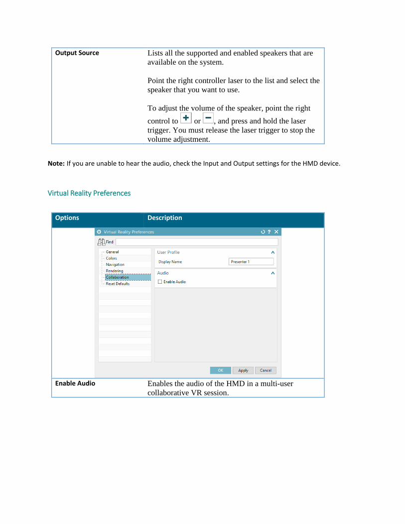
Virtual Reality Preferences
Options Description
Enable Audio Enables the audio of the HMD in a multi-user
collaborative VR session.
CMM: Multiple Curve Segments for Curve Scan
Introduction
CMM Inspection – Path Dialog – Curve Scans When programming curve scans the user can define scan parameters such as scan speed at each control
point. In NX1903, the user has two new ways to define the control points:
- Midpoint of curve
- Screen select point on curve
Line Designer: Native Mode Support
Introduction
Working with a plant layout in NX managed and native mode
What is it?
In the native Line Designer application, you can now modify the plant layout to add resources. Also, you
can create detailed designs. You can:
● Add, remove, and modify the components of a plant layout. For example, use the NX Modeling application to create new components.
● Display the attributes of the component files in the Plant Navigator.
● Add, edit, and remove attributes of the components in the Properties dialog box and in the Plant Navigator for configured columns.
● Save the modified plant structure data in NX native mode, and optionally update the plant layout in the NX Managed mode.
● Work with connections, attachments, mounts, and kinematic objects.
Why should I use it?
You can now author Line Designer plant layouts in NX native.
Where do I find it?
Application Line Designer
Resource bar File tab→Export Assembly outside Teamcenter
File tab→Import Assembly into Teamcenter
Technical documentation
Managing a plant layout in NX managed and native mode
Exporting and importing a plant layout
For various business processes and customer requirements, and for general product development, you
need to move the plant layout from one database to another. This helps you to conveniently provide
required data to a third party for further modifications. To do this, use the Export Assembly outside
Teamcenter command.
You can modify and detail the plant layout and add, remove, modify, rename, and revise its components
in NX native mode.
Once you modify the plant layout, you can import back this data into NX integrated with the Teamcenter
environment. To do this, use the Import Assembly into Teamcenter command. You can verify and validate
the changes to the plant layoutfixture data.
You can move the plant layout data in the following way:
Export Assembly outside Teamcenter
In NX integrated with Teamcenter, you can launch the Plant Navigator and load a plant layout. Before you export the plant layout data, make sure that you do the following:
● Save the plant layout data in Line Designer before you export the data, with or without any changes.
● Confirm that the plant layout data contains part files for all the objects. This is necessary so that Line Designer in the native mode recognizes these objects in the Plant Navigator.
● Use the mapping file to map the object properties to the part file. You can use this mapping file in the NX native mode and show more
information to the native user. To do this, use the attribute mapping tool.
For more information, see Export Assembly outside Teamcenter Overview in NX help.
Import Assembly into Teamcenter
Import the modified plant layout data to NX integrated with Teamcenter. This helps you to validate the plant layout with a detailed plan and to check for the modified data. For more information, see Import Assembly into Teamcenter in NX help.
If the plant layout data contains the JT parts as components, you can export them to NX native in the local directory and import them back in NX integrated with Teamcenter. NX exports the JT parts as components in the plant layout. For more information, see Importing and exporting Multi-CAD in NX help.
Where do I find it?
Application Line Designer
Resource bar File tab→Export Assembly outside Teamcenter
File tab→Import Assembly into Teamcenter
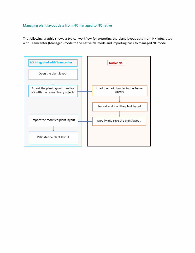
Managing plant layout data from NX managed to NX native
The following graphic shows a typical workflow for exporting the plant layout data from NX integrated
with Teamcenter (Managed) mode to the native NX mode and importing back to managed NX mode.
Managing plant layout data in NX native
The following graphic shows a typical workflow for working with a plant layout in NX native mode.
Managing plant layout data from NX native to NX managed
The following graphic shows a typical workflow for working with a plant layout in NX native mode and
then importing the data in NX integrated with Teamcenter (Managed) mode.
Managing PAX files for NX Native
A PAX file is actually a palette file with a .pax extension. A palette file is an XML file that contains a list of
palette entries, each of which contains a specific identification number and a standard set of data that
describes the entry.
You can create structure and resource objects that you can load in Teamcenter as a specific Item Type.
The pax file for a work area template in Line Designer is named ugs_linedesigner_workarea_templates.pax
and for the resource templates is named ugs_linedesigner_templates.pax.
The following is an example of the XML in a .pax file that defines the template for the new work area. The
type specified in the object data section is mapped to the Item Type in Teamcenter, which you can use
while importing layout data to Teamcenter.
You can customize the pax files to achieve the work area and resource types you want, regardless of the
listed work areas and resources below.
Supported work areas
By default, these work areas are available to use in NX native:
• Workarea
• Plant
• Site
• Department
• Line
• Zone
• Station
• Blank (Custom)
Supported resource templates
By default, these resource templates are available to use in NX native:
• Equipment
• Resource
• Conveyor
• Robot
• Factory Tool
• Cable Resources
• Sensors
• Fixture Root
• Blank (Custom)
Working with Attribute templates files and icons in native NX
Icons from item types
When you work in a plant layout, you can see the component icons in the Plant Navigator
based on the Item Type definition that you specify in the part file. This helps you identify
the different types of work areas and resources in the layout.
You can customize the default icons to use the desired bmp or png files and to align with
the Item Types and with the icons that are available in Teamcenter.
You can also display customized icons in the Plant Navigator for the default Item Types
included with Line Designer or for custom Item Types. To do this, you must store the
respective .bmp or .png files in the installation folder.
The Attribute Templates are based on the attribute mappings that you define in
Teamcenter. You can export these templates from NX and customize them. For more
information, see Attribute templates in NX help. For detailed information about the mapping file, see Mapping Attributes in Teamcenter
and Teamcenter Integration in NX help.
Modifying the plant layout in NX native
To align with changing customer requirements, you might need to frequently change the design of a plant
layout. This helps you create new designs, develop new products, and stay current in the market.
You can modify the plant layout to add components. Also, you can create detailed designs. To do this, you
can use the Line Designer in NX native mode.
You can export the plant layout from NX managed mode to the NX native mode and load the whole plant
layout structure.
When you load the plant layout data in NX native, you can:
● Add, remove, and modify the components of a plant layout. For example, use the NX Modeling application to create new components.
● Display the attributes of the component files in the Plant Navigator.
● Add, edit, and remove attributes of the components using the Properties dialog box and in the Plant Navigator for configured columns.
● Save the modified plant structure data in NX native mode, and optionally update the plant layout in the NX Managed mode.
Work with connections, attachments, mounts, and kinematic objects.
CAE: Pre/Post for Ansys
Introduction
Importing All KEYOPTs as User Defined KEYOPTs
Many ANSYS element types have key options (KEYOPTs) that you can specify. Each KEYOPT is identified by its number and may have different values. For example in ANSYS version 19.1, SHELL181 has 7 KEYOPTs: KEYOPT(1), (3), (5), (8), (9), (10) and (11). The value of KEYOPT(3) could be 0 or 2. The KEYOPT numbers and its values are defined in the XML. They can be changed, removed or added in ANSYS from release to release. When a particular KEYOPT is supported by Pre/Post, but one of its values is unsupported, this value is lost on import, and Pre/Post uses the default value instead. You can now select a new Customer Default, “Import all KEYOPTS as user defined KEYOPTS”, to ensure that unsupported KEYOPT values are imported.
Accessibility You can select this new option from the Customer Defaults dialog box as follows: Customer Defaults → Simulation → Pre/Post → ANSYS → Import →General Options (see the image). Image: Toggle of “Import all KEYOPTS as user defined KEYOPTS” in Customer Defaults
Import behavior
How Pre/Post imports KEYOPTs in an ANSYS input file depends on whether the new customer default is
selected:
• When the new default is turned off, Pre/Post imports KEYOPTs into Pre/Post as in previous releases.
• When the new default is selected, Pre/Post imports all KEYOPTs as User Defined KEYOPTs.
The following images illustrate these two behaviors:
Image: KEYOPTs numbers and values example for SOLID186 with an unsupported value in the input file
Image: SOLID186 ET modeling object with the loss of unsupported value when the customer default is
turned off
Image: SOLID186 ET modeling object when the customer default is selected
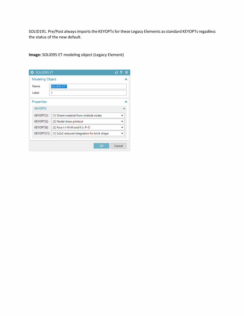
Note: This support applies to all element types accept the Legacy Elements that are not supported as user
defined KEYOPTS. The Legacy Elements are BEAM4, BEAM44, LINK8, LINK10, CONTAC12, CONTAC52,