NX-V680C_DS_EN_201811_Q287I-E-01 1 NX-series RFID Units NX-V680C V680 RFID reader/writers enable faster and more consistent field networks, supports NX controller distribution, and provide better traceability • The NX series of CPU Units support direct connectivity, features built-in EtherCAT Coupler Units and EtherNet/IP TM Coupler Units, and can connect directly to the globally deployable RFID V680 series of devices • Supports burst communication of 8-kbytes data Features • Data reads/writes are easily performed by simply setting parameters in the machine automation controller memory area. • Simple device configuration, compared to serial communication, coupled with high-speed data processing. • Communication programs can be easily built using the ladder program function blocks "Sysmac Library RFID Communications Library (SYSMAC-XR019)". Note: Refer to the V680 series catalog (Q266) and V680 series data sheet (Q267) for more information on RFID system V680 series system configurations. Refer to the corresponding manual of each controller for more information on controller specifications. System Configurations Connected to a CPU Unit The following figure shows a system configuration when a group of NX Units, such as NX-V680C, are connected to an NX-series CPU Unit. NX-series CPU Unit Support Software Sysmac Studio Built-in EtherCAT port Connect to built-in EtherNet/IP port NX Units ● CPU Rack NX1P2-or NX102-End Cover Sysmac is a trademark or registered trademark of OMRON Corporation in Japan and other countries for OMRON factory automation products. EtherCAT ® is a registered trademark and patented technology, licensed by Beckhoff Automation GmbH, Germany. • EtherNet/IP TM is a trademark of ODVA. Other company names and product names in this document are the trademarks or registered trademarks of their respective companies.
Transcript
NX-V680C_DS_EN_201811_Q287I-E-01
1
NX-series RFID Units
NX-V680CV680 RFID reader/writers enable faster and more consistent field networks, supports NX controller distribution, and provide better traceability
• The NX series of CPU Units support direct connectivity, features built-in
EtherCAT Coupler Units and EtherNet/IPTM Coupler Units, and can
connect directly to the globally deployable RFID V680 series of devices
• Supports burst communication of 8-kbytes data
Features• Data reads/writes are easily performed by simply setting parameters in the machine automation controller memory area.• Simple device configuration, compared to serial communication, coupled with high-speed data processing.• Communication programs can be easily built using the ladder program function blocks "Sysmac Library RFID Communications Library
(SYSMAC-XR019)".Note: Refer to the V680 series catalog (Q266) and V680 series data sheet (Q267) for more information on RFID system V680 series system
configurations.Refer to the corresponding manual of each controller for more information on controller specifications.
System Configurations
Connected to a CPU UnitThe following figure shows a system configuration when a group of NX Units, such as NX-V680C, are connected to an NX-series CPU Unit.
NX-series CPU Unit
Support SoftwareSysmac Studio
Built-in EtherCAT port
Connect to built-in EtherNet/IP port
NX Units
● CPU Rack
NX1P2-������ or NX102-���
End Cover
Sysmac is a trademark or registered trademark of OMRON Corporation in Japan and other countries for OMRON factory automation products.
EtherCAT® is a registered trademark and patented technology, licensed by Beckhoff Automation GmbH, Germany.
• EtherNet/IPTM is a trademark of ODVA.
Other company names and product names in this document are the trademarks or registered trademarks of their respective companies.
NX-V680C
2
Connected to an EtherCAT Coupler UnitThe following figure shows an example of the system configuration when an EtherCAT Coupler Unit is used as a Communications Coupler Unit.
*1. The term Support Software indicates software that is provided by OMRON. If you connect to a master from another company, use the software tool corresponding to that master.
*2. An EtherCAT Slave Terminal cannot be connected to any of the OMRON CJ1W-NC81/82 Position Control Units even though they can operate as EtherCAT masters.
EtherCAT master *2
Communications cableEthernet cables
NX-series EtherCAT Coupler UnitNX-ECC20�
● EtherCAT Slave Terminal
Support Software *1
Support Software
ESI files
End Cover
NX Unit
EtherCAT port
ESI files
Connection to peripheral USB port on EtherCAT Coupler Unit
Peripheral USB port
.xml
.xml
NJ/NX-series CPU Unit, NY-series Industrial PC, or master from another manufacturer
3
NX-V680C
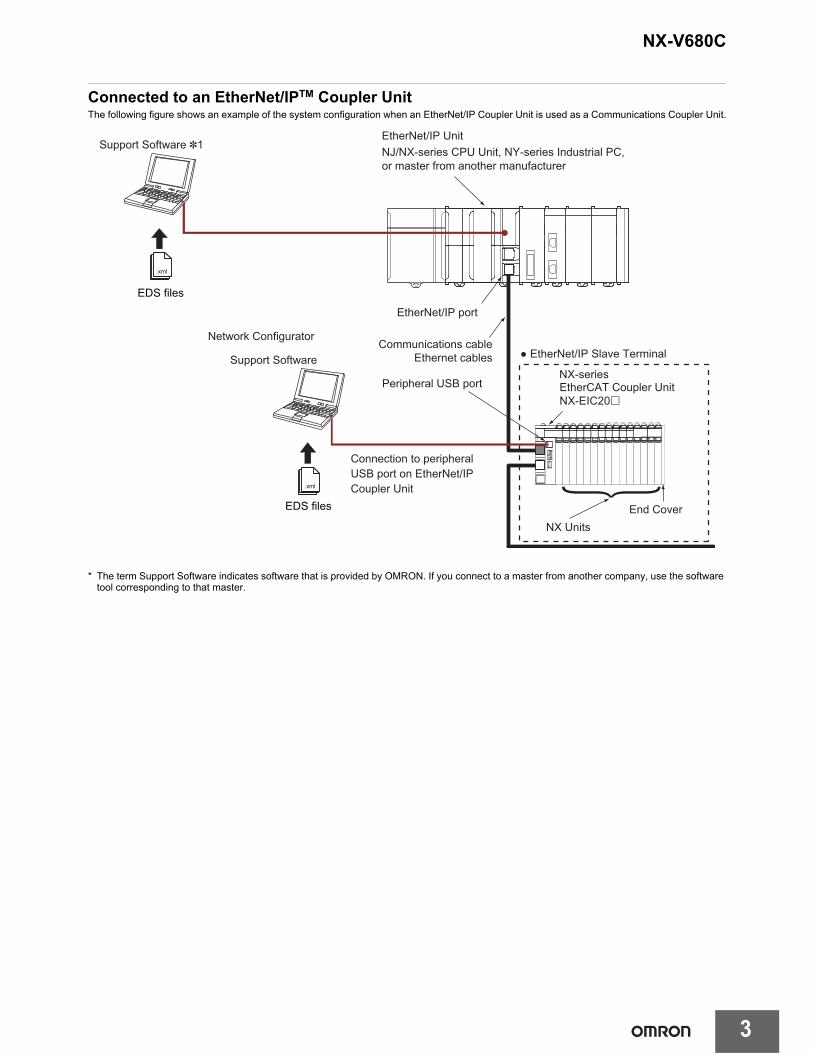
Connected to an EtherNet/IPTM Coupler UnitThe following figure shows an example of the system configuration when an EtherNet/IP Coupler Unit is used as a Communications Coupler Unit.
* The term Support Software indicates software that is provided by OMRON. If you connect to a master from another company, use the software tool corresponding to that master.
EtherNet/IP Unit
Communications cableEthernet cables
EtherCAT Coupler UnitNX-EIC20�
● EtherNet/IP Slave Terminal
Support Software *1
Support Software
Network Configurator
EDS files
End CoverNX Units
NX-series
EtherNet/IP port
EDS files
Connection to peripheral USB port on EtherNet/IP Coupler Unit
Peripheral USB port
.xml
.xml
NJ/NX-series CPU Unit, NY-series Industrial PC, or master from another manufacturer
NX-V680C
4
Ordering InformationApplicable standards
Refer to the OMRON website (www.omron247.com) or ask your OMRON representative for the most recent applicable standards for each model.
RFID Units
RFID Units Appearance Product name Amplifier/AntennaNumber of Antennas/Amplifiers
connectedModel
NX-seriesRFID Units
RFID Units V680 series
1 NX-V680C1
2 NX-V680C2
5
NX-V680C
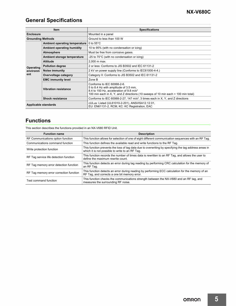
General Specifications
FunctionsThis section describes the functions provided in an NX-V680 RFID Unit.
Item Specifications
Enclosure Mounted in a panel
Grounding Methods Ground to less than 100 W
Operating environment
Ambient operating temperature 0 to 55°C
Ambient operating humidity 10 to 95% (with no condensation or icing)
Atmosphere Must be free from corrosive gases.
Ambient storage temperature -25 to 70°C (with no condensation or icing)
Altitude 2,000 m max.
Pollution degree 2 or less: Conforms to JIS B3502 and IEC 61131-2
Noise immunity 2 kV on power supply line (Conforms to IEC61000-4-4.)
Overvoltage category Category II: Conforms to JIS B3502 and IEC 61131-2
EMC immunity level Zone B
Vibration resistance
Conforms to IEC 60068-2-6.5 to 8.4 Hz with amplitude of 3.5 mm,8.4 to 150 Hz, acceleration of 9.8 m/s2
100 min each in X, Y, and Z directions (10 sweeps of 10 min each = 100 min total)
Shock resistance Conforms to IEC 60068-2-27, 147 m/s2, 3 times each in X, Y, and Z directions
RF Communications option function This function allows for selection of one of eight different communication sequences with an RF Tag.
Communications command function This function defines the available read and write functions to the RF Tag.
Write protection functionThis function prevents the loss of tag data due to overwriting by specifying the tag address areas in which it is not possible to write to an RF Tag.
RF Tag service life detection functionThis function records the number of times data is rewritten to an RF Tag, and allows the user to define the maximum rewrite count.
RF Tag memory error detection functionThis function detects an error during tag reading by performing CRC calculation for the memory of an RF Tag.
RF Tag memory error correction functionThis function detects an error during reading by performing ECC calculation for the memory of an RF Tag, and corrects a one bit memory error.
Test command functionThis function checks the communications strength between the NX-V680 and an RF tag, and measures the surrounding RF noise.
TS indicator, RF indicator, NORM indicator, and ERR indicator
Communications protocol ISO/IEC18000-3 (15693)
Connectable AntennasV680-seriesAntenna with Separate Amplifier: V680-HS
Applicable RF TagsV680S-series RF or V680-series RF Tags
RF Tag reading/writing size 8,192 bytes max.
Divided data size 16 to 128 bytes
Backup function Supported.
Dimensions30 mm (W) x 100 mm (H) x 71 mm (D)
Isolation method Digital isolator isolation
Insulation resistance20 MW min. between isolated circuits (at 100 VDC)
Dielectric strength510 VAC between isolated circuits for 1 minute with a leakage current of 5 mA max.
I/O power supply method Supplied from the NX bus.Current consumption from I/O power supply
V680-HA63 connection380 mA max
NX Unit power consumption
• Connected to a CPU Unit1.00 W max.
• Connected to Communications Coupler Unit0.90 W max.
Current consumption from I/O power supply
130 g max.
Installation orientation and restrictions
Installation orientation:• Connected to a CPU Unit
Possible in upright installation.• Connected to a Communications Coupler Unit
Possible in 6 orientations
Restrictions: No restrictions
NX-V680C
8
Version Information
Connected to a CPU UnitRefer to the user's manual for the CPU Unit for the models of CPU Unit to which RFID Units can be connected.
Connected to an EtherCAT Coupler Unit
* When connecting with other manufacturer's master, use the EtherCAT Coupler Unit with unit version Ver.1.5 or later.
Connected to an EtherNet/IP Coupler Unit
*1. Refer to the user's manual of the EtherNet/IP Coupler Unit for the unit versions of EtherNet/IP Units corresponding to EtherNet/IP Coupler Units.
*2. Refer to the user's manual of the EtherNet/IP Coupler Unit for the unit versions of CPU Units and EtherNet/IP Units corresponding to EtherNet/IP Coupler Units.
NX Units, Corresponding unit versions/versions
ModelUnits
VersionsCPU Units Sysmac Studio
NX-V680C1Ver. 1.0 Version 1.13 or higher Version 1.25 or higher
NX-V680C2
NX Unit Corresponding unit versions/versions
Model Unit VersionEtherCAT Couplers
UnitsCPU Unit or
Industrial PCSysmac Studio
NX-V680C1Ver. 1.0 1.0 or later * 1.05 or higher Version 1.25 or higher
NX-V680C2
NX Unit Corresponding unit versions/versions
Model Unit VersionUse with an NJ/NX/NY-series Controller *1 Use with an CS/CJ/CP-series PLC *2
EtherNet/IP Coupler Unit
CPU Unit or Industrial PC
Sysmac StudioEtherNet/IP
Coupler UnitSysmac Studio
NX-IO Configurator
NX-V680C1Ver. 1.0
Version 1.2 or later
Version 1.14 or later
Version 1.25 or higher
Version 1.2 or later
Version 1.25 or higher
Version 1.13 or laterNX-V680C2
9
NX-V680C
Parts and NamesNX-V680C1 One-channel RFID Unit
NX-V680C2 Two-channel RFID Unit
Letter Name Function
(A) Marker attachment locationsThe locations where markers are attached. The markers made by OMRON are installed for the factory setting. Commercially available markers can also be installed.
(B) NX bus connector This connector is used to connect each Unit.
(C) Unit hookup guides These guides are used to connect two Units.
(D) DIN Track mounting hooks These hooks are used to mount the Unit to a DIN Track.
(E) Protrusions for removing the Unit The protrusions to hold when removing the Unit.
(F) LED Indicators The indicators show the current operating status of the Unit.
(G) Test switchThis is used to switch between the normal mode and the test mode.The test switch can be used when it has been enabled in the Unit operation settings.
(H) Amplifier/antenna connector This is a connector for connecting a V680-series amplifier or antenna (with a built-in amplifier).
(I) FG terminal This is an external connection terminal for grounding. It is shaped like a screwless clamping terminal.
(J) Unit specifications The specifications of the Unit are given.
(K) DIN Track Contact Plates This plate is connected internally to the functional ground terminal on the terminal block.
(B)
(K)(J)
(A)
(B)(B) (C)(D)
(C)(E)
(F)
(C)(E)(C)
(G)
(H)(I)
(A)
(J)
(B) (C)
(C)(E)
(G)
(H)
(C)(E)(C)
(F)
(I)
(B)
(K)
(D)
NX-V680C
10
Wiring the FG TerminalAn RFID Unit has a functional ground terminal (FG terminal), which requires grounding. However, if the material of DIN Track to mount CPU Rack or Slave Terminals are made of steel and the surface is not insulated, you can omit the grounding wire to the FG terminal of the RFID Unit. This is because the functional ground terminal of the RFID Unit is electrically connected to the DIN Track through the DIN Track contact plate.
Wires Applicable to the FG TerminalThe wires that you can connect to the FG terminal block are twisted wires, solid wires, and ferrules that are attached to the twisted wires. The following section describes the dimensions and processed methods for applicable wires.
Dimensions of Wires Connected to the FG Terminal BlockThe dimensions of wires that you can connect into the terminal holes of the FG terminal block are as in the figure below.Process the applicable wires that are specified in the following description to apply the dimensions.
Using FerrulesIf you use ferrules, attach the twisted wires to them.Observe the application instructions for your ferrules for the wire stripping length when attaching ferrules.Always use plated one-pin ferrules. Do not use unplated ferrules or two-pin ferrules.The applicable ferrules, wires, and crimping tools are listed in the following table.
* Some AWG14 wires exceed 2.0 mm2 and cannot be used in the FG terminal block.
When you use any ferrules other than those in the above table, crimp them to the twisted wires so that the following processed dimensions are achieved.
Using Twisted Wires/Solid WiresIf you use twisted wires or solid wires, use the following table to determine the correct wire specifications.
Manufacturer Ferrule model Applicable wire (mm2 (AWG)) Crimping tool
Phoenix Contact Al2.5-10 2.0 *Phoenix Contact (The figure in parentheses is the applicable wire size.)CRIMPFOX 6 (0.25 to 6 mm2, AWG24 to 10)
Wire type
Wire sizeConductor length(stripping length)
Twisted wires Solid wire
Plated Unplated Plated Unplated
Supported Possible Possible Possible 2.0 mm2 9 to 10 mm
DIN Track contact plate
DIN Track
2.0 mm max.
2.7 mm max.
9 to 10 mm
2.0 mm max. 2.7 mm max.
Conductor length (stripping length)
11
NX-V680C
Dimensions (Unit: mm)
NX-V680C1 (One-channel)
NX-V680C2 (Two-channels)
Related Manual
Model Manual name Application Description
NX-V680CNX-series RFID Units User’s Manual
Learning how to use NX-series RFID Units
The hardware, setup methods, and functions of the NX-series RFID Units are described.
SYSMAC-XR019Sysmac Library User’s Manual for RFID Communications Library
Learning how to use Sysmac Library for RFID Communications Library
The setup methods, and functions of the RFID Communications Library are described.
1.5
10
FG 5
2.4
4.7 5.9
1.530
16
100
74.659
17 dia.
32.3
35.4
(157.2)
71(41.9)
20
15
1.5
10
FG 5
2.4
4.7 5.8
1.5
100
74.6
37.5
21.5
30
16
17 dia.
17 dia.
20
15
(157.2)
71(41.9)
32.3
35.4
OMRON CANADA, INC. • HEAD OFFICEToronto, ON, Canada • 416.286.6465 • 866.986.6766 • www.omron247.com
OMRON ELECTRONICS DE MEXICO • HEAD OFFICEMéxico DF • 52.55.59.01.43.00 • 01-800-226-6766 • [email protected]