86
User's Manual NX series Constant and variable torque Variable Speed Drives for induction motors Subject to changes without notice hHoneywell

User's Manual
NX seriesConstant and variable torque
Variable Speed Drivesfor induction motors
Subject to changes without notice
hHoneywell

REFER TO THE START-UP QUICK GUIDE BELOWDURING INSTALLATION AND COMMISSIONING.
IF ANY PROBLEMS OCCUR, PLEASE CONTACT YOUR LOCAL DISTRIBUTOR.
Start-up Quick Guide
1. Check that the product corresponds to your order, see Chapter 3.
2. Read the safety instructions carefully in Chapter 1, before commencingcommissioning.
3. Before the mechanical installation, check the minimum clearances around theunit and check the ambient conditions in Chapter 5.
4. Check the size of the motor cable, mains cable, mains fuses and check thecable connections, read Chapters 6.1.1.1 – 6.1.1.4.
5. Follow the installation instructions, see Chapter 6.1.2.
6. Control cable sizes and the grounding system are explained in Chapter 6.2.1.
7. Select the most appropriate application from the Menu M6, page 6.1.Instructions on using the keypad are given in Chapter 7.
8. Select the language of the keypad from the Menu M6, page 6.2. Instructions onusing the keypad are given in Chapter 7.
9. All parameters have factory default values. In order to ensure proper operation,check the rating plate data for the values below and the correspondingparameters of parameter group G2.1.
• nominal voltage of the motor• nominal frequency of the motor• nominal speed of the motor• nominal current of the motor• motor cosϕ
All parameters are explained in the Application Manual.
10. Follow the commissioning instructions, see Chapter 8.
11. The NX_ Frequency Converter is now ready for use.
The Manufacturer is not responsible for the use of the frequency convertersoutside the instructions provided.
CONTENTS
NX USER’S MANUAL
INDEX
1 SAFETY
2 EU DIRECTIVE
3 RECEIPT OF DELIVERY
4 TECHNICAL DATA
5 INSTALLATION
6 CABLING AND CONNECTIONS
7 CONTROL KEYPAD
8 COMMISSIONING
9 FAULT TRACING
NX APPLICATION MANUAL
1 BASIC APPLICATION
2 STANDARD APPLICATION
3 LOCAL/REMOTE CONTROL APPLICATION
4 MULTI-STEP SPEED CONTROL APPLICATION
5 PID CONTROL APPLICATION
6 MULTI-PURPOSE CONTROL APPLICATION
7 PUMP AND FAN CONTROL APPLICATION

4(86)
THE NX FREQUENCY CONVERTER USER'S MANUALAND THE APPLICATION MANUAL
The User's Manual will provide the necessary information about the installation, commissioningand operation of NX Frequency Converters. It is recommended that these instructions are studied,before powering up the frequency converter for the first time.
The Application Manual provides information about the different applications included in thestandard frequency converter. Should these applications not meet the requirements of theprocess, contact Honeywell for information on special applications.
This manual is available in both paper and electronic editions. It is recommended that theelectronic version be used where possible as it contains several links and cross-references toother locations in the manual which makes it easier for the reader to move around in the manual,to check and find things faster.

5(86)
NX User's Manual
Index
1. SAFETY.................................................................................................................................. 71.1 WARNINGS...................................................................................................................................... 71.2 SAFETY INSTRUCTIONS .................................................................................................................... 71.3 EARTHING AND EARTH FAULT PROTECTION........................................................................................ 81.4 RUNNING THE MOTOR ...................................................................................................................... 8
2. EU DIRECTIVE....................................................................................................................... 92.1 CE MARKING ................................................................................................................................... 92.2 EMC DIRECTIVE .............................................................................................................................. 92.2.1 General ..................................................................................................................................... 92.2.2 Technical criteria ....................................................................................................................... 92.2.3 NX frequency converter EMC classification ............................................................................... 92.2.4 Manufacturer's declaration of conformity ................................................................................. 10
3. RECEIPT OF SHIPMENT..................................................................................................... 123.1 TYPE DESIGNATION CODE............................................................................................................... 123.2 STORAGE...................................................................................................................................... 123.3 MAINTENANCE............................................................................................................................... 133.4 WARRANTY ................................................................................................................................... 13
4. TECHNICAL DATA .............................................................................................................. 144.1 INTRODUCTION .............................................................................................................................. 144.2 POWER RATINGS ........................................................................................................................... 164.2.1 NX5 – Mains voltage 380—500 V............................................................................................ 164.3 TECHNICAL DATA ........................................................................................................................... 17
5. INSTALLATION.................................................................................................................... 195.1 MOUNTING .................................................................................................................................... 195.2 COOLING....................................................................................................................................... 255.3 POWER LOSS................................................................................................................................. 265.3.1 Power loss as function of switching frequency......................................................................... 26
6. CABLING AND CONNECTIONS ......................................................................................... 286.1 POWER UNIT.................................................................................................................................. 286.1.1 Power connections .................................................................................................................. 306.1.1.1 Mains cable ...................................................................................................................... 306.1.1.2 Motor cable....................................................................................................................... 306.1.1.3 Control cable .................................................................................................................... 306.1.1.4 Cable and fuse sizes ........................................................................................................ 316.1.2 Installation instructions ............................................................................................................ 326.1.2.1 Stripping lengths of motor and mains cables..................................................................... 346.1.2.2 NX frequency converter frames and installation of cables................................................. 356.1.3 Cable installation and the UL standards .................................................................................. 396.1.4 Cable and motor insulation checks .......................................................................................... 396.2 CONTROL UNIT .............................................................................................................................. 406.2.1 Control connections................................................................................................................. 406.2.1.1 Control cables................................................................................................................... 426.2.1.2 Galvanic isolation barriers................................................................................................. 426.2.2 Control terminal signals ........................................................................................................... 436.2.2.1 Digital input signal inversions............................................................................................ 44
6(86)
6.2.2.2 Jumper selections on the NXOPTA1 basic board ............................................................. 44
7. CONTROL KEYPAD ............................................................................................................ 467.1 INDICATIONS ON THE KEYPAD DISPLAY ............................................................................................ 467.1.1 Drive status indications............................................................................................................ 467.1.2 Control place indications ......................................................................................................... 477.1.3 Status LEDs (green – green – red) .......................................................................................... 477.1.4 Text lines................................................................................................................................. 487.2 KEYPAD PUSH-BUTTONS ................................................................................................................ 497.2.1 Button descriptions.................................................................................................................. 497.3 NAVIGATION ON THE CONTROL KEYPAD ........................................................................................... 507.3.1 Monitoring menu (M1) ............................................................................................................. 527.3.2 Parameter menu (M2) ............................................................................................................. 537.3.3 Keypad control menu (M3) ...................................................................................................... 567.3.3.1 Selection of control place.................................................................................................. 567.3.3.2 Keypad reference ............................................................................................................. 577.3.3.3 Keypad direction............................................................................................................... 577.3.4 Active faults menu (M4)........................................................................................................... 587.3.4.1 Fault types........................................................................................................................ 587.3.4.2 Fault codes....................................................................................................................... 607.3.4.3 Fault time data record....................................................................................................... 627.3.5 Fault history menu (M5)........................................................................................................... 637.3.6 System menu (M6) .................................................................................................................. 647.3.6.1 Application selection ......................................................................................................... 677.3.6.2 Language selection........................................................................................................... 677.3.6.3 System settings ................................................................................................................ 687.3.6.4 Keypad settings ................................................................................................................ 717.3.6.5 Parameter copy ................................................................................................................ 737.3.6.6 Parameter comparison ..................................................................................................... 757.3.6.7 Information submenu ........................................................................................................ 767.3.6.8 Counters menu ................................................................................................................. 777.3.6.9 Trip counters submenu ..................................................................................................... 787.3.7 Expander board menu (M7)..................................................................................................... 797.4 FURTHER KEYPAD FUNCTIONS ........................................................................................................ 80
8. COMMISSIONING................................................................................................................ 818.1 SAFETY......................................................................................................................................... 818.2 COMMISSIONING OF THE FREQUENCY CONVERTER........................................................................... 81
9. FAULT TRACING................................................................................................................. 84

Safety 7(86)1
1. SAFETY
1.1 Warnings
1 The components of the power unit of the frequency converter are livewhen the NX is connected to mains potential. Contact with this voltageis extremely dangerous and may cause death or severe injury. Thecontrol unit is isolated from the potential.
2 The motor terminals U, V, W and the DC-link/brake resistor terminals –/+are live when the NX is connected to mains, even if the motor is notrunning.
3 The control I/O-terminals are isolated from the mains potential. However,the relay outputs and other I/O-terminals may have a dangerous controlvoltage present even when the NX is disconnected from mains.
4 The frequency converter has a large capacitive leakage current.
5 If the frequency converter is used as a part of a machine, the machinemanufacturer is responsible for providing the machine with a main switch(EN 60204-1).
6 Only spare parts delivered by Honeywell can be used.
1.2 Safety instructions
1 The NX frequency converter is meant for fixed installations only.
2 Do not perform any measurements when the frequency converter isconnected to the mains.
3 After disconnecting the frequency converter from the mains, wait until thefan stops and the indicators on the keypad extinguish. (if no keypad isattached see the indicators on the cover). Wait 5 more minutes beforedoing any work on the NX connections. Do not even open the coverbefore this time has expired.
4 Do not perform any voltage withstand tests on any part of the NX. Thereis a defined procedure for making this test. Ignoring this procedure mayresult in damage to the frequency converter.
5 Prior to measurements on the motor or the motor cable, disconnect themotor cable from the frequency converter.
6 Do not touch the IC-circuits on the circuit boards. Static voltage dischargemay damage the components.
7 Before connecting the frequency converter to mains, ensure that thefrequency converter front and cable covers are closed.
ONLY A COMPETENT ELECTRICIAN SHOULD CARRY OUTTHE ELECTRICAL INSTALLATION
WARNING
8(86) Safety1
1.3 Earthing and earth fault protection
The NX frequency converter must always be earthed via a conductor connected to the earthingterminal .
The earth fault protection inside the frequency converter protects only the converter itself againstearth faults in the motor or the motor cable.
If fault current protective switches (e.g. RCD or Earth Leakage devices) are to be used inconjunction with the frequency converter, they must be tested with earth fault currents that arepossible to arise in fault situations.
1.4 Running the motor
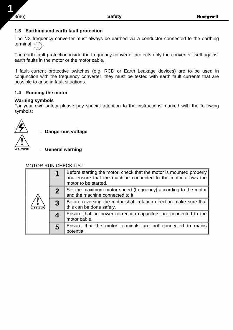
Warning symbolsFor your own safety please pay special attention to the instructions marked with the followingsymbols:
= Dangerous voltage
WARNING = General warning
MOTOR RUN CHECK LIST
1 Before starting the motor, check that the motor is mounted properlyand ensure that the machine connected to the motor allows themotor to be started.
2 Set the maximum motor speed (frequency) according to the motorand the machine connected to it.
3 Before reversing the motor shaft rotation direction make sure thatthis can be done safely.
4 Ensure that no power correction capacitors are connected to themotor cable.
5 Ensure that the motor terminals are not connected to mainspotential.
WARNING

Receipt of delivery 9(86)
2
2. EU DIRECTIVE
2.1 CE marking
The CE marking on the product guarantees the free movement of the product within the EEA(European Economic Area). It also guarantees that the product meets the various requirementsdefined by the directive.The NX frequency converters carry the CE label as a proof of compliance with the Low VoltageDirective (LVD) and the Electro Magnetic Compatibility (EMC). The company SGS FIMKO hasacted as the Competent Body.
2.2 EMC directive
2.2.1 General
The EMC Directive provides that the electrical apparatus must not excessively disturb theenvironment it is used in, and also, it shall have an adequate level of immunity toward otherdisturbances from the same environment.
The compliance of the NX frequency converters with the EMC directive is verified with TechnicalConstruction Files (TCF) checked and approved by SGS FIMKO, which is a Competent Body. TheTechnical Construction Files are used to authenticate the comformity of the NX frequencyconverters with the Directive due to the large product family & variety of installations possibilities.
2.2.2 Technical criteria
The NX frequency converters are marketed throughout the world, a fact which makes the EMCrequirements of customers different. As far as the immunity is concerned, all NX frequencyconverters are designed to fulfil even the strictest requirements, while as regards the emissionlevel, the customer may want to upgrade the NX's already high ability to filter electro-magneticdisturbances.
2.2.3 NX frequency converter EMC classification
The NX frequency converters are divided into three classes, according to the level ofelectromagnetic disturbances emitted. There is no difference in the functions or the controlelectronics between these classes but their EMC properties vary as follows:
Class H:All Vacon NX frequency converters have been designed to fulfil the requirements of theproduct standard EN61800-3 for the 1st environment restricted distribution and the 2ndenvironment.The emission levels correspond to the requirements of EN50081-2.
Class L:The customer has the possibility to upgrade the EMC-disturbance filtering level of the product byordering the frequency converter with external EMC filters. In such case, the frequency convertercomplies with the generic standards EN 50081-1, EN 50081-2 and EN 61800-3, 2ndenvironment (restricted distribution).

10(86) Receipt of delivery
2
Class T:The T-class converters have a small earth current and can be used with IT supplies only. If theyare used with other supplies no EMC requirements are complied with.
Class N:The drives of this class do not provide EMC emission protection. This kind of drives are mountedin enclosures.
All NX frequency converters fulfil all EMC immunity requirements (standards EN 50082-1,50082-2 and EN 61800-3).
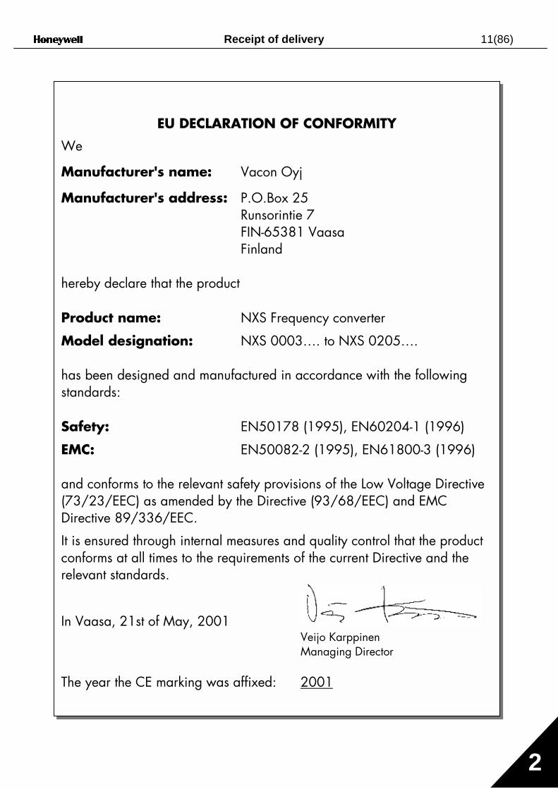
2.2.4 Manufacturer's declaration of conformity
The following pages present the photocopies of the Manufacturer's Declarations of Conformityassuring the compliance of the NX frequency converters with the EMC-directives.
Warning: This is a product of the restricted sales distribution class according to IEC 61800-3. In a domestic environment this product may cause radio interference in which case theuser may be required to take adequate measures.
Receipt of delivery 11(86)
2
EU DECLARATION OF CONFORMITY
We
Manufacturer's name: Vacon Oyj
Manufacturer's address: P.O.Box 25Runsorintie 7FIN-65381 VaasaFinland
hereby declare that the product
Product name: NXS Frequency converter
Model designation: NXS 0003…. to NXS 0205….
has been designed and manufactured in accordance with the followingstandards:
Safety: EN50178 (1995), EN60204-1 (1996)
EMC: EN50082-2 (1995), EN61800-3 (1996)
and conforms to the relevant safety provisions of the Low Voltage Directive(73/23/EEC) as amended by the Directive (93/68/EEC) and EMCDirective 89/336/EEC.
It is ensured through internal measures and quality control that the productconforms at all times to the requirements of the current Directive and therelevant standards.
In Vaasa, 21st of May, 2001Veijo KarppinenManaging Director
The year the CE marking was affixed: 2001
12(86) Receipt of shipment3
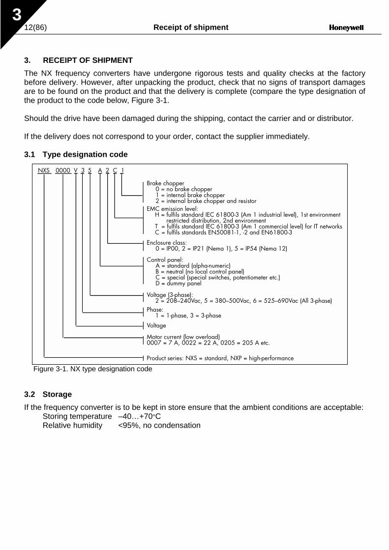
3. RECEIPT OF SHIPMENT
The NX frequency converters have undergone rigorous tests and quality checks at the factorybefore delivery. However, after unpacking the product, check that no signs of transport damagesare to be found on the product and that the delivery is complete (compare the type designation ofthe product to the code below, Figure 3-1.
Should the drive have been damaged during the shipping, contact the carrier and or distributor.
If the delivery does not correspond to your order, contact the supplier immediately.
3.1 Type designation code
Figure 3-1. NX type designation code
3.2 Storage
If the frequency converter is to be kept in store ensure that the ambient conditions are acceptable:Storing temperature –40…+70°CRelative humidity <95%, no condensation
NXS 0000 V 3 5
Motor current (low overload)0007 = 7 A, 0022 = 22 A, 0205 = 205 A etc.
Voltage (3-phase):2 = 208–240Vac, 5 = 380–500Vac, 6 = 525–690Vac (All 3-phase)
Control panel:A = standard (alpha-numeric)B = neutral (no local control panel)C = special (special switches, potentiometer etc.)D = dummy panel
EMC emission level:H = fulfils standard IEC 61800-3 (Am 1 industrial level), 1st environment
restricted distribution, 2nd environmentT = fulfils standard IEC 61800-3 (Am 1 commercial level) for IT networksC = fulfils standards EN50081-1, -2 and EN61800-3
Product series: NXS = standard, NXP = high-performance
Brake chopper0 = no brake chopper1 = internal brake chopper2 = internal brake chopper and resistor
A 2 C 1
Enclosure class:0 = IP00, 2 = IP21 (Nema 1), 5 = IP54 (Nema 12)
Phase:1 = 1-phase, 3 = 3-phase
Voltage

Receipt of shipment 13(86)3
3.3 Maintenance
In normal conditions, the NX frequency converters are maintenance-free. However, it isrecommended the heatsink be cleared periodically with compressed air.The cooling fan can easilybe changed if necessary.
3.4 Warranty
Only manufacturing defects are covered by the warranty. The manufacturer assumes noresponsibility for damages caused during or resulting from transport, receipt of the delivery,installation, commissioning or use.
The manufacturer shall in no event and under no circumstances be held responsible for damagesand failures resulting from misuse, incorrect installation, unacceptable ambient temperature, dust,corrosive substances or operation outside the rated specifications.
Neither can the manufacturer be held responsible for consequential damages.
The Manufacturer's period of warranty is 36 months from the delivery or 24 months from thecommissioning whichever expires first (General Conditions NL92/Orgalime S92).
The local distributor may grant a warranty time different from the above. This warranty period shallbe specified in the distributor's sales and warranty terms. The manufacturer assumes noresponsibility for warranties offered by others.With all warranty issues, please contact thedistributor first.

14(86) Technical data
4
4. TECHNICAL DATA
4.1 Introduction
Figure 4-1 presents the block diagram of the NX frequency converter. The frequency converterconsists of two units, the Power Unit and the Control Unit.The three-phase AC-choke (1) at the mains end together with the DC-link capacitor (2) form anLC-filter, which, again, together with the diode bridge produce the DC-voltage supply to the IGBTInverter Bridge (3) block. The AC-choke also functions as a filter against High Frequencydisturbances from the mains as well as against those caused by the frequency converter to themains. It, in addition, enhances the waveform of the input current to the frequency converter. Theentire power drawn by the frequency converter from the mains is active power.The IGBT Inverter Bridge produces a symmetrical, 3-phase PWM-modulated AC-voltage to themotor.
The Motor and Application Control Block is based on microprocessor software. Themicroprocessor controls the motor basing on the information it receives through measurements,parameter settings, control I/O and control keypad. The motor and application control blockcontrols the motor control ASIC which, in turn, calculates the IGBT positions. Gate drivers amplifythese signals for driving the IGBT inverter bridge.
Figure 4-1. NX block diagram
=
=L 1
L 2
L 3
U
V
W
3~
3~
NK4_1
Mains Motor
BrakeChopper*
Measure-ments
GateDrivers
MotorControlASIC
Motor andApplicationControl
ControlKeypad
Fan
CurrentSensors
RectifierIGBTInverter
Brake resistor*
OutputEMC-filter
PowerSupply
Control I/O
Control I/O
Control I/O
Control I/O
Control I/O
VoltageSensorsNXP
1)
2)
3)
Integrated input module
*Brake resistor is available as optional equipment for all classes (FR4 to FR8).However, the brake resistor can be installed internally in classes FR4 to FR6 and is installedexternally in classes FR7 and greater.Brake chopper belongs to the standard equipment in classes FR4 to FR6, while in greater classes(FR7/FR8) it is optional.
Controlmodule
Powermodule
Charg.res.
Technical data 15(86)
4
The control keypad provides a link between the user and the frequency converter. The controlkeypad is used for parameter setting, reading status data and giving control commands. It isdetachable and can be operated externally and connected via a cable to the frequency converter.Also a PC can be used instead of the control keypad, to control the frequency converter, ifconnected through a similar cable.
Control I/O boards which are either isolated (NXOPTA8) or not isolated (NXOPTA1) from theground are available.
The basic control interface and the parameters (the Basic Application) are easy to use. If a moreversatile interface or parameters are required, a more suitable application can be chosen from theApplication Package. See the Application Manual for more information on the differentapplications.
A brake resistor is available as external or internal option for sizes FR6 and smaller and asexternal option for FR7 and bigger. Optional I/O expander boards that increase the number ofinputs and outputs to be used are also available. For details please contact your nearestHoneywell office or your local distributor (see back cover).
The input and output EMC filters have no influence on the basic functions of the frequencyconverter. They are, however, necessary for the fulfilment of the EMC directives.

16(86) Technical data
4
4.2 Power ratings
4.2.1 NX5 – Mains voltage 380—500 V
High overload = 200% starting torque, 2 sec/20 sec, 150% overloadability, 1 min/10 minLow overload = 150% starting torque, 2 sec/20 sec, 110% overloadability, 1 min/10 min
All sizes up to and including FR8 available with IP21 enclosure and IP54 as option.
Table 4-1. Power ratings and dimensions of the NX, supply voltage 380—500V.
Mains voltage 380-500 V, 50/60 Hz, 3~Frequency
convertertype 10%
overload50%
overload10%
overload50%
overload
40 deg C 50 deg C 40 deg C 50 deg C
P (kW) P (kW) P (kW) P (kW)NXS 0003 3,1 3,5 2,2 3,5 1,1 0,75 1,5 1,1 FR4/IP21, IP54 128x292x190 5NXS 0004 4,0 4,4 3,1 4,4 1,5 1,1 2,2 1,5 FR4/IP21, IP54 128x292x190 5NXS 0005 5,4 6 4 6 2,2 1,5 3 2,2 FR4/IP21, IP54 128x292x190 5NXS 0007 7 7,7 5,4 7,7 3 2,2 4 3 FR4/IP21, IP54 128x292x190 5NXS 0009 9 10 7 10 4 3 5,5 4 FR4/IP21, IP54 128x292x190 5NXS 0012 12 13,2 9 13,2 5,5 4 7,5 5,5 FR4/IP21, IP54 128x292x190 5NXS 0016 16 18 12 18 7,5 5,5 11 7,5 FR5/IP21, IP54 144x391x214 8,1NXS 0022 22 24 16 24 11 7,5 15 11 FR5/IP21, IP54 144x391x214 8,1NXS 0031 31 35 22 35 15 11 18,5 15 FR5/IP21, IP54 144x391x214 8,1NXS 0038 38 47 31 47 18,5 15 22 18,5 FR6/IP21, IP54 195x519x237 18,5NXS 0045 45 54 38 54 22 18,5 30 22 FR6/IP21, IP54 195x519x237 18,5NXS 0061 61 68 45 68 30 22 37 30 FR6/IP21, IP54 195x519x237 18,5NXS 0072 72 92 61 92 37 30 45 37 FR7/IP21, IP54 237x591x257 35NXS 0087 87 108 72 108 45 37 55 45 FR7/IP21, IP54 237x591x257 35NXS 0105 105 131 87 131 55 45 75 55 FR7/IP21, IP54 237x591x257 35NXS 0140 140 158 105 158 75 55 90 75 FR8/IP21, IP54 285x721x288 58NXS 0168 168 210 140 210 90 75 110 90 FR8/IP21, IP54 285x721x288 58NXS 0205 205 252 168 252 110 90 132 110 FR8/IP21, IP54 285x721x288 58
High DimensionsWxHxD Weight10%
overload current
(A)
Rated continuous current IL
(A)
Motor shaft powerMechanical sizeEnclosure and protection class
Rated Continuous current IH
(A)
50% overload current
(A)
380V supply 500V supplyLoadability
Low

Technical data 17(86)
4
4.3 Technical data
Table 4-2. Technical data (continues on next page)
Input voltage Uin
Input frequencyConnection to mainsOutput voltage
Starting torque
Output frequencyFrequency resolutionControl method
Switching frequency(See parameter 2.6.9)
Frequency referenceAnalogue inputPanel referenceField weakening pointAcceleration timeDeceleration timeBraking torque
Ambient operating temperature
Storage temperature
Air quality:- chemical vapours- mechanical particles
5...200 HzDisplacement amplitude 3 mm at 5...10.7 HzMax acceleration amplitude 0.7 G at 10.7...200 Hz
ShockEN50178, IEC 68-2-27
UPS Drop Test (for applicable UPS weights)Storage and shipping: max 15 G, 11 ms (in package)
Ambient conditions
IEC 721-3-3, unit in operation, class 3C2IEC 721-3-3, unit in operation, class 3S2
Altitude 100% load capacity (no derating) up to 1000m1-% derating for each 100m above 1000m; max. 3000m
IP21/NEMA1 standard in entire kW/HP rangeIP54/NEMA12 option in entire kW/HP rangeNote! Keypad installation required for IP54
Enclosure class
–40ºC...+70ºCRelative humidity 0 to 95% RH, non-condensing, non-corrosive,
no dripping water
Vibration (IEC 721-3-3, EN50178/ EN60068-2-6, IEC68-2-6 (68-2-34, -35, -36)
208...240 V; 380...500 V; 525...690 V; -15%...+10%45...66 HzOnce per minute or less (normal case)0—Uin
30...320 Hz0...3000 sec0...3000 sec
Motorconnection IH: Ambient temperature max. +50ºC,
overload 1.5 x IH (1min/10min)IL: Ambient temperature max. +40ºC, overload 1.1 x IL (1min/10min)
150% (Low overload); 200% (High overload)
0...320 Hz (NXS); 7200 Hz (Special)0.01 Hz (NXS); Application dependent (NXP)
Starting current
Mains connection
Continuous output current
DC-brake: 30%*TN (without brake option)
–10ºC (no frost)... +50ºC: IH–10ºC (no frost)... +40ºC: IL
2.5 x IH 2 secs every 20 secs, if output frequency <30Hz and temperature of heatsink <+60ºC (up to 400 kW)
Frequency Control U/fOpen Loop Sensorless Vector ControlClosed Loop Frequency ControlClosed Loop Vector Control (NXP only)
Up to and including NX 0061:1...16 kHz; Factory default 10 kHzFrom NX 0072:1...10 kHz; Factory default 3.6 kHz
Controlcharacteristrics
Resolution 0.1% (10bit), accuracy ±1%Resolution 0.01 Hz

18(86) Technical data
4
Table 4-2. Technical data
Immunity
Safety
Analogue input voltage
Analogue input currentDigital inputs (6)Auxiliary voltageOutput reference voltageAnalogue output
Digital outputs
Overcurrent protection
Overvoltage protectionUndervoltage protection
Mains supervisionMotor phase supervisionUnit overtemperature protectionMotor overload protection Motor stall protectionMotor underload protectionShort-circuit protection of +24V and +10V reference voltages
NX_2: 437V; NX_5: 911V; NX_6: 1200V (all VDC)NX_2: 183V; NX_5: 333V; NX_6: 461V (all VDC)
EMCEmissions
+24V, ±15%, max. 250mA
Relay outputs
Control connections
Trip limit 4.0 * IH instantaneously
+10 V, +3 %, max. load 10 mA
0...+10V, Ri = 200kΩ, (–10V...+10V joystick control)Resolution 0.1%, accuracy ±1%
EMC level H: EN50082-2, EN61800-3 (1st environment, restricted use; 2nd environment)
Fulfil all EMC immunity requirements
EN50178, EN60204-1, CE, UL, cUL, FI,GOST R , IEC 61800-5 (see unit nameplate for more detailed approvals)
0(4)…20mA; RL max 500Ω, Resolution 10 bit, Accur. ±2%
Open collector output, 50mA/48V2 programmable change over relay outputs Max. switching voltage 125Vdc/250VacMax. switching current 6A/24Vdc, 0.4A/250 VacMax. continuous current 2 A rms
0(4)…20mA, Ri = 250Ω differentialPositive or negative logic; 18…24 Vdc
Yes
Yes
Protections
Trips if any of the output phases is missingYes
Yes
Yes
In case of earth fault in motor or motor cable, only the frequency converter is protected
Earth-fault protection
Trips if any of the input phases is missing

Installation 19(86)5
5. INSTALLATION
5.1 Mounting
The frequency converter can be mounted in either vertical or horizontal position on the wall or onthe back plane of a cubicle. Enough space shall be reserved around the frequency converter inorder to ensure a sufficient cooling, see Figure 5-6, Table 5-6 and Table 5-7. For safeinstallation, ensure that the mounting surface is relatively even.The frequency converter should be fixed with four screws (or bolts, depending on the unit size).The dimensions of installation are presented in Figure 5-6 and Table 5-6.
Lift units bigger than FR7 out of the package using a jib crane. Ask the factory or your localdistributor for information on how to lift the unit safely.
Below are the dimensions of the NX frequency converters with IP21 enclosure in Figure 5-1 andwith IP21 for collar installation in Figure 5-2. The dimensions of the opening needed in collarinstallation are given in Table 5-3 and Table 5-5.

20(86) Installation5
Figure 5-1. NX dimensions, IP21
DimensionsTypeW1 W2 H1 H2 H3 D1 ∅ E1∅ E2∅ *
0004—0015 NX20003—0012 NX50005—0019 NX6
128 100 327 313 292 190 7 3 x 28,3
0018—0032 NX20016—0031 NX50022—0035 NX6
144 100 419 406 391 214 7 2 x 37 1 x 28,3
0048—0092 NX20038—0061 NX50042—0085 NX6
195 148 558 541 519 237 9 3 x 37
0120—0150 NX20072—0105 NX50085—0122 NX6
237 190 630 614 591 257 9 3 x 47
0140—0205 NX5 285 255 755 732 721 288 9 3 x 59
Table 5-1. Dimensions for different frequency converter types, IP21
W1
W2
H1 H2
Ø
D1
H3
fr5ip21.fh8
Ø

Installation 21(86)5
Figure 5-2. NX dimensions, IP21 with collar, FR4 to FR6
DimensionsTypeW1 W2 H1 H2 H3 H4 H5 D1 D2 ∅
0004—0015 NX_20003—0012 NX_50005—0019 NX_6
128 113 337 325 327 30 22 190 77 7
0018—0032 NX_20016—0031 NX_50022—0035 NX_6
144 120 434 420 419 36 18 214 100 7
0048—0092 NX_20038—0061 NX_50042—0085 NX_6
195 170 560 549 558 30 20 237 106 6.5
Table 5-2. Dimensions for different frequency converter types FR4 to FR6, IP21 with collar
W2
H1 H2
W1
D1
D2
H4
H5
fr5ip21kaulus.fh8Ø
H3

22(86) Installation5
Figure 5-3. The opening needed for the collar installation, FR4 to FR6
TypeW1 W2 W3 H1 H2 H3 H4 ∅
0004—0015 NX_20003—0012 NX_50005—0019 NX_6
123 113 – 315 325 – 5 6.5
0018—0032 NX_20016—0031 NX_50022—0035 NX_6
135 120 – 410 420 – 5 6.5
0048—0092 NX_20038—0061 NX_50042—0085 NX_6
185 170 157 539 549 7 5 6.5
Table 5-3. Dimensions for the collar opening, FR4/FR5
fr6aukko.fh8
W2
H2
H1
W1W3
H3
Ø
H4

Installation 23(86)5
Figure 5-4. NX dimensions, IP21 with collar, FR7 and FR8
TypeW1 W2 W3 W4 H1 H2 H3 H4 H5 H6 H7 D1 D2 ∅
0120—0150 NX_20072—0105 NX_50085—0122 NX_6
237 175 270 253 652 632 630 188.5 188.5 23 20 257 117 5.5
0140—0205 NX_5 285 – 355 330 832 – 745 258 265 43 57 288 110 9Table 5-4. Dimensions for different frequency converter types FR7 and FR8, IP21 with collar
W3
W1
W2
H1 H2
H3
D1
D2H4
H4
H5
H7W4
H6
fr7kaulusip21.fh8

24(86) Installation5
Figure 5-5. The opening needed for the collar installation, FR7/FR8
TypeW1 W2 W3 H1 H2 H3 H4 H5 H6 ∅
0120—0150 NX_20072—0105 NX_50085—0122 NX_6
233 175 253 619 188.5 188.5 34.5 32 7 5.5
0140—0205 NX_5 301 – 330 810 258 265 – – – 9
Table 5-5. Dimensions for the collar opening, FR7/FR8
W1 W2
H1
H2 H2 H3 H4H5
H6
Ø
W3
fr7aukko.fh8
Installation 25(86)5
C
A
NK5_2
A2 A2
D
B
A
B
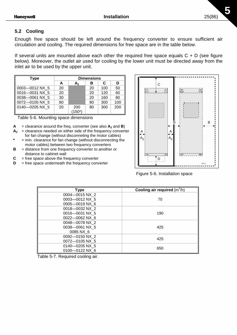
5.2 Cooling
Enough free space should be left around the frequency converter to ensure sufficient aircirculation and cooling. The required dimensions for free space are in the table below.
If several units are mounted above each other the required free space equals C + D (see figurebelow). Moreover, the outlet air used for cooling by the lower unit must be directed away from theinlet air to be used by the upper unit.
Type DimensionsA A2 B C D
0003—0012 NX_5 20 20 100 500016—0031 NX_5 20 20 120 600038—0061 NX_5 30 20 160 800072—0105 NX_5 80 80 300 1000140—0205 NX_5 20 200
(150*)80 300 200
Table 5-6. Mounting space dimensions
Figure 5-6. Installation space
Type Cooling air required [m3/h)0004—0015 NX_20003—0012 NX_50005—0019 NX_6
70
0018—0032 NX_20016—0031 NX_50022—0062 NX_6
190
0048—0078 NX_20038—0061 NX_5
0085 NX_6425
0092—0150 NX_20072—0105 NX_5
425
0140—0205 NX_50100—0122 NX_6 650
Table 5-7. Required cooling air.
A = clearance around the freq. converter (see also A2 and B)A2 = clearance needed on either side of the frequency converter
for fan change (without disconneting the motor cables)* = min. clearance for fan change (without disconnecting the
motor cables) between two frequency convertersB = distance from one frequency converter to another or
distance to cabinet wallC = free space above the frequency converterD = free space underneath the frequency converter

26(86) Installation5
5.3 Power loss
5.3.1 Power loss as function of switching frequency
If the operator wants to raise the switching frequency of the drive for some reason (typically e.g. inorder to reduce the motor noise), this inevitably affects the output power reducing it according tothe graphs below.
Figure 5-7. Power loss as function of switching frequency; 0003…0012NX5
Figure 5-8. Power loss as function of switching frequency; 0016…0031NX5
0,00
20,00
40,00
60,00
80,00
100,00
120,00
140,00
160,00
180,00
200,00
0,00 2,00 4,00 6,00 8,00 10,00 12,00 14,00 16,00
Switching frequency [kHz]
P [
W]
0003NX5 400V
0004NX5 400V 0005NX5 400V 0007NX5 400V0009NX5 400V 0012NX5 400V
0,00
100,00
200,00
300,00
400,00
500,00
600,00
700,00
800,00
900,00
0,00 2,00 4,00 6,00 8,00 10,00 12,00 14,00 16,00
Switching frequency [kHz]
P [
W]
0016NX5 400V
0016NX5 500V 0022NX5 400V 0022NX5 500V0031NX5 400V 0031NX5 500V

Installation 27(86)5
Figure 5-9. Power loss as function of switching frequency; 0038…0061NX5
Figure 5-10. Power loss as function of switching frequency; 0072…0105NX5
0,00
200,00
400,00
600,00
800,00
1000,00
1200,00
1400,00
0,00 2,00 4,00 6,00 8,00 10,00 12,00 14,00 16,00
Switching frequency [kHz]
P [
W]
0038NX5 400V
0038NX5 500V 0045NX5 400V 0045NX5 500V0061NX5 400V 0061NX5 500V
0,00
500,00
1000,00
1500,00
2000,00
2500,00
0,00 2,00 4,00 6,00 8,00 10,00 12,00
Switching frequency [kHz]
P[W
]
0072NX5 400V
0072NX5 500V 0087NX5 400V 0087NX5 500V
0105NX5 400V 0105NX5 500V
28(86) Cabling and connections
6
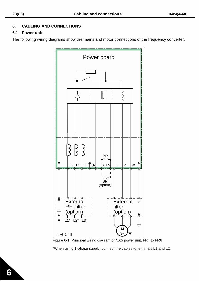
6. CABLING AND CONNECTIONS
6.1 Power unit
The following wiring diagrams show the mains and motor connections of the frequency converter.
Figure 6-1. Principal wiring diagram of NX5 power unit, FR4 to FR6
*When using 1-phase supply, connect the cables to terminals L1 and L2.
U V WB+
M3~
L1* L2* L3
L1 L2 L3
nk6_1.fh8
R-B-
Power board
Externalfilter(option)
ExternalRFI-filter(option)
BR
BR(option)
Cabling and connections 29(86)
6
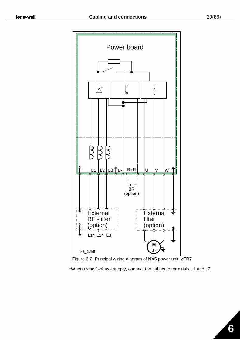
Figure 6-2. Principal wiring diagram of NX5 power unit, ≥FR7
*When using 1-phase supply, connect the cables to terminals L1 and L2.
U V WB+
M3~
L1* L2* L3
L1 L2 L3 B- R-
nk6_2.fh8
Power board
Externalfilter(option)
ExternalRFI-filter(option)
BR(option)
30(86) Cabling and connections
6
6.1.1 Power connections
Use cables with heat resistance of at least +60°C. The cables and the fuses must be dimensionedaccording to the frequency converter nominal OUTPUT current which can be found on the ratingplate. Dimensioning according to the output current is recommended because the frequencyconverter input current never significantly exceeds the output current. Installation of cablesaccording to UL regulations is presented in Chapter 6.1.3.
Table 6-2 shows the minimum dimensions of the Cu-cables and the corresponding GG/GL fusesizes. The dimensions of the fuses in the table have been given taking their function as a cableoverload protection into account.
If the motor temperature protection of the drive (see the Application Manual) is used as anoverload protection, the cable shall be chosen accordingly. If three or more cables are used inparallel for bigger units each cable requires a separate overload protection.
These instructions apply only to cases with one motor and one cable connection from thefrequency converter to the motor. In any other case, ask the factory for more information.
6.1.1.1 Mains cable
Mains cables for different EMC levels in Table 6-1.
6.1.1.2 Motor cable
Motor cables for different EMC levels in Table 6-1.
6.1.1.3 Control cable
For information on control cables see Chapter 6.2.1.1 and Table 6-1.
Cable type Level HMains cable 1Motor cable 2Control cable 4
Table 6-1. Cable types required to meet standards.
Level H = EN 61800-3, 1st environmentEN 50081-2
1 = Power cable intended for fixed installation and thespecific mains voltage. Shielded cable not required.(NNCABLES/MCMK or similar recommended)
2 = Power cable equipped with concentric protection wireand intended for the specific mains voltage.(NNCABLES /MCMK or similar recommended).
3 = Power cable equipped with compact low-impedanceshield and intended for the specific mains voltage.(NNCABLES /MCCMK, SAB/ÖZCUY-J or similarrecommended).
4 = Screened cable equipped with compact low-impedanceshield (NNCABLES /jamak, SAB/ÖZCuY-O or similar).

Cabling and connections 31(86)
6
6.1.1.4 Cable and fuse sizes
Terminal cable size
Frame Type IL[A]
Fuse[A]
Mains andmotorcable
Cu [mm2]
Main terminal[mm2]
Earth terminal[mm2]
FR4 0003—0009 3—9 10 3*1.5+1.5 1—4 1—2.5FR4 0012 12 16 3*2.5+2.5 1—4 1—2.5FR5 0016 16 20 3*4+4 1—10 1—10FR5 0022 22 25 3*6+6 1—10 1—10FR5 0031 31 35 3*10+10 1—10 1—10FR6 0038—45 38—45 50 3*10+10 2.5—50 Cu
6—50 Al6—35
FR6 0061 61 63 3*16+16 2.5—50 Cu6—50 Al
6—35
FR7 0072 72 80 3*25+16 2.5—50 Cu6—50 Al
6—70
FR7 0087 87 100 3*35+16 2.5—50 Cu6—50 Al
6—70
FR7 0105 105 125 3*50+25 2.5—50 Cu6—50 Al
6—70
FR8 0140 140 160 3*70+35 25—95 Cu/Al 25—95FR8 0168 168 200 3*95+50 95—185 Cu/Al 25—95FR8 0205 205 250 3*150+70 95—185 Cu/Al 25—95
Table 6-2. Cable and fuse sizes for NX5
32(86) Cabling and connections
6
6.1.2 Installation instructions
1 Before starting the installation, check that none of the components of thefrequency converter are live.
2 If the frequency converter is installed outside either a switchgear,separate cubicle or electrical room, it must be equipped with a protectioncover (see e.g. Figure 6-4) as provided by the regulations for IP21protection class. For installations in a switchgear, separate cubicle orelectrical room, the cable protection plate is normally not necessary.
3 Place the motor cables sufficiently far from other cables:! Avoid placing the motor cables in long parallel lines with other
cables! If the motor cables runs in parallel with other cables, note the
minimum distances between the motor cables and other cablesgiven in the table below.
! The given distances also apply between the motor cables andsignal cables of other systems.
! The maximum length of the motor cables is 300 m (level H,units with power greater than 1.5 kW) and 100 m (units with powerfrom 0.75 to 1.5 kW).
! The motor cables should cross other cables at an angle of 90degrees.
4 If cable insulation checks are needed, see Chapter 6.1.4.
Distance between cables
[m]
Shielded cable[m]
0.3 ≤501.0 ≤200
Continues on the next page

Cabling and connections 33(86)
6
5 Connect the cables:! Strip the motor and mains cables as advised in Table 6-3 and
Figure 6-3.! Remove the screws of the cable protection plate.! Make holes into and pass the cables through the rubber
grommets on the bottom of the power unit (see e.g. Figure 6-7).! Connect the mains, motor and control cables into their
respective terminals (see e.g. Figure 6-7).! For information on the installation of larger units, please contact
your local distributor.! For Information on cable installation according to UL
regulations see Chapter 6.1.3.! Ensure that the control cable wires do not come in contact with the
electronic components of the unit.! If an external brake resistor (option) is used, connect its cable to
the appropriate terminal.! Check the connection of the earth cable to the motor and the
frequency converter terminals marked with .! Connect the separate shield of the power cable to the earth
terminals of the frequency converter, motor and the supply centre.! Attach the cable protection plate with the screws.! Ensure that the control cables or the cables of the unit are not
trapped between the frame and the protection plate.

34(86) Cabling and connections
6
6.1.2.1 Stripping lengths of motor and mains cables
Figure 6-3. Stripping of cables
Frame A1 B1 C1 D1 A2 B2 C2 D2FR4 15 35 10 20 7 50 7 35FR5 20 40 10 30 20 60 10 40FR6 20 90 15 60 20 90 15 60FR7 25 120 25 120 25 120 25 120FR80140
0168—02052328
240240
2328
240240
2328
240240
2328
240240
Table 6-3. Cables stripping lengths [mm]
nk6141.fh8
MAINS MOTOR
Earthconductor
Earthconductor
D1B1
C1A1
D2B2
C2A2
Cabling and connections 35(86)
6
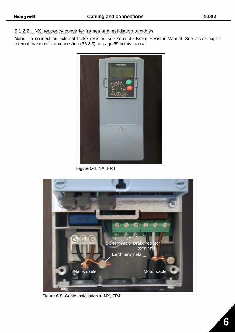
6.1.2.2 NX frequency converter frames and installation of cables
Note: To connect an external brake resistor, see separate Brake Resistor Manual. See also ChapterInternal brake resistor connection (P6.3.3) on page 69 in this manual.
Figure 6-4. NX, FR4
Figure 6-5. Cable installation in NX, FR4
Mains cable Motor cable
Earth terminals
Brake resistorterminals
DC-terminals

36(86) Cabling and connections
6
Figure 6-6. NX, FR5. Protection class IP21
Figure 6-7. Cable installation in NX, FR5
Mains cable Motor cable
Earth terminals
Brake resistorterminals
DC terminals
Cabling and connections 37(86)
6
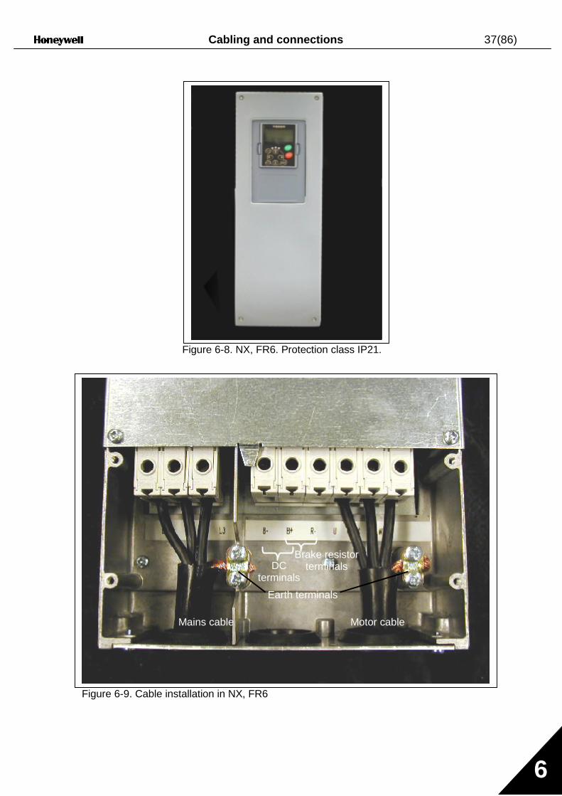
Figure 6-8. NX, FR6. Protection class IP21.
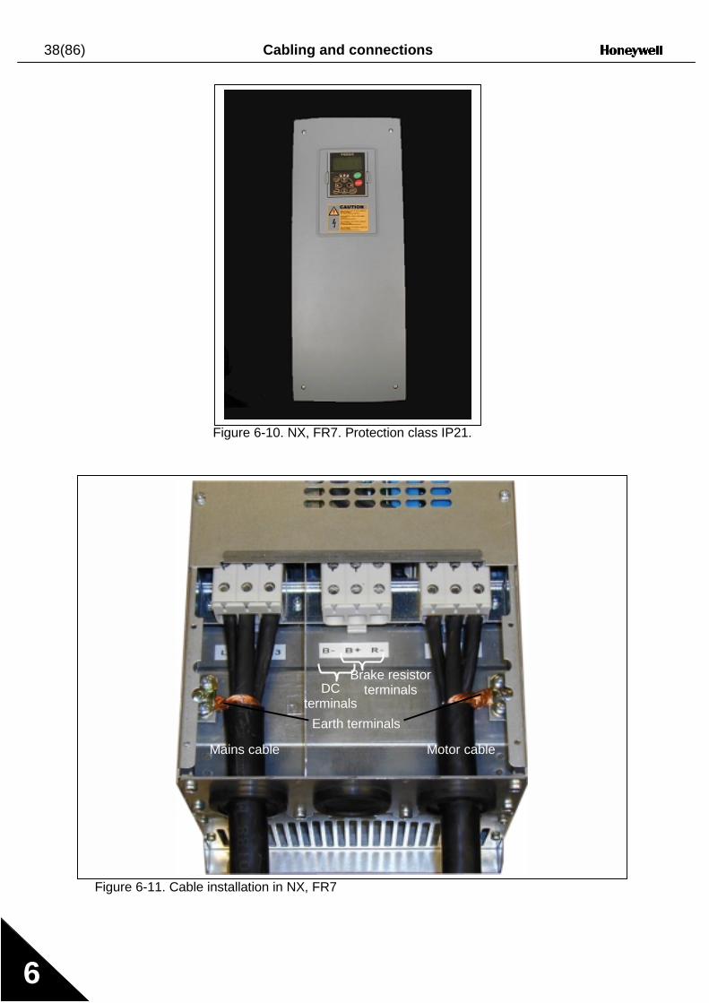
Figure 6-9. Cable installation in NX, FR6
Mains cable Motor cable
Earth
Brake resistorterminals
Brake resistorterminals
Mains cable Motor cable
Earth terminals
DCterminals
38(86) Cabling and connections
6
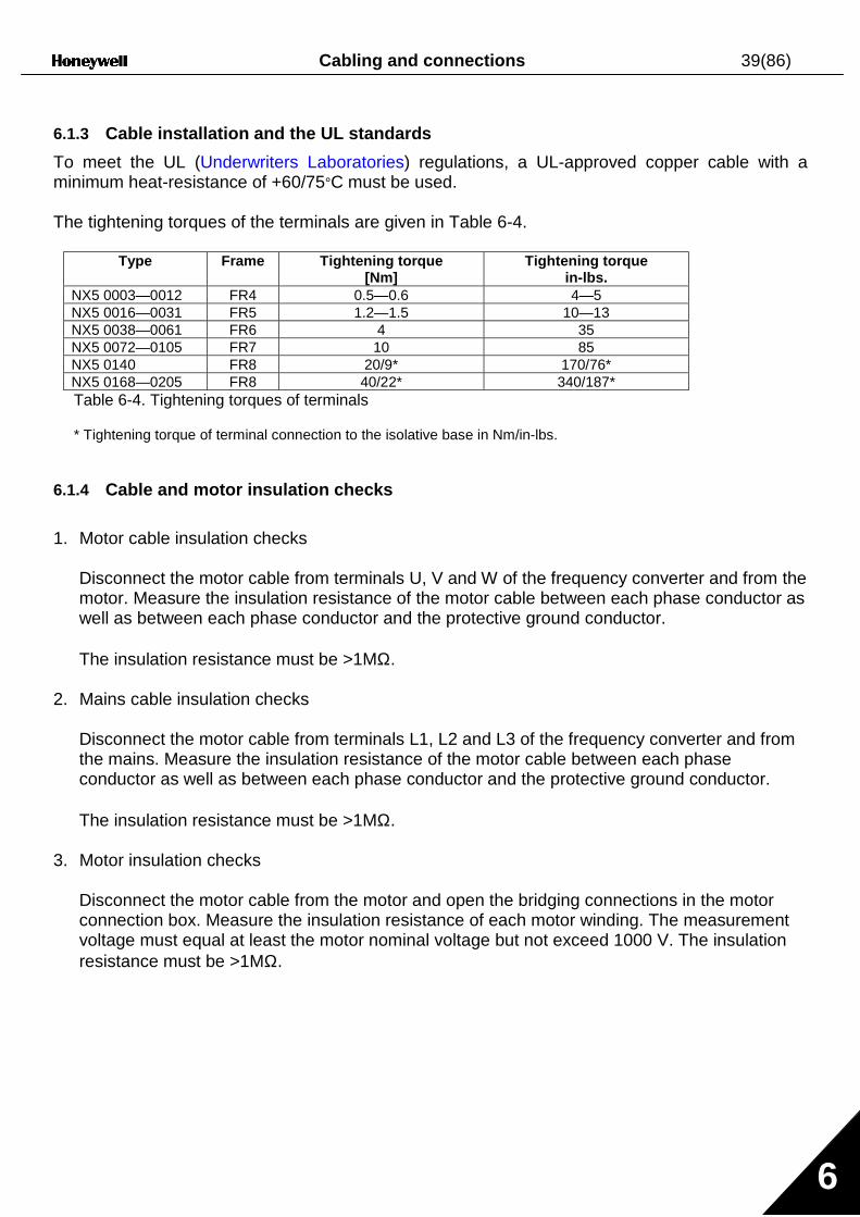
Figure 6-10. NX, FR7. Protection class IP21.
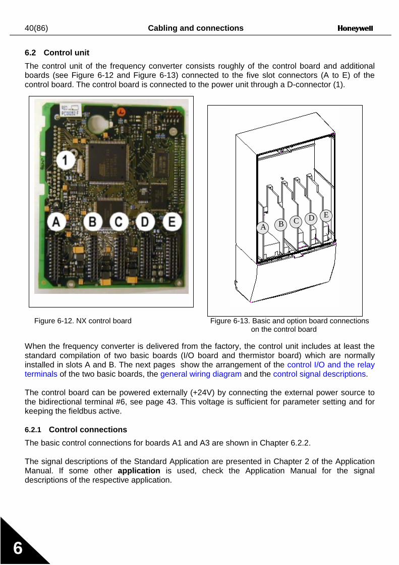
Figure 6-11. Cable installation in NX, FR7
Mains cable Motor cable
Earth terminals
Brake resistorterminalsDC
terminals
Cabling and connections 39(86)
6
6.1.3 Cable installation and the UL standards
To meet the UL (Underwriters Laboratories) regulations, a UL-approved copper cable with aminimum heat-resistance of +60/75°C must be used.
The tightening torques of the terminals are given in Table 6-4.
Type Frame Tightening torque[Nm]
Tightening torquein-lbs.
NX5 0003—0012 FR4 0.5—0.6 4—5NX5 0016—0031 FR5 1.2—1.5 10—13NX5 0038—0061 FR6 4 35NX5 0072—0105 FR7 10 85NX5 0140 FR8 20/9* 170/76*NX5 0168—0205 FR8 40/22* 340/187*Table 6-4. Tightening torques of terminals
* Tightening torque of terminal connection to the isolative base in Nm/in-lbs.
6.1.4 Cable and motor insulation checks
1. Motor cable insulation checks
Disconnect the motor cable from terminals U, V and W of the frequency converter and from themotor. Measure the insulation resistance of the motor cable between each phase conductor aswell as between each phase conductor and the protective ground conductor.
The insulation resistance must be >1MΩ.
2. Mains cable insulation checks
Disconnect the motor cable from terminals L1, L2 and L3 of the frequency converter and fromthe mains. Measure the insulation resistance of the motor cable between each phaseconductor as well as between each phase conductor and the protective ground conductor.
The insulation resistance must be >1MΩ.
3. Motor insulation checks
Disconnect the motor cable from the motor and open the bridging connections in the motorconnection box. Measure the insulation resistance of each motor winding. The measurementvoltage must equal at least the motor nominal voltage but not exceed 1000 V. The insulationresistance must be >1MΩ.
40(86) Cabling and connections
6
6.2 Control unit
The control unit of the frequency converter consists roughly of the control board and additionalboards (see Figure 6-12 and Figure 6-13) connected to the five slot connectors (A to E) of thecontrol board. The control board is connected to the power unit through a D-connector (1).
Figure 6-12. NX control board Figure 6-13. Basic and option board connectionson the control board
When the frequency converter is delivered from the factory, the control unit includes at least thestandard compilation of two basic boards (I/O board and thermistor board) which are normallyinstalled in slots A and B. The next pages show the arrangement of the control I/O and the relayterminals of the two basic boards, the general wiring diagram and the control signal descriptions.
The control board can be powered externally (+24V) by connecting the external power source tothe bidirectional terminal #6, see page 43. This voltage is sufficient for parameter setting and forkeeping the fieldbus active.
6.2.1 Control connections
The basic control connections for boards A1 and A3 are shown in Chapter 6.2.2.
The signal descriptions of the Standard Application are presented in Chapter 2 of the ApplicationManual. If some other application is used, check the Application Manual for the signaldescriptions of the respective application.
A B C D E

Cabling and connections 41(86)
6
Figure 6-14. The I/O terminalsof the two basic boards
Figure 6-15. General wiring diagram of the basic I/O board(NXOPTA1)
Figure 6-16. General wiring diagram of the basic relay board(NXOPTA3)
Board A1in slot A
NXOPTA1
Board A3in slot B
NXOPTA3
RO1/11/2
RO1/3
2/1
RO2/2
RL ac/dc
TI1+
TI1–
212223
25
26
Switching:<8A/24Vdc,<0.4A/300Vdc,<2kVA/250VacContinuously:<2Arms
2829
+10VrefAI1+GNDAI2+AI2-24VoutGNDDIN1DIN2DIN3CMA24VoutGNDDIN4DIN5DIN6CMBAO1+AO1-DO1
1234567891011121314151617181920
24 V
GND
24 V
GND
U<+48VI<50mA
+
0(4)/20mARL<500Ω
nk6_13
Basic I/O boardNXOPTA1
Reference(voltage)
Reference(current)
Dotted line indicates the connection with inverted signals

42(86) Cabling and connections
6
6.2.1.1 Control cables
The control cables shall be at least 0.5 mm2 screened multicore cables, see Table 6-1. Themaximum terminal wire size is 2.5 mm2 for the relay terminals and 1.5 mm2 for other terminals.
6.2.1.2 Galvanic isolation barriers
The control connections are isolated from the mains potential and the GND terminals arepermanently connected to ground. See Figure 6-17.The digital inputs are galvanically isolated from the I/O ground. The relay outputs are additionallydouble-isolated from each other at 300VAC (EN-50178).
Figure 6-17. Galvanic isolation barriers
Control I/Oground
Digital inputgroup A
Digital inputgroup B
AnalogueoutputDigitaloutput
Maincircuits
Controlboard
Controlpanel
Controlboard
nk6_15
L1 L2 L3
U V W
RO1/1RO1/2RO1/3
RO2/3RO2/2RO2/1
10VrefGND
GND+24V
AI1AI2+AI2 -
DIN1...DIN3CMADIN4...DIN6CMBAO1+AO2 -
DO1
Gate drivers

Cabling and connections 43(86)
6
6.2.2 Control terminal signals
Terminal Signal Technical information1 +10 Vref Reference voltage Maximum current 10 mA2 AI1+ Analogue input,
voltage or currentSelection V or mA with jumper block X1 (see page 45):Default: 0– +10V (Ri = 200 kΩ)
(-10V…..+10V Joy-stick control, selected with a jumper)0– 20mA (Ri = 250 Ω)
3 GND/AI1– Analogue input common Differential input if not connected to ground;Allows ±20V differential mode voltage to GND
4 AI2+ Analogue input,voltage or current
Selection V or mA with jumper block X2 (see page 45):Default: 0– 20mA (Ri = 250 Ω)
0– +10V (Ri = 200 kΩ)(-10V…..+10V Joy-stick control, selected with a jumper)
5 GND/AI2– Analogue input common Differential input if not connected to ground;Allows ±20V differential mode voltage to GND
6 24 Vout(bidirectional)
24V auxiliary voltage ±15%, maximum current 250mA (all boards total);150mA(from single board); Can also be used as external powerbackup for the control unit (and fieldbus)
7 GND I/O ground Ground for reference and controls
8 DIN1 Digital input 1
9 DIN2 Digital input 2
10 DIN3 Digital input 3
Ri = min. 5kΩ
11 CMA Digital input common A forDIN1, DIN2 and DIN3.
Must be connected to GND or 24V of I/O terminal orto external 24V or GNDSelection with jumper block X3 (see page 45):
12 24 Vout(bidirectional)
24V auxiliary voltage Same as terminal #6
13 GND I/O ground Same as terminal #714 DIB4 Digital input 415 DIB5 Digital input 516 DIB6 Digital input 6
Ri = min. 5kΩ
17 CMB Digital input common B forDIB4, DIB5 and DIB6
Must be connected to GND or 24V of I/O terminal orto external 24V or GNDSelection with jumper block X3 (see page 45):
18 AO1+ Analogue signal (+output)
19 AO1– Analogue output common
Output signal range:Current 0(4)–20mA, RL max 500Ω orVoltage 0—10V, RL >1kΩSelection with jumper block X6 (see page 45):
20 DO1 Open collector output Maximum Uin = 48VDCMaximum current = 50 mA
NXOPTA3
21 RO1/1
22 RO1/2
23 RO1/3
Relay output 1 Maximum switching voltage 250VAC, 125VDCMaximum switching current8A/24VDC,
0.4A/250VDCMin. switching load 5V/10mA
2526
RO2/1RO2/2
Relay output 2 Maximum switching voltage 250VAC, 125VDCMaximum switching current8A/24VDC, 0.4A/250VDCMin. switching load 5V/10mA
2829
TI1/1TI1/2
Thermistor input 1 Basic galvanic isolationDouble isolation when connected to thermistor
Table 6-5. Control I/O terminal signals

44(86) Cabling and connections
6
6.2.2.1 Digital input signal inversions
The active signal level depends on which potential the common inputs CMA and CMB (terminals11 and 17) are connected to. The alternatives are either +24V or ground (0 V). See Figure 6-18.
The 24-volt control voltage and the ground for the digital inputs and the common inputs (CMA,CMB) can be either internal or external.
Figure 6-18. Positive/Negative logic
6.2.2.2 Jumper selections on the NXOPTA1 basic board
The user is able to customise the functions of the frequency converter to better suit his needs byselecting certain positions for the jumpers on the NXOPTA1 board. The positions of the jumpersdetermine the signal type of analogue and digital inputs.
On the A1 basic board, there are four jumper blocks X1, X2, X3 and X6 each containing eight pinsand two jumpers. The selectable positions of the jumpers are shown in Figure 6-20.
Figure 6-19. Jumper blocks on NXOPTA1
+24V
+24V
DIN1
DIN2
DIN3
CMA
DIN1
DIN2
DIN3
CMAGround
Ground
Positive logic (+24V is the active signal) =the input is active when the switch is closed
Negative logic (0V is the active signal) =the input is active when the switch is closed

Cabling and connections 45(86)
6
Figure 6-20. Jumper selection for NXOPTA1
!WARNING
Check the correct positions of the jumpers. Running the motorwith signal settings different from the jumper positions will notharm the frequency converter but may damage the motor.
!NOTE
If the AI signal content is changed the corresponding boardparameter in menu M7 must also be changed.
A B C D
A B C D
A B C D
A B C D
A B C D
A B C D
A B C D
A B C D
A B C D
A B C D
Jumper block X1:AI1 mode
AI1 mode: Voltage input; 0...10V
AI1 mode: Voltage input; 0...10V (differential)
AI1 mode: Voltage input; -10...10V
Jumper block X2:AI2 mode
AI2 mode: 0...20mA; Current input
AI2 mode: Voltage input; 0...10V
AI2 mode: Voltage input; 0...10V (differential)
AI2 mode: Voltage input; -10...10V
Jumper block X3:CMA and CMB grounding
CMB connected to GNDCMA connected to GND
CMB isolated from GNDCMA isolated from GND
CMB and CMAinternally connected together,isolated from GND
= Factory default
Jumper block X6:AO1 mode
AO1 mode: 0...20mA; Current output
AO1 mode: Voltage output; 0...10V
AI1 mode: 0...20mA; Current input
46(86) Control keypad7
7. CONTROL KEYPAD
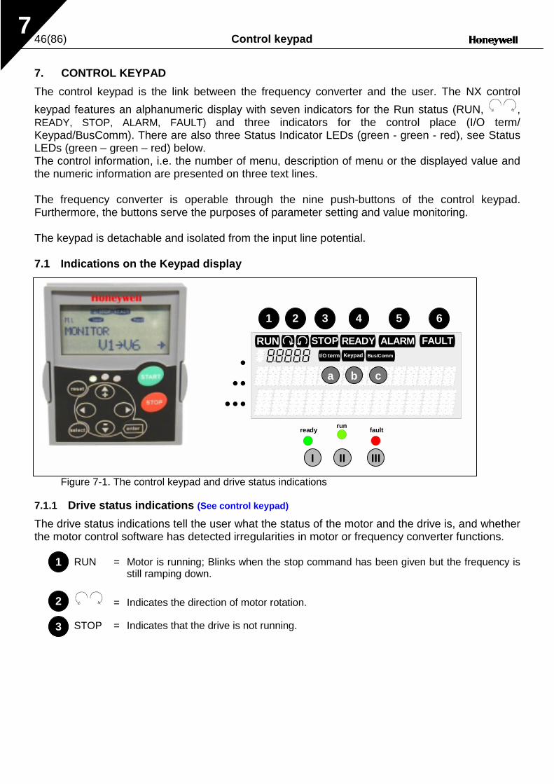
The control keypad is the link between the frequency converter and the user. The NX control
keypad features an alphanumeric display with seven indicators for the Run status (RUN, ,READY, STOP, ALARM, FAULT) and three indicators for the control place (I/O term/Keypad/BusComm). There are also three Status Indicator LEDs (green - green - red), see StatusLEDs (green – green – red) below.The control information, i.e. the number of menu, description of menu or the displayed value andthe numeric information are presented on three text lines.
The frequency converter is operable through the nine push-buttons of the control keypad.Furthermore, the buttons serve the purposes of parameter setting and value monitoring.
The keypad is detachable and isolated from the input line potential.
7.1 Indications on the Keypad display
Figure 7-1. The control keypad and drive status indications
7.1.1 Drive status indications (See control keypad)
The drive status indications tell the user what the status of the motor and the drive is, and whetherthe motor control software has detected irregularities in motor or frequency converter functions.
RUN = Motor is running; Blinks when the stop command has been given but the frequency isstill ramping down.
= Indicates the direction of motor rotation.
STOP = Indicates that the drive is not running.
READY FAULTSTOPRUNBus/CommKeypadI/O term
ALARM
runready fault
1 2 3 4 5 6
a b
I II III
•••
•••
c
1
2
3

Control keypad 47(86)7
READY = Lights when AC power is on. In case of a trip, the symbol will not light up.
ALARM = Indicates that the drive is running outside a certain limit and a warning is given.
FAULT = Indicates that unsafe operating conditions were encountered due to which the drivewas stopped.
7.1.2 Control place indications (See control keypad)
The symbols I/O term, Keypad and Bus/Comm (see Figure 7-1) indicate the choice of controlplace made in the Keypad control menu (M3) (see chapter 7.3.3).
I/O term = I/O terminals are the selected control place; i.e. START/STOPcommands or reference values etc. are given through the I/O terminals.
Keypad = Control keypad is the selected control place; i.e. the motor can bestarted or stopped, or its reference values etc. altered from the keypad.
Bus/Comm = The frequency converter is controlled through a fieldbus.
7.1.3 Status LEDs (green – green – red) (See control keypad)
The status LEDs light up in connection with the READY, RUN and FAULT drive status indicators.
= Illuminates with the AC power connected to the drive. Simultaneously, thedrive status indicator READY is lit up.
= Illuminates when the drive is running. Blinks when the STOP button hasbeen pushed and the drive is ramping down.
= Illuminates when unsafe operating conditions were encountered due towhich the drive was stopped (Fault Trip). Simultaneously, the drive statusindicator FAULT blinks on the display and the fault description can be seen,see chapter 7.3.4, Active Faults.
4
5
6
b
c
a
I
II
III

48(86) Control keypad7
7.1.4 Text lines (See control keypad)
The three text lines (• , •• , ••• ) provide the user with information on his present location in thekeypad menu structure as well as with information related to the operation of the drive.
• = Location indication; displays the symbol and number of menu, parameteretc.Example: M3 = Menu 3 (References); R1 = Reference no. 1 (Freq.reference)
•• = Description line; Displays the description of menu, value or fault.
••• = Value line; Displays the numerical and textual values of references,parameters etc. and the number of submenus available in each menu.

Control keypad 49(86)7
7.2 Keypad push-buttons
The alphanumeric control keypad features 9 push-buttons that are used for the control of thefrequency converter (and motor), parameter setting and value monitoring.
Figure 7-2. Keypad push-buttons
7.2.1 Button descriptions
reset = This button is used to reset active faults (see Chapter 7.3.4).
select = This button is used to switch between two latest displays. May be useful tosee how the changed new value influences some other value.
enter = The Enter button serves for:1) confirmation of selections2) fault history reset (2…3 seconds)
= Browser button upBrowse the main menu and the pages of different submenus.Edit values.
= Browser button downBrowse the main menu and the pages of different submenus.Edit values.
= Left arrow menu buttonMove backward in menu.Move cursor left (in parameter menu).Exit edit mode.Hold down for 2…3 seconds to return to main menu.
= Right arrow menu buttonMove forward in menu.Move cursor right (in parameter menu).Enter edit mode.
!"
–#
!!!!
""""
50(86) Control keypad7
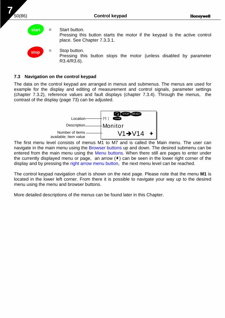
= Start button.Pressing this button starts the motor if the keypad is the active controlplace. See Chapter 7.3.3.1.
= Stop button.Pressing this button stops the motor (unless disabled by parameterR3.4/R3.6).
7.3 Navigation on the control keypad
The data on the control keypad are arranged in menus and submenus. The menus are used forexample for the display and editing of measurement and control signals, parameter settings(chapter 7.3.2), reference values and fault displays (chapter 7.3.4). Through the menus, thecontrast of the display (page 73) can be adjusted.
The first menu level consists of menus M1 to M7 and is called the Main menu. The user cannavigate in the main menu using the Browser buttons up and down. The desired submenu can beentered from the main menu using the Menu buttons. When there still are pages to enter underthe currently displayed menu or page, an arrow ( ) can be seen in the lower right corner of thedisplay and by pressing the right arrow menu button, the next menu level can be reached.
The control keypad navigation chart is shown on the next page. Please note that the menu M1 islocated in the lower left corner. From there it is possible to navigate your way up to the desiredmenu using the menu and browser buttons.
More detailed descriptions of the menus can be found later in this Chapter.
start
stop
MonitorV1"V14
STOP READY
LocalLocation
Description
Number of itemsavailable; Item value

Control keypad 51(86)7
Figure 7-3. Keypad navigation chart
F T1 "T7
STOP FAULT
I/Oterm
STOP
I/Oterm
FAULT
H1"H3
READY
I/Oterm
T1"T7
I/Ote rm
READY
I/Oterm
READY
S1"S9
STOP READY
I/Oterm
STOP READY
I/Otermenter
G1"G5
READY
I/Oterm
A:NXOPTC1
READY
I/Oterm
G1"G1
READY
I/Oterm
F0
STOP FAULT
I/Oterm
OR: 11 Output phase Operation days17
Fault history 11 Output phase Operation days
System Menu ApplicationChangevalue
Browse
Expander boards ParametersP1"P3
Active faults
17
Standard
V1"V15
READY
I/Oterm
RUN
13.95 Hz
READY
I/Oterm
RUN
G1"G9
READY
I/Oterm
P1"P15
READY
I/Oterm
13.95 Hz
READY
Loc al
P1"P3
READY
I/Ote rm
STOP READY
I/Ote rm
STOP
enter
enter
Parameters Basic parameters Min Frequency
Monitor Output frequency No editing!
Keypad control Control PlaceI/O Terminal
Changevalue
Changevalue
Browse
Browse

52(86) Control keypad7
7.3.1 Monitoring menu (M1)
The monitoring menu can be entered from the main menu by pushing the Right arrow menubutton when the location indication M1 is visible on the first line of the display. How to browsethrough the monitored values is presented in Figure 7-4.The monitored signals carry the indication V#.# and they are listed in Table 7-1. The values areupdated once every 0.3 seconds.
This menu is only for signal checking. The values cannot be altered here. For changing values ofparameters see Chapter 7.3.2.
Figure 7-4. Monitoring menu
Code Signal name Unit Description
V1.1 Output frequency Hz Frequency to the motor
V1.2 Frequency reference Hz
V1.3 Motor speed rpm Calculated motor speed
V1.4 Motor current A Measured motor current
V1.5 Motor torque % Calculated actual torque/nominal torque of the unit
V1.6 Motor power % Calculated actual power/nominal power of the unit
V1.7 Motor voltage V Calculated motor voltage
V1.8 DC-link voltage V Measured DC-link voltage
V1.9 Unit temperature ºC Heat sink temperature
V1.10 Voltage input V AI1
V1.11 Current input mA AI2
V1.12 DIN1, DIN2, DIN3 Digital input statuses
V1.13 DIN4, DIN5, DIN6 Digital input statuses
V1.14 DO1, RO1, RO2 Digital and relay output statuses
V1.15 Analogue output current mA AO1
Table 7-1. Monitored signals
Note: Other applications may embody more monitoring values.
MonitorV1"V14
READY
Local
Output frequency13.95 Hz
READY
Local
FreqReference13.95 Hz
R EADY
Local

Control keypad 53(86)7
7.3.2 Parameter menu (M2)
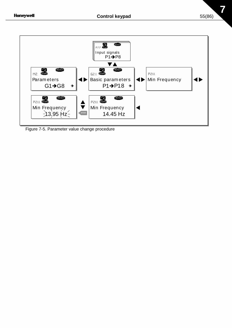
Parameters are the way of conveying the commands of the user to the frequency converter. Theparameter values can be edited by entering the Parameter Menu from the Main Menu when thelocation indication M2 is visible on the first line of the display. The value editing procedure ispresented in Figure 7-5.
Push the right arrow menu button once to move into the Parameter Group Menu (G#). Locate theparameter group desired by using the Browser buttons and push the HYPERLINK \l"menubuttonright" right arrow menu buttonagain to enter the group and its parameters. Use theBrowser buttons to find the parameter (P#) to edit. From here it is possible to, proceed in twodifferent ways: Pushing the right arrow menu button goes to the edit mode. As a sign of this, theparameter value starts to blink. The value can now be changed in two different ways.:
1 Just set the new desired value with the Browser buttons and confirm the change with theEnter button. Consequently, the blinking stops and the new value is visible in the value field.
2 Push the right arrow menu button once again. Now it is possible to be able to edit the valuedigit by digit. This editing manner may come in handy, when a relatively greater or smallervalue than that on the display is desired. Confirm the change with the Enter button.
The value will not change unless the Enter button is pushed. Pressing the left arrow menubutton returns to the previous menu.
Several parameters are locked, i.e. uneditable, when the drive is in RUN status. If an attempt ismade to edit the value of such a parameter the text *Locked* will appear on the display. Thefrequency converter must be stopped in order to edit these parameters.The parameters values can also be locked using the function in menu M6 (see Chapter

54(86) Control keypad7
Parameter lock (P6.3.2)).
Return to the Main menu anytime by pressing the left arrow menu button for 1—2 seconds.
The basic application package includes seven applications with different sets of parameters. Theparameter lists are in the Application Section of this manual.
Once in the last parameter of a parameter group, To move directly to the first parameter of thatgroup press the Browser button up.
See the diagram for parameter value change procedure on page 55.
Note: Instead of connecting power to the frequency converter, it is possible to power up thecontrol board from an external power source by connecting the external power source tobidirectional terminal #6 of the NXOPTA1 board (see page 43) or to the corresponding +24Vterminal on any other option board. This voltage is high enough to set parameter values or tokeep the fieldbus active.
Control keypad 55(86)7
Figure 7-5. Parameter value change procedure
G1"G8
READY
Keypad
P1"P18
READY
Keypad
P1"P8
READY
Keypad
READY
Keypad
13.95 Hz enter
READY
Keypad
14.45 Hz
Parameters Basic parameters Min Frequency
Input signals
Min Frequency Min Frequency

56(86) Control keypad7
7.3.3 Keypad control menu (M3)
In the Keypad Controls Menu, it is possible to choose the control place, edit the frequencyreference and change the direction of the motor. Enter the submenu level with the right arrowmenu button.
7.3.3.1 Selection of control place
There are three different places (sources) which the frequency converter can be controlled from.For each control place, a different symbol will appear on the alphanumeric display:
Control place Symbol
I/O terminals
Keypad (panel)
Fieldbus
Change the control place by entering the edit mode with the right arrow menu button. The optionscan then be browsed through with the Browser buttons. Select the desired control place with theEnter button. See the diagram on the next page.See also 7.3.3 above.
NOTE! There are some special functions that can be performed when in the M3menu:
Select the keypad as the active control place by keeping the start
buttonpushed down for 3 seconds when the motor is running. The keypad will becomethe active control place and the current frequency reference and direction will becopied to the keypad.
Select the keypad as the active control place by keeping the stop
buttonpushed down for 3 seconds when the motor is stopped. The keypad will becomethe active control place and the current frequency reference and direction will becopied to the keypad.
Copy the frequency reference set elsewhere (I/O, fieldbus) to the panel by
keeping the enter
button pushed down for 3 seconds.
Note that Whilst in any other than M3 menu these functions will not work.If in a different menu other than M3 menu and try to start the motor by pressing the START buttonwhen the keypad is not selected as the active control place an error message Keypad Control NOTACTIVE will be displayed.
I/O term
Keypad
Bus/Comm

Control keypad 57(86)7
Figure 7-6. Selection of control place
7.3.3.2 Keypad reference
The keypad reference submenu (P3.2) displays and allows the operator to edit the frequencyreference. The changes will take place immediately. This reference value will not, however,influence the rotation speed of the motor unless the keypad has been selected as theactive control place.NOTE: The maximum difference between the output frequency and the keypad reference is 6 Hz.The application software monitors the keypad frequency automatically.See also 7.3.3 above.
See Figure 7-5 for how to edit the reference value (pressing the Enter button is not, however,necessary).
7.3.3.3 Keypad direction
The keypad direction submenu displays and allows the operator to change the rotating direction ofthe motor. This setting will not, however, influence the rotation direction of the motorunless the keypad has been selected as the active control place.See also 7.3.3 above
See Figure 7-6 for how to change the rotation direction.
Keypad controlP1"P3
READY
I/Oterm
Control PlaceI/O Remote
READY
I/Oterm
Control PlaceI/O Remote
I/Oterm
Control PlaceKeypad
READY
I/Oterm
enter Control PlaceKeypad
READY
Keypad
STOP STOP STOP
STOPSTOP
Note: Information on controlling the motor with the keypad is given in Chapters 7.2.1,7.3.3 and 8.2.

58(86) Control keypad7
7.3.4 Active faults menu (M4)
The Active faults menu can be entered from the Main menu by pushing the right arrow menubutton when the location indication M4 is visible on the first line of the keypad display.
When a fault brings the frequency converter to a stop, the location indication F1, the fault code, ashort description of the fault and the fault type symbol (see Chapter 7.3.4.1) will appear on thedisplay. In addition, the indication FAULT or ALARM (see Figure 7-1 or Chapter 7.1.1) is displayedand, in case of a FAULT, the red led on the keypad starts to blink. If several faults occursimultaneously, the list of active faults can be browsed with the Browser buttons.
The memory of active faults can store the maximum of 10 faults in the order of appearance. Thedisplay can be cleared with the Reset button and the read-out will return to the same state it wasbefore the fault trip. The fault remains active until it is cleared with the Reset button or with a resetsignal from the I/O terminal.
Note! Remove external Start signal before resetting the fault to prevent unintentional restart of thedrive.
Normal state,no faults:
7.3.4.1 Fault types
In the NX frequency converter, there are four different types of faults. These types differ from eachother on the basis of the subsequent behaviour of the drive. See Table 7-2.
Figure 7-7. Fault display
Active faultsF0
READY
I/Oterm
F T1 "T13
STOP FAULT
I/Oterm
STOP
I/Oterm
FAULT
34:21:05
STOP
I/Oterm
FAULT
17 11 Output phase Operations days
Operation hours
Faulttypesymbol

Control keypad 59(86)7
Fault type symbol MeaningA
(Alarm)This type of fault is a sign of an unusual operatingcondition. It does not cause the drive to stop, nor does itrequire any special actions. The 'A fault' remains in thedisplay for about 30 seconds.
F(Fault)
An 'F fault' is a kind of fault that makes the drive stop.Actions need to be taken in order to restart the drive.
AR(Fault Autoreset)
If an 'AR fault' occurs the drive will also stop immediately.The fault is reset automatically and the drive tries torestart the motor. Finally, if the restart is not successful, afault trip (FT, see below) occurs.
FT(Fault Trip)
If the drive is unable to restart the motor after an AR faultan FT fault occurs. The effect of the 'FT fault' is basicallythe same as that of the F fault: the drive is stopped.
Table 7-2. Fault types
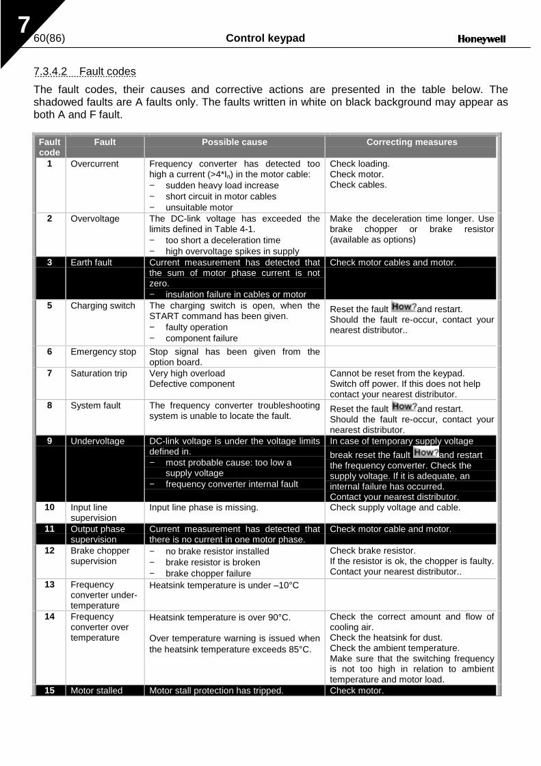
60(86) Control keypad7
7.3.4.2 Fault codes
The fault codes, their causes and corrective actions are presented in the table below. Theshadowed faults are A faults only. The faults written in white on black background may appear asboth A and F fault.
Faultcode
Fault Possible cause Correcting measures
1 Overcurrent Frequency converter has detected toohigh a current (>4*In) in the motor cable:− sudden heavy load increase− short circuit in motor cables− unsuitable motor
Check loading.Check motor.Check cables.
2 Overvoltage The DC-link voltage has exceeded thelimits defined in Table 4-1.− too short a deceleration time− high overvoltage spikes in supply
Make the deceleration time longer. Usebrake chopper or brake resistor(available as options)
3 Earth fault Current measurement has detected thatthe sum of motor phase current is notzero.− insulation failure in cables or motor
Check motor cables and motor.
5 Charging switch The charging switch is open, when theSTART command has been given.− faulty operation− component failure
Reset the fault and restart.Should the fault re-occur, contact yournearest distributor..
6 Emergency stop Stop signal has been given from theoption board.
7 Saturation trip Very high overloadDefective component
Cannot be reset from the keypad.Switch off power. If this does not helpcontact your nearest distributor.
8 System fault The frequency converter troubleshootingsystem is unable to locate the fault.
Reset the fault and restart.Should the fault re-occur, contact yournearest distributor.
9 Undervoltage DC-link voltage is under the voltage limitsdefined in.− most probable cause: too low a
supply voltage− frequency converter internal fault
In case of temporary supply voltage
break reset the fault and restartthe frequency converter. Check thesupply voltage. If it is adequate, aninternal failure has occurred.Contact your nearest distributor.
10 Input linesupervision
Input line phase is missing. Check supply voltage and cable.
11 Output phasesupervision
Current measurement has detected thatthere is no current in one motor phase.
Check motor cable and motor.
12 Brake choppersupervision
− no brake resistor installed− brake resistor is broken− brake chopper failure
Check brake resistor.If the resistor is ok, the chopper is faulty.Contact your nearest distributor..
13 Frequencyconverter under-temperature
Heatsink temperature is under –10°C
14 Frequencyconverter overtemperature
Heatsink temperature is over 90°C.
Over temperature warning is issued whenthe heatsink temperature exceeds 85°C.
Check the correct amount and flow ofcooling air.Check the heatsink for dust.Check the ambient temperature.Make sure that the switching frequencyis not too high in relation to ambienttemperature and motor load.
15 Motor stalled Motor stall protection has tripped. Check motor.

Control keypad 61(86)7
Faultcode
Fault Possible cause Correcting measures
16 Motorovertemperature
Motor overheating has been detected byfrequency converter motor temperaturemodel. Motor is overloaded.
Decrease the motor load.If no motor overload exists, check thetemperature model parameters.
17 Motor underload Motor underload protection has tripped.2223
EEPROMchecksum fault
Parameter save fault− faulty operation− component failure
24 Changed datawarning
Changes may have occurred in thedifferent counter data due to mainsinterruption
No special actions required. Take acritical attitude to the counter data.
25 Microprocessorwatchdog fault
− faulty operation− component failure
Reset the fault and restart.Should the fault re-occur, contact yournearest distributor..
32 Fan cooling Cooling fan of the frequency converterdoes not start, when ON command isgiven
Contact your nearest distributor..
34 CAN buscommunication
Sent message not acknowledged. Ensure that there is another device onthe bus with the same configuration.
36 Control unit NXS Control Unit can not control NXPPower Unit and vice versa
Change control units
37 Device change Option board changed.Different power rating of drive.
Reset
38 Device added Option board added.Drive of different power rating added.
Reset
39 Device removed Option board removed.Drive removed.
Reset
40 Device unknown Unknown option board or drive.41 IGBT temperature IGBT Inverter Bridge overtemperature
protection has detected too high a shortterm overload current
Check loading.Check motor size.
42 Brake resistorovertemperature
Brake resistor overtemperature protectionhas detected too heavy braking
Set the deceleration time longer.Use external brake resistor.
43 Encoder fault Note the exceptional Fault data record.See 7.3.4.3. Additional codes:1 = Encoder 1 channel A is missing2 = Encoder 1 channel B is missing3 = Both encoder 1 channels are missing4 = Encoder reversed
Check encoder channel connections.Check the encoder board.
50 Analogue inputIin < 4mA(selected signalrange 4 to 20mA)
Current at the analogue input is < 4mA.− control cable is broken or loose− signal source has failed
Check the current loop circuitry.
51 External fault Digital input fault.52 Keypad
communicationfault
The connection between the controlkeypad and the frequency converter isbroken.
Check keypad connection and possiblekeypad cable.
Table 7-3. Fault codes

62(86) Control keypad7
7.3.4.3 Fault time data record
When a fault occurs the information described above in 7.3.4 is displayed. By pushing the rightarrow menu button it is possible to view the Fault time data record menu indicated by T.1####T.13.In this menu, some selected important data valid at the time of the fault are recorded. This featureis intended to help the user or the service person to determine the cause of fault.
The data available are:
T.1 Counted operation days(Fault 43: Additional code)
d
T.2 Counted operation hours(Fault 43: Counted operation days)
hh:mm:ss(d)
T.3 Output frequency(Fault 43: Counted operation hours)
Hz(hh:mm:ss)
T.1 Counted operation days dT.2 Counted operation hours hh:mm:ssT.3 Output frequency HzT.4 Motor current AT.5 Motor voltage VT.6 Motor power %T.7 Motor torque %T.8 DC voltage VT.9 Unit temperature °CT.10 Run statusT.11 DirectionT.12 WarningsT.13 0-speed
Table 7-4. Fault time recorded data

Control keypad 63(86)7
7.3.5 Fault history menu (M5)
The Fault history menu can be entered from the Main menu by pushing the right arrow menubutton Menu button right when the location indication M5 is visible on the first line of the keypaddisplay.
All faults are stored in the Fault history menu, Browse through them using the Browser buttons.Additionally, the Fault time data record pages (see Chapter 7.3.4.3) are accessible at each fault.Return to the previous menu anytime by pushing the Menu button left.
The memory of the frequency converter can store a maximum of 30 faults in the order ofappearance. The number of faults currently in the fault history is shown on the value line of themain page (H1####H#). The order of the faults is indicated by the location indication in the upper leftcorner of the display. The latest fault carries the indication F5.1, the second latest F5.2 etc. Ifthere are 30 uncleared faults in the memory the next occurring fault will erase the oldest from thememory.
Pressing the Enter button for about 2 to 3 seconds resets the whole fault history. Then, the symbolH# will change to 0.
Figure 7-8. Fault history menu
H1"H3
READY
I/Oterm
T1"T7
I/Oterm
READY
I/Oterm
READY
I/Oterm
I/Oter m
enter
17Fault history 11 Output phase
5 ChargeSwitch
Operation days
Operation hours
PUSH to reset

64(86) Control keypad7
7.3.6 System menu (M6)
The System menu can be entered from the main menu by pushing the right arrow menu buttonMenu button right when the location indication M6 is visible on the display.
The controls associated with the general use of the frequency converter, such as applicationselection, customised parameter sets or information about the hardware and software are locatedunder the System menu. The number of submenus and sub pages is shown with the symbol S (orP) on the value line.
On page 65 is a list of the functions available in the System menu.
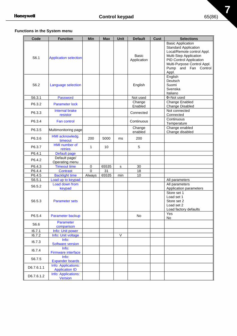
Control keypad 65(86)7
Functions in the System menu
Code Function Min Max Unit Default Cust Selections
S6.1 Application selection BasicApplication
Basic ApplicationStandard ApplicationLocal/Remote control Appl.Multi-Step ApplicationPID Control ApplicationMulti-Purpose Control Appl.Pump and Fan ControlAppl.
S6.2 Language selection English
EnglishDeutschSuomiSvenskaItaliano
S6.3.1 Password Not used 0=Not used
P6.3.2 Parameter lock ChangeEnabled
Change EnabledChange Disabled
P6.3.3 Internal brakeresistor Connected Not connected
Connected
P6.3.4 Fan control Continuous ContinuousTemperature
P6.3.5 Multimonitoring page Changeenabled
Change enabledChange disabled
P6.3.6 HMI acknowledg.timeout
200 5000 ms 200
P6.3.7 HMI number ofretries 1 10 5
P6.4.1 Default page
P6.4.2 Default page/Operating menu
P6.4.3 Timeout time 0 65535 s 30P6.4.4 Contrast 0 31 18P6.4.5 Backlight time Always 65535 min 10S6.5.1 Load up to keypad All parameters
S6.5.2 Load down fromkeypad
All parametersApplication parameters
S6.5.3 Parameter sets
Store set 1Load set 1Store set 2Load set 2Load factory defaults
P6.5.4 Parameter backup No YesNo
S6.6 Parametercomparison
I6.7.1 Info: Unit powerI6.7.2 Info: Unit voltage V
I6.7.3 Info:Software version
I6.7.4 Info:Firmware interface
S6.7.5 Info:Expander boards
D6.7.6.1.1 Info: Applications:Application ID
D6.7.6.1.2 Info: Applications:Version

66(86) Control keypad7
Code Function Min Max Unit Default Cust Selections
D6.7.6.1.3 Info: Applications:Firmware interface
C6.8.1 MWh counter kWh
C6.8.2 Operating dayscounter
C6.8.3 Operating hourscounter hh:mm:ss
T6.9.1 MWh trip counter kWh
T6.9.2 ClearMWh trip counter
T6.9.3 Operating daystrip counter
T6.9.4 Operating hourstrip counter
hh:mm:ss
T6.9.5 Clear operating timecounter
Table 7-5. System menu functions

Control keypad 67(86)7
7.3.6.1 Application selection
The user can select the application desired by entering the Application selection page (S6.1). Thisis done by pushing the right arrow menu button when on the first page of the System menu.Change the application by pushing the right arrow menu button once again. The name of theapplication starts to blink. Browse through the applications with the Browser buttons and selectanother application with the Enter button.
In this phase, the display requests whether theparameters of the new application are to beuploaded to the keypad. If so press the Enter button Pushing any other button leaves theparameters of the previously used application saved in the keypad. For more information, seeChapter 7.3.6.5.
For more information about the Application Package, see the NX Application Manual.
Figure 7-9. Change of application
7.3.6.2 Language selection
The HMI control keypad offers the user the possibility to control the frequency converter throughthe keypad in the language of your choice.
Locate the language selection page under the System menu. Its location indication is S6.2. Pressthe right arrow menu button once to enter the edit mode. As the name of the language starts toblink choose another language for the keypad texts. Confirm the selection by pushing the Enterbutton The blinking stops and all textual information on the keypad is presented in the languagechosen.
Return to the previous menu anytime by pushing the left arrow menu button.
System MenuS1"S11
STOP READY
I/Oterm
ApplicationStandard
STOP READY
I/Oterm
ApplicationStandard
STOP READY
I/Oterm
enter ApplicationMulti-step
STOP READY
I/Oterm

68(86) Control keypad7
Figure 7-10. Selection of language
7.3.6.3 System settings
In the System settings submenu (S6.3) under the System menu it is possible to further customisethe frequency converter operator interface. The functions available in this menu are Password,Parameter lock, Internal brake resistor connection, Fan control, HMI acknowledge timeoutand HMI retry.
Password (S6.3.1)
The application selection can be protected against unauthorised changes with the Passwordfunction (S6.3.1).By default, the password function is not in use. To activate the function, enter the edit mode bypushing the right arrow menu button. A blinking zero appears in the display and a password canbe set with the Browser buttons. The password can be any number between 1 and 65535.
Note The password can be set by digits. In the edit mode, push the right arrow menu button onceagain and another zero appears on the display. First set the units. Push the left arrow menubutton and set the tens etc. Finally, confirm the password setting with the Enter button. After this,wait until the Timeout time (P6.4.3) (see page 72) has expired before the password function isactivated.If the applications or the password itself are changed the system will request the currentpassword. The password will be entered with the Browser buttons.
Figure 7-11. Password setting
Note! Store the password in a secure location! No changes can be made unless a valid passwordis entered!
READY
I/Oterm
0
READY
I/Oterm
OR:
enter
00
READY
I/Oterm enter
PasswordNot in use
Password Password
System MenuS1"S11
READY
I/Oterm
LanguageEnglish
READY
I/Oterm
LanguageEnglish
READY
I/Oterm
enter LanguageSuomi
READY
I/Oterm

Control keypad 69(86)7
Parameter lock (P6.3.2)
This function allows the user to prohibit changes to the parameters.
If the parameter lock is activated the text *locked* will appear on the display when the parametervalue is edited.
NOTE: This function does not prevent unauthorised editing of parameter values.
Enter the edit mode by pushing the right arrow menu button HYPERLINK \l "menubuttonright".Use the Browser buttons to change the parameter lock status. Accept the change with the Enterbutton or return to the previous level with the left arrow menu button Menu button left.
Figure 7-12. Parameter locking
Internal brake resistor connection (P6.3.3)
With this function it is possible to tell the frequency converter, whether the internal brake resistor isconnected or not. If the frequency converter has been ordered with an internal brake resistor, thedefault value of this parameter is Connected. However, if it is necessary to increase brakingcapacity by installing an external brake resistor, or if the internal brake resistor is disconnected foranother reason, it is advisable to change the value of this function to Not conn. in order to avoidunnecessary fault trips.
Enter the edit mode by pushing the right arrow menu button . Use the Browser buttons to changethe internal brake resistor status. Accept the change with the Enter button or return to the previouslevel with the left arrow menu button.
Note! The brake resistor is available as optional equipment for all classes. It can be installedinternally in classes FR4 – FR6.
S1"S9
READY
I/Oterm
READY
I/Oterm
READY
I/Oterm
enter
READY
I/Oterm
READY
I/Oterm
P1"P7System Menu System settings
Parameter Lock
ChangeEnable
Parameter LockChangeDisabl
Parameter Lock
ChangeEnable

70(86) Control keypad7
Figure 7-13. Internal brake resistor connection
Fan control (P6.3.4)
This function allows the control of the frequency converter’s cooling fan. When the power isswitched on the fan can be set to run continuously or dependant on the temperature of the unit. Ifthe latter function has been selected the fan is switched on automatically when the heat sinktemperature reaches 60°C. The fan receives a stop command when the heat sink temperaturefalls to 55°C. However the fan runs for about a minute after receiving the stop command, as wellas after changing the value from Continuous to Temperature.
Enter the edit mode by pushing the right arrow menu button. The present mode shown starts toblink. Use the Browser buttons to change the fan mode. Accept the change with the Enter buttonor return to the previous level with the left arrow menu button.
Figure 7-14. Fan control function
HMI acknowledge timeout (P6.3.6)
This function allows the user to change the timeout of the HMI acknowledgement time.
Note! If the frequency converter has been connected to the PC with a normal cable, the defaultvalues of parametres 6.3.6 and 6.3.7 (200 and 5) must not be changed.If the frequency converter has been connected to the PC via a modem and there is a delay intransferring messages, the value of par. 6.3.6 must be set according to the delay as follows:
S1"S9
READY
I/Oterm
READY
I/Oterm
READY
I/Oterm
enter
READY
I/Oterm
I/Oterm
P1"P7System Menu System settings
InternBrakeRes
Connected
Not conn.
InternBrakeRes
ConnectedInternBrakeRes
READY
I/Oterm
READY
I/Oterm
enter
READY
I/Oterm
Fan controlContinuous
Fan control Fan controlContinuous Temperature
OR:

Control keypad 71(86)7
Example:• Transfer delay between the frequency converter and the PC = 600 ms• The value of par. 6.3.6 is set to 1200 ms (2 x 600, sending delay + receiving
delay)• The corresponding setting shall be entered to the [Misc]-part of the
NCDrive.ini – file:Retries = 5AckTimeOut = 1200TimeOut = 6000
It must also be considered that intervals that are shorter than the AckTimeOut-time cannot beused in NCDrive monitoring.
Enter the edit mode by pushing the right arrow menu button. Use the Browser buttons to changethe acknowledgement time. Accept the change with the Enter button or return to the previous levelwith the left arrow menu button .
Figure 7-15. HMI acknowledge timeout
Number of retries to receive HMI acknowledgement (P6.3.7)
With this parameter it is possible to set the number of times the drive will try to receiveacknowledgement if this does not happen within the acknowledgement time (P6.3.6) or if thereceived acknowledgement is faulty.
Enter the edit mode by pushing the right arrow menu button. The present value shown starts toblink. Use the Browser buttons to change the amount of retries. Accept the change with the Enterbutton or return to the previous level with the left arrow menu button
See Figure 7-15 for the procedure of changing the value.
7.3.6.4 Keypad settings
Further customisation of the freqency converter operator interface can be undertaken in theKeypad settings submenu under the System menu.Locate the Keypad settings submenu (S6.4). Under the submenu, there are four pages (P#)associated with the keypad operation:
READY
I/Oterm
200ms
READY
I/Oterm
enter
200msHMI ACK timeout HMI ACK timeout

72(86) Control keypad7
Figure 7-16. Keypad settings submenu
Default page (P6.4.1)
This menu allows the user to set the location (page) to which the display automatically moves as theTimeout time (see below) has expired or as the power is switched on to the keypad.
If the Default Page value is 0 the function is not activated, i.e. the last displayed page remains on thekeypad display. Press the right arrow menu button once to enter the edit mode. Change the number of theMain menu with the Browser buttons. Pressing the right arrow menu button once again enables editing ofthe number of the submenu/page. If the page to move to by default is at the third level repeat theprocedure. Confirm the new default page value with the Enter button. Return to the previous step anytimeby pushing the left arrow menu button.
Figure 7-17. Default page function
Default page in the operating menu (P6.4.2)
To set the location (page) in the Operating menu (in special applications only) to which the displayautomatically moves as the set Timeout time (see below) has expired or as the power is switched on to thekeypad. See setting of Default page above.
Timeout time (P6.4.3)
The Timeout time setting defines the time after which the keypad display returns to the Default page(P6.4.1) see above.Move to the Edit menu by pressing the right arrow menu button. Set the timeout time required and confirmthe change with the Enter button. Return to the previous step anytime by pushing the left arrow menubutton.
Figure 7-18. Timeout time setting
Note: If the Default page value is 0 the Timeout time setting has no effect.
P1"P5
READY
I/Oterm
0.
READY
I/Oterm
Keypad settings Default page
0.
READY
I/Oterm
READY
I/Oterm
READY
I/Oterm
0. 1.
enter
Default page Default page Default page REPEAT TO SETDEFAULT SUBMENU/PAGE
CANCEL
CONFIRM CHANGE
90 s
READY READY
I/Oterm
READY
I/Oterm
90 s.
enterI/Oterm
60 s.Timeout time Timeout time Timeout time
CANCEL
CONFIRM CHANGE
Control keypad 73(86)7
Contrast adjustment (P6.4.4)
In case the display is unclear adjust the contrast through the same procedure as that for thetimeout time setting (see above).
Backlight time (P6.4.5)
Giving a value for the Backlight time, can determine how long the backlight stays on before goingout. Select here any time between 1 and 65535 minutes or 'Forever'. For the value settingprocedure see Timeout time (P6.4.3).
7.3.6.5 Parameter copy
The parameter copy function is used when the operator wants to copy one or all parameter groupsfrom one drive to another. All the parameter groups are first uploaded to the keypad, then thekeypad is connected to another drive and then the parameter groups are downloaded to it (orpossibly back to the same drive).
Before any parameters can successfully be copied from one drive to another the drive has to bestopped when the parameters are downloaded to it:
The parameter copy menu (S6.5) embodies two functions:
Upload parameters to keypad (To keypad, S6.5.1)
This function uploads all existing parameter groups to the keypad provided that the drive isstopped.
Enter the To keypad page (S6.5.1) from the Parameter copy menu. Push the right arrow menubutton to enter the edit mode. Use the Browser buttons to select the option All parameters andpress the Enter button. Wait until 'OK' appears on the display.
Figure 7-19. Parameter copy to keypad
P1"P4
READY
I/Oterm
READY
I/Oterm
READY
I/Oterm enter
READY
I/Oterm
READY
I/Oterm
Copy Parameters Up to keypad Up to keypadSelect CANCEL
CONFIRM
Up to keypadWait...
Up to keypadOK
All param.

74(86) Control keypad7
Download parameters to drive (From keypad, S6.5.2)
This function downloads one or all parameter groups uploaded to the keypad to a drive providedthat the drive is in STOP status.
Enter the From keypad page (S6.5.2) from the Parameter copy menu. Push the right arrow menubutton to enter the edit mode. Use the Browser buttons to select either the option All parametersor Application parameters and press the Enter button. Wait until 'OK' appears on the display.
The procedure to download the parameters from keypad to drive is similar to that of from drive tokeypad. See above.
Parameter sets (S6.5.3)
The NX frequency converter features a possibility for the user to store and load two customisedparameter sets (all parameters included in the application) and to load back the factory defaultparameter values.
On Parameter sets page (S6.7), push the right arrow menu button to enter the Edit menu. The textSelect begins to blink allowing you to choose any of the storing or loading functions with theBrowser buttons. You can store or load two customised parameter sets or load back the factorydefaults. Confirm with the Enter button. Wait until 'OK' appears on the display.
Figure 7-20. Storing and loading of parameter sets
Parameter backup (P6.5.4)
On this page the user can activate or inactivate the parameter backup function. Enter the editmode by pressing the right arrow menu button. Choose Yes or No with the Browser buttons.
When the Parameter backup function is activated the NX control keypad makes a copy of theparameters of the presently used application. When applications are changed, the user will beasked if they wish the parameters of the new application to be uploaded to the keypad. For this tohappen, push the Enter button. If a copy is required of the parameters of the previously usedapplication saved in the keypad push any other button. The user will be able to download theseparameters to the drive following the instructions given in chapter 7.3.6.5.
READY
I/Oterm
READY
I/Otermenter
READY
I/Oterm
READY
I/Oterm
OK
Parameter setsSelect
Parameter setsCANCEL
CONFIRM
Parameter setsWait...
Parameter sets
Store Set1

Control keypad 75(86)7
If the user wants the parameters of the new application to be automatically uploaded to thekeypad this will have to be done for the parameters of the new application once on page 6.5.1 asinstructed. Otherwise the panel will always ask for the permission to upload the parameters.
Note: Parameters saved in the parameter settings on page S6.5.3 will be deleted whenapplications are changed If transfer of the parameters from one application to another is required,they must be uploaded first to the keypad.
7.3.6.6 Parameter comparison
In the Parameter comparison submenu (S6.6), the actual parameter values to the values ofthecustomised parameter sets and those loaded to the control keypad can be compared.
The comparison is performed by pushing the right arrow menu button when in the Parametercomparison submenu. The actual parameter values are first compared to those of the customisedparameter Set1. If no differences are detected a '0' is displayed on the lowermost line. But if anyof the parameter values differ from those of the Set1 the number of the deviations is displayedtogether with symbol P (e.g. P1#P5 = five deviating values). By pressing the right arrow menubutton once again it is possible to enter the pages where both the actual value and the value itwas compared to can be seen. In this display, the value on the Description line (in the middle) isthe default value and the one on the value line (lowermost) is the edited value. Furthermore, it ispossible to also edit the actual value with the Browser buttons in the edit mode that you can reachby pushing the right arrow menu button once again.
Figure 7-21. Parameter comparison
C1"C3
READY READY
I/Oterm
READY
I/Oterm
0
enter
I/Oterm
P1"P6P2.1.2= 50.0
READY
I/Oterm
20.0 Hz
P2.1.2= 50.0
READY
I/Oterm
20.0 Hz
ParamComparison Set1
Set1
CONFIRM CHANGE
EDIT VALUE
OR

76(86) Control keypad7
7.3.6.7 Information submenu
In the Information submenu (S6.7) frequency converter-related hardware and software informationas well as operation-related information, can be found.
Enter the Info menu by pressing the right arrow menu button. The user can now browse throughthe information pages with the Browser buttons.
Page Content6.7.1 Nominal power of the unit (constant torque)6.7.2 Nominal voltage of the unit6.7.3 Control board software version6.7.4 Application interface version of the software6.7.5 Expander board statuses and program versions6.7.6 Application-related software information6.7.7 Debug menu (for advanced users)
Table 7-6. Information pages
Expander board information (S6.7.5)
Information about the basic and option boards connected to the control board can be found in theExpanders submenu (see Chapter 6.2).
You can check the status of each slot by entering the board submenu with the right arrow menubutton and using the Browser buttons to choose the board whose status you wish to check. Pushthe right arrow menu button again to display the status of the board. The keypad will also displaythe program version of the respective board when either one of the Browser buttons is pushed.If no board is connected to the slot the text 'no board' will be shown. If a board is connected to aslot but the connection is somehow lost the text 'no conn.' is displayed. See Chapter 6.2 andFigure 6-12 and 6-11 for more information.
For more information on the expander board-related parameters, see Chapter 7.3.7.
Figure 7-22. Expander board information menus
E1"E7
READY
I/Oterm
A:NXOPTA1A
I/Oterm
READY
B:NXOPTA2
I/Oterm
READY
E1"E2State
I/Oterm
Run
I/Oterm
E1"E2Program version10001.0
Expanders

Control keypad 77(86)7
Applications info submenu (S6.7.6)
At location S6.7.6 is the Applications submenu containing information about not only theapplication currently in use but also all other applications loaded into the frequency converter. Theinformation available is:
1. Application identification number2. Application version number3. Firmware interface number
In the Application information submenu, push the right arrow menu button to enter the Applicationpages of which there are as many as there are applications loaded into the frequency converter.Locate the application you want information about with the Browser buttons and then enter theInformation pages with the right arrow menu button. Use again the Browser buttons to see thedifferent pages.
Figure 7-23. Applications info submenu
7.3.6.8 Counters menu
In the Counters menu (S6.8) is information related to the frequency converter operation times, i.e.the total numbers of MWh, operation days and operation hours passed so far. Unlike the countersin the Trip counters submenu, these counters cannot be reset.
Note! The operation time counter (days and hours) runs always, when the power is on.
Page CounterC6.8.1. MWh counterC6.8.2. Operation day counterC6.8.3. Operation hour counter
Table 7-7. Counter pages
A1 "A7
I/Oterm I/Oterm
D1"D3
I /Oterm
READY READY
READY
D1 "D3
I/Oterm
NXFIFF01
I/Oterm
Applications Basic
Standard
Application id
Version

78(86) Control keypad7
7.3.6.9 Trip counters submenu
Trip counters (menu S6.9) are counters the values of which can be reset i.e. restored to zero. Thefollowing resettable counters are available:
Note! The trip counters run only when the motor is running.
Page CounterT6.9.1. MWh counterT6.9.3. Operation day counterT6.9.4. Operation hour counter
Table 7-8. Resettable counters
The counters can be reset on pages 6.9.2. (MWh counter reset) and 6.9.5. (Operation time reset).
Example: To reset the operation counters::
Figure 7-24. Counter reset
T1"T5
READY
I/Oterm
READY
I/Oterm
READY
I/Oterm
enter
READY
I/Oterm
READY
I/Oterm
STOP STOP
STOP STOP
Trip counters Clr Optime cntr Clr Optime cntrNot reset Not reset
Clr Optime cntrReset
Clr Optime cntrReset

Control keypad 79(86)7
7.3.7 Expander board menu (M7)
The Expander board menu makes it possible for the user 1) to see what expander boards areconnected to the control board and 2) to reach and edit the parameters associated with theexpander board.Enter the following menu level (G#) with the right arrow menu button At this level, the user canbrowse through slots (see page 40) A to E with the Browser buttons to see what expander boardsare connected. The lowermost line of the display shows the number of parameters associated withthe board. It is possible to view and edit the parameter values in the same way as described inchapter 7.3.2. See Table 7-9 and Figure 7-25.
Expander board parameters
Code Parameter Min Max Default Cust Selections
P7.1.1.1 AI1 mode 1 5 3
1=0…20 mA2=4…20 mA3=0…10 V4=2…10 V5=–10…+10 V
P7.1.1.2 AI2 mode 1 5 1 See P7.1.1.1
P7.1.1.3 AO1 mode 1 4 1
1=0…20 mA2=4…20 mA3=0…10 V4=2…10 V
Table 7-9. Expander board parameters (board NXOPTA1)
Figure 7-25. Expander board information menu
G1"G5
READY
I/Oterm
C:NXOPTC1
READY
I/Oterm
G1"G2
READY
I/Oterm
READY
I/Oterm
enter
P1"P4
D:NXOPTC2
REA DY
I/Oterm
G1"G2
REA DY
I/Oterm
V1"V2
READY
I/Oterm
REA DY
I/Oterm
Expander boards Parameters
Slave address126
CHANGE VALUE
CONFIRM CHANGESlave address
126
Baud rate
Auto
Monitor

80(86) Control keypad7
7.4 Further keypad functions
The NX control keypad embodies additional application-related functions. See the NX ApplicationPackage for more information.

Commissioning 81(86)
8
8. COMMISSIONING
8.1 Safety
Before commissioning, note the following directions and warnings:
1 Internal components and circuit boards of the frequency converter(except for the galvanically isolated I/O terminals) are live when the NX isconnected to mains potential. Coming into contact with this voltage isextremely dangerous and may cause death or severe injury.
2 The motor terminals U, V, W and the DC-link/brake resistor terminals –/+are live when the NX is connected to mains, even if the motor is notrunning.
3 The control I/O-terminals are isolated from the mains potential. However,the relay outputs and other I/O-terminals may have a dangerous controlvoltage present even when the NX is disconnected from mains.
4 Do not make any connections with the frequency converter connected tothe mains.
5 After having disconnected the frequency converter from the mains, waituntil the fan stops and the indicators on the keypad go out (if no keypadis attached see the indicator through the keypad base). Wait 5 moreminutes before doing any work on the NX connections. Do not even openthe cover before this time has expired.
6 Before connecting the frequency converter to mains make sure that theNX front cover is closed.
8.2 Commissioning of the frequency converter
1 Read the safety instructions in Chapter 1 and above and follow them.
2 After the installation, pay attention to:
- that both the frequency converter and the motor are grounded.
- that the mains and motor cables comply with the requirements given in Chapter 6.1.1.
- that the control cables are located as far as possible from the power cables (seeChapter 6.1.2, step 3), the shields of the shielded cables are connected to protective
earth . The wires may not touch the electrical components of the frequencyconverter.
- that the common inputs of digital input groups are connected to +24V or ground of theI/O terminal or the external supply.
3 Check the quality and quantity of cooling air (Chapter 5.2, and Table 5-7).
4 Check the inside of the frequency converter for condensation.
5 Check that all Start/Stop switches connected to the I/O terminals are in Stop-position.
6 Connect the frequency converter to mains.
WARNING

82(86) Commissioning
8
7 Set the parameters of group 1 (See the Application Manual) according to therequirements of the application. At least the following parameters should be set:
- motor nominal voltage- motor nominal frequency- motor nominal speed- motor nominal current
The values needed for the parameters are on the motor rating plate.
8 Perform run test without motor
Perform either Test A or Test B:
A Controls from the I/O terminals:
a) Turn the Start/Stop switch to ON position.
b) Change the frequency reference (potentiometer)
c) Check in the Monitoring menu M1 that the value of Output frequency changesaccording to the change of frequency reference.
d) Turn the Start/Stop switch to OFF position.
B Control from the control keypad:
a) Change the control from the I/O terminals to the keypad as advised in Chapter7.3.3.1.
b) Push the Start button on the keypad start
.
c) Move over to the Keypad control menu (M3) and Keypad Reference submenu(Chapter 7.3.3.2) and change the frequency reference using the Browser buttons
+-
.
d) Check in the Monitoring menu M1 that the value of Output frequency changesaccording to the change of frequency reference.
e) Push the Stop button on the keypad stop
.
9 Run the start-up tests without the motor being connected to the process, if possible. Ifthis is not possible, secure the safety of each test prior to running it. Inform co-workers ofthe tests.
a) Switch off the supply voltage and wait up until the drive has stopped as advised atChapter 8.1, step 5.
b) Connect the motor cable to the motor and to the motor cable terminals of thefrequency converter.
c) Ensure that all Start/Stop switches are in Stop positions.
d) Switch the mains ON
e) Repeat test 8A or 8B.

Commissioning 83(86)
8
10 Connect the motor to the process (if the startup test was run without the motor beingconnected)
a) Before running the tests, make sure that this can be done safely.
b) Inform co-workers of the tests.
c) Repeat test 8A or 8B.
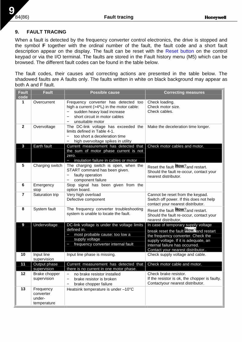
84(86) Fault tracing9
9. FAULT TRACING
When a fault is detected by the frequency converter control electronics, the drive is stopped andthe symbol F together with the ordinal number of the fault, the fault code and a short faultdescription appear on the display. The fault can be reset with the Reset button on the controlkeypad or via the I/O terminal. The faults are stored in the Fault history menu (M5) which can bebrowsed. The different fault codes can be found in the table below.
The fault codes, their causes and correcting actions are presented in the table below. Theshadowed faults are A faults only. The faults written in white on black background may appear asboth A and F fault.
Faultcode
Fault Possible cause Correcting measures
1 Overcurrent Frequency converter has detected toohigh a current (>4*In) in the motor cable:− sudden heavy load increase− short circuit in motor cables− unsuitable motor
Check loading.Check motor size.Check cables.
2 Overvoltage The DC-link voltage has exceeded thelimits defined in Table 4-1.− too short a deceleration time− high overvoltage spikes in utility
Make the deceleration time longer.
3 Earth fault Current measurement has detected thatthe sum of motor phase current is notzero.− insulation failure in cables or motor
Check motor cables and motor.
5 Charging switch The charging switch is open, when theSTART command has been given.− faulty operation− component failure
Reset the fault and restart.Should the fault re-occur, contact yournearest distributor.
6 Emergencystop
Stop signal has been given from theoption board.
7 Saturation trip Very high overloadDefective component
Cannot be reset from the keypad.Switch off power. If this does not helpcontact your nearest distributor.
8 System fault The frequency converter troubleshootingsystem is unable to locate the fault.
Reset the fault and restart.Should the fault re-occur, contact yournearest distributor,
9 Undervoltage DC-link voltage is under the voltage limitsdefined in.− most probable cause: too low a
supply voltage− frequency converter internal fault
In case of temporary supply voltage
break reset the fault and restartthe frequency converter. Check thesupply voltage. If it is adequate, aninternal failure has occurred.Contact your nearest distributor..
10 Input linesupervision
Input line phase is missing. Check supply voltage and cable.
11 Output phasesupervision
Current measurement has detected thatthere is no current in one motor phase.
Check motor cable and motor.
12 Brake choppersupervision
− no brake resistor installed− brake resistor is broken− brake chopper failure
Check brake resistor.If the resistor is ok, the chopper is faulty.Contactyour nearest distributor.
13 Frequencyconverterunder-temperature
Heatsink temperature is under –10°C

Fault tracing 85(86)9
14 Frequencyconverter overtemperature
Heatsink temperature is over 90°C.
Over temperature warning is issued whenthe heatsink temperature exceeds 85°C.
Check the correct amount and flow ofcooling air.Check the heatsink for dust.Check the ambient temperature.Make sure that the switching frequencyis not too high in relation to ambienttemperature and motor load.
15 Motor stalled Motor stall protection has tripped. Check motor.16 Motor
overtemperatureMotor overheating has been detected byfrequency converter motor temperaturemodel. Motor is overloaded.
Decrease the motor load.If no motor overload exists, check thetemperature model parameters.
17 Motor underload Motor underload protection has tripped.2223
EEPROMchecksum fault
Parameter save fault− faulty operation− component failure
24 Changed datawarning
Changes may have occurred in thedifferent counter data due to mainsinterruption
No special actions required. Take acritical attitude to the counter data.
25 Microprocessorwatchdog fault
− faulty operation− component failure
Reset the fault and restart.Should the fault re-occur, contact yournearest distributor.
32 Fan cooling Cooling fan of the frequency converterdoes not start, when ON command isgiven
Contact your nearest distributor.
34 CAN buscommunication
Sent message not acknowledged. Ensure that there is another device onthe bus with the same configuration.
36 Control unit NXS Control Unit can not control NXPPower Unit and vice versa
Change control units
37 Device change Option board changed.Different power rating of drive.
Reset
38 Device added Option board added.Drive of different power rating added.
Reset
39 Device removed Option board removed.Drive removed.
Reset
40 Device unknown Unknown option board or drive.41 IGBT temperature IGBT Inverter Bridge overtemperature
protection has detected too high a shortterm overload current
Check loading.Check motor size.
42 Brake resistorovertemperature
Brake resistor overtemperature protectionhas detected too heavy braking
Set the deceleration time longer.Use external brake resistor.
43 Encoder fault Note the exceptional Fault data record.See 7.3.4.3. Additional codes:1 = Encoder 1 channel A is missing2 = Encoder 1 channel B is missing3 = Both encoder 1 channels are missing4 = Encoder reversed
Check encoder channel connections.Check the encoder board.
50 Analogue inputIin < 4mA(selected signalrange 4 to 20mA)
Current at the analogue input is < 4mA.− control cable is broken or loose− signal source has failed
Check the current loop circuitry.
51 External fault Digital input fault.52 Keypad
communicationfault
The connection between the controlkeypad and the frequency converter isbroken.
Check keypad connection and possiblekeypad cable.
Table 9-1. Fault codes
AustriaHoneywell Austria Ges.m.b.H.Handelskai 3881023 WienPhone: (43) 1 72 78 00Fax: (43) 1 72 78 08www.honeywell.at
BelgiumHoneywell S.A.3, avenue du Bourget1140 BruxellesPhone: (32) 27 28 27 11Fax: (32) 27 28 24 68
BulgariaHoneywell EOOD14, Iskarsko ChausseePOB 791592 SofiaPhone: (359) 2 79 40 27Fax: (359) 2 79 40 90
Czech. RepublicHoneywell spol s r. o.Budejovicka 114021 Prague 4Phone: (420) 2 61 12 27 77Fax: (420) 2 61 12 26 91www.honeywell.cz
DenmarkHoneywell A/SAutomatikvej2860 SoeborgPhone: (45) 39 55 55 55Fax: (45) 39 55 55 56www.honeywell.dk
FinlandHoneywell OYRuukintie 802320 Espoo 32Phone: (358) 93 48 01 01Fax: (358) 9 34 80 12 34www.honeywell.fi
FranceHoneywell SAParc Technologique de St. AubinRoute de l'Orme (CD 128)91190 St. AubinPhone: (33) 1 60 19 80 00Fax: (33) 1 60198181www.honeywell.fr
GermanyHoneywell AGKaiserleistrasse 3963067 OffenbachPhone: (49) 6 98 06 40Fax: (49) 69 81 86 20www.honeywell.de
GreeceHoneywell EPE313 Irakliou Ave./1-3 Viotias Str.Neon Iraklion – AthensPhone: (30) 12 84 80 49Fax: (30) 12 84 80 55
HungaryHoneywell Kft.Gogol u. 131133 BudapestPhone: (36) 14 51 43 00Fax: (36) 14 51 43 43
ItalyHoneywell S.p.A.Via Gobetti, 2b20063 Cernusco sul NaviglioPhone: (39) 02 92 14 61Fax: (39) 02 92 1468 88www.honeywell.it
NetherlandsHoneywell B.V.Laarderhoogtweg 181101 EA Amsterdam Z.O.Phone: (31) 2 05 65 69 11Fax: (31) 2 05 65 66 00www.honeywell.nl
NorwayHoneywell A/SAskerveien 611371 AskerPhone: (47) 66 76 20 00Fax: (47) 66 76 20 90
PolandHoneywell sp. z.o.o.ul. Domaniewska 41(Budynek Mars)02-672 WarsawPhone: (48) 2 26 06 09 00Fax: (48) 2 26 06 09 01www.honeywell.com.pl
PortugalHoneywell Portugal LdaEdificio Suecia IIAv do Forte Nr. 3 - Piso 32795 CarnaxidePhone: (351) 2 14 24 50 00Fax: (351) 2 14 24 50 99
RomaniaHoneywell Romania S.R.L.Blvd.Dacia No. 85Ap.9, sector 270256 BucharestPhone: (40) 12 11 00 76
RussiaHoneywell Inc.4th floor, Administrative Bldg.of AO "Luzhniki" ManagementLuzhniki 24119048 MoscowPhone: (7) 09 57 96 98 00/01Fax: (7) 09 57 96 98 93/92www.honeywell.ru
Slovak RepublicHoneywell LtdMlynske Nivy 73PO Box 7582007 Bratislava 27Phone: (421) 7 58 24 74 00/425Fax: (421) 7 58 24 74 15
SpainHoneywell S.A.Josefa Valcárcel, 2428027 MadridPhone: (34) 9 13 13 61 00Fax: (34) 9 13136127www.honeywell.es
SwedenHoneywell ABStorsätragränd 5127 86 Skärholmen / StockholmPhone: (46) 87 75 55 00Fax: (46) 87 75 56 00www.honeywell.se
SwitzerlandHoneywell AGHoneywell-Platz 18157 DielsdorfPhone: (41) 18 55 24 24Fax: (41) 18 55 24 25www.honeywell.ch
TurkeyHoneywell Otomasyon Ve KontrolSistemleri San. Ve Tic. A.S.Cayiryolu Sok. (Halyolu)Ucgen Plaza No: 7, Kat 5-6-7Icerenkoy 81120 / IstanbulPhone: (90) 21 64 64 47 74Fax: (90) 21 64 64 47 94www.honeywell.com.tr
UkraineHoneywellZhelyabova 8/403680 KievPhone: (38) 04 42 41 91 95Fax: (38) 2 41 91 96
United KingdomHoneywell Control Systems Ltd.Honeywell HouseArlington Business ParkBracknell, Berkshire RG12 1EBPhone: (44) 13 44 65 60 00Fax: (44) 13 44 65 62 40www.honeywell.com/uk
Middle East HeadquartersHoneywell Middle EastPO Box 603414th Floor, Golden TowerCorniche RoadSharjahUnited Arab EmiratesPhone: (971) 65 72 61 43Fax: (971) 65 72 61 65
Distributors & AfricaHeadquartersHoneywell S.p.A.International OperationsVia Gobetti, 2b20063 Cernusco sul NaviglioPhone: (39) 2 92 14 61Fax: (39) 2 92 14 68 88
South AfricaHoneywell Southern Area (Pty) Ltd.PO Box 66 74Midrand 1685Phone: (27) 1 18 05 12 01Fax: (27) 1 18 05 15 54www.honeywell.co.za
Asia Pacific HeadquartersHoneywell Pte LtdHoneywell Building17 Changi Business Park Central 1Singapore 486073Republic of SingaporePhone: (65) 3 55 28 28Fax: (65) 4 45 30 33
Home and Building ControlHoneywell AGBöblinger Strasse 1771 101 SchönaichPhone (49) 7 03 16 37-01Fax (49) 7 03 16 37-493http://europe.hbc.honeywell.com


