44
NYIT Instructors: Alfred Sanabria and Rodrigo Suarez

NYIT
Instructors: Alfred Sanabria and Rodrigo Suarez

Massive stone columns, used
from Stonehenge to Ancient
Greece were stabilized by
their own work
With steel and concrete
technology columns have
become increasingly slender

Slenderness is a
property that relates a
column length with its
cross-sectional
dimensions.
Slenderness is critical
in the strength of
columns due to
buckling
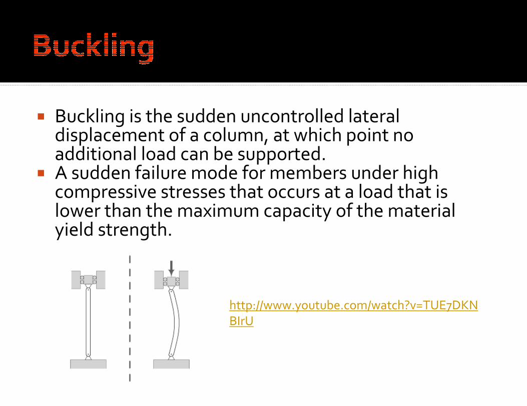
Buckling is the sudden uncontrolled lateral displacement of a column, at which point no additional load can be supported.
A sudden failure mode for members under high compressive stresses that occurs at a load that is lower than the maximum capacity of the material yield strength.
http://www.youtube.com/watch?v=TUE7DKN
BIrU
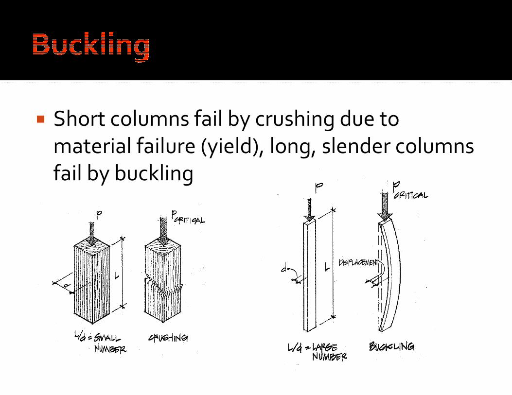
Short columns fail by crushing due to
material failure (yield), long, slender columns
fail by buckling

Since short columns fail by crushing (material
failure) the formula for the compressive
stress is simply:
allowableactual
aA
Pσσ ≤=

Since short columns fail by crushing (material
failure) the formula for the compressive
stress is simply:
allowableactual
aA
Pσσ ≤=
Axial Load on Column
Allowable Axial Stress
Column Cross-
Sectional Area
Actual Axial Stress

Since short columns fail by crushing (material
failure) the formula for the compressive
stress is simply:
allowable
actualrequired
PA
σ≥
Axial Load on Column
Allowable Axial Stress Column Cross-
Sectional Area

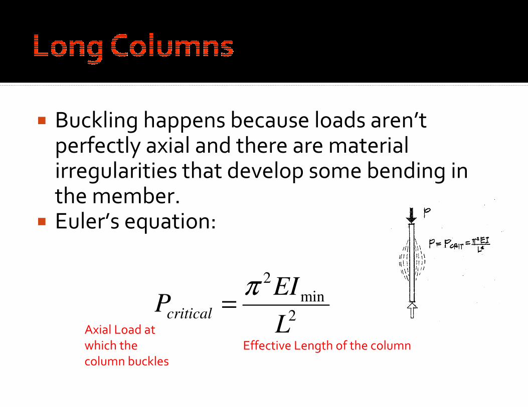
Buckling happens because loads aren’t perfectly axial and there are material irregularities that develop some bending in the member.
Euler’s equation:
2
min
2
L
EIPcritical
π=
Buckling happens because loads aren’t perfectly axial and there are material irregularities that develop some bending in the member.
Euler’s equation:
2
min
2
L
EIPcritical
π=
Effective Length of the column
Axial Load at
which the
column buckles

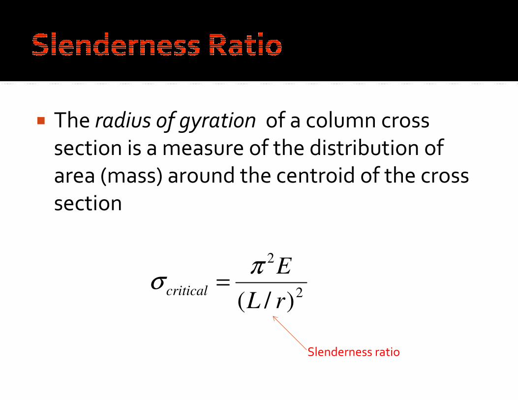
The radius of gyration of a column cross
section is a measure of the distribution of
area (mass) around the centroid of the cross
section
2ArI
A
Ir
=
=
Radius of gyration Moment of Inertia (smallest)
Cross-Sectional Area

The radius of gyration of a column cross
section is a measure of the distribution of
area (mass) around the centroid of the cross
section
2
2
2
22
2
min
2
)/(
)(
rL
E
AL
ArE
LA
EI
A
Pcriticalcritical
πππσ ====
2ArI =
The radius of gyration of a column cross
section is a measure of the distribution of
area (mass) around the centroid of the cross
section
2
2
)/( rL
Ecritical
πσ =
Slenderness ratio

For columns, the radius of gyration and moment of inertia that matter are the smaller ones.
The higher the slenderness ratio (long, thin column), the lower the load at which the column will buckle
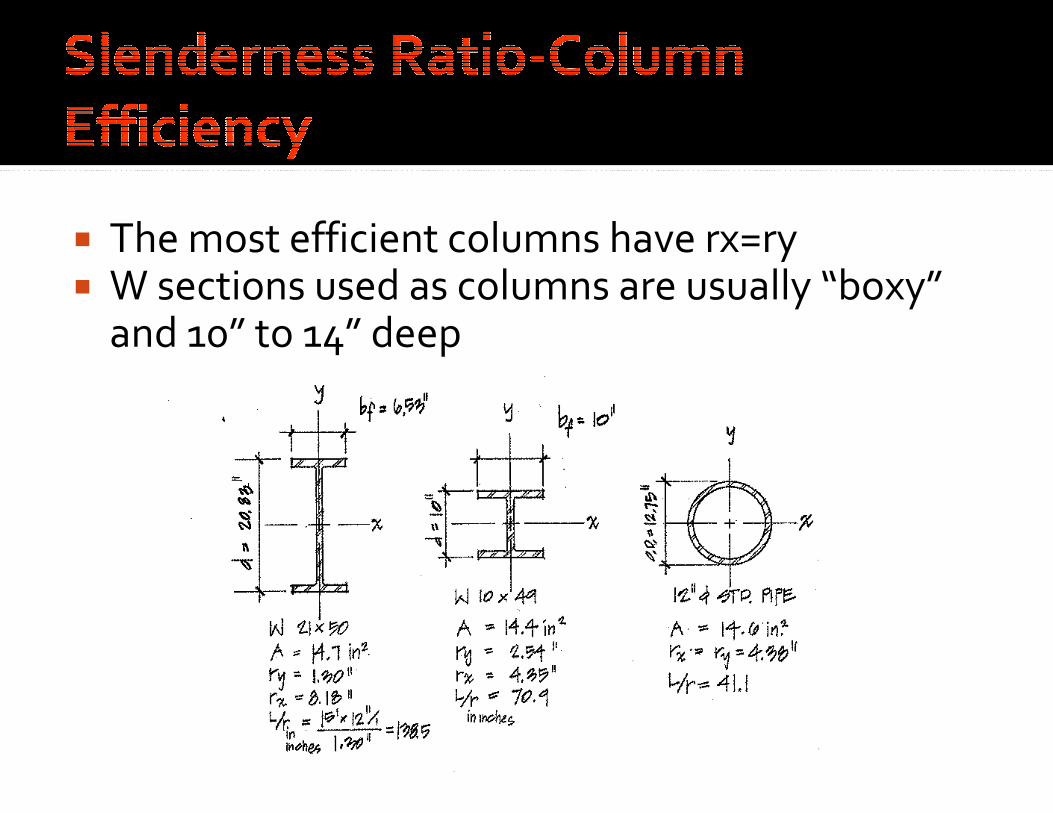
The most efficient columns have rx=ry W sections used as columns are usually “boxy”
and 10” to 14” deep

Determine the critical buckling stress for a 30’
long w12x65 steel column. Assume simple pin
connections at the top and bottom.
Fy=36ksi (A36 steel)
E=29,000 ksi
rx=5.28”
ry=3.02”

Determine the critical buckling stress for a 30’
long w12x65 steel column. Assume simple pin
connections at the top and bottom.
Fy=36ksi (A36 steel)
E=29,000 ksi
rx=5.28”
ry=3.02”
2
2
)( rL
Ecrit
πσ =
2.119
2.11902.3
)1230(
19.6828.5
)1230(
Use
ininx
rL
ininx
rL
y
x
==
==

Determine the critical buckling stress for a 30’
long w12x65 steel column. Assume simple pin
connections at the top and bottom.
Fy=36ksi (A36 steel)
E=29,000 ksi
rx=5.28”
ry=3.02”
ksi
ksi
rL
Ecrit
1.20
)2.119(
)000,29(
)(
2
2
2
2
=
=
=
π
πσ
In the simple analysis, columns were assumed
to be pinned at either end, so the column
would buckle in a smooth curve.
The length that is free to buckle is greatly
influenced by the end supports.
A K factor is used to increase or reduce the
effective length of the column to take the end
supports into account.
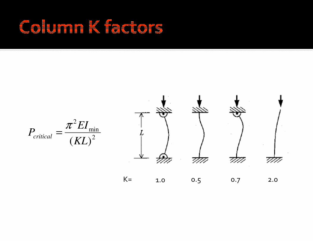
K= 1.0 0.5 0.7 2.0
2
min
2
)(KL
EIPcritical
π=
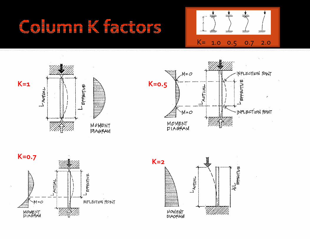
K= 1.0 0.5 0.7 2.0
K=1
K=0.7 K=2
K=0.5

Just as rigid end connections reduce the buckling length of a column, lateral bracing can also increase the column capacity by reducing the buckling length.
Lateral bracing is usually provided in the weak buckling direction

Lb
Lb
2
2
)(KL
EIPcritical
π=

2
2
)(KL
EIPcritical
π=

Slenderness ratios
must be calculated
for both axes to
determine which
direction governs
2
2
)(KL
EIPcritical
π=

Determine the critical buckling load for a 4x8 S4S Douglas Fir column that is 18’ long and braced at midheight against the weak direction of buckling. E=1,300 ksi

Determine the critical buckling load for a 4x6 S4S Douglas Fir column that is 18’ long and braced at midheight against the weak direction of buckling. E=1,300 ksi
6

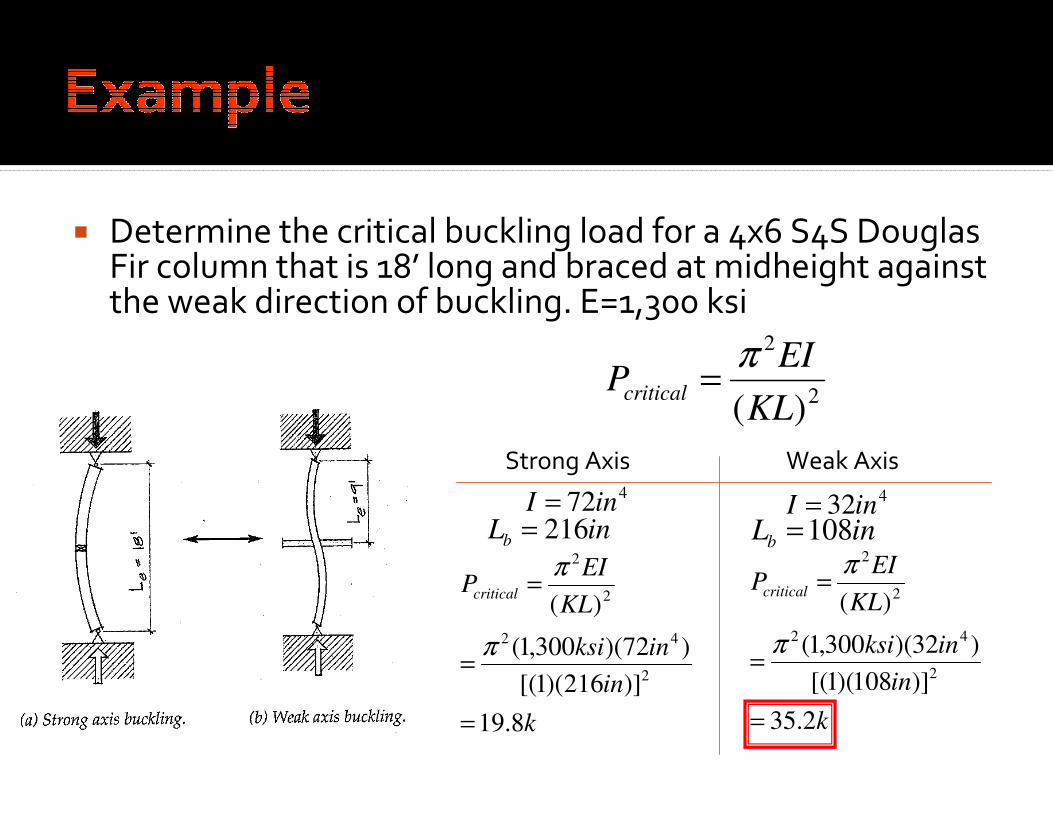
Determine the critical buckling load for a 4x6 S4S Douglas Fir column that is 18’ long and braced at midheight against the weak direction of buckling. E=1,300 ksi
2
2
)(KL
EIPcritical
π=

Determine the critical buckling load for a 4x6 S4S Douglas Fir column that is 18’ long and braced at midheight against the weak direction of buckling. E=1,300 ksi
2
2
)(KL
EIPcritical
π=
Strong Axis Weak Axis
4
3
3
72
)6)(4)(12/1(
121
in
bhI
=
=
=
4
3
3
32
)4)(6)(12/1(
121
in
bhI
=
=
=

Determine the critical buckling load for a 4x6 S4S Douglas Fir column that is 18’ long and braced at midheight against the weak direction of buckling. E=1,300 ksi
2
2
)(KL
EIPcritical
π=
Strong Axis Weak Axis
in
ftinxLb
216
)/12('18
=
=
in
ftinxLb
108
)/12('9
=
=
4
3
3
72
)6)(4)(12/1(
121
in
bhI
=
=
=
4
3
3
32
)4)(6)(12/1(
121
in
bhI
=
=
=

Determine the critical buckling load for a 4x6 S4S Douglas Fir column that is 18’ long and braced at midheight against the weak direction of buckling. E=1,300 ksi
2
2
)(KL
EIPcritical
π=
Strong Axis Weak Axis
432inI =
472inI =
inLb 216= inLb 108=
k
in
inksi
KL
EIPcritical
8.19
)]216)(1[(
)72)(300,1(
)(
2
42
2
2
=
=
=
π
π
k
in
inksi
KL
EIPcritical
2.35
)]108)(1[(
)32)(300,1(
)(
2
42
2
2
=
=
=
π
π

What are the two conditions that need to be investigated?

What are the two conditions that need to be investigated?
Weak Axis

What are the two conditions that need to be investigated?
Weak Axis
Strong Axis

In reality columns do not transition abruptly from short (crushing) to long (buckling.
There is an intermediate column range in which columns fail by a combination of buckling and crushing.
The analysis and design of steel columns takes this into account

AISC only recognizes two types of columns
for design, short/intermediate and long
The value for Kl/r where columns transition
from short/intermediate to long is known a Cc
and defined as:
y
cF
EC 71.4=

y
cF
EC 71.4=
)50(43.113 ksiCc =
)36(78.133 ksiCc =
Cc is the theoretical
value between
inelastic and elastic
behavior.

)50(43.113 ksir
KL≤
)50(43.113 ksir
KLCc ==
)50(43.113 ksir
KL>
y
F
F
cr FF e
y
= 658.0
2
2
==
r
KL
EFecritical
πσ
ecr FF 877.0=
)(67.1 ASDc =Ω

Design K-Values from AISC
Table 4-1
Table C-36
Table C-50


Find the maximum Axial Load on your column-P(actual) Find the KLx and KLy Use Table 4-1 to find a trial section using the KLy (Tables are only
for KLy) Find KLx (equivalent) by using rx/ry from table Use LARGEST KL/r for the rest of the design Using the largest KL/r, enter Table 9.1 or 9.2 to obtain a respective
Fa Calculate the P(allowable)=(Fa)x(A) of the trial section Check to see if P(allowable)>P(actual) If the P(allowable) is too low, pick a larger section and repeat If P(allowable) is larger then P(actual), check
efficiency…P(actual)/P(allowable) should be around 0.8 or 0.9 If your column seems overdesigned, pick a smaller section and
start again Repeat until you find an ADEQUATE and EFFICIENT section.


Find the maximum Axial Load on your column-P(actual) Find the KLx and KLy Use Table 4-1 to find a trial section using the KLy (Tables are only
for KLy) Find KLx (equivalent) by using rx/ry from table Use LARGEST KL/r for the rest of the design Figure out which of the two equations you need to use based on
Cc Calculate F(critical) using the appropriate equation Calculate the P(allowable)=(Fcr/Ωc)x(A) of the trial section Check to see if P(allowable)>P(actual) If the P(allowable) is too low, pick a larger section and repeat If P(allowable) is larger then P(actual), check
efficiency…P(actual)/P(allowable) should be around 0.8 or 0.9 If your column seems overdesigned, pick a smaller section and
start again Repeat until you find an ADEQUATE and EFFICIENT section.


