84
NZ Series Heavy Duty NFPA Tie Rod Cylinders Catalog Series NZ

NZ Series Heavy Duty NFPA Tie Rod Cylinders
Catalog Series NZ

EATON NZ Series Heavy Duty NFPA Tie Rod Cylinders V-CYTR-MC002-E2 March 20132
USER RESPONSIBILITY - IMPROPER SELECTION, USE OR MAINTENANCE OF THE SYSTEM, PRODUCTS OR COMPONENTS DESCRIBED IN THIS CATALOG MAY CAUSE OR RESULT IN DEATH, PERSONAL INJURY AND/OR PROPERTY DAMAGE.
This document and other information from Eaton Corporation, its subsidiaries and authorized distributors pro-vide product or system options for users having technical expertise. This product is not intended for users who do not have technical expertise.
The user, through its own analysis and testing, is solely responsible for making the final selection of the system and components and assuring that all performance, endur-ance, maintenance, safety and warning requirements of the application are met. The user must analyze all aspects of the application, follow applicable industry standards, and follow the information concerning the product in the current prod-uct catalog and in any other materials provided from Eaton or its subsidiaries or authorized distributors.
To the extent that Eaton or its subsidiaries or authorized distributors provide component or system options based upon data or specifications provided by the user, the user is responsible for determining that such data and specifications are suitable and sufficient for all applications and all reason-able foreseeable uses of the components or systems.
Disclaimer and Warning

3EATON NZ Series Heavy Duty NFPA Tie Rod Cylinders V-CYTR-MC002-E2 March 2013
Feature . . . . . . . . . . . . . . . . . . . . . . . . . . . . . . . . . . . . . . . . . . . . . . . . . . . . . . . . . . . . . . . . . . . . . . . . . . . . . . . . . . . . . . . . . . . . .4.How to order . . . . . . . . . . . . . . . . . . . . . . . . . . . . . . . . . . . . . . . . . . . . . . . . . . . . . . . . . . . . . . . . . . . . . . . . . . . . . . . . . . . . . . . .5Model code . . . . . . . . . . . . . . . . . . . . . . . . . . . . . . . . . . . . . . . . . . . . . . . . . . . . . . . . . . . . . . . . . . . . . . . . . . . . . . . . . . . . . . . . .6NZ Standard Mounting Styles . . . . . . . . . . . . . . . . . . . . . . . . . . . . . . . . . . . . . . . . . . . . . . . . . . . . . . . . . . . . . . . . . . . . . . . . . . .8
Mounting Style & Installation Dimensions
NZ01 Side Lug Mounts . . . . . . . . . . . . . . . . . . . . . . . . . . . . . . . . . . . . . . . . . . . . . . . . . . . . . . . . . . . . . . . . . . . . . . . . . . . . . . .10NZ02 Side Tapped Mounts . . . . . . . . . . . . . . . . . . . . . . . . . . . . . . . . . . . . . . . . . . . . . . . . . . . . . . . . . . . . . . . . . . . . . . . . . . . .12NZ03 End Lug Mounts . . . . . . . . . . . . . . . . . . . . . . . . . . . . . . . . . . . . . . . . . . . . . . . . . . . . . . . . . . . . . . . . . . . . . . . . . . . . . . .14.NZ04. Keyed Side Lug Mounts . . . . . . . . . . . . . . . . . . . . . . . . . . . . . . . . . . . . . . . . . . . . . . . . . . . . . . . . . . . . . . . . . . . . . . . . .16NZ05 Keyed Tapped Mounts . . . . . . . . . . . . . . . . . . . . . . . . . . . . . . . . . . . . . . . . . . . . . . . . . . . . . . . . . . . . . . . . . . . . . . . . . . .18NZ07 Head Rectangular Flange Mounts . . . . . . . . . . . . . . . . . . . . . . . . . . . . . . . . . . . . . . . . . . . . . . . . . . . . . . . . . . . . . . . . . .20NZ08 Head Square Flange Mounts . . . . . . . . . . . . . . . . . . . . . . . . . . . . . . . . . . . . . . . . . . . . . . . . . . . . . . . . . . . . . . . . . . . . .22NZ09 Head Rectangle Mounts . . . . . . . . . . . . . . . . . . . . . . . . . . . . . . . . . . . . . . . . . . . . . . . . . . . . . . . . . . . . . . . . . . . . . . . . .24.NZ10 Cap Fixed Clevis Mounts . . . . . . . . . . . . . . . . . . . . . . . . . . . . . . . . . . . . . . . . . . . . . . . . . . . . . . . . . . . . . . . . . . . . . . . . .26NZ11 Cap Spherical Bearing Mounts . . . . . . . . . . . . . . . . . . . . . . . . . . . . . . . . . . . . . . . . . . . . . . . . . . . . . . . . . . . . . . . . . . . .28NZ12 Cap Rectangular Flange Mounts . . . . . . . . . . . . . . . . . . . . . . . . . . . . . . . . . . . . . . . . . . . . . . . . . . . . . . . . . . . . . . . . . . .30NZ13 Cap Square Flange Mounts . . . . . . . . . . . . . . . . . . . . . . . . . . . . . . . . . . . . . . . . . . . . . . . . . . . . . . . . . . . . . . . . . . . . . . .32NZ14. Cap Rectangle Mounts . . . . . . . . . . . . . . . . . . . . . . . . . . . . . . . . . . . . . . . . . . . . . . . . . . . . . . . . . . . . . . . . . . . . . . . . . .34.NZ15 Intermediate Trunnion Mounts . . . . . . . . . . . . . . . . . . . . . . . . . . . . . . . . . . . . . . . . . . . . . . . . . . . . . . . . . . . . . . . . . . . .36NZ16 Cap Trunnion Mounts . . . . . . . . . . . . . . . . . . . . . . . . . . . . . . . . . . . . . . . . . . . . . . . . . . . . . . . . . . . . . . . . . . . . . . . . . . .38NZ17 Head Trunnion Mounts . . . . . . . . . . . . . . . . . . . . . . . . . . . . . . . . . . . . . . . . . . . . . . . . . . . . . . . . . . . . . . . . . . . . . . . . . .4.0NZ19 Center Lug Mounts . . . . . . . . . . . . . . . . . . . . . . . . . . . . . . . . . . . . . . . . . . . . . . . . . . . . . . . . . . . . . . . . . . . . . . . . . . . . .4.2NZ21 Cap End Extended Tie Rod Mounts . . . . . . . . . . . . . . . . . . . . . . . . . . . . . . . . . . . . . . . . . . . . . . . . . . . . . . . . . . . . . . . .4.4.NZ22 Head End Extended Tie Rod Mounts . . . . . . . . . . . . . . . . . . . . . . . . . . . . . . . . . . . . . . . . . . . . . . . . . . . . . . . . . . . . . . .4.6NZ23 Both End Extended Tie Rod Mounts . . . . . . . . . . . . . . . . . . . . . . . . . . . . . . . . . . . . . . . . . . . . . . . . . . . . . . . . . . . . . . . .4.8NZ24. No Mounts . . . . . . . . . . . . . . . . . . . . . . . . . . . . . . . . . . . . . . . . . . . . . . . . . . . . . . . . . . . . . . . . . . . . . . . . . . . . . . . . . . .50NZ25 Double Rod Side Lug Mounts . . . . . . . . . . . . . . . . . . . . . . . . . . . . . . . . . . . . . . . . . . . . . . . . . . . . . . . . . . . . . . . . . . . . .52NZ4.7 Cap Fixed Mono Clevis Mounts . . . . . . . . . . . . . . . . . . . . . . . . . . . . . . . . . . . . . . . . . . . . . . . . . . . . . . . . . . . . . . . . . . .54.NZ4.8 Cap Detachable Eye Mounts . . . . . . . . . . . . . . . . . . . . . . . . . . . . . . . . . . . . . . . . . . . . . . . . . . . . . . . . . . . . . . . . . . . . . .56NZ50 Cap Detachable Mounts . . . . . . . . . . . . . . . . . . . . . . . . . . . . . . . . . . . . . . . . . . . . . . . . . . . . . . . . . . . . . . . . . . . . . . . . .58
Technical Data
Accessories . . . . . . . . . . . . . . . . . . . . . . . . . . . . . . . . . . . . . . . . . . . . . . . . . . . . . . . . . . . . . . . . . . . . . . . . . . . . . . . . . . . . . . . .60Rod End Couplings . . . . . . . . . . . . . . . . . . . . . . . . . . . . . . . . . . . . . . . . . . . . . . . . . . . . . . . . . . . . . . . . . . . . . . . . . . . . . . . . . .64.Self Aligning Coupler . . . . . . . . . . . . . . . . . . . . . . . . . . . . . . . . . . . . . . . . . . . . . . . . . . . . . . . . . . . . . . . . . . . . . . . . . . . . . . . . .65Rod End Types . . . . . . . . . . . . . . . . . . . . . . . . . . . . . . . . . . . . . . . . . . . . . . . . . . . . . . . . . . . . . . . . . . . . . . . . . . . . . . . . . . . . . .66Port type and size . . . . . . . . . . . . . . . . . . . . . . . . . . . . . . . . . . . . . . . . . . . . . . . . . . . . . . . . . . . . . . . . . . . . . . . . . . . . . . . . . . .68Port Selections . . . . . . . . . . . . . . . . . . . . . . . . . . . . . . . . . . . . . . . . . . . . . . . . . . . . . . . . . . . . . . . . . . . . . . . . . . . . . . . . . . . . . .70Port Locations . . . . . . . . . . . . . . . . . . . . . . . . . . . . . . . . . . . . . . . . . . . . . . . . . . . . . . . . . . . . . . . . . . . . . . . . . . . . . . . . . . . . . .71Sealing system . . . . . . . . . . . . . . . . . . . . . . . . . . . . . . . . . . . . . . . . . . . . . . . . . . . . . . . . . . . . . . . . . . . . . . . . . . . . . . . . . . . . .72Proximity switch . . . . . . . . . . . . . . . . . . . . . . . . . . . . . . . . . . . . . . . . . . . . . . . . . . . . . . . . . . . . . . . . . . . . . . . . . . . . . . . . . . . . 74.Bore Rod & Diameter, Cylinder Size Selection . . . . . . . . . . . . . . . . . . . . . . . . . . . . . . . . . . . . . . . . . . . . . . . . . . . . . . . . . . . . .77Maximum Allowable Push Stroke . . . . . . . . . . . . . . . . . . . . . . . . . . . . . . . . . . . . . . . . . . . . . . . . . . . . . . . . . . . . . . . . . . . . . . .78Technical Data, Cushion . . . . . . . . . . . . . . . . . . . . . . . . . . . . . . . . . . . . . . . . . . . . . . . . . . . . . . . . . . . . . . . . . . . . . . . . . . . . . . .79
Table of Contents

EATON NZ Series Heavy Duty NFPA Tie Rod Cylinders V-CYTR-MC002-E2 March 20134
Features
2
1
3
4
5
6
7
1. Rod Cartridge Assembly:
Machined to maximum bearing support and wear resistance. Unitized, thread-less assembly is pilot-fitted into the head on a precision bored diameter to assure true concentricity.
2. Special Wearbands:
Metal-to-metal contact is eliminated, providing supe-rior wearability, increased load carrying capability, and prolonged cylinder life.
3. Piston Sealing System:
This system offers not only a selection of highly efficient seal materials, but also an extra wide wearband that rides smoothly within the precision-honed cylinder body to provide extended piston seal life.
4. Square Head Tie-Rod Design:
Suitable for nominal working pressure up to 3000 psi.
5. Piston Rod:
Hard chrome plated piston rod in a variety of diameters between 1 and 5 1/2 inches provides maximum durability and extends seal life. Case hardened rods are standard up to 4. inches, and are an option for 4. 1/2 inch and larger rods.
6. Captive Screws:
Inadvertent removal of cush-ion screws is prevented, while still allowing a full range of adjustment.
7. Fully Adjustable Cushioning System:
This design has been engineered to provide the ability to tune the cushion performance for an opti-mized deceleration profile. Our patented floating ring cushion seal or an alternate ball check design allows maximum acceleration. This excellent acceleration profile translates into faster cycle times and increased machine production.
8. Global Design:
Engineered for ANSI B93.15/NFPA interchangeability with the durability required for heavy-duty applications.
9. SureSeal Sealing System:
Carefully selected wiper and seal combinations are mated with a hard chrome plated piston rod to deliver exceptional all-around performance and durability.
10. Full Range of Ports:
Including SAE, BSPP, and metric to ISO 614.9 and DIN standard 3852 to provide the broadest piping flexibility.
11. Teflon Tube Seals:
Superior design to prevent leakage Compatible with virtually all fluids Operating temperatures to 500°F
12. Bore Size Range:
Cylinder bores available between 1-1/2 and 8 inches.

5EATON NZ Series Heavy Duty NFPA Tie Rod Cylinders V-CYTR-MC002-E2 March 2013
WARNING It is the user’s responsibility to select the correct sys-tem, product or components.
How To Order
Standard Cylinders
Eaton has created an easy system for ordering Vickers™ Series NZ cylinders, devel-oped to improve our service to you. The Standard model code consists of sixteen alpha-numeric digits which fully describe the most common standard options offered on Series NZ cylin-ders.
To specify your Series NZ cylinder, review the follow-ing pages for a full descrip-tion of each option available and select the desired code.
This model code system will:
Simplify the re-order pro-cess.
Each Vickers™ Series NZ cylinder is assigned a six-teen digit model code. That code is unique to a particular cylinder description. That way, when you re-order your Series NZ cylinder, you’re assured of exactly the same top quality cylinder design.
Improve identification.
Every Series NZ cylinder has its sixteen digit model code clearly marked on the prod-uct, impression stamped in the metal head or cap. Each sixteen digit code com-pletely describes a specific cylinder. This allows seals and replacement compo-nents to be easily identified in the field.
Facilitate communications.
This fully descriptive model code system allows you to work directly with your local Eaton sales engineer to identify and service your Vickers cylinder.
NOTE
See pages 6 and 7 for a summary of model code options.
Custom Cylinders
New Cylinders
Although the model code has been arranged to cover the vast majority of avail-able options, there will be occasions when you require an option which cannot be coded.
When specifying such an option, enter an “X” for the appropriate item in the six-teen digit model code, then describe your requirements. For example, if you have an application which requires a custom thread on the end of the piston rod, enter an “X” for item 7. Then add a full description at the end of the model code, such as “With 3.25 inch total rod projection and M22 x 1,5 thread 1.375 inches long.” The cylinder will then be given a unique six digit design number on receipt of order (as explained below).
If more than one of the available options represent-ed in items 15 and 16 are required, add the appropri-ate codes as a suffix. The cylinder will then be given a unique six digit design num-ber on receipt of order (as explained below).
Replacement Cylinders
Every custom Eaton cylinder is assigned a unique design number. A Custom cylinder will have 22 digits vs. 16 for the standard cylinder. The design number is contained in the last six digits of the model code, and position 17 is always an alpha character. In other words, the design number begins after position 16. When ordering a replace-ment cylinder, simply give the model code or the six digit design number to your local Eaton Cylinder Sales representative.
Replacement Parts
Each design number is stored in a quick retrieval computerized storage sys-tem. This gives our field sales representatives rapid access to assist you in iden-tifying and specifying genu-ine Eaton replacement parts.

EATON NZ Series Heavy Duty NFPA Tie Rod Cylinders V-CYTR-MC002-E2 March 20136
Model Codes
NZ 0 9 KM 1 N 1 K W 99A PR
1, 2 SeriesNZ – ANSI B93.15/NFPA
Interchageable Hydraulic cylinder
3, 4. Mounting Styles01 – Side Lug MS202 – Side Tapped MS4.03 – End Lug Mount MS704 – Keyed Side Lug05 – Keyed Tapped 07 – Head Rectangular
Flange MF1 08 – Head Square
Flange MF509 – Head Rectangular ME510 – Clevis MP111 – Spherical Bushing MP512 – Cap Rectangular
Flange MF213 – Cap Square
Flange MF614 – Cap Rectangular ME615 – Intermediate
Trunnion MT4.16 – Cap Trunnion MT217 – Head Trunnion MT119 – Centerline Lug MS321 – Cap End Extended Tie Rod MX222 – Head End Extended Tie Rod MX323 – Both Ends Extended Tie Rod MX124 – No Mount - 25 – Double Rod,
Side Lug -26 – Double Rod,
Tapped - 27 – Double Rod,
End Lug -28 – Double Rod,
Keyed Side Lug - 29 – Double Rod,
Keyed Tapped - 31 – Double Rod,
Rectangular Flange -
32 – Double Rod, Square Flange -
33 – Double Rod, Head Rectangular -
34 – Double Rod, Intermediate Trunnion -
35 – Double Rod, Head Trunnion -
37 – Double Rod, Centerline Lug -
39 – Double Rod, Extended Tie Rod -
40 – Double Rod, Both Ends Extended Tie Rod -
41 – Double Rod, No Mount -
47 – Cap Fixed Eye MP348 – Detachable Eye MP4. 50 – Detachable Clevis MP2
5, 6 Bore and Rod Size Combinations
Code Bore(in) Rod(in) CC 1-1/2 5/8CE 1-1/2 1
DE 2 1DH 2 1-3/8
EE 2-1/2 1EH 2-1/2 1-3/8EL 2-1/2 1-3/4.
GH 3-1/4. 1-3/8GL 3-1/4. 1-3/4.GM 3-1/4. 2
HL 4. 1-3/4.HM 4. 2HP 4. 2-1/2
KM 5 2KP 5 2-1/2KU 5 3KV 5 3-1/2
LP 6 2-1/2LU 6 3LV 6 3-1/2LW 6 4.
MU 7 3MV 7 3-1/2MW 7 4.MY 7 4.-1/2MZ 7 5
NV 8 3-1/2NW 8 4.NY 8 4.-1/2NZ 8 5N1 8 5-1/2
1, 2 3, 4. 5, 6 7 8 9 10 11 12, 13, 14. 15, 16
7 Rod End TypeCode Type1 Short Female Metric
Thd. 2 Short Female UN Thd.5 Small Male UN Thd. 6 Plain No Attachment7 Small Male Metric Thd. 9 Intermediate Male UN Thd.0 Intermediate Male
Metric G Grooved EndK Extended Small Male UN Thd. L Extended Small Male Metric Thd.M Extended Intermedi- ate Male UN Thd. N Extended Intermedi- ate Male Metric Thd.R Studded Small Male UN Thd.
8 Seal Options N – Normal L – Low FrictionT – High TemperatureC – Normal with Cast Iron Piston Rings R – High Temperature with Cast Iron Piston Rings
9 Port Options 1 – Standard NPTF*2 – Oversize NPTF*3 – SAE/UN O-ring4 – Oversize SAE/UN5 – NFPA Standard SAE/UN6 – SAE 4.-Bolt Flange7 – BSPP8 – Oversize BSPP9 – Metric0 – Oversize MetricA – ISO 614.9B – Oversize ISO 614.9K – Undersize ISO 614.9C – Undersize 4.-Bolt FlangeD – Undersize NPTF*G – Undersize Metric M – Standard Manifold
* Not recommended for maximum
reliabilty on new applications.
10 Port LocationsPorts are located as shown in Rod end type section when viewing cylinder from head end (mounting end of double rod cylinders).
Code Head CapK 1 1L 1 2M 1 3N 1 4.P 2 1 R 2 2S 2 3T 2 4.U 3 1V 3 2W 3 3Y 3 4.1 4. 12 4. 23 4. 34 4. 4.5 1 56 2 57 3 58 4. 5

7EATON NZ Series Heavy Duty NFPA Tie Rod Cylinders V-CYTR-MC002-E2 March 2013
11 Cushion Location Cushions are located as shown in Rod end type sec-tion when viewing cylinder from head end (mounting end of double rod cylinders). “–” in table indicates no cushion.
Code Head CapA – –B – 1C – 2D – 3E – 4.F 1 –G 2 –H 3 –J 4. –K 1 1L 1 2M 1 3N 1 4.P 2 1R 2 2S 2 3T 2 4.U 3 1V 3 2W 3 3Y 3 4.1 4. 12 4. 23 4. 34 4. 4.
Double Rod Cylinders:“Head” = “Mounting End”“Cap” = Non-mounting End
12, 13, 14. Cylinder Stroke Items 12 and 13 indicate stroke length from 00 inches through 99 inches. Item 14. indicates fraction of an inch per the following codes:
Code Fraction Code Fraction0 0 8 1/21 1/16 9 9/162 1/8 A 5/83 3/16 B 11/164 1/4. C 3/4.5 5/16 D 13/166 3/8 E 7/87 7/16 F 15/16
Model Codes
NZ 0 9 KM 1 N 1 K W 99A PR
1, 2 3, 4. 5, 6 7 8 9 10 11 12, 13, 14. 15, 16
15, 16 Extra Rod ProjectionItem 15 indicates inches from 0 thru 9.Item 16 indicates fraction of an inch per the following codes:
–––––––––––– OR ––––––––––– Proximity Switch,Gland Drain, Air Bleeder / flats / rod material / Limit switch / stop tube / keyed piston
Code No. of A/C Flat*F4 4.F6 6
* Only upto 3.5” Rod.
Gland DrainCode Head Cap* GB - 1* GC - 2* GD - 3 * GE - 4. GF 1 - GG 2 - GH 3 - GJ 4. -* GK 1 1* GG 1 2* GM 1 3* GN 1 4.* GP 2 1* GR 2 2* GS 2 3* GT 2 4.* GU 3 1* GV 3 2* GW 3 3* GY 3 4.* G1 4. 1* G2 4. 2* G3 4. 3* G4 4. 4.
* Codes applicable to Double Rods only
Proximity/PositionsCode Head Cap PB - 1 PC - 2 PD - 3 PE - 4. PF 1 -
PG 2 - PH 3 - PJ 4. - PK 1 1 PL 1 2 PM 1 3 PN 1 4. PP 2 1 PR 2 2 PS 2 3 PT 2 4. PU 3 1 PV 3 2 PW 3 3 PY 3 4. P1 4. 1 P2 4. 2 P3 4. 3 P4 4. 4.
** P5 1 5** P6 2 5** P7 3 5** P8 4. 5
** Applicable for Single rods, Except 1.50” Bore Cushioned option
Air Bleed/PositionsCode Head CapHB - 1HC - 2HD - 3HE - 4.HF 1 -HG 2 -HH 3 -HJ 4. -HK 1 1HL 1 2HM 1 3HN 1 4.HP 2 1HR 2 2HS 2 3HT 2 4.HU 3 1HV 3 2HW 3 3HY 3 4.H1 4. 1H2 4. 2H3 4. 3H4 4. 4.
Double Rod Cylinders:“Head” = “Mounting End”“Cap” = Non-mounting End
Stop Tube/PositionsCode Length in inches S1 1 S2 2 S3 3 S4 4. S5 5 S6 6 S7 7 S8 8 S9 9 S0 10 SA 11 SB 12 SC 13 SD 14. SE 15 SF 16 SG 17 SH 18 SJ 19 SK 20
Keyed Piston to RodCode TypeKG Grub Screw KS Weld Piston to rod
Rod Material OptionsCode Type* RP Thick Chrome Plate RS Stainless Steel 17-4.** RT Stainless Steel 303
* .002 Chrome thickness
** Consult factory for pressure Rating

EATON NZ Series Heavy Duty NFPA Tie Rod Cylinders V-CYTR-MC002-E2 March 20138
Mounting Styles
Available Mountings
The variety of standard ANSI/NFPA mountings avail-able in the Series NZ gives you a broad selection to match the proper mount to your application. Eaton offers rigid mounts (including side lug mounts, flange mounts, and extended tie rod mounts) and swivel mounts (including clevis mounts and trunnion mounts). For custom mounts, enter “XX”
for model code item 2, and give a detailed description with drawings. Series NZ cylinders are available in all mounting styles listed.
Selecting the Proper Mounting
Just as the cylinder bore must be sized to provide the proper force for an applica-tion, a cylinder mounting that can absorb these appli-cation forces must also be specified. CAUTION In the mounting informa-tion, some mounts have been downrated to mini-mize deflection. For appli-
cations where the motion is linear and parallel to the cylinder rod motion, a rigid mount is recom-mended. For curvilinear motion, a swivel mount should be chosen. The spe-cifics of each application dictate the correct mount-ing style it is the user’s responsibility to make the correct determination.
NZ01Side lugANSI MS2
NZ02Side TappedANSI MS4.
NZ03End lugANSI MS7
NZ04Keyed Side Lug
LH
E
US
TS
E
ST
RM
SB BOLT
2
1
4
3
2425 W. Michigan Ave. - Jackson, MI 49202
Drawn By:
Checked By:
Scale:
Date:
CUSTOMER:
DWG. NO.:
DWG. TITLE:
DISTRIBUTOR:
Finish:
Finish Spec.:
THIRD ANGLE PROJECTIONNOTICE TO PERSONS RECEIVING THIS DRAWING AND/OR TECHNICAL INFORMATIONEaton Corporation claims proprietary rights in the information disclosed hereon. This document
is issued in confidence and is property of Eaton Corporation. This document is not to be reproduced orused to manufacture anything shown hereon without the expressed written consent of Eaton Corporation.
REV.NO. REVISION/DESCRIPTION DATE BY
REV.
XXX
< Title Here >
< Part No. Here >
XXX
XXX
XX-XX-XXReviewed for Classification of Characteristics per ESP-042
A
ISSUEDA
K J G
SY SU SU
STROKE+SS XS
SY
STROKE+ZB
F
V
C
B
MM
G1
NZ05Keyed Side Tapped
NZ07Head Rectangular flangeANSI MF1(Maximum working pressure 800 PSI)
NZ08Head Square flangeANSI MF5(Maximum working pressure 1500 PSI)
NZ09Head RectangularANSI ME5
NZ10Cap ClevisANSI MP1
NZ11Cap Spherical bearing(Maximum working presure per Bore on page 28.)
NZ12Cap Rectangular flangeANSI MF2 (Maximum working pressure 800 PSI)
NZ13Cap Square flangeANSI MF6 (Maximum working pressure 1500 PSI)

9EATON NZ Series Heavy Duty NFPA Tie Rod Cylinders V-CYTR-MC002-E2 March 2013
NZ14Cap RectangularANSI ME6
NZ15Intermediate TrunnionANSI MT4.
NZ16Cap TrunnionANSI MT2
NZ17Head TrunnionANSI MT1
NZ19Center LugANSI MS3
NZ21Cap Extended Tie rodANSI MX2
NZ22Head Extended Tie rodANSI MX3
NZ23Both Ends Extended Tie rodANSI MX1
NZ24No Mount
NZ25Double rod, Side Lug
NZ47Cap Fixed EyeANSI MP3
NZ48Cap Detachable EyeANSI MP4.
Mounting Styles
NZ50Cap Detachable ClevisANSI MP2

EATON NZ Series Heavy Duty NFPA Tie Rod Cylinders V-CYTR-MC002-E2 March 201310
Mounting Style and InstallationDimensions – NZ01 Side Lug Mount
+ Plus Stroke† For Port and Switch at position 2 & 4 please refer page 71, Mounting Holes requires counter Bore
LH
E
US
TS
E
ST
RM
SB BOLT
1
2
3
4
XXX
< Title Here >
XXX
XXX
XX-XX-XXReviewed for Classification of Characteristics per ESP-042
K J G
SY SU SU
STROKE+SS XS
SY
STROKE+ZB
F
V
C
B
MM
G1
2425 W. Michigan Ave. - Jackson, MI 49202
Drawn By:
Checked By:
Scale:
Date:
CUSTOMER:
DWG. TITLE:
DISTRIBUTOR:
Finish:
Finish Spec.:
BoreRod Dia MM
B +.000/-.002 C E G J F V RM
LH ±.002 SB
1.50 0.63 1.124. 0.38 2.50 1.75 1.50 0.38 0.25 - 1.24.3 0.38
1.00 1.4.99 0.50 2.50 1.75 1.50 0.38 0.50 - 1.24.3 0.38
2.00 1.00 1.4.99 0.50 3.00 1.75 1.50 0.63 0.25 - 1.4.93 0.50
1.38 1.999 0.63 3.00 1.75 1.50 0.63 0.38 - 1.4.93 0.50
2.50 1.00 1.4.99 0.50 3.50 1.75 1.50 0.50 0.38 2.63 1.74.3 0.75
1.38 1.999 0.63 3.50 1.75 1.50 0.63 0.38 - 1.74.3 0.75
1.75 2.374. 0.75 3.50 1.75 1.50 0.63 0.50 1.74.3 0.75
3.25 1.38 1.999 0.63 4..50 2.00 1.75 0.59 0.4.1 3.25 2.24.3 0.75
1.75 2.374. 0.75 4..50 2.00 1.75 0.75 0.38 - 2.24.3 0.75
2.00 2.624. 0.88 4..50 2.00 1.75 0.75 0.38 - 2.24.3 0.75
4..00 1.75 2.374. 0.75 5.00 2.00 1.75 0.59 0.53 3.88 2.4.93 1.00
2.00 2.624. 0.88 5.00 2.00 1.75 0.59 0.53 4..00 2.4.93 1.00
2.50 3.124. 1.00 5.00 2.00 1.75 0.59 0.66 4..4.4. 2.4.93 1.00
5.00 2.00 2.624. 0.88 6.50 2.00 1.75 0.59 0.53 4..00 3.24.3 1.00
2.50 3.124. 1.00 6.50 2.00 1.75 0.59 0.66 4..4.4. 3.24.3 1.00
3.00 3.74.9 1.00 6.50 2.00 1.75 0.72 0.53 5.25 3.24.3 1.00
3.50 4..24.9 1.00 6.50 2.00 1.75 0.72 0.53 5.63 3.24.3 1.00
6.00 2.50 3.124. 1.00 7.50 2.25 2.25 0.59 0.66 4..4.4. 3.74.3 1.25
3.00 3.74.9 1.00 7.50 2.25 2.25 0.72 0.53 5.25 3.74.3 1.25
3.50 4..24.9 1.00 7.50 2.25 2.25 0.72 0.53 5.63 3.74.3 1.25
4..00 4..74.9 1.00 7.50 2.25 2.25 0.88 0.38 6.4.4. 3.74.3 1.25
7.00 3.00 3.74.9 1.00 8.50 2.75 2.75 0.72 0.53 5.25 4..24.3 1.50
3.50 4..24.9 1.00 8.50 2.75 2.75 0.72 0.53 5.63 4..24.3 1.50
4..00 4..74.9 1.00 8.50 2.75 2.75 0.88 0.38 6.4.4. 4..24.3 1.50
4..50 5.24.9 1.00 8.50 2.75 2.75 0.88 0.38 7.13 4..24.3 1.50
5.00 5.74.9 1.00 8.50 2.75 2.75 0.88 0.38 7.56 4..24.3 1.50
8.00 3.50 4..24.9 1.00 9.50 3.00 3.00 0.72 0.53 5.63 4..74.3 1.50
4..00 4..74.9 1.00 9.50 3.00 3.00 0.88 0.38 6.4.4. 4..74.3 1.50
4..50 5.24.9 1.00 9.50 3.00 3.00 0.88 0.38 7.13 4..74.3 1.50
5.00 5.74.9 1.00 9.50 3.00 3.00 0.88 0.38 7.56 4..74.3 1.50
5.50 6.24.9 1.00 9.50 3.00 3.00 0.88 0.38 8.38 4..74.3 1.50

11EATON NZ Series Heavy Duty NFPA Tie Rod Cylinders V-CYTR-MC002-E2 March 2013
Mounting Style and InstallationDimensions – NZ01 Side Lug Mount
+ Plus Stroke
Side lug mounts are for moving loads along a flat guided surface as in a car-riage along rails. The mount-ing surface should be flat and parallel to the centerline of the piston rod. The load should be guided to traverse along the centerline of the piston rod.
The frame on which the cylinder is mounted must be sufficiently rigid to resist bending moments. NOTE Limit operating pressure to 2320 psi for minimum deflec-
tion on 6, 7 and 8 inch bores. For strokes in excess of 30 inches, see “Stop tube selec-tion” on page 77.
WARNING With unsupported loads, the bearing must absorb more force. For these applications, the larger available rod is rec-ommended, and stop tubes should be considered.
Use high tensile socket head cap screws or hex head bolts tightened to the manufactur-er’s recommended torque.
For high shock applications, dowel pins or shear keys
should be incorporated in the mounting design. For these applications, consider a keyed side lug mount, NZ04..
For severe side load applica-tions, consult your local Eaton sales engineer.
WARNING Failure to mount the cylinder correctly on the frame may result in death, bodily injury and/or property damage.
LH
E
US
TS
E
ST
RM
SB BOLT
2
1
4
3
2425 W. Michigan Ave. - Jackson, MI 49202
Drawn By:
Checked By:
Scale:
Date:
CUSTOMER:
DWG. NO.:
DWG. TITLE:
DISTRIBUTOR:
Finish:
Finish Spec.:
THIRD ANGLE PROJECTIONNOTICE TO PERSONS RECEIVING THIS DRAWING AND/OR TECHNICAL INFORMATIONEaton Corporation claims proprietary rights in the information disclosed hereon. This document
is issued in confidence and is property of Eaton Corporation. This document is not to be reproduced orused to manufacture anything shown hereon without the expressed written consent of Eaton Corporation.
REV.NO. REVISION/DESCRIPTION DATE BY
REV.
XXX
< Title Here >
< Part No. Here >
XXX
XXX
XX-XX-XXReviewed for Classification of Characteristics per ESP-042
A
ISSUEDA
K J G
SY SU SU
STROKE+SS XS
SY
STROKE+ZB
F
V
C
B
MM
G1
BoreRod Dia MM SS+ ST SU SY TS US XS
ZB+ Max
Piston Thick.
K Max
1.50 0.63 3.88 0.50 0.91 0.38 3.25 4..00 1.38 6.13 1.38 0.4.1
1.00 3.88 0.50 0.91 0.38 3.25 4..00 1.75 6.50 1.38 0.4.1
2.00 1.00 3.63 0.75 1.24. 0.50 4..00 5.00 1.88 6.66 1.38 0.55
1.38 3.63 0.75 1.24. 0.50 4..00 5.00 2.13 6.92 1.38 0.55
2.50 1.00 3.38 1.00 1.56 0.69 4..88 6.25 2.06 6.78 1.50 0.55
1.38 3.38 1.00 1.56 0.69 4..88 6.25 2.31 7.04. 1.50 0.55
1.75 3.38 1.00 1.56 0.69 4..88 6.25 2.56 7.28 1.50 0.55
3.25 1.38 4..13 1.00 1.55 0.69 5.88 7.25 2.31 7.91 1.75 0.67
1.75 4..13 1.00 1.55 0.69 5.88 7.25 2.56 8.16 1.75 0.67
2.00 4..13 1.00 1.55 0.69 5.88 7.25 2.69 8.29 1.75 0.67
4..00 1.75 4..00 1.25 2.00 0.88 6.75 8.50 2.75 8.4.0 2.00 0.78
2.00 4..00 1.25 2.00 0.88 6.75 8.50 2.88 8.53 2.00 0.78
2.50 4..00 1.25 2.00 0.88 6.75 8.50 3.13 8.78 2.00 0.78
5.00 2.00 4..50 1.25 2.00 0.88 8.25 10.00 2.88 9.32 2.50 0.92
2.50 4..50 1.25 2.00 0.88 8.25 10.00 3.13 9.57 2.50 0.92
3.00 4..50 1.25 2.00 0.88 8.25 10.00 3.13 9.56 2.50 0.92
3.50 4..50 1.25 2.00 0.88 8.25 10.00 3.13 9.56 2.50 0.92
6.00 2.50 5.13 1.50 2.50 1.13 9.75 12.00 3.38 10.80 2.88 1.03
3.00 5.13 1.50 2.50 1.13 9.75 12.00 3.38 10.80 2.88 1.03
3.50 5.13 1.50 2.50 1.13 9.75 12.00 3.38 10.80 2.88 1.03
4..00 5.13 1.50 2.50 1.13 9.75 12.00 3.38 10.80 2.88 1.03
7.00 3.00 5.75 1.75 2.88 1.38 11.25 14..00 3.63 12.09 3.00 1.17
3.50 5.75 1.75 2.88 1.38 11.25 14..00 3.63 12.09 3.00 1.17
4..00 5.75 1.75 2.88 1.38 11.25 14..00 3.63 12.09 3.00 1.17
4..50 5.75 1.75 2.88 1.38 11.25 14..00 3.63 12.09 3.00 1.17
5.00 5.75 1.75 2.88 1.38 11.25 14..00 3.63 12.09 3.00 1.17
8.00 3.50 6.75 1.75 2.88 1.38 12.25 15.00 3.63 13.18 3.50 1.26
4..00 6.75 1.75 2.88 1.38 12.25 15.00 3.63 13.18 3.50 1.26
4..50 6.75 1.75 2.88 1.38 12.25 15.00 3.63 13.18 3.50 1.26
5.00 6.75 1.75 2.88 1.38 12.25 15.00 3.63 13.18 3.50 1.26
5.50 6.75 1.75 2.88 1.38 12.25 15.00 3.63 13.18 3.50 1.26
See Mount 24 on page 50 for Port Dimensions

EATON NZ Series Heavy Duty NFPA Tie Rod Cylinders V-CYTR-MC002-E2 March 201312
Mounting Style and InstallationDimensions – NZ02 Side Tapped Mounts ANSI MS4
+ Plus Stroke
TN
E
E
RM
TH
NT
1
24
3
XT
J
STROKE+ZB
MM
B
C
G
G1
K
V
TYP. ND
SY STROKE+SN
F
BoreRod Dia MM
B +.000/-.002 C E G J F V RM
TH ±.002
1.50 0.63 1.124. 0.38 2.50 1.75 1.50 0.38 0.25 - 1.24.3
1.00 1.4.99 0.50 2.50 1.75 1.50 0.38 0.50 1.24.3
2.00 1.00 1.4.99 0.50 3.00 1.75 1.50 0.63 0.25 - 1.4.93
1.38 1.999 0.63 3.00 1.75 1.50 0.63 0.38 1.4.93
2.50 1.00 1.4.99 0.50 3.50 1.75 1.50 0.50 0.38 2.63 1.74.3
1.38 1.999 0.63 3.50 1.75 1.50 0.63 0.38 - 1.74.3
1.75 2.374. 0.75 3.50 1.75 1.50 0.63 0.50 1.74.3
3.25 1.38 1.999 0.63 4..50 2.00 1.75 0.59 0.4.1 3.25 2.24.3
1.75 2.374. 0.75 4..50 2.00 1.75 0.75 0.38 - 2.24.3
2.00 2.624. 0.88 4..50 2.00 1.75 0.75 0.38 2.24.3
4..00 1.75 2.374. 0.75 5.00 2.00 1.75 0.59 0.53 3.88 2.4.93
2.00 2.624. 0.88 5.00 2.00 1.75 0.59 0.53 4..00 2.4.93
2.50 3.124. 1.00 5.00 2.00 1.75 0.59 0.66 4..4.4. 2.4.93
5.00 2.00 2.624. 0.88 6.50 2.00 1.75 0.59 0.53 4..00 3.24.3
2.50 3.124. 1.00 6.50 2.00 1.75 0.59 0.66 4..4.4. 3.24.3
3.00 3.74.9 1.00 6.50 2.00 1.75 0.72 0.53 5.25 3.24.3
3.50 4..24.9 1.00 6.50 2.00 1.75 0.72 0.53 5.63 3.24.3
6.00 2.50 3.124. 1.00 7.50 2.25 2.25 0.59 0.66 4..4.4. 3.74.3
3.00 3.74.9 1.00 7.50 2.25 2.25 0.72 0.53 5.25 3.74.3
3.50 4..24.9 1.00 7.50 2.25 2.25 0.72 0.53 5.63 3.74.3
4..00 4..74.9 1.00 7.50 2.25 2.25 0.88 0.38 6.4.4. 3.74.3
7.00 3.00 3.74.9 1.00 8.50 2.75 2.75 0.72 0.53 5.25 4..24.3
3.50 4..24.9 1.00 8.50 2.75 2.75 0.72 0.53 5.63 4..24.3
4..00 4..74.9 1.00 8.50 2.75 2.75 0.88 0.38 6.4.4. 4..24.3
4..50 5.24.9 1.00 8.50 2.75 2.75 0.88 0.38 7.13 4..24.3
5.00 5.74.9 1.00 8.50 2.75 2.75 0.88 0.38 7.56 4..24.3
8.00 3.50 4..24.9 1.00 9.50 3.00 3.00 0.72 0.53 5.63 4..74.3
4..00 4..74.9 1.00 9.50 3.00 3.00 0.88 0.38 6.4.4. 4..74.3
4..50 5.24.9 1.00 9.50 3.00 3.00 0.88 0.38 7.13 4..74.3
5.00 5.74.9 1.00 9.50 3.00 3.00 0.88 0.38 7.56 4..74.3
5.50 6.24.9 1.00 9.50 3.00 3.00 0.88 0.38 8.38 4..74.3
TN
E
E
RM
TH
NT
1
24
3
XT
J
STROKE+ZB
MM
B
C
G
G1
K
V
TYP. ND
SY STROKE+SN
F

13EATON NZ Series Heavy Duty NFPA Tie Rod Cylinders V-CYTR-MC002-E2 March 2013
+ Plus Stroke
Tapped mounts are for mov-ing loads along a flat guided surface as in a carriage along rails.
The mounting surface should be flat and parallel to the cen-terline of the piston rod.
The load should be guided to traverse along the center-line of the piston rod.
The frame on which the cylinder is mounted must be sufficiently rigid to resist bending moments.
NOTE For strokes in excess of 30 inches, see “Stop tube selec-tion” on page 77.
WARNING With unsupported loads, the bearing must absorb more force. For these applications, the larger available rod is rec-ommended, and stop tubes should be considered.
Use high tensile socket head cap screws or hex head bolts tightened to the manufactur-er’s recommended torque.
For high shock applications, dowel pins or shear keys should be incorporated in the
mounting design. For these applications, consider a keyed side lug mount, NZ04..
For severe side load appli-cations, consult your local Eaton sales engineer.
WARNING Failure to mount the cylinder correctly on the frame may result in death, bodily injury and/or property damage.
Mounting Style and InstallationDimensions – NZ02 Side Tapped Mounts ANSI MS4
BoreRod Dia MM ND
NT (Tap) SN+ TN SY XT
ZB+ Max
Piston Thick. K
1.50 0.63 0.56 0.375-16 2.88 0.75 0.75 2.00 6.04. 1.38 0.4.1
1.00 0.50 0.375-16 2.88 0.75 0.75 2.38 6.4.1 1.38 0.4.1
2.00 1.00 0.50 0.500-13 2.88 0.94. 0.75 2.38 6.56 1.38 0.55
1.38 0.50 0.500-13 2.88 0.94. 0.75 2.63 6.82 1.38 0.55
2.50 1.00 0.81 0.625-11 3.00 1.31 0.75 2.38 6.68 1.50 0.55
1.38 0.61 0.625-11 3.00 1.31 0.75 2.63 6.94. 1.50 0.55
1.75 0.61 0.625-11 3.00 1.31 0.75 2.88 7.18 1.50 0.55
3.25 1.38 0.75 0.750-10 3.50 1.50 0.88 2.75 7.80 1.75 0.67
1.75 0.75 0.750-10 3.50 1.50 0.88 3.00 8.05 1.75 0.67
2.00 0.75 0.750-10 3.50 1.50 0.88 3.13 8.18 1.75 0.67
4..00 1.75 1.00 1.000-8 3.75 2.06 0.88 3.00 8.4.0 2.00 0.78
2.00 0.75 1.000-8 3.75 2.06 0.88 3.13 8.53 2.00 0.78
2.50 0.69 1.000-8 3.75 2.06 0.88 3.38 8.78 2.00 0.78
5.00 2.00 1.13 1.000-8 4..25 2.94. 0.88 3.13 9.18 2.50 0.92
2.50 1.13 1.000-8 4..25 2.94. 0.88 3.38 9.4.3 2.50 0.92
3.00 1.13 1.000-8 4..25 2.94. 0.88 3.38 9.4.2 2.50 0.92
3.50 1.00 1.000-8 4..25 2.94. 0.88 3.38 9.4.2 2.50 0.92
6.00 2.50 1.31 1.250-7 5.13 3.31 1.00 3.50 10.66 2.88 1.03
3.00 1.31 1.250-7 5.13 3.31 1.00 3.50 10.80 2.88 1.03
3.50 1.31 1.250-7 5.13 3.31 1.00 3.50 10.80 2.88 1.03
4..00 1.25 1.250-7 5.13 3.31 1.00 3.50 10.81 2.88 1.03
7.00 3.00 2.13 1.500-6 5.88 3.75 1.06 3.81 11.92 3.00 1.17
3.50 2.13 1.500-6 5.88 3.75 1.06 3.81 11.92 3.00 1.17
4..00 1.75 1.500-6 5.88 3.75 1.06 3.81 11.92 3.00 1.17
4..50 1.50 1.500-6 5.88 3.75 1.06 3.81 11.92 3.00 1.17
5.00 1.13 1.500-6 5.88 3.75 1.06 3.81 11.92 3.00 1.17
8.00 3.50 1.56 1.500-6 6.63 4..25 1.19 3.94. 13.00 3.50 1.26
4..00 1.56 1.500-6 6.63 4..25 1.19 3.94. 13.00 3.50 1.26
4..50 1.56 1.500-6 6.63 4..25 1.19 3.94. 13.00 3.50 1.26
5.00 1.56 1.500-6 6.63 4..25 1.19 3.94. 13.00 3.50 1.26
5.50 1.38 1.500-6 6.63 4..25 1.19 3.94. 13.00 3.50 1.26
See Mount 24 on page 50 for Port Dimensions

EATON NZ Series Heavy Duty NFPA Tie Rod Cylinders V-CYTR-MC002-E2 March 201314
+ Plus Stroke† Port at Position 3 not availabe on 1.50”, 2.00”, 2.50”, 3.25” and 4.00”
EO
MM
C
FH
VB
G
STROKE+LB
STROKE+SE
STROKE+ZE
STROKE+XEW
B
JEL
K
COUNTERBORE2 HOLES HEADEND ONLY
1/64
BL
RM
E
ET
-.010E/2 -.005
APPROX
EG
EF
EB
1
4
3
2
Mounting Style and InstallationDimensions – NZ03 End Lug Mounts ANSI MS7
BoreRod Dia MM
B +.000/-.002 C E G J FH VB W EB SE+
1.50 0.63 1.124. 0.38 2.50 1.75 1.50 0.38 0.25 0.63 0.38 6.75
1.00 1.4.99 0.50 2.50 1.75 1.50 0.38 0.50 1.00 0.38 6.75
2.00 1.00 1.4.99 0.50 3.00 1.75 1.50 0.63 0.25 0.75 0.50 7.13
1.38 1.999 0.63 3.00 1.75 1.50 0.63 0.38 1.01 0.50 7.13
2.50 1.00 1.4.99 0.50 3.50 1.75 1.50 0.63 0.25 0.75 0.50 7.25
1.38 1.999 0.63 3.50 1.75 1.50 0.63 0.38 1.01 0.50 7.25
1.75 2.374. 0.75 3.50 1.75 1.50 0.63 0.50 1.25 0.50 7.25
3.25 1.38 1.999 0.63 4..50 2.00 1.75 0.75 0.25 0.88 0.63 8.50
1.75 2.374. 0.75 4..50 2.00 1.75 0.75 0.38 1.13 0.63 8.50
2.00 2.624. 0.88 4..50 2.00 1.75 0.75 0.38 1.26 0.63 8.50
4..00 1.75 2.374. 0.75 5.00 2.00 1.75 0.88 0.25 1.00 0.63 8.88
2.00 2.624. 0.88 5.00 2.00 1.75 0.88 0.25 1.13 0.63 8.88
2.50 3.124. 1.00 5.00 2.00 1.75 0.88 0.38 1.38 0.63 8.88
5.00 2.00 2.624. 0.88 6.50 2.00 1.75 0.88 0.25 1.13 0.88 10.13
2.50 3.124. 1.00 6.50 2.00 1.75 0.88 0.38 1.38 0.88 10.13
3.00 3.74.9 1.00 6.50 2.00 1.75 0.88 0.38 1.38 0.88 10.13
3.50 4..24.9 1.00 6.50 2.00 1.75 0.88 0.38 1.38 0.88 10.13
6.00 2.50 3.124. 1.00 7.50 2.25 2.25 1.00 0.25 1.25 1.00 11.75
3.00 3.74.9 1.00 7.50 2.25 2.25 1.00 0.25 1.25 1.00 11.75
3.50 4..24.9 1.00 7.50 2.25 2.25 1.00 0.25 1.25 1.00 11.75
4..00 4..74.9 1.00 7.50 2.25 2.25 1.00 0.25 1.25 1.00 11.75
7.00 3.00 3.74.9 1.00 8.50 2.75 2.75 1.00 0.25 1.25 1.13 13.13
3.50 4..24.9 1.00 8.50 2.75 2.75 1.00 0.25 1.25 1.13 13.13
4..00 4..74.9 1.00 8.50 2.75 2.75 1.00 0.25 1.25 1.13 13.13
4..50 5.24.9 1.00 8.50 2.75 2.75 1.00 0.25 1.25 1.13 13.13
5.00 5.74.9 1.00 8.50 2.75 2.75 1.00 0.25 1.25 1.13 13.13
8.00 3.50 4..24.9 1.00 9.50 3.00 3.00 1.00 0.25 1.25 1.25 14..50
4..00 4..74.9 1.00 9.50 3.00 3.00 1.00 0.25 1.25 1.25 14..50
4..50 5.24.9 1.00 9.50 3.00 3.00 1.00 0.25 1.25 1.25 14..50
5.00 5.74.9 1.00 9.50 3.00 3.00 1.00 0.25 1.25 1.25 14..50
5.50 6.24.9 1.00 9.50 3.00 3.00 1.00 0.25 1.25 1.25 14..50

15EATON NZ Series Heavy Duty NFPA Tie Rod Cylinders V-CYTR-MC002-E2 March 2013
+ Plus Stroke
Mounting Style and InstallationDimensions – NZ03 End Lug Mounts ANSI MS7
Bore
Rod Dia MM ET EG EL EF BL XE+ LB+ E0
ZE+ Max
Piston Thick. K
1.50 0.63 0.88 0.69 0.88 0.63 1.63 6.51 4..63 0.38 6.89 1.38 0.4.1
1.00 0.88 0.69 0.88 0.63 1.63 6.88 4..63 0.38 7.26 1.38 0.4.1
2.00 1.00 1.00 0.75 0.94. 0.81 2.07 6.94. 4..63 0.50 7.4.4. 1.38 0.55
1.38 1.00 0.75 0.94. 0.81 2.07 7.20 4..63 0.50 7.70 1.38 0.55
2.50 1.00 1.00 0.75 0.94. 0.81 2.56 7.07 4..75 0.50 7.57 1.50 0.55
1.38 1.00 0.75 0.94. 0.81 2.56 7.33 4..75 0.50 7.83 1.50 0.55
1.75 1.00 0.75 0.94. 0.81 2.56 7.57 4..75 0.50 8.07 1.50 0.55
3.25 1.38 1.25 1.06 1.13 1.00 3.27 8.26 5.50 0.63 8.88 1.75 0.67
1.75 1.25 1.06 1.13 1.00 3.27 8.51 5.50 0.63 9.13 1.75 0.67
2.00 1.25 1.06 1.13 1.00 3.27 8.64. 5.50 0.63 9.26 1.75 0.67
4..00 1.75 1.25 0.88 1.13 1.00 3.84. 8.75 5.75 0.63 9.38 2.00 0.78
2.00 1.25 0.88 1.13 1.00 3.84. 8.88 5.75 0.63 9.51 2.00 0.78
2.50 1.25 0.88 1.13 1.00 3.84. 9.13 5.75 0.63 9.76 2.00 0.78
5.00 2.00 1.50 1.25 1.50 1.38 4..95 9.76 6.25 0.75 10.51 2.50 0.92
2.50 1.50 1.25 1.50 1.38 4..95 10.01 6.25 0.75 10.76 2.50 0.92
3.00 1.50 1.25 1.50 1.38 4..95 10.01 6.25 0.75 10.76 2.50 0.92
3.50 1.50 1.25 1.50 1.38 4..95 10.01 6.25 0.75 10.76 2.50 0.92
6.00 2.50 1.75 1.50 1.69 1.63 5.74. 11.31 7.38 0.88 12.19 2.88 1.03
3.00 1.75 1.50 1.69 1.63 5.74. 11.31 7.38 0.88 12.19 2.88 1.03
3.50 1.75 1.50 1.69 1.63 5.74. 11.31 7.38 0.88 12.19 2.88 1.03
4..00 1.75 1.50 1.69 1.63 5.74. 11.31 7.38 0.88 12.19 2.88 1.03
7.00 3.00 2.00 1.50 1.81 1.63 6.58 12.56 8.50 1.00 13.56 3.00 1.17
3.50 2.00 1.50 1.81 1.63 6.58 12.56 8.50 1.00 13.56 3.00 1.17
4..00 2.00 1.50 1.81 1.63 6.58 12.56 8.50 1.00 13.56 3.00 1.17
4..50 2.00 1.50 1.81 1.63 6.58 12.56 8.50 1.00 13.56 3.00 1.17
5.00 2.00 1.50 1.81 1.63 6.58 12.56 8.50 1.00 13.56 3.00 1.17
8.00 3.50 2.00 1.75 2.00 2.09 7.51 13.75 9.50 1.13 14..88 3.50 1.26
4..00 2.00 1.75 2.00 2.09 7.51 13.75 9.50 1.13 14..88 3.50 1.26
4..50 2.00 1.75 2.00 2.09 7.51 13.75 9.50 1.13 14..88 3.50 1.26
5.00 2.00 1.75 2.00 2.09 7.51 13.75 9.50 1.13 14..88 3.50 1.26
5.50 2.00 1.75 2.00 2.09 7.51 13.75 9.50 1.13 14..88 3.50 1.26
End lug mounts are for mov-ing loads along a flat guided surface as in a carriage along rails.
The mounting surface should be flat and parallel to the cen-terline of the piston rod.
The load should be guided to traverse along the center-line of the piston rod.
The frame on which the cylinder is mounted must be sufficiently rigid to resist bending moments.
NOTE Port at position 3 not available on 1.50”, 2.00”, 2.50”, 3.25” and 4..00” diameter bores.
WARNING With unsupported loads, the bearing must absorb more force.
For these applications, the larger available rod is recom-mended, and stop tubes should be considered.
Use high tensile socket head cap screws or hex head bolts tightened to the manufactur-er’s recommended torque.
For high shock applications, dowel pins or shear keys should be incorporated in the mounting design. For these applications, consider a keyed side lug mount, NZ04..
For severe side load applica-tions, consult your local Eaton sales engineer.
WARNING Failure to mount the cylinder correctly on the frame may result in death, bodily injury and/or property damage.
See Mount 24 on page 50 for Port Dimensions

EATON NZ Series Heavy Duty NFPA Tie Rod Cylinders V-CYTR-MC002-E2 March 201316
+ Plus Stroke† For Port and Switch at position 2 & 4 please refer page 71, Mounting Holes requires counter Bore
LH
FH
MM
B
C
V
J GK1
SY SU
STROKE+ZB
STROKE+SS
SU SY
XS
K
KH
G1
US
E
E
TS
ST
SB BOLT
1
2
3
4
Mounting Style and InstallationDimensions – NZ04 Keyed Side Lug Mounts
BoreRod Dia MM
B +.000/-.002 C E G1 J FH
K +.000 /-.002
Max KH
LH ±.002 V
1.50 0.63 1.124. 0.38 2.50 2.13 1.50 0.38 0.362 1.4.4. 1.24.3 0.25
1.00 1.4.99 0.50 2.50 2.13 1.50 0.38 0.362 1.4.3 1.24.3 0.50
2.00 1.00 1.4.99 0.50 3.00 2.38 1.50 0.63 0.612 1.81 1.4.93 0.25
1.38 1.999 0.63 3.00 2.38 1.50 0.63 0.612 1.81 1.4.93 0.38
2.50 1.00 1.4.99 0.50 3.50 2.38 1.50 0.63 0.612 2.06 1.74.3 0.25
1.38 1.999 0.63 3.50 2.38 1.50 0.63 0.612 2.06 1.74.3 0.38
1.75 2.374. 0.75 3.50 2.38 1.50 0.63 0.612 2.06 1.74.3 0.50
3.25 1.38 1.999 0.63 4..50 2.75 1.75 0.75 0.737 2.63 2.24.3 0.25
1.75 2.374. 0.75 4..50 2.75 1.75 0.75 0.737 2.63 2.24.3 0.38
2.00 2.624. 0.88 4..50 2.75 1.75 0.75 0.737 2.63 2.24.3 0.38
4..00 1.75 2.374. 0.75 5.00 2.88 1.75 0.88 0.862 2.94. 2.4.93 0.25
2.00 2.624. 0.88 5.00 2.88 1.75 0.88 0.862 2.94. 2.4.93 0.25
2.50 3.124. 1.00 5.00 2.88 1.75 0.88 0.862 2.94. 2.4.93 0.38
5.00 2.00 2.624. 0.88 6.50 2.88 1.75 0.88 0.862 3.68 3.24.3 0.25
2.50 3.124. 1.00 6.50 2.88 1.75 0.88 0.862 3.68 3.24.3 0.38
3.00 3.74.9 1.00 6.50 2.88 1.75 0.88 0.862 3.68 3.24.3 0.38
3.50 4..24.9 1.00 6.50 2.88 1.75 0.88 0.862 3.68 3.24.3 0.38
6.00 2.50 3.124. 1.00 7.50 3.25 2.25 1.00 0.987 4..25 3.74.3 0.25
3.00 3.74.9 1.00 7.50 3.25 2.25 1.00 0.987 4..25 3.74.3 0.25
3.50 4..24.9 1.00 7.50 3.25 2.25 1.00 0.987 4..25 3.74.3 0.25
4..00 4..74.9 1.00 7.50 3.25 2.25 1.00 0.987 4..25 3.74.3 0.25
7.00 3.00 3.74.9 1.00 8.50 3.75 2.75 1.00 0.987 4..75 4..24.3 0.25
3.50 4..24.9 1.00 8.50 3.75 2.75 1.00 0.987 4..75 4..24.3 0.25
4..00 4..74.9 1.00 8.50 3.75 2.75 1.00 0.987 4..75 4..24.3 0.25
4..50 5.24.9 1.00 8.50 3.75 2.75 1.00 0.987 4..75 4..24.3 0.25
5.00 5.74.9 1.00 8.50 3.75 2.75 1.00 0.987 4..75 4..24.3 0.25
8.00 3.50 4..24.9 1.00 9.50 4..00 3.00 1.00 0.987 5.25 4..74.3 0.25
4..00 4..74.9 1.00 9.50 4..00 3.00 1.00 0.987 5.25 4..74.3 0.25
4..50 5.24.9 1.00 9.50 4..00 3.00 1.00 0.987 5.25 4..74.3 0.25
5.00 5.74.9 1.00 9.50 4..00 3.00 1.00 0.987 5.25 4..74.3 0.25
5.50 6.24.9 1.00 9.50 4..00 3.00 1.00 0.987 5.25 4..74.3 0.25

17EATON NZ Series Heavy Duty NFPA Tie Rod Cylinders V-CYTR-MC002-E2 March 2013
+ Plus Stroke
Keyed side lug mounts are for moving loads along a flat guided surface as in a car-riage along rails.
The mounting surface should be flat and parallel to the centerline of the piston rod.
The load should be guided to traverse along the center-line of the piston rod.
The frame on which the cylinder is mounted must be sufficiently rigid to resist bending moments.
NOTE For strokes in excess of 30 inches, see “Stop tube selec-tion” on page 77.
WARNING With unsupported loads, the bearing must absorb more force. For these applications, the larger available rod is recom-mended, and stop tubes should be considered.
Use high tensile socket head cap screws or hex head bolts tightened to the manufactur-er’s recommended torque.
For severe side load applica-tions, consult your local Eaton sales engineer.
WARNING Failure to mount the cylinder correctly on the frame may result in death, bodily injury and/or property damage.
Bore
Rod Dia MM SB SS+ ST SU SY TS US XS
ZB+ Max
Piston Thick. K1
1.50 0.63 0.38 3.88 0.50 0.91 0.38 3.25 4..00 1.38 6.04. 1.38 0.4.1
1.00 0.38 3.88 0.50 0.91 0.38 3.25 4..00 1.75 6.4.1 1.38 0.4.1
2.00 1.00 0.50 3.63 0.75 1.24. 0.50 4..00 5.00 1.88 6.56 1.38 0.55
1.38 0.50 3.63 0.75 1.24. 0.50 4..00 5.00 2.13 6.82 1.38 0.55
2.50 1.00 0.75 3.38 1.00 1.56 0.69 4..88 6.25 2.06 6.68 1.50 0.55
1.38 0.75 3.38 1.00 1.56 0.69 4..88 6.25 2.31 6.94. 1.50 0.55
1.75 0.75 3.38 1.00 1.56 0.69 4..88 6.25 2.56 7.18 1.50 0.55
3.25 1.38 0.75 4..13 1.00 1.55 0.69 5.88 7.25 2.31 7.80 1.75 0.67
1.75 0.75 4..13 1.00 1.55 0.69 5.88 7.25 2.56 8.05 1.75 0.67
2.00 0.75 4..13 1.00 1.55 0.69 5.88 7.25 2.69 8.18 1.75 0.67
4..00 1.75 1.00 4..00 1.25 2.00 0.88 6.75 8.50 2.75 8.4.0 2.00 0.78
2.00 1.00 4..00 1.25 2.00 0.88 6.75 8.50 2.88 8.53 2.00 0.78
2.50 1.00 4..00 1.25 2.00 0.88 6.75 8.50 3.13 8.78 2.00 0.78
5.00 2.00 1.00 4..50 1.25 2.00 0.88 8.25 10.00 2.88 9.18 2.50 0.92
2.50 1.00 4..50 1.25 2.00 0.88 8.25 10.00 3.13 9.4.3 2.50 0.92
3.00 1.00 4..50 1.25 2.00 0.88 8.25 10.00 3.13 9.4.3 2.50 0.92
3.50 1.00 4..50 1.25 2.00 0.88 8.25 10.00 3.13 9.4.3 2.50 0.92
6.00 2.50 1.25 5.13 1.50 2.50 1.13 9.75 12.00 3.38 10.66 2.88 1.03
3.00 1.25 5.13 1.50 2.50 1.13 9.75 12.00 3.38 10.66 2.88 1.03
3.50 1.25 5.13 1.50 2.50 1.13 9.75 12.00 3.38 10.66 2.88 1.03
4..00 1.25 5.13 1.50 2.50 1.13 9.75 12.00 3.38 10.66 2.88 1.03
7.00 3.00 1.50 5.75 1.75 2.88 1.38 11.25 14..00 3.63 11.92 3.00 1.17
3.50 1.50 5.75 1.75 2.88 1.38 11.25 14..00 3.63 11.92 3.00 1.17
4..00 1.50 5.75 1.75 2.88 1.38 11.25 14..00 3.63 11.92 3.00 1.17
4..50 1.50 5.75 1.75 2.88 1.38 11.25 14..00 3.63 11.92 3.00 1.17
5.00 1.50 5.75 1.75 2.88 1.38 11.25 14..00 3.63 11.92 3.00 1.17
8.00 3.50 1.50 6.75 1.75 2.88 1.38 12.25 15.00 3.63 13.00 3.50 1.26
4..00 1.50 6.75 1.75 2.88 1.38 12.25 15.00 3.63 13.00 3.50 1.26
4..50 1.50 6.75 1.75 2.88 1.38 12.25 15.00 3.63 13.00 3.50 1.26
5.00 1.50 6.75 1.75 2.88 1.38 12.25 15.00 3.63 13.00 3.50 1.26
5.50 1.50 6.75 1.75 2.88 1.38 12.25 15.00 3.63 13.00 3.50 1.26
Mounting Style and InstallationDimensions – NZ04 Keyed Side Lug Mounts
See Mount 24 on page 50 for Port Dimensions

EATON NZ Series Heavy Duty NFPA Tie Rod Cylinders V-CYTR-MC002-E2 March 201318
+ Plus Stroke
TH
E
TYP. ND
E
TNNT
1
4 2
3
STROKE+SN
MM
B
C
V
J GK1
STROKE+ZB
K
KH
FH
G1
SY
XS
Mounting Style and InstallationDimensions – NZ05 Keyed Tapped Lug Mounts
BoreRod MM
B +.000/-.002 C E G1 J FH
K +.000/-.002
Max KH V
TH ±.002
1.50 0.63 1.124. 0.38 2.50 2.13 1.50 0.38 0.362 1.4.4. 0.25 1.24.31.00 1.4.99 0.50 2.50 2.13 1.50 0.38 0.362 1.4.4. 0.50 1.24.3
2.00 1.00 1.4.99 0.50 3.00 2.38 1.50 0.63 0.612 1.81 0.25 1.4.931.38 1.999 0.63 3.00 2.38 1.50 0.63 0.612 1.81 0.38 1.4.93
2.50 1.00 1.4.99 0.50 3.50 2.38 1.50 0.63 0.612 2.06 0.25 1.74.31.38 1.999 0.63 3.50 2.38 1.50 0.63 0.612 2.06 0.38 1.74.31.75 2.374. 0.75 3.50 2.38 1.50 0.63 0.612 2.06 0.50 1.74.3
3.25 1.38 1.999 0.63 4..50 2.75 1.75 0.75 0.737 2.63 0.25 2.24.31.75 2.374. 0.75 4..50 2.75 1.75 0.75 0.737 2.63 0.38 2.24.32.00 2.624. 0.88 4..50 2.75 1.75 0.75 0.737 2.63 0.38 2.24.3
4..00 1.75 2.374. 0.75 5.00 2.88 1.75 0.88 0.862 2.94. 0.25 2.4.932.00 2.624. 0.88 5.00 2.88 1.75 0.88 0.862 2.94. 0.25 2.4.932.50 3.124. 1.00 5.00 2.88 1.75 0.88 0.862 2.94. 0.38 2.4.93
5.00 2.00 2.624. 0.88 6.50 2.88 1.75 0.88 0.862 3.68 0.25 3.24.32.50 3.124. 1.00 6.50 2.88 1.75 0.88 0.862 3.68 0.38 3.24.33.00 3.74.9 1.00 6.50 2.88 1.75 0.88 0.862 3.68 0.38 3.24.33.50 4..24.9 1.00 6.50 2.88 1.75 0.88 0.862 3.68 0.38 3.24.3
6.00 2.50 3.124. 1.00 7.50 3.25 2.25 1.00 0.987 4..25 0.25 3.74.33.00 3.74.9 1.00 7.50 3.25 2.25 1.00 0.987 4..25 0.25 3.74.33.50 4..24.9 1.00 7.50 3.25 2.25 1.00 0.987 4..25 0.25 3.74.34..00 4..74.9 1.00 7.50 3.25 2.25 1.00 0.987 4..25 0.25 3.74.3
7.00 3.00 3.74.9 1.00 8.50 3.75 2.75 1.00 0.987 4..75 0.25 4..24.33.50 4..24.9 1.00 8.50 3.75 2.75 1.00 0.987 4..75 0.25 4..24.34..00 4..74.9 1.00 8.50 3.75 2.75 1.00 0.987 4..75 0.25 4..24.34..50 5.24.9 1.00 8.50 3.75 2.75 1.00 0.987 4..75 0.25 4..24.35.00 5.74.9 1.00 8.50 3.75 2.75 1.00 0.987 4..75 0.25 4..24.3
8.00 3.50 4..24.9 1.00 9.50 4..00 3.00 1.00 0.987 5.25 0.25 4..74.34..00 4..74.9 1.00 9.50 4..00 3.00 1.00 0.987 5.25 0.38 4..74.34..50 5.24.9 1.00 9.50 4..00 3.00 1.00 0.987 5.25 0.38 4..74.35.00 5.74.9 1.00 9.50 4..00 3.00 1.00 0.987 5.25 0.38 4..74.35.50 6.24.9 1.00 9.50 4..00 3.00 1.00 0.987 5.25 0.38 4..74.3

19EATON NZ Series Heavy Duty NFPA Tie Rod Cylinders V-CYTR-MC002-E2 March 2013
+ Plus Stroke
Tapped mounts are for mov-ing loads along a flat guided surface as in a carriage along rails.
The mounting surface should be flat and parallel to the cen-terline of the piston rod.
The load should be guided to traverse along the center-line of the piston rod.
The frame on which the cylinder is mounted must be sufficiently rigid to resist bending moments.
NOTEFor strokes in excess of 30 inches, see “Stop tube selec-tion” on page 77.
WARNING With unsupported loads, the bearing must absorb more force.
For these applications, the larger available rod is recom-mended, and stop tubes should be considered.
Use high tensile socket head cap screws or hex head bolts tightened to the manufactur-er’s recommended torque.
For high shock applications, dowel pins or shear keys should be incorporated in the mounting design. For these applications, consider a keyed side lug mount, NZ04..
For severe side load applica-tions, consult your local Eaton sales engineer.
WARNING Failure to mount the cylinder correctly on the frame may result in death, bodily injury and/or property damage.
Mounting Style and InstallationDimensions – NZ05 Keyed Tapped Lug Mounts
BoreRod MM ND
NT (Tap) SN+ TN SY XS
ZB+ Max
Piston Thick. K1
1.50 0.63 0.56 0.375-16 2.88 0.75 0.75 2.00 6.04. 1.38 0.4.11.00 0.50 0.375-16 2.88 0.75 0.75 2.38 6.4.1 1.38 0.4.1
2.00 1.00 0.50 0.500-13 2.88 0.94. 0.75 2.38 6.56 1.38 0.551.38 0.50 0.500-13 2.88 0.94. 0.75 2.63 6.82 1.38 0.55
2.50 1.00 0.81 0.625-11 3.00 1.31 0.75 2.38 6.68 1.50 0.551.38 0.61 0.625-11 3.00 1.31 0.75 2.63 6.94. 1.50 0.551.75 0.61 0.625-11 3.00 1.31 0.75 2.88 7.18 1.50 0.55
3.25 1.38 0.75 0.750-10 3.50 1.50 0.88 2.75 7.80 1.75 0.671.75 0.75 0.750-10 3.50 1.50 0.88 3.00 8.05 1.75 0.672.00 0.75 0.750-10 3.50 1.50 0.88 3.13 8.18 1.75 0.67
4..00 1.75 1.00 1.000-8 3.75 2.06 0.88 3.00 8.4.0 2.00 0.782.00 0.75 1.000-8 3.75 2.06 0.88 3.13 8.53 2.00 0.782.50 0.69 1.000-8 3.75 2.06 0.88 3.38 8.78 2.00 0.78
5.00 2.00 1.13 1.000-8 4..25 2.94. 0.88 3.13 9.18 2.50 0.922.50 1.13 1.000-8 4..25 2.94. 0.88 3.38 9.4.3 2.50 0.923.00 1.13 1.000-8 4..25 2.94. 0.88 3.38 9.4.3 2.50 0.923.50 1.00 1.000-8 4..25 2.94. 0.88 3.38 9.4.3 2.50 0.92
6.00 2.50 1.31 1.250-7 5.13 3.31 1.00 3.50 10.66 2.88 1.033.00 1.31 1.250-7 5.13 3.31 1.00 3.50 10.66 2.88 1.033.50 1.31 1.250-7 5.13 3.31 1.00 3.50 10.66 2.88 1.034..00 1.25 1.250-7 5.13 3.31 1.00 3.50 10.66 2.88 1.03
7.00 3.00 2.13 1.500-6 5.88 3.75 1.06 3.81 11.92 3.00 1.173.50 2.13 1.500-6 5.88 3.75 1.06 3.81 11.92 3.00 1.174..00 1.75 1.500-6 5.88 3.75 1.06 3.81 11.92 3.00 1.174..50 1.50 1.500-6 5.88 3.75 1.06 3.81 11.92 3.00 1.175.00 1.13 1.500-6 5.88 3.75 1.06 3.81 11.92 3.00 1.17
8.00 3.50 1.56 1.500-6 6.63 4..25 1.19 3.94. 13.00 3.50 1.264..00 1.56 1.500-6 6.63 4..25 1.19 3.94. 13.00 3.50 1.264..50 1.56 1.500-6 6.63 4..25 1.19 3.94. 13.00 3.50 1.265.00 1.56 1.500-6 6.63 4..25 1.19 3.94. 13.00 3.50 1.265.50 1.38 1.500-6 6.63 4..25 1.19 3.94. 13.00 3.50 1.26
See Mount 24 on page 50 for Port Dimensions

EATON NZ Series Heavy Duty NFPA Tie Rod Cylinders V-CYTR-MC002-E2 March 201320
+ Plus Stroke
ER
TF
RM
FB BOLT
3
1
UF
E
4 2
K G F
G1
B
MM
STROKE+ZB
V
C
JW
Mounting Style and InstallationDimensions – NZ07 Head Rectangular Flange Mount ANSI MF1
BoreRod Dia MM
B +.000/ -.002 C E G1 J F V RM W
1.50 0.63 1.124. 0.38 2.50 2.13 1.50 0.38 0.25 - 0.63
1.00 1.4.99 0.50 2.50 2.13 1.50 0.38 0.50 - 1.00
2.00 1.00 1.4.99 0.50 3.00 2.38 1.50 0.63 0.25 - 0.75
1.38 1.999 0.63 3.00 2.38 1.50 0.63 0.38 - 1.00
2.50 1.00 1.4.99 0.50 3.50 2.38 1.50 0.63 0.25 2.63 0.75
1.38 1.999 0.63 3.50 2.38 1.50 0.63 0.38 - 1.00
1.75 2.374. 0.75 3.50 2.38 1.50 0.63 0.50 - 1.25
3.25 1.38 1.999 0.63 4..50 2.75 1.75 0.75 0.25 3.25 0.88
1.75 2.374. 0.75 4..50 2.75 1.75 0.75 0.38 - 1.13
2.00 2.624. 0.88 4..50 2.75 1.75 0.75 0.38 - 1.25
4..00 1.75 2.374. 0.75 5.00 2.88 1.75 0.88 0.25 3.88 1.00
2.00 2.624. 0.88 5.00 2.88 1.75 0.88 0.25 4..00 1.13
2.50 3.124. 1.00 5.00 2.88 1.75 0.88 0.38 4..4.4. 1.38
5.00 2.00 2.624. 0.88 6.50 2.88 1.75 0.88 0.25 4..00 1.13
2.50 3.124. 1.00 6.50 2.88 1.75 0.88 0.38 4..4.4. 1.38
3.00 3.74.9 1.00 6.50 2.88 1.75 0.88 0.38 5.25 1.38
3.50 4..24.9 1.00 6.50 2.88 1.75 0.88 0.38 5.63 1.38
6.00 2.50 3.124. 1.00 7.50 3.25 2.25 1.00 0.25 4..4.4. 1.25
3.00 3.74.9 1.00 7.50 3.25 2.25 1.00 0.25 5.25 1.25
3.50 4..24.9 1.00 7.50 3.25 2.25 1.00 0.25 5.63 1.25
4..00 4..74.9 1.00 7.50 3.25 2.25 1.00 0.25 6.4.4. 1.25
7.00 3.00 3.74.9 1.00 8.50 3.75 2.75 1.00 0.25 5.25 1.25
3.50 4..24.9 1.00 8.50 3.75 2.75 1.00 0.25 5.63 1.25
4..00 4..74.9 1.00 8.50 3.75 2.75 1.00 0.25 6.4.4. 1.25
4..50 5.24.9 1.00 8.50 3.75 2.75 1.00 0.25 7.13 1.25
5.00 5.74.9 1.00 8.50 3.75 2.75 1.00 0.25 7.56 1.25
8.00 3.50 4..24.9 1.00 9.50 4..00 3.00 1.00 0.25 5.63 1.25
4..00 4..74.9 1.00 9.50 4..00 3.00 1.00 0.25 6.4.4. 1.25
4..50 5.24.9 1.00 9.50 4..00 3.00 1.00 0.25 7.13 1.25
5.00 5.74.9 1.00 9.50 4..00 3.00 1.00 0.25 7.56 1.25
5.50 6.24.9 1.00 9.50 4..00 3.00 1.00 0.25 8.38 1.25
For minimum flange deflection in push see table next page.

21EATON NZ Series Heavy Duty NFPA Tie Rod Cylinders V-CYTR-MC002-E2 March 2013
+ Plus Stroke
These mounts are ideal for straight line force transfer applications in which the cylinder is used in tension (pulling). The mounting sur-face should be flat, and the rod end cartridge should be piloted into it.
The frame on which the cylinder is mounted must be sufficiently rigid to resist bending moments. NOTEFor strokes in excess of 30 inches, see “Stop tube selection” on page 77.
The force of the load should be perpendicular to the mounting surface and parallel to the centerline of the pis-ton rod. For eccentric loads, the larger of the two avail-able rods in each bore size is recommended. Stop tubes should also be considered.
The head rectangular mounts (NZ09) is recom-mended for heavy duty applications. Refer the table for recommended pressure ratings in push stroke. Use
high tensile socket head cap screws or hex head bolts tightened to the manufactur-er’s recommended torque.
Mounting Style and InstallationDimensions – NZ07 Head Rectangular Flange Mount ANSI MF1
BoreRod Dia MM FB R TF UF
ZB+ Max
Piston Thick. K
1.50 0.63 0.38 1.63 3.4.4. 4..25 6.04. 1.38 0.4.1
1.00 0.38 1.63 3.4.4. 4..25 6.4.1 1.38 0.4.1
2.00 1.00 0.50 2.05 4..13 5.13 6.56 1.38 0.55
1.38 0.50 2.05 4..13 5.13 6.82 1.38 0.55
2.50 1.00 0.50 2.55 4..63 5.63 6.68 1.50 0.55
1.38 0.50 2.55 4..63 5.63 6.94. 1.50 0.55
1.75 0.50 2.55 4..63 5.63 7.18 1.50 0.55
3.25 1.38 0.63 3.25 5.88 7.13 7.80 1.75 0.67
1.75 0.63 3.25 5.88 7.13 8.05 1.75 0.67
2.00 0.63 3.25 5.88 7.13 8.18 1.75 0.67
4..00 1.75 0.63 3.82 6.38 7.63 8.4.0 2.00 0.78
2.00 0.63 3.82 6.38 7.63 8.53 2.00 0.78
2.50 0.63 3.82 6.38 7.63 8.78 2.00 0.78
5.00 2.00 0.88 4..95 8.19 9.75 9.18 2.50 0.92
2.50 0.88 4..95 8.19 9.75 9.4.3 2.50 0.92
3.00 0.88 4..95 8.19 9.75 9.4.3 2.50 0.92
3.50 0.88 4..95 8.19 9.75 9.4.3 2.50 0.92
6.00 2.50 1.00 5.73 9.4.4. 11.25 10.66 2.88 1.03
3.00 1.00 5.73 9.4.4. 11.25 10.66 2.88 1.03
3.50 1.00 5.73 9.4.4. 11.25 10.66 2.88 1.03
4..00 1.00 5.73 9.4.4. 11.25 10.66 2.88 1.03
7.00 3.00 1.13 6.58 10.63 12.63 11.92 3.00 1.17
3.50 1.13 6.58 10.63 12.63 11.92 3.00 1.17
4..00 1.13 6.58 10.63 12.63 11.92 3.00 1.17
4..50 1.13 6.58 10.63 12.63 11.92 3.00 1.17
5.00 1.13 6.58 10.63 12.63 11.92 3.00 1.17
8.00 3.50 1.25 7.50 11.81 14..00 13.00 3.50 1.26
4..00 1.25 7.50 11.81 14..00 13.00 3.50 1.26
4..50 1.25 7.50 11.81 14..00 13.00 3.50 1.26
5.00 1.25 7.50 11.81 14..00 13.00 3.50 1.26
5.50 1.25 7.50 11.81 14..00 13.00 3.50 1.26
See Mount 24 on page 50 for Port Dimensions
Recommended Pressure Rating Bore Size in Push Stroke
1.50 to 4..00 3000 psi5.00 14.4.0 psi6.00 14.4.0 psi7.00 104.0 psi8.00 800 psi

EATON NZ Series Heavy Duty NFPA Tie Rod Cylinders V-CYTR-MC002-E2 March 201322
+ Plus Stroke
E
UF
UF
R TFE
R
TF
FB BOLT
K
G1
J
STOKE+ZB
V
F
C
W
B
MM
G
1
3
24
Mounting Style and InstallationDimensions – NZ08 Head Square Flange Mount ANSI MF5
BoreRod Dia MM
B +.000/-.002 C E G1 J F V
1.50 0.63 1.124. 0.38 2.50 2.13 1.50 0.38 0.25
1.00 1.4.99 0.50 2.50 2.13 1.50 0.38 0.50
2.00 1.00 1.4.99 0.50 3.00 2.38 1.50 0.63 0.25
1.38 1.999 0.63 3.00 2.38 1.50 0.63 0.38
2.50 1.00 1.4.99 0.50 3.50 2.38 1.50 0.63 0.25
1.38 1.999 0.63 3.50 2.38 1.50 0.63 0.38
1.75 2.374. 0.75 3.50 2.38 1.50 0.63 0.50
3.25 1.38 1.999 0.63 4..50 2.75 1.75 0.75 0.25
1.75 2.374. 0.75 4..50 2.75 1.75 0.75 0.38
2.00 2.624. 0.88 4..50 2.75 1.75 0.75 0.38
4..00 1.75 2.374. 0.75 5.00 2.88 1.75 0.88 0.25
2.00 2.624. 0.88 5.00 2.88 1.75 0.88 0.25
2.50 3.124. 1.00 5.00 2.88 1.75 0.88 0.38
5.00 2.00 2.624. 0.88 6.50 2.88 1.75 0.88 0.25
2.50 3.124. 1.00 6.50 2.88 1.75 0.88 0.38
3.00 3.74.9 1.00 6.50 2.88 1.75 0.88 0.38
3.50 4..24.9 1.00 6.50 2.88 1.75 0.88 0.38
6.00 2.50 3.124. 1.00 7.50 3.25 2.25 1.00 0.25
3.00 3.74.9 1.00 7.50 3.25 2.25 1.00 0.25
3.50 4..24.9 1.00 7.50 3.25 2.25 1.00 0.25
4..00 4..74.9 1.00 7.50 3.25 2.25 1.00 0.25
7.00 3.00 3.74.9 1.00 8.50 3.75 2.75 1.00 0.25
3.50 4..24.9 1.00 8.50 3.75 2.75 1.00 0.25
4..00 4..74.9 1.00 8.50 3.75 2.75 1.00 0.25
4..50 5.24.9 1.00 8.50 3.75 2.75 1.00 0.25
5.00 5.74.9 1.00 8.50 3.75 2.75 1.00 0.25
8.00 3.50 4..24.9 1.00 9.50 4..00 3.00 1.00 0.25
4..00 4..74.9 1.00 9.50 4..00 3.00 1.00 0.25
4..50 5.24.9 1.00 9.50 4..00 3.00 1.00 0.25
5.00 5.74.9 1.00 9.50 4..00 3.00 1.00 0.25
5.50 6.24.9 1.00 9.50 4..00 3.00 1.00 0.25
E
UF
UF
R TFE
R
TF
FB BOLT
K
G1
J
STOKE+ZB
V
F
C
W
B
MM
G
1
3
24

23EATON NZ Series Heavy Duty NFPA Tie Rod Cylinders V-CYTR-MC002-E2 March 2013
+ Plus Stroke
These mounts are ideal for straight line force transfer applications in which the cylinder is used in tension (pulling).
The mounting surface should be flat, and the rod end car-tridge should be piloted into it.
The frame on which the cylinder is mounted must be sufficiently rigid to resist bending moments.
NOTEFor strokes in excess of 30 inches, see “Stop tube selection” on page 77.
WARNING The force of the load should be perpendicular to the ounting surface and parallel to the centerline of the pis-ton rod. For eccentric loads, the larger of the two avail-able rods in each bore size is recommended. Stop tubes should also be considered.
The head rectangular mounts (NZ09) is recom-mended for heavy duty applications.
Use high tensile socket head cap screws or hex head bolts tightened to the manufacturer’s recommended torque.
WARNING Failure to mount the cylinder correctly on the frame may result in death, bodily injury and/or property damage.
Mounting Style and InstallationDimensions – NZ08 Head Square Flange Mount ANSI MF5
BoreRod Dia MM W FB R TF UF
ZB+ Max
Piston Thick. K
1.50 0.63 0.63 0.38 1.63 3.4.4. 4..25 6.04. 1.38 0.4.1
1.00 1.00 0.38 1.63 3.4.4. 4..25 6.4.1 1.38 0.4.1
2.00 1.00 0.75 0.50 2.05 4..13 5.13 6.56 1.38 0.55
1.38 1.00 0.50 2.05 4..13 5.13 6.82 1.38 0.55
2.50 1.00 0.75 0.50 2.55 4..63 5.63 6.68 1.50 0.55
1.38 1.00 0.50 2.55 4..63 5.63 6.94. 1.50 0.55
1.75 1.25 0.50 2.55 4..63 5.63 7.18 1.50 0.55
3.25 1.38 0.88 0.63 3.25 5.88 7.13 7.80 1.75 0.67
1.75 1.13 0.63 3.25 5.88 7.13 8.05 1.75 0.67
2.00 1.25 0.63 3.25 5.88 7.13 8.18 1.75 0.67
4..00 1.75 1.00 0.63 3.82 6.38 7.63 8.4.0 2.00 0.78
2.00 1.13 0.63 3.82 6.38 7.63 8.53 2.00 0.78
2.50 1.38 0.63 3.82 6.38 7.63 8.78 2.00 0.78
5.00 2.00 1.13 0.88 4..95 8.19 9.75 9.18 2.50 0.92
2.50 1.38 0.88 4..95 8.19 9.75 9.4.3 2.50 0.92
3.00 1.38 0.88 4..95 8.19 9.75 9.4.3 2.50 0.92
3.50 1.38 0.88 4..95 8.19 9.75 9.4.3 2.50 0.92
6.00 2.50 1.25 1.00 5.73 9.4.4. 11.25 10.66 2.88 1.03
3.00 1.25 1.00 5.73 9.4.4. 11.25 10.66 2.88 1.03
3.50 1.25 1.00 5.73 9.4.4. 11.25 10.66 2.88 1.03
4..00 1.25 1.00 5.73 9.4.4. 11.25 10.66 2.88 1.03
7.00 3.00 1.25 1.13 6.58 10.63 12.63 11.92 3.00 1.17
3.50 1.25 1.13 6.58 10.63 12.63 11.92 3.00 1.17
4..00 1.25 1.13 6.58 10.63 12.63 11.92 3.00 1.17
4..50 1.25 1.13 6.58 10.63 12.63 11.92 3.00 1.17
5.00 1.25 1.13 6.58 10.63 12.63 11.92 3.00 1.17
8.00 3.50 1.25 1.25 7.50 11.81 14..00 13.00 3.50 1.26
4..00 1.25 1.25 7.50 11.81 14..00 13.00 3.50 1.26
4..50 1.25 1.25 7.50 11.81 14..00 13.00 3.50 1.26
5.00 1.25 1.25 7.50 11.81 14..00 13.00 3.50 1.26
5.50 1.25 1.25 7.50 11.81 14..00 13.00 3.50 1.26
See Mount 24 on page 50 for Port Dimensions

EATON NZ Series Heavy Duty NFPA Tie Rod Cylinders V-CYTR-MC002-E2 March 201324
+ Plus Stroke
E
R
TF
UF
E
RM
FB BOLT
1
24
3
B
J
STROKE+ZB
MM
V C
WFG
FK
BoreRod Dia MM
B +.000/-.002 C E G J
F Max V WF
1.50 0.63 1.124. 0.38 2.50 1.75 1.50 0.34. 0.28 1.00
1.00 1.4.99 0.50 2.50 1.75 1.50 0.50 0.38 1.38
2.00 1.00 1.4.99 0.50 3.00 1.75 1.50 0.50 0.38 1.38
1.38 1.999 0.63 3.00 1.75 1.50 0.59 0.4.1 1.63
2.50 1.00 1.4.99 0.50 3.50 1.75 1.50 0.50 0.38 1.38
1.38 1.999 0.63 3.50 1.75 1.50 0.59 0.4.1 1.63
1.75 2.374. 0.75 3.50 1.75 1.50 0.59 0.54. 1.88
3.25 1.38 1.999 0.63 4..50 2.00 1.75 0.59 0.4.1 1.63
1.75 2.374. 0.75 4..50 2.00 1.75 0.59 0.54. 1.88
2.00 2.624. 0.88 4..50 2.00 1.75 0.59 0.53 2.00
4..00 1.75 2.374. 0.75 5.00 2.00 1.75 0.59 0.54. 1.88
2.00 2.624. 0.88 5.00 2.00 1.75 0.59 0.53 2.00
2.50 3.124. 1.00 5.00 2.00 1.75 0.59 0.66 2.25
5.00 2.00 2.624. 0.88 6.50 2.00 1.75 0.59 0.53 2.00
2.50 3.124. 1.00 6.50 2.00 1.75 0.59 0.66 2.25
3.00 3.74.9 1.00 6.50 2.00 1.75 0.72 0.53 2.25
3.50 4..24.9 1.00 6.50 2.00 1.75 0.72 0.53 2.25
6.00 2.50 3.124. 1.00 7.50 2.25 2.25 0.59 0.66 2.25
3.00 3.74.9 1.00 7.50 2.25 2.25 0.72 0.53 2.25
3.50 4..24.9 1.00 7.50 2.25 2.25 0.72 0.53 2.25
4..00 4..74.9 1.00 7.50 2.25 2.25 0.88 0.38 2.25
7.00 3.00 3.74.9 1.00 8.50 2.75 2.75 0.72 0.53 2.25
3.50 4..24.9 1.00 8.50 2.75 2.75 0.72 0.53 2.25
4..00 4..74.9 1.00 8.50 2.75 2.75 0.88 0.38 2.25
4..50 5.24.9 1.00 8.50 2.75 2.75 0.88 0.38 2.25
5.00 5.74.9 1.00 8.50 2.75 2.75 0.88 0.38 2.25
8.00 3.50 4..24.9 1.00 9.50 3.00 3.00 0.72 0.53 2.25
4..00 4..74.9 1.00 9.50 3.00 3.00 0.88 0.38 2.25
4..50 5.24.9 1.00 9.50 3.00 3.00 0.88 0.38 2.25
5.00 5.74.9 1.00 9.50 3.00 3.00 0.88 0.38 2.25
5.50 6.24.9 1.00 9.50 3.00 3.00 0.88 0.38 2.25
Mounting Style and InstallationDimensions – NZ09 Head Rectangular Mount ANSI ME5

25EATON NZ Series Heavy Duty NFPA Tie Rod Cylinders V-CYTR-MC002-E2 March 2013
+ Plus Stroke
These mounts are ideal for straight line force transfer applications in which the cylinder is used in tension (pulling). The mounting sur-face should be flat, and the rod end cartridge should be piloted into it.
The frame on which the cylinder is mounted must be sufficiently rigid to resist bending moments. NOTE For strokes in excess of 30 inches, see “Stop tube
selection” on page 77.
WARNING The force of the load should be perpendicular to the ounting surface and parallel to the centerline of the pis-ton rod. For eccentric loads, the larger of the two avail-able rods in each bore size is recommended. Stop tubes should also be considered.
The head rectangular mounts (NZ09) is recommended for heavy duty applications. Use high tensile socket head cap screws or hex head bolts
tightened to the manufactur-er’s recommended torque.
WARNING Failure to mount the cylinder correctly on the frame may result in death, bodily injury and/or property damage.
Mounting Style and InstallationDimensions – NZ09 Head Rectangular Mount ANSI ME5
BoreRod Dia MM RM FB R TF UF
ZB+ Max
Piston Thick. K
1.50 0.63 2.38 0.38 1.63 3.4.4. 4..25 6.04. 1.38 0.4.1
1.00 2.63 0.38 1.63 3.4.4. 4..25 6.4.1 1.38 0.4.1
2.00 1.00 2.63 0.50 2.05 4..13 5.13 6.56 1.38 0.55
1.38 3.25 0.50 2.05 4..13 5.13 6.82 1.38 0.55
2.50 1.00 2.63 0.50 2.55 4..63 5.63 6.68 1.50 0.55
1.38 3.25 0.50 2.55 4..63 5.63 6.94. 1.50 0.55
1.75 3.88 0.50 2.55 4..63 5.63 7.18 1.50 0.55
3.25 1.38 3.25 0.63 3.25 5.88 7.13 7.80 1.75 0.67
1.75 3.88 0.63 3.25 5.88 7.13 8.05 1.75 0.67
2.00 4..00 0.63 3.25 5.88 7.13 8.18 1.75 0.67
4..00 1.75 3.88 0.63 3.82 6.38 7.63 8.4.0 2.00 0.78
2.00 4..00 0.63 3.82 6.38 7.63 8.53 2.00 0.78
2.50 4..4.4. 0.63 3.82 6.38 7.63 8.78 2.00 0.78
5.00 2.00 4..00 0.88 4..95 8.19 9.75 9.18 2.50 0.92
2.50 4..4.4. 0.88 4..95 8.19 9.75 9.4.3 2.50 0.92
3.00 5.25 0.88 4..95 8.19 9.75 9.4.3 2.50 0.92
3.50 5.63 0.88 4..95 8.19 9.75 9.4.3 2.50 0.92
6.00 2.50 4..4.4. 1.00 5.73 9.4.4. 11.25 10.66 2.88 1.03
3.00 5.25 1.00 5.73 9.4.4. 11.25 10.66 2.88 1.03
3.50 5.63 1.00 5.73 9.4.4. 11.25 10.66 2.88 1.03
4..00 6.4.4. 1.00 5.73 9.4.4. 11.25 10.66 2.88 1.03
7.00 3.00 5.25 1.13 6.58 10.63 12.63 11.92 3.00 1.17
3.50 5.63 1.13 6.58 10.63 12.63 11.92 3.00 1.17
4..00 6.4.4. 1.13 6.58 10.63 12.63 11.92 3.00 1.17
4..50 7.13 1.13 6.58 10.63 12.63 11.92 3.00 1.17
5.00 7.56 1.13 6.58 10.63 12.63 11.92 3.00 1.17
8.00 3.50 5.63 1.25 7.50 11.81 14..00 13.00 3.50 1.26
4..00 6.4.4. 1.25 7.50 11.81 14..00 13.00 3.50 1.26
4..50 7.13 1.25 7.50 11.81 14..00 13.00 3.50 1.26
5.00 7.56 1.25 7.50 11.81 14..00 13.00 3.50 1.26
5.50 8.38 1.25 7.50 11.81 14..00 13.00 3.50 1.26
See Mount 24 on page 50 for Port Dimensions

EATON NZ Series Heavy Duty NFPA Tie Rod Cylinders V-CYTR-MC002-E2 March 201326
+ Plus Stroke
MR
LR
E
E
CW
2
CWCB
1
RM4
3
B
MM
C
G1
VF
CD
M
L
STROKE+XC
GJ
K
Mounting Style and InstallationDimensions – NZ10 Cap Fixed Clevis Mount ANSI MP1
BoreRod Dia MM
B +.000/-.002 C E G J F V RM L
1.50 0.63 1.124. 0.38 2.50 1.75 1.50 0.38 0.25 - 0.75
1.00 1.4.99 0.50 2.50 1.75 1.50 0.38 0.50 - 0.75
2.00 1.00 1.4.99 0.50 3.00 1.75 1.50 0.63 0.25 - 1.25
1.38 1.999 0.63 3.00 1.75 1.50 0.63 0.38 - 1.25
2.50 1.00 1.4.99 0.50 3.50 1.75 1.50 0.50 0.38 2.63 1.25
1.38 1.999 0.63 3.50 1.75 1.50 0.63 0.38 - 1.25
1.75 2.374. 0.75 3.50 1.75 1.50 0.63 0.50 - 1.25
3.25 1.38 1.999 0.63 4..50 2.00 1.75 0.59 0.4.1 3.25 1.50
1.75 2.374. 0.75 4..50 2.00 1.75 0.75 0.38 - 1.50
2.00 2.624. 0.88 4..50 2.00 1.75 0.75 0.38 - 1.50
4..00 1.75 2.374. 0.75 5.00 2.00 1.75 0.59 0.53 3.88 2.13
2.00 2.624. 0.88 5.00 2.00 1.75 0.59 0.53 4..00 2.13
2.50 3.124. 1.00 5.00 2.00 1.75 0.59 0.66 4..4.4. 2.13
5.00 2.00 2.624. 0.88 6.50 2.00 1.75 0.59 0.53 4..00 2.25
2.50 3.124. 1.00 6.50 2.00 1.75 0.59 0.66 4..4.4. 2.25
3.00 3.74.9 1.00 6.50 2.00 1.75 0.72 0.53 5.25 2.25
3.50 4..24.9 1.00 6.50 2.00 1.75 0.72 0.53 5.63 2.25
6.00 2.50 3.124. 1.00 7.50 2.25 2.25 0.59 0.66 4..4.4. 2.50
3.00 3.74.9 1.00 7.50 2.25 2.25 0.72 0.53 5.25 2.50
3.50 4..24.9 1.00 7.50 2.25 2.25 0.72 0.53 5.63 2.50
4..00 4..74.9 1.00 7.50 2.25 2.25 0.88 0.38 6.4.4. 2.50
7.00 3.00 3.74.9 1.00 8.50 2.75 2.75 0.72 0.53 5.25 3.00
3.50 4..24.9 1.00 8.50 2.75 2.75 0.72 0.53 5.63 3.00
4..00 4..74.9 1.00 8.50 2.75 2.75 0.88 0.38 6.4.4. 3.00
4..50 5.24.9 1.00 8.50 2.75 2.75 0.88 0.38 7.13 3.00
5.00 5.74.9 1.00 8.50 2.75 2.75 0.88 0.38 7.56 3.00
8.00 3.50 4..24.9 1.00 9.50 3.00 3.00 0.72 0.53 5.63 3.25
4..00 4..74.9 1.00 9.50 3.00 3.00 0.88 0.38 6.4.4. 3.25
4..50 5.24.9 1.00 9.50 3.00 3.00 0.88 0.38 7.13 3.25
5.00 5.74.9 1.00 9.50 3.00 3.00 0.88 0.38 7.56 3.25
5.50 6.24.9 1.00 9.50 3.00 3.00 0.88 0.38 8.38 3.25

27EATON NZ Series Heavy Duty NFPA Tie Rod Cylinders V-CYTR-MC002-E2 March 2013
+ Plus Stroke
These mounts are for applications in which the machine member travels in a curved path within one plane.
These mounts can be used both in compression (push) and tension (pull). Care must be exercised to prevent rod buckling in compres-sion applications with long strokes. See page 80 for stroke limitations.
NOTE For strokes in excess of 24. inches, see “Stop tube selection” on page 77.
WARNING The centerline of the machine member that attaches to the swivel pin must be perpendicular to the centerline of the piston rod and the curved path must be in one plane only. Any misalignment will cause excess side loading on the bearing and piston. This will lead to premature failure.
For applications with small amounts of misalignment, consider the spherical bearing mount, as shown in theNZ11
WARNING Failure to mount the cylinder correctly on the frame may result in death, bodily injury and/or property damage.
Mounting Style and InstallationDimensions – NZ10 Cap Fixed Clev-is Mount ANSI MP1
BoreRod Dia MM M CB CD CW LR MR XC+
Piston Thick. K
1.50 0.63 0.50 0.75 0.50 0.50 0.56 0.56 6.38 1.38 0.4.1
1.00 0.50 0.75 0.50 0.50 0.56 0.56 6.75 1.38 0.4.1
2.00 1.00 0.75 1.25 0.75 0.63 1.06 1.06 7.25 1.38 0.55
1.38 0.75 1.25 0.75 0.63 1.06 1.06 7.50 1.38 0.55
2.50 1.00 0.75 1.25 0.75 0.63 1.06 1.06 7.38 1.50 0.55
1.38 0.75 1.25 0.75 0.63 1.06 1.06 7.63 1.50 0.55
1.75 0.75 1.25 0.75 0.63 1.06 1.06 7.88 1.50 0.55
3.25 1.38 1.00 1.50 1.00 0.75 1.25 1.13 8.63 1.75 0.67
1.75 1.00 1.50 1.00 0.75 1.25 1.13 8.88 1.75 0.67
2.00 1.00 1.50 1.00 0.75 1.25 1.13 9.00 1.75 0.67
4..00 1.75 1.38 2.00 1.38 1.00 1.88 1.75 9.75 2.00 0.78
2.00 1.38 2.00 1.38 1.00 1.88 1.75 9.88 2.00 0.78
2.50 1.38 2.00 1.38 1.00 1.88 1.75 10.13 2.00 0.78
5.00 2.00 1.75 2.50 1.75 1.25 1.94. 1.88 10.50 2.50 0.92
2.50 1.75 2.50 1.75 1.25 1.94. 1.88 10.75 2.50 0.92
3.00 1.75 2.50 1.75 1.25 1.94. 1.88 10.75 2.50 0.92
3.50 1.75 2.50 1.75 1.25 1.94. 1.88 10.75 2.50 0.92
6.00 2.50 2.00 2.50 2.00 1.25 2.06 2.13 12.13 2.88 1.03
3.00 2.00 2.50 2.00 1.25 2.06 2.13 12.13 2.88 1.03
3.50 2.00 2.50 2.00 1.25 2.06 2.13 12.13 2.88 1.03
4..00 2.00 2.50 2.00 1.25 2.06 2.13 12.13 2.88 1.03
7.00 3.00 2.50 3.00 2.50 1.50 2.56 2.50 13.75 3.00 1.17
3.50 2.50 3.00 2.50 1.50 2.56 2.50 13.75 3.00 1.17
4..00 2.50 3.00 2.50 1.50 2.56 2.50 13.75 3.00 1.17
4..50 2.50 3.00 2.50 1.50 2.56 2.50 13.75 3.00 1.17
5.00 2.50 3.00 2.50 1.50 2.56 2.50 13.75 3.00 1.17
8.00 3.50 2.75 3.00 3.00 1.50 2.69 2.75 15.00 3.50 1.26
4..00 2.75 3.00 3.00 1.50 2.69 2.75 15.00 3.50 1.26
4..50 2.75 3.00 3.00 1.50 2.69 2.75 15.00 3.50 1.26
5.00 2.75 3.00 3.00 1.50 2.69 2.75 15.00 3.50 1.26
5.50 2.75 3.00 3.00 1.50 2.69 2.75 15.00 3.50 1.26
See Mount 24 on page 50 for Port Dimensions

EATON NZ Series Heavy Duty NFPA Tie Rod Cylinders V-CYTR-MC002-E2 March 201328
+ Plus Stroke
3
3
NR
4
RM
2
3
1
E
EX
B
G1 V
J G
CD
L
XD + STROKE
MS
C
MM
K F+.0000 -.0005
Mounting Style and InstallationDimensions – NZ11 Cap Spherical Bearing Mount
BoreRod Dia MM
B +.000/-.002 C E G J F V
1.50 0.63 1.124. 0.38 2.50 1.75 1.50 0.38 0.25
1.00 1.4.99 0.50 2.50 1.75 1.50 0.38 0.50
2.00 1.00 1.4.99 0.50 3.00 1.75 1.50 0.63 0.25
1.38 1.999 0.63 3.00 1.75 1.50 0.63 0.38
2.50 1.00 1.4.99 0.50 3.50 1.75 1.50 0.50 0.38
1.38 1.999 0.63 3.50 1.75 1.50 0.63 0.38
1.75 2.374. 0.75 3.50 1.75 1.50 0.63 0.50
3.25 1.38 1.999 0.63 4..50 2.00 1.75 0.59 0.4.1
1.75 2.374. 0.75 4..50 2.00 1.75 0.75 0.38
2.00 2.624. 0.88 4..50 2.00 1.75 0.75 0.38
4..00 1.75 2.374. 0.75 5.00 2.00 1.75 0.59 0.53
2.00 2.624. 0.88 5.00 2.00 1.75 0.59 0.53
2.50 3.124. 1.00 5.00 2.00 1.75 0.59 0.66
5.00 2.00 2.624. 0.88 6.50 2.00 1.75 0.59 0.53
2.50 3.124. 1.00 6.50 2.00 1.75 0.59 0.66
3.00 3.74.9 1.00 6.50 2.00 1.75 0.72 0.53
3.50 4..24.9 1.00 6.50 2.00 1.75 0.72 0.53
6.00 2.50 3.124. 1.00 7.50 2.25 2.25 0.59 0.66
3.00 3.74.9 1.00 7.50 2.25 2.25 0.72 0.53
3.50 4..24.9 1.00 7.50 2.25 2.25 0.72 0.53
4..00 4..74.9 1.00 7.50 2.25 2.25 0.88 0.38
Max. operating pressure Bore PSI 1.50 1650 2.00 2000 2.50 14.00 3.25 1500 4..00 1750 5.00 1900 6.00 1700
29EATON NZ Series Heavy Duty NFPA Tie Rod Cylinders V-CYTR-MC002-E2 March 2013
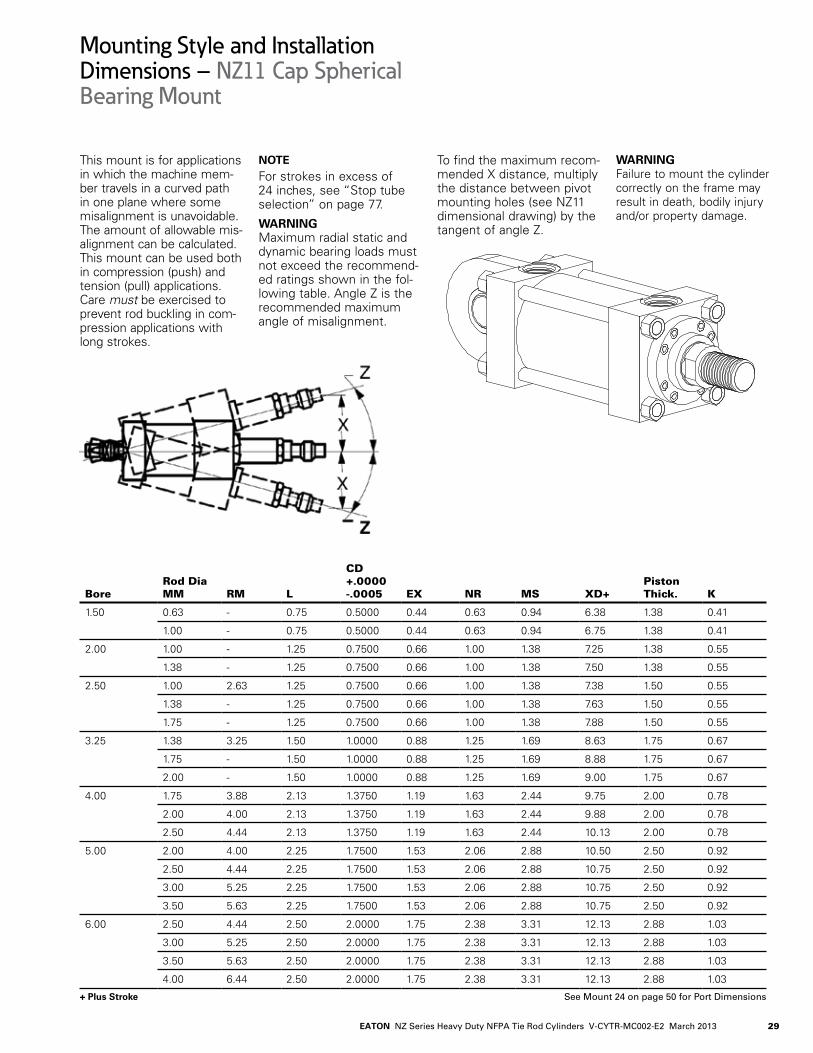
This mount is for applications in which the machine mem-ber travels in a curved path in one plane where some misalignment is unavoidable. The amount of allowable mis-alignment can be calculated. This mount can be used both in compression (push) and tension (pull) applications. Care must be exercised to prevent rod buckling in com-pression applications with long strokes.
NOTE For strokes in excess of 24. inches, see “Stop tube selection” on page 77.
WARNING Maximum radial static and dynamic bearing loads must not exceed the recommend-ed ratings shown in the fol-lowing table. Angle Z is the recommended maximum angle of misalignment.
To find the maximum recom-mended X distance, multiply the distance between pivot mounting holes (see NZ11 dimensional drawing) by the tangent of angle Z.
WARNING Failure to mount the cylinder correctly on the frame may result in death, bodily injury and/or property damage.
+ Plus Stroke
Mounting Style and InstallationDimensions – NZ11 Cap Spherical Bearing Mount
BoreRod Dia MM RM L
CD +.0000-.0005 EX NR MS XD+
Piston Thick. K
1.50 0.63 - 0.75 0.5000 0.4.4. 0.63 0.94. 6.38 1.38 0.4.1
1.00 - 0.75 0.5000 0.4.4. 0.63 0.94. 6.75 1.38 0.4.1
2.00 1.00 - 1.25 0.7500 0.66 1.00 1.38 7.25 1.38 0.55
1.38 - 1.25 0.7500 0.66 1.00 1.38 7.50 1.38 0.55
2.50 1.00 2.63 1.25 0.7500 0.66 1.00 1.38 7.38 1.50 0.55
1.38 - 1.25 0.7500 0.66 1.00 1.38 7.63 1.50 0.55
1.75 - 1.25 0.7500 0.66 1.00 1.38 7.88 1.50 0.55
3.25 1.38 3.25 1.50 1.0000 0.88 1.25 1.69 8.63 1.75 0.67
1.75 - 1.50 1.0000 0.88 1.25 1.69 8.88 1.75 0.67
2.00 - 1.50 1.0000 0.88 1.25 1.69 9.00 1.75 0.67
4..00 1.75 3.88 2.13 1.3750 1.19 1.63 2.4.4. 9.75 2.00 0.78
2.00 4..00 2.13 1.3750 1.19 1.63 2.4.4. 9.88 2.00 0.78
2.50 4..4.4. 2.13 1.3750 1.19 1.63 2.4.4. 10.13 2.00 0.78
5.00 2.00 4..00 2.25 1.7500 1.53 2.06 2.88 10.50 2.50 0.92
2.50 4..4.4. 2.25 1.7500 1.53 2.06 2.88 10.75 2.50 0.92
3.00 5.25 2.25 1.7500 1.53 2.06 2.88 10.75 2.50 0.92
3.50 5.63 2.25 1.7500 1.53 2.06 2.88 10.75 2.50 0.92
6.00 2.50 4..4.4. 2.50 2.0000 1.75 2.38 3.31 12.13 2.88 1.03
3.00 5.25 2.50 2.0000 1.75 2.38 3.31 12.13 2.88 1.03
3.50 5.63 2.50 2.0000 1.75 2.38 3.31 12.13 2.88 1.03
4..00 6.4.4. 2.50 2.0000 1.75 2.38 3.31 12.13 2.88 1.03
See Mount 24 on page 50 for Port Dimensions

EATON NZ Series Heavy Duty NFPA Tie Rod Cylinders V-CYTR-MC002-E2 March 201330
+ Plus Stroke
FP BOLT
1
UF
RM
2
3
E
TF
ER4
G
G1
MM
F J
STROKE+ZJ
STROKE+ZF
V
C
FH
B
K
Mounting Style and InstallationDimensions – NZ12 Cap Rectangular Flange Mount ANSI MF2
BoreRod Dia MM
B +.000/-.002 C E G J FH RM V F
1.50 0.63 1.124. 0.38 2.50 1.75 1.50 0.38 - 0.25 0.38
1.00 1.4.99 0.50 2.50 1.75 1.50 0.38 - 0.50 0.38
2.00 1.00 1.4.99 0.50 3.00 1.75 1.50 0.63 - 0.25 0.63
1.38 1.999 0.63 3.00 1.75 1.50 0.63 - 0.38 0.63
2.50 1.00 1.4.99 0.50 3.50 1.75 1.50 0.50 2.63 0.38 0.63
1.38 1.999 0.63 3.50 1.75 1.50 0.63 - 0.38 0.63
1.75 2.374. 0.75 3.50 1.75 1.50 0.63 - 0.50 0.63
3.25 1.38 1.999 0.63 4..50 2.00 1.75 0.59 3.25 0.4.1 0.75
1.75 2.374. 0.75 4..50 2.00 1.75 0.75 - 0.38 0.75
2.00 2.624. 0.88 4..50 2.00 1.75 0.75 - 0.38 0.75
4..00 1.75 2.374. 0.75 5.00 2.00 1.75 0.59 3.88 0.53 0.88
2.00 2.624. 0.88 5.00 2.00 1.75 0.59 4..00 0.53 0.88
2.50 3.124. 1.00 5.00 2.00 1.75 0.59 4..4.4. 0.66 0.88
5.00 2.00 2.624. 0.88 6.50 2.00 1.75 0.59 4..00 0.53 0.88
2.50 3.124. 1.00 6.50 2.00 1.75 0.59 4..4.4. 0.66 0.88
3.00 3.74.9 1.00 6.50 2.00 1.75 0.72 5.25 0.53 0.88
3.50 4..24.9 1.00 6.50 2.00 1.75 0.72 5.63 0.53 0.88
6.00 2.50 3.124. 1.00 7.50 2.25 2.25 0.59 4..4.4. 0.66 1.00
3.00 3.74.9 1.00 7.50 2.25 2.25 0.72 5.25 0.53 1.00
3.50 4..24.9 1.00 7.50 2.25 2.25 0.72 5.63 0.53 1.00
4..00 4..74.9 1.00 7.50 2.25 2.25 0.88 6.4.4. 0.38 1.00
7.00 3.00 3.74.9 1.00 8.50 2.75 2.75 0.72 5.25 0.53 1.00
3.50 4..24.9 1.00 8.50 2.75 2.75 0.72 5.63 0.53 1.00
4..00 4..74.9 1.00 8.50 2.75 2.75 0.88 6.4.4. 0.38 1.00
4..50 5.24.9 1.00 8.50 2.75 2.75 0.88 7.13 0.38 1.00
5.00 5.74.9 1.00 8.50 2.75 2.75 0.88 7.56 0.38 1.00
8.00 3.50 4..24.9 1.00 9.50 3.00 3.00 0.72 5.63 0.53 1.00
4..00 4..74.9 1.00 9.50 3.00 3.00 0.88 6.4.4. 0.38 1.00
4..50 5.24.9 1.00 9.50 3.00 3.00 0.88 7.13 0.38 1.00
5.00 5.74.9 1.00 9.50 3.00 3.00 0.88 7.56 0.38 1.00
5.50 6.24.9 1.00 9.50 3.00 3.00 0.88 8.38 0.38 1.00
For minimum flangedeflection see table next page.
FB

31EATON NZ Series Heavy Duty NFPA Tie Rod Cylinders V-CYTR-MC002-E2 March 2013
+ Plus Stroke
These mounts are ideal for straight line force transfer applications in which the cylinder is used in compres-sion (pushing), as in push presses.
For tension applications (pulling), a head rectangular mount is more appropriate.
NOTE For strokes in excess of 30 inches, see “Stop tube selection” on page 77.
WARNING The frame on which the cylinder is mounted must be sufficiently rigid to resist bending moments.
The cap rectangular mounts (NZ14.) is recommended for heavy duty applications. Refer to the table for recom-mended pressure ratings in pull stroke.
Use high tensile socket head cap screws or hex head bolts tightened to the manu-facturer’s recommended torque.
WARNING Failure to mount the cylinder correctly on the frame may result in death, bodily injury and/or property damage.
Mounting Style and InstallationDimensions – NZ12 Cap Rectangular Flange Mount ANSI MF2
BoreRod Dia MM FB R TF UF
ZF+ Max
ZJ+ Max
Piston Thick. K
1.50 0.63 0.38 1.63 3.4.4. 4..25 6.00 5.63 1.38 0.4.1
1.00 0.38 1.63 3.4.4. 4..25 6.38 6.00 1.38 0.4.1
2.00 1.00 0.50 2.05 4..13 5.13 6.63 6.00 1.38 0.55
1.38 0.50 2.05 4..13 5.13 6.88 6.26 1.38 0.55
2.50 1.00 0.50 2.55 4..63 5.63 6.75 6.13 1.50 0.55
1.38 0.50 2.55 4..63 5.63 7.00 6.38 1.50 0.55
1.75 0.50 2.55 4..63 5.63 7.25 6.63 1.50 0.55
3.25 1.38 0.63 3.25 5.88 7.13 7.88 7.13 1.75 0.67
1.75 0.63 3.25 5.88 7.13 8.13 7.38 1.75 0.67
2.00 0.63 3.25 5.88 7.13 8.25 7.50 1.75 0.67
4..00 1.75 0.63 3.82 6.38 7.63 8.50 7.63 2.00 0.78
2.00 0.63 3.82 6.38 7.63 8.63 7.75 2.00 0.78
2.50 0.63 3.82 6.38 7.63 8.88 8.00 2.00 0.78
5.00 2.00 0.88 4..95 8.19 9.75 9.13 8.25 2.50 0.92
2.50 0.88 4..95 8.19 9.75 9.38 8.50 2.50 0.92
3.00 0.88 4..95 8.19 9.75 9.38 8.50 2.50 0.92
3.50 0.88 4..95 8.19 9.75 9.38 8.50 2.50 0.92
6.00 2.50 1.00 5.73 9.4.4. 11.25 10.63 9.63 2.88 1.03
3.00 1.00 5.73 9.4.4. 11.25 10.63 9.63 2.88 1.03
3.50 1.00 5.73 9.4.4. 11.25 10.63 9.63 2.88 1.03
4..00 1.00 5.73 9.4.4. 11.25 10.63 9.63 2.88 1.03
7.00 3.00 1.13 6.58 10.63 12.63 11.75 10.75 3.00 1.17
3.50 1.13 6.58 10.63 12.63 11.75 10.75 3.00 1.17
4..00 1.13 6.58 10.63 12.63 11.75 10.75 3.00 1.17
4..50 1.13 6.58 10.63 12.63 11.75 10.75 3.00 1.17
5.00 1.13 6.58 10.63 12.63 11.75 10.75 3.00 1.17
8.00 3.50 1.25 7.50 11.81 14..00 12.75 11.75 3.50 1.26
4..00 1.25 7.50 11.81 14..00 12.75 11.75 3.50 1.26
4..50 1.25 7.50 11.81 14..00 12.75 11.75 3.50 1.26
5.00 1.25 7.50 11.81 14..00 12.75 11.75 3.50 1.26
5.50 1.25 7.50 11.81 14..00 12.75 11.75 3.50 1.26
See Mount 24 on page 50 for Port Dimensions
Recommended Pressure Rating Bore Size in Pull Stroke
1.50 to 4..00 3000 psi5.00 1800 psi6.00 1800 psi7.00 1300 psi8.00 1000 psi

EATON NZ Series Heavy Duty NFPA Tie Rod Cylinders V-CYTR-MC002-E2 March 201332
+ Plus Stroke
V
MM
C
2
B
K
4
JG
F
STROKE+ZJ
STROKE+ZF
FH
G1
1
3R
ER
RM
TF UF
UF
ETF
FB BOLT
Mounting Style and InstallationDimensions – Flange MountANSI MF6
BoreRod Dia MM
B +.000/-.002 C E G J FH RM V F
1.50 0.63 1.124. 0.38 2.50 1.75 1.50 0.38 - 0.25 0.38
1.00 1.4.99 0.50 2.50 1.75 1.50 0.38 - 0.50 0.38
2.00 1.00 1.4.99 0.50 3.00 1.75 1.50 0.63 - 0.25 0.63
1.38 1.999 0.63 3.00 1.75 1.50 0.63 - 0.38 0.63
2.50 1.00 1.4.99 0.50 3.50 1.75 1.50 0.50 2.63 0.38 0.63
1.38 1.999 0.63 3.50 1.75 1.50 0.63 - 0.38 0.63
1.75 2.374. 0.75 3.50 1.75 1.50 0.63 - 0.50 0.63
3.25 1.38 1.999 0.63 4..50 2.00 1.75 0.59 3.25 0.4.1 0.75
1.75 2.374. 0.75 4..50 2.00 1.75 0.75 - 0.38 0.75
2.00 2.624. 0.88 4..50 2.00 1.75 0.75 - 0.38 0.75
4..00 1.75 2.374. 0.75 5.00 2.00 1.75 0.59 3.88 0.53 0.88
2.00 2.624. 0.88 5.00 2.00 1.75 0.59 4..00 0.53 0.88
2.50 3.124. 1.00 5.00 2.00 1.75 0.59 4..4.4. 0.66 0.88
5.00 2.00 2.624. 0.88 6.50 2.00 1.75 0.59 4..00 0.53 0.88
2.50 3.124. 1.00 6.50 2.00 1.75 0.59 4..4.4. 0.66 0.88
3.00 3.74.9 1.00 6.50 2.00 1.75 0.72 5.25 0.53 0.88
3.50 4..24.9 1.00 6.50 2.00 1.75 0.72 5.63 0.53 0.88
6.00 2.50 3.124. 1.00 7.50 2.25 2.25 0.59 4..4.4. 0.66 1.00
3.00 3.74.9 1.00 7.50 2.25 2.25 0.72 5.25 0.53 1.00
3.50 4..24.9 1.00 7.50 2.25 2.25 0.72 5.63 0.53 1.00
4..00 4..74.9 1.00 7.50 2.25 2.25 0.88 6.4.4. 0.38 1.00
7.00 3.00 3.74.9 1.00 8.50 2.75 2.75 0.72 5.25 0.53 1.00
3.50 4..24.9 1.00 8.50 2.75 2.75 0.72 5.63 0.53 1.00
4..00 4..74.9 1.00 8.50 2.75 2.75 0.88 6.4.4. 0.38 1.00
4..50 5.24.9 1.00 8.50 2.75 2.75 0.88 7.13 0.38 1.00
5.00 5.74.9 1.00 8.50 2.75 2.75 0.88 7.56 0.38 1.00
8.00 3.50 4..24.9 1.00 9.50 3.00 3.00 0.72 5.63 0.53 1.00
4..00 4..74.9 1.00 9.50 3.00 3.00 0.88 6.4.4. 0.38 1.00
4..50 5.24.9 1.00 9.50 3.00 3.00 0.88 7.13 0.38 1.00
5.00 5.74.9 1.00 9.50 3.00 3.00 0.88 7.56 0.38 1.00
5.50 6.24.9 1.00 9.50 3.00 3.00 0.88 8.38 0.38 1.00
V
MM
C
2
B
K
4
JG
F
STROKE+ZJ
STROKE+ZF
FH
G1
1
3R
ER
RM
TF UF
UF
ETF
FB BOLT

33EATON NZ Series Heavy Duty NFPA Tie Rod Cylinders V-CYTR-MC002-E2 March 2013
+ Plus Stroke
These mounts are ideal for straight line force transfer applications in which the cylinder is used in compres-sion (pushing), as in push presses.
For tension applications (pulling), a head rectangular mount is more appropriate. NOTE For strokes in excess of 30 inches, see “Stop tube selec-tion” on page 77.
WARNING The frame on which the cylinder is mounted must be sufficiently rigid to resist bending moments.The cap rectangular mounts (NZ14.) is recommended for heavy duty applications.
Use high tensile socket head cap screws or hex head bolts tightened to the manufactur-er’s recommended torque.
WARNING Failure to mount the cylinder correctly on the frame may result in death, bodily injury and/or property damage.
Mounting Style and InstallationDimensions – NZ13 Cap Square Flange Mount ANSI MF6
BoreRod Dia MM FB R TF UF
ZF+ Max
ZJ+ Max
Piston Thick. K
1.50 0.63 0.38 1.63 3.4.4. 4..25 6.00 5.63 1.38 0.4.1
1.00 0.38 1.63 3.4.4. 4..25 6.38 6.00 1.38 0.4.1
2.00 1.00 0.50 2.05 4..13 5.13 6.63 6.00 1.38 0.55
1.38 0.50 2.05 4..13 5.13 6.88 6.26 1.38 0.55
2.50 1.00 0.50 2.55 4..63 5.63 6.75 6.13 1.50 0.55
1.38 0.50 2.55 4..63 5.63 7.00 6.38 1.50 0.55
1.75 0.50 2.55 4..63 5.63 7.25 6.63 1.50 0.55
3.25 1.38 0.63 3.25 5.88 7.13 7.88 7.13 1.75 0.67
1.75 0.63 3.25 5.88 7.13 8.13 7.38 1.75 0.67
2.00 0.63 3.25 5.88 7.13 8.25 7.50 1.75 0.67
4..00 1.75 0.63 3.82 6.38 7.63 8.50 7.63 2.00 0.78
2.00 0.63 3.82 6.38 7.63 8.63 7.75 2.00 0.78
2.50 0.63 3.82 6.38 7.63 8.88 8.00 2.00 0.78
5.00 2.00 0.88 4..95 8.19 9.75 9.13 8.25 2.50 0.92
2.50 0.88 4..95 8.19 9.75 9.38 8.50 2.50 0.92
3.00 0.88 4..95 8.19 9.75 9.38 8.50 2.50 0.92
3.50 0.88 4..95 8.19 9.75 9.38 8.50 2.50 0.92
6.00 2.50 1.00 5.73 9.4.4. 11.25 10.63 9.63 2.88 1.03
3.00 1.00 5.73 9.4.4. 11.25 10.63 9.63 2.88 1.03
3.50 1.00 5.73 9.4.4. 11.25 10.63 9.63 2.88 1.03
4..00 1.00 5.73 9.4.4. 11.25 10.63 9.63 2.88 1.03
7.00 3.00 1.13 6.58 10.63 12.63 11.75 10.75 3.00 1.17
3.50 1.13 6.58 10.63 12.63 11.75 10.75 3.00 1.17
4..00 1.13 6.58 10.63 12.63 11.75 10.75 3.00 1.17
4..50 1.13 6.58 10.63 12.63 11.75 10.75 3.00 1.17
5.00 1.13 6.58 10.63 12.63 11.75 10.75 3.00 1.17
8.00 3.50 1.25 7.50 11.81 14..00 12.75 11.75 3.50 1.26
4..00 1.25 7.50 11.81 14..00 12.75 11.75 3.50 1.26
4..50 1.25 7.50 11.81 14..00 12.75 11.75 3.50 1.26
5.00 1.25 7.50 11.81 14..00 12.75 11.75 3.50 1.26
5.50 1.25 7.50 11.81 14..00 12.75 11.75 3.50 1.26
See Mount 24 on page 50 for Port Dimensions

EATON NZ Series Heavy Duty NFPA Tie Rod Cylinders V-CYTR-MC002-E2 March 201334
+ Plus Stroke
CVF
B
G1G
MM
J
STROKE+ZJ
K
FB BOLT TF
RM
UF
E
R E
1
4
3
2
Mounting Style and InstallationDimensions – NZ14 Cap Rectangle Mount ANSI ME6
BoreRod Dia MM
B +.000/-.002 C E G J F V RM
1.50 0.63 1.124. 0.38 2.50 1.75 1.50 0.38 0.25 -
1.00 1.4.99 0.50 2.50 1.75 1.50 0.38 0.50 -
2.00 1.00 1.4.99 0.50 3.00 1.75 1.50 0.63 0.25 -
1.38 1.999 0.63 3.00 1.75 1.50 0.63 0.38 -
2.50 1.00 1.4.99 0.50 3.50 1.75 1.50 0.50 0.38 2.63
1.38 1.999 0.63 3.50 1.75 1.50 0.63 0.38 -
1.75 2.374. 0.75 3.50 1.75 1.50 0.63 0.50 -
3.25 1.38 1.999 0.63 4..50 2.00 1.75 0.59 0.4.1 3.25
1.75 2.374. 0.75 4..50 2.00 1.75 0.75 0.38 -
2.00 2.624. 0.88 4..50 2.00 1.75 0.75 0.38 -
4..00 1.75 2.374. 0.75 5.00 2.00 1.75 0.59 0.53 3.88
2.00 2.624. 0.88 5.00 2.00 1.75 0.59 0.53 4..00
2.50 3.124. 1.00 5.00 2.00 1.75 0.59 0.66 4..4.4.
5.00 2.00 2.624. 0.88 6.50 2.00 1.75 0.59 0.53 4..00
2.50 3.124. 1.00 6.50 2.00 1.75 0.59 0.66 4..4.4.
3.00 3.74.9 1.00 6.50 2.00 1.75 0.72 0.53 5.25
3.50 4..24.9 1.00 6.50 2.00 1.75 0.72 0.53 5.63
6.00 2.50 3.124. 1.00 7.50 2.25 2.25 0.59 0.66 4..4.4.
3.00 3.74.9 1.00 7.50 2.25 2.25 0.72 0.53 5.25
3.50 4..24.9 1.00 7.50 2.25 2.25 0.72 0.53 5.63
4..00 4..74.9 1.00 7.50 2.25 2.25 0.88 0.38 6.4.4.
7.00 3.00 3.74.9 1.00 8.50 2.75 2.75 0.72 0.53 5.25
3.50 4..24.9 1.00 8.50 2.75 2.75 0.72 0.53 5.63
4..00 4..74.9 1.00 8.50 2.75 2.75 0.88 0.38 6.4.4.
4..50 5.24.9 1.00 8.50 2.75 2.75 0.88 0.38 7.13
5.00 5.74.9 1.00 8.50 2.75 2.75 0.88 0.38 7.56
8.00 3.50 4..24.9 1.00 9.50 3.00 3.00 0.72 0.53 5.63
4..00 4..74.9 1.00 9.50 3.00 3.00 0.88 0.38 6.4.4.
4..50 5.24.9 1.00 9.50 3.00 3.00 0.88 0.38 7.13
5.00 5.74.9 1.00 9.50 3.00 3.00 0.88 0.38 7.56
5.50 6.24.9 1.00 9.50 3.00 3.00 0.88 0.38 8.38

35EATON NZ Series Heavy Duty NFPA Tie Rod Cylinders V-CYTR-MC002-E2 March 2013
+ Plus Stroke
These mounts are for straight line force transfer applications in which the cyl-inder is used in compression (pushing) and tension (pull-ing) applications.
The mounting surface should be flat and perpendicular to the force of the load.
The frame on which the cylinder is mounted must be sufficiently rigid to resist bending moments.
The cap rectangular mount (NZ14.) is recommended for heavy duty applications.
NOTE For strokes in excess of 30 inches, see “Stop tube selec-tion” on page 77.
WARNING Use high tensile socket head cap screws or hex head bolts tightened to the manufac-turer’s recommended torque value.
WARNING Failure to mount the cylinder correctly on the frame may result in death, bodily injury and/or property damage.
Mounting Style and InstallationDimensions – NZ14 Cap Rectangle Mount ANSI ME6
BoreRod Dia MM FB R TF UF
ZJ+ Max
Piston Thick. K
1.50 0.63 0.38 1.63 3.4.4. 4..25 5.63 1.38 0.4.1
1.00 0.38 1.63 3.4.4. 4..25 6.00 1.38 0.4.1
2.00 1.00 0.50 2.05 4..13 5.13 6.00 1.38 0.55
1.38 0.50 2.05 4..13 5.13 6.25 1.38 0.55
2.50 1.00 0.50 2.55 4..63 5.63 6.13 1.50 0.55
1.38 0.50 2.55 4..63 5.63 6.38 1.50 0.55
1.75 0.50 2.55 4..63 5.63 6.63 1.50 0.55
3.25 1.38 0.63 3.25 5.88 7.13 7.13 1.75 0.67
1.75 0.63 3.25 5.88 7.13 7.38 1.75 0.67
2.00 0.63 3.25 5.88 7.13 7.50 1.75 0.67
4..00 1.75 0.63 3.82 6.38 7.63 7.63 2.00 0.78
2.00 0.63 3.82 6.38 7.63 7.75 2.00 0.78
2.50 0.63 3.82 6.38 7.63 8.00 2.00 0.78
5.00 2.00 0.88 4..95 8.19 9.75 8.25 2.50 0.92
2.50 0.88 4..95 8.19 9.75 8.50 2.50 0.92
3.00 0.88 4..95 8.19 9.75 8.50 2.50 0.92
3.50 0.88 4..95 8.19 9.75 8.50 2.50 0.92
6.00 2.50 1.00 5.73 9.4.4. 11.25 9.63 2.88 1.03
3.00 1.00 5.73 9.4.4. 11.25 9.63 2.88 1.03
3.50 1.00 5.73 9.4.4. 11.25 9.63 2.88 1.03
4..00 1.00 5.73 9.4.4. 11.25 9.63 2.88 1.03
7.00 3.00 1.13 6.58 10.63 12.63 10.75 3.00 1.17
3.50 1.13 6.58 10.63 12.63 10.75 3.00 1.17
4..00 1.13 6.58 10.63 12.63 10.75 3.00 1.17
4..50 1.13 6.58 10.63 12.63 10.75 3.00 1.17
5.00 1.13 6.58 10.63 12.63 10.75 3.00 1.17
8.00 3.50 1.25 7.50 11.81 14..00 11.75 3.50 1.26
4..00 1.25 7.50 11.81 14..00 11.75 3.50 1.26
4..50 1.25 7.50 11.81 14..00 11.75 3.50 1.26
5.00 1.25 7.50 11.81 14..00 11.75 3.50 1.26
5.50 1.25 7.50 11.81 14..00 11.75 3.50 1.26
See Mount 24 on page 50 for Port Dimensions

EATON NZ Series Heavy Duty NFPA Tie Rod Cylinders V-CYTR-MC002-E2 March 201336
+ Plus Stroke
JK
XV
G1
GVF C
STROKE+ZB
TA
B
MM
2
RM
3
R .13/.06
UM
1
TM
TD O
TL TL
E4
Mounting Style and InstallationDimensions – NZ15 Intermediate Trunnion Mounts NFPA MT4 Mount
BoreRod DiaMM
B +.000/-.002 C E G J F V RM
TD +.000/-.001 TL
1.50 0.63 1.124. 0.38 2.50 1.75 1.50 0.38 0.25 - 1.000 1.00
1.00 1.4.99 0.50 2.50 1.75 1.50 0.38 0.50 - 1.000 1.00
2.00 1.00 1.4.99 0.50 3.00 1.75 1.50 0.63 0.25 - 1.375 1.38
1.38 1.999 0.63 3.00 1.75 1.50 0.63 0.38 - 1.375 1.38
2.50 1.00 1.4.99 0.50 3.50 1.75 1.50 0.50 0.38 2.63 1.375 1.38
1.38 1.999 0.63 3.50 1.75 1.50 0.63 0.38 - 1.375 1.38
1.75 2.374. 0.75 3.50 1.75 1.50 0.63 0.50 - 1.375 1.38
3.25 1.38 1.999 0.63 4..50 2.00 1.75 0.59 0.4.1 3.25 1.750 1.75
1.75 2.374. 0.75 4..50 2.00 1.75 0.75 0.38 - 1.750 1.75
2.00 2.624. 0.88 4..50 2.00 1.75 0.75 0.38 - 1.750 1.75
4..00 1.75 2.374. 0.75 5.00 2.00 1.75 0.59 0.53 3.88 1.750 1.75
2.00 2.624. 0.88 5.00 2.00 1.75 0.59 0.53 4..00 1.750 1.75
2.50 3.124. 1.00 5.00 2.00 1.75 0.59 0.66 4..4.4. 1.750 1.75
5.00 2.00 2.624. 0.88 6.50 2.00 1.75 0.59 0.53 4..00 1.750 1.75
2.50 3.124. 1.00 6.50 2.00 1.75 0.59 0.66 4..4.4. 1.750 1.75
3.00 3.74.9 1.00 6.50 2.00 1.75 0.72 0.53 5.25 1.750 1.75
3.50 4..24.9 1.00 6.50 2.00 1.75 0.72 0.53 5.63 1.750 1.75
6.00 2.50 3.124. 1.00 7.50 2.25 2.25 0.59 0.66 4..4.4. 2.000 2.00
3.00 3.74.9 1.00 7.50 2.25 2.25 0.72 0.53 5.25 2.000 2.00
3.50 4..24.9 1.00 7.50 2.25 2.25 0.72 0.53 5.63 2.000 2.00
4..00 4..74.9 1.00 7.50 2.25 2.25 0.88 0.38 6.4.4. 2.000 2.00
7.00 3.00 3.74.9 1.00 8.50 2.75 2.75 0.72 0.53 5.25 2.500 2.50
3.50 4..24.9 1.00 8.50 2.75 2.75 0.72 0.53 5.63 2.500 2.50
4..00 4..74.9 1.00 8.50 2.75 2.75 0.88 0.38 6.4.4. 2.500 2.50
4..50 5.24.9 1.00 8.50 2.75 2.75 0.88 0.38 7.13 2.500 2.50
5.00 5.74.9 1.00 8.50 2.75 2.75 0.88 0.38 7.56 2.500 2.50
8.00 3.50 4..24.9 1.00 9.50 3.00 3.00 0.72 0.53 5.63 3.000 3.00
4..00 4..74.9 1.00 9.50 3.00 3.00 0.88 0.38 6.4.4. 3.000 3.00
4..50 5.24.9 1.00 9.50 3.00 3.00 0.88 0.38 7.13 3.000 3.00
5.00 5.74.9 1.00 9.50 3.00 3.00 0.88 0.38 7.56 3.000 3.00
5.50 6.24.9 1.00 9.50 3.00 3.00 0.88 0.38 8.38 3.000 3.00

37EATON NZ Series Heavy Duty NFPA Tie Rod Cylinders V-CYTR-MC002-E2 March 2013
+ Plus Stroke*XV = XV std + 1/2 Stroke
The Intermediate Trunnion Mount is for longer stroke applications in which the machine member travels in a curved path in one plane.
On special orders, the trun-nion can be located any-where along the body.
This mount can be used both in compression (push) and tension (pull) applica-tions.
NOTEFor strokes in excess of 24. inches, see “Stop tube selec-tion” on page 77.
WARNING It is recommended that rigidly mounted pillow blocks with bearings at least as long as the trunnion pins be used. The pillow blocks should be installed as close to the shoulder of the trunnion as possible.
WARNING Failure to mount the cylinder correctly on the frame may result in death, bodily injury and/or property damage.
Mounting Style and InstallationDimensions – NZ15 Intermediate Trunnion Mounts NFPA MT4 Mount
BoreRod DiaMM UM TM TA
Max. O
XVStd *
ZB+ Max
Piston Thick. K
Minimum stroke Required
1.50 0.63 5.00 3.00 1.50 - 3.4.4. 6.04. 1.38 0.4.1 0.25
1.00 5.00 3.00 1.50 - 3.81 6.4.1 1.38 0.4.1 0.25
2.00 1.00 6.25 3.50 1.50 - 3.81 6.56 1.38 0.55 0.25
1.38 6.25 3.50 1.50 - 4..19 6.82 1.38 0.55 0.25
2.50 1.00 6.75 4..00 1.50 - 3.88 6.68 1.50 0.55 0.13
1.38 6.75 4..00 1.50 - 4..14. 6.94. 1.50 0.55 0.13
1.75 6.75 4..00 1.50 - 4..38 7.18 1.50 0.55 0.13
3.25 1.38 8.50 5.00 2.00 - 4..50 7.80 1.75 0.67 0.38
1.75 8.50 5.00 2.00 - 4..76 8.05 1.75 0.67 0.38
2.00 8.50 5.00 2.00 - 4..89 8.18 1.75 0.67 0.38
4..00 1.75 9.00 5.50 2.00 - 4..88 8.4.0 2.00 0.78 0.13
2.00 9.00 5.50 2.00 - 5.00 8.53 2.00 0.78 0.13
2.50 9.00 5.50 2.00 - 5.25 8.78 2.00 0.78 0.13
5.00 2.00 10.50 7.00 2.50 - 5.25 9.18 2.50 0.92 0.13
2.50 10.50 7.00 2.50 - 5.50 9.4.3 2.50 0.92 0.13
3.00 10.50 7.00 2.50 - 5.50 9.4.3 2.50 0.92 0.13
3.50 10.50 7.00 2.50 - 5.50 9.4.3 2.50 0.92 0.13
6.00 2.50 12.50 8.50 3.00 9.50 5.94. 10.66 2.88 1.03 0.25
3.00 12.50 8.50 3.00 9.50 5.94. 10.66 2.88 1.03 0.25
3.50 12.50 8.50 3.00 9.50 5.94. 10.66 2.88 1.03 0.25
4..00 12.50 8.50 3.00 9.50 5.94. 10.66 2.88 1.03 0.25
7.00 3.00 14..75 9.75 3.00 11.50 6.50 11.92 3.00 1.17 0.13
3.50 14..75 9.75 3.00 11.50 6.50 11.92 3.00 1.17 0.13
4..00 14..75 9.75 3.00 11.50 6.50 11.92 3.00 1.17 0.13
4..50 14..75 9.75 3.00 11.50 6.50 11.92 3.00 1.17 0.13
5.00 14..75 9.75 3.00 11.50 6.50 11.92 3.00 1.17 0.13
8.00 3.50 17.00 11.00 3.50 13.25 7.13 13.00 3.50 1.26 -
4..00 17.00 11.00 3.50 13.25 7.13 13.00 3.50 1.26 -
4..50 17.00 11.00 3.50 13.25 7.13 13.00 3.50 1.26 -
5.00 17.00 11.00 3.50 13.25 7.13 13.00 3.50 1.26 -
5.50 17.00 11.00 3.50 13.25 7.13 13.00 3.50 1.26 -
See Mount 24 on page 50 for Port Dimensions

EATON NZ Series Heavy Duty NFPA Tie Rod Cylinders V-CYTR-MC002-E2 March 201338
+ Plus Stroke
TC
4
TL
3
RM
E
TL
UT
TD
R .13/.06
1
2
CVF
XJ + STROKE
K J1 G
STROKE+ZB
MM
B
G1
Mounting Style and InstallationDimensions – NZ16 Trunnion Mounts NFPA MT2 Mount
TC
4
TL
3
RM
E
TL
UT
TD
R .13/.06
1
2
CVF
XJ + STROKE
K J1 G
STROKE+ZB
MM
B
G1
BoreRod Dia MM
B +.000/-.002 C E G J1 F V RM
1.50 0.63 1.124. 0.38 2.50 1.75 1.50 0.38 0.25 -
1.00 1.4.99 0.50 2.50 1.75 1.50 0.38 0.50 -
2.00 1.00 1.4.99 0.50 3.00 1.75 1.50 0.63 0.25 -
1.38 1.999 0.63 3.00 1.75 1.50 0.63 0.38 -
2.50 1.00 1.4.99 0.50 3.50 1.75 1.50 0.50 0.38 2.63
1.38 1.999 0.63 3.50 1.75 1.50 0.63 0.38 -
1.75 2.374. 0.75 3.50 1.75 1.50 0.63 0.50 -
3.25 1.38 1.999 0.63 4..50 2.00 1.75 0.59 0.4.1 3.25
1.75 2.374. 0.75 4..50 2.00 1.75 0.75 0.38 -
2.00 2.624. 0.88 4..50 2.00 1.75 0.75 0.38 -
4..00 1.75 2.374. 0.75 5.00 2.00 1.75 0.59 0.53 3.88
2.00 2.624. 0.88 5.00 2.00 1.75 0.59 0.53 4..00
2.50 3.124. 1.00 5.00 2.00 1.75 0.59 0.66 4..4.4.
5.00 2.00 2.624. 0.88 6.50 2.00 1.75 0.59 0.53 4..00
2.50 3.124. 1.00 6.50 2.00 1.75 0.59 0.66 4..4.4.
3.00 3.74.9 1.00 6.50 2.00 1.75 0.72 0.53 5.25
3.50 4..24.9 1.00 6.50 2.00 1.75 0.72 0.53 5.63
6.00 2.50 3.124. 1.00 7.50 2.25 2.25 0.59 0.66 4..4.4.
3.00 3.74.9 1.00 7.50 2.25 2.25 0.72 0.53 5.25
3.50 4..24.9 1.00 7.50 2.25 2.25 0.72 0.53 5.63
4..00 4..74.9 1.00 7.50 2.25 2.25 0.88 0.38 6.4.4.
7.00 3.00 3.74.9 1.00 8.50 2.75 2.75 0.72 0.53 5.25
3.50 4..24.9 1.00 8.50 2.75 2.75 0.72 0.53 5.63
4..00 4..74.9 1.00 8.50 2.75 2.75 0.88 0.38 6.4.4.
4..50 5.24.9 1.00 8.50 2.75 2.75 0.88 0.38 7.13
5.00 5.74.9 1.00 8.50 2.75 2.75 0.88 0.38 7.56
8.00 3.50 4..24.9 1.00 9.50 3.00 3.00 0.72 0.53 5.63
4..00 4..74.9 1.00 9.50 3.00 3.00 0.88 0.38 6.4.4.
4..50 5.24.9 1.00 9.50 3.00 3.00 0.88 0.38 7.13
5.00 5.74.9 1.00 9.50 3.00 3.00 0.88 0.38 7.56
5.50 6.24.9 1.00 9.50 3.00 3.00 0.88 0.38 8.38
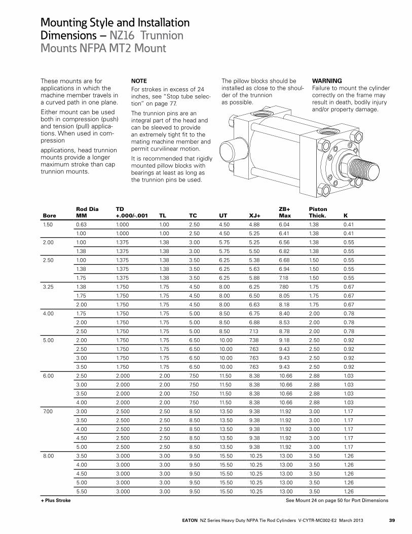
39EATON NZ Series Heavy Duty NFPA Tie Rod Cylinders V-CYTR-MC002-E2 March 2013
+ Plus Stroke
These mounts are for applications in which the machine member travels in a curved path in one plane.
Either mount can be used both in compression (push) and tension (pull) applica-tions. When used in com-pression
applications, head trunnion mounts provide a longer maximum stroke than cap trunnion mounts.
NOTE For strokes in excess of 24. inches, see “Stop tube selec-tion” on page 77.
The trunnion pins are an integral part of the head and can be sleeved to provide an extremely tight fit to the mating machine member and permit curvilinear motion.
It is recommended that rigidly mounted pillow blocks with bearings at least as long as the trunnion pins be used.
The pillow blocks should be installed as close to the shoul-der of the trunnion as possible.
WARNING Failure to mount the cylinder correctly on the frame may result in death, bodily injury and/or property damage.
Mounting Style and InstallationDimensions – NZ16 Trunnion Mounts NFPA MT2 Mount
BoreRod Dia MM
TD +.000/-.001 TL TC UT XJ+
ZB+ Max
Piston Thick. K
1.50 0.63 1.000 1.00 2.50 4..50 4..88 6.04. 1.38 0.4.1
1.00 1.000 1.00 2.50 4..50 5.25 6.4.1 1.38 0.4.1
2.00 1.00 1.375 1.38 3.00 5.75 5.25 6.56 1.38 0.55
1.38 1.375 1.38 3.00 5.75 5.50 6.82 1.38 0.55
2.50 1.00 1.375 1.38 3.50 6.25 5.38 6.68 1.50 0.55
1.38 1.375 1.38 3.50 6.25 5.63 6.94. 1.50 0.55
1.75 1.375 1.38 3.50 6.25 5.88 7.18 1.50 0.55
3.25 1.38 1.750 1.75 4..50 8.00 6.25 7.80 1.75 0.67
1.75 1.750 1.75 4..50 8.00 6.50 8.05 1.75 0.67
2.00 1.750 1.75 4..50 8.00 6.63 8.18 1.75 0.67
4..00 1.75 1.750 1.75 5.00 8.50 6.75 8.4.0 2.00 0.78
2.00 1.750 1.75 5.00 8.50 6.88 8.53 2.00 0.78
2.50 1.750 1.75 5.00 8.50 7.13 8.78 2.00 0.78
5.00 2.00 1.750 1.75 6.50 10.00 7.38 9.18 2.50 0.92
2.50 1.750 1.75 6.50 10.00 7.63 9.4.3 2.50 0.92
3.00 1.750 1.75 6.50 10.00 7.63 9.4.3 2.50 0.92
3.50 1.750 1.75 6.50 10.00 7.63 9.4.3 2.50 0.92
6.00 2.50 2.000 2.00 7.50 11.50 8.38 10.66 2.88 1.03
3.00 2.000 2.00 7.50 11.50 8.38 10.66 2.88 1.03
3.50 2.000 2.00 7.50 11.50 8.38 10.66 2.88 1.03
4..00 2.000 2.00 7.50 11.50 8.38 10.66 2.88 1.03
7.00 3.00 2.500 2.50 8.50 13.50 9.38 11.92 3.00 1.17
3.50 2.500 2.50 8.50 13.50 9.38 11.92 3.00 1.17
4..00 2.500 2.50 8.50 13.50 9.38 11.92 3.00 1.17
4..50 2.500 2.50 8.50 13.50 9.38 11.92 3.00 1.17
5.00 2.500 2.50 8.50 13.50 9.38 11.92 3.00 1.17
8.00 3.50 3.000 3.00 9.50 15.50 10.25 13.00 3.50 1.26
4..00 3.000 3.00 9.50 15.50 10.25 13.00 3.50 1.26
4..50 3.000 3.00 9.50 15.50 10.25 13.00 3.50 1.26
5.00 3.000 3.00 9.50 15.50 10.25 13.00 3.50 1.26
5.50 3.000 3.00 9.50 15.50 10.25 13.00 3.50 1.26
See Mount 24 on page 50 for Port Dimensions

EATON NZ Series Heavy Duty NFPA Tie Rod Cylinders V-CYTR-MC002-E2 March 201340
+ Plus Stroke
TD E
TCTL TL
UT
RM
R.013/.060
1
2
3
4
XXX
Drawn By:
XG
MM
J
STROKE+ZB
B
C
V
F
G1
GK
Mounting Style and InstallationDimensions – NZ17 Head Trunnion Mounts NFPA MT1 Mount
BoreRod Dia MM
B +.000/-.002 C E G J F V RM
1.50 0.63 1.124. 0.38 2.50 1.75 1.50 0.38 0.25 -
1.00 1.4.99 0.50 2.50 1.75 1.50 0.38 0.50 -
2.00 1.00 1.4.99 0.50 3.00 1.75 1.50 0.63 0.25 -
1.38 1.999 0.63 3.00 1.75 1.50 0.63 0.38 -
2.50 1.00 1.4.99 0.50 3.50 1.75 1.50 0.50 0.38 2.63
1.38 1.999 0.63 3.50 1.75 1.50 0.63 0.38 -
1.75 2.374. 0.75 3.50 1.75 1.50 0.63 0.50 -
3.25 1.38 1.999 0.63 4..50 2.00 1.75 0.59 0.4.1 3.25
1.75 2.374. 0.75 4..50 2.00 1.75 0.75 0.38 -
2.00 2.624. 0.88 4..50 2.00 1.75 0.75 0.38 -
4..00 1.75 2.374. 0.75 5.00 2.00 1.75 0.59 0.53 3.88
2.00 2.624. 0.88 5.00 2.00 1.75 0.59 0.53 4..00
2.50 3.124. 1.00 5.00 2.00 1.75 0.59 0.66 4..4.4.
5.00 2.00 2.624. 0.88 6.50 2.00 1.75 0.59 0.53 4..00
2.50 3.124. 1.00 6.50 2.00 1.75 0.59 0.66 4..4.4.
3.00 3.74.9 1.00 6.50 2.00 1.75 0.72 0.53 5.25
3.50 4..24.9 1.00 6.50 2.00 1.75 0.72 0.53 5.63
6.00 2.50 3.124. 1.00 7.50 2.25 2.25 0.59 0.66 4..4.4.
3.00 3.74.9 1.00 7.50 2.25 2.25 0.72 0.53 5.25
3.50 4..24.9 1.00 7.50 2.25 2.25 0.72 0.53 5.63
4..00 4..74.9 1.00 7.50 2.25 2.25 0.88 0.38 6.4.4.
7.00 3.00 3.74.9 1.00 8.50 2.75 2.75 0.72 0.53 5.25
3.50 4..24.9 1.00 8.50 2.75 2.75 0.72 0.53 5.63
4..00 4..74.9 1.00 8.50 2.75 2.75 0.88 0.38 6.4.4.
4..50 5.24.9 1.00 8.50 2.75 2.75 0.88 0.38 7.13
5.00 5.74.9 1.00 8.50 2.75 2.75 0.88 0.38 7.56
8.00 3.50 4..24.9 1.00 9.50 3.00 3.00 0.72 0.53 5.63
4..00 4..74.9 1.00 9.50 3.00 3.00 0.88 0.38 6.4.4.
4..50 5.24.9 1.00 9.50 3.00 3.00 0.88 0.38 7.13
5.00 5.74.9 1.00 9.50 3.00 3.00 0.88 0.38 7.56
5.50 6.24.9 1.00 9.50 3.00 3.00 0.88 0.38 8.38

41EATON NZ Series Heavy Duty NFPA Tie Rod Cylinders V-CYTR-MC002-E2 March 2013
+ Plus Stroke
These mounts are for applications in which the machine member travels in a curved path in one plane.
Either mount can be used both in compression (push) and tension (pull) applica-tions. When used in com-pression applications, head trunnion mounts provide a longer maximum stroke than cap trunnion mounts.
NOTE For strokes in excess of 24. inches, see “Stop tube selec-
tion” on page 77.
The trunnion pins are an integral part of the head and can be sleeved to provide an extremely tight fit to the mating machine member and permit curvilinear motion.
It is recommended that rigidly mounted pillow blocks with bearings at least as long as the trunnion pins be used. The pillow blocks should be installed as close to the shoulder of the trunnion as possible.
WARNING Failure to mount the cylinder correctly on the frame may result in death, bodily injury and/or property damage.
Mounting Style and InstallationDimensions – NZ17 Head Trunnion Mounts NFPA MT1 Mount
BoreRod Dia MM
TD +.000/-.001 TL TC UT XG+
ZB+ Max
Piston Thick. K
1.50 0.63 1.000 1.00 2.50 4..50 1.88 6.04. 1.38 0.4.1
1.00 1.000 1.00 2.50 4..50 2.25 6.4.1 1.38 0.4.1
2.00 1.00 1.375 1.38 3.00 5.75 2.25 6.56 1.38 0.55
1.38 1.375 1.38 3.00 5.75 2.50 6.82 1.38 0.55
2.50 1.00 1.375 1.38 3.50 6.25 2.25 6.68 1.50 0.55
1.38 1.375 1.38 3.50 6.25 2.50 6.94. 1.50 0.55
1.75 1.375 1.38 3.50 6.25 2.75 7.18 1.50 0.55
3.25 1.38 1.750 1.75 4..50 8.00 2.63 7.80 1.75 0.67
1.75 1.750 1.75 4..50 8.00 2.88 8.05 1.75 0.67
2.00 1.750 1.75 4..50 8.00 3.00 8.18 1.75 0.67
4..00 1.75 1.750 1.75 5.00 8.50 2.88 8.4.0 2.00 0.78
2.00 1.750 1.75 5.00 8.50 3.00 8.53 2.00 0.78
2.50 1.750 1.75 5.00 8.50 3.25 8.78 2.00 0.78
5.00 2.00 1.750 1.75 6.50 10.00 3.00 9.18 2.50 0.92
2.50 1.750 1.75 6.50 10.00 3.25 9.4.3 2.50 0.92
3.00 1.750 1.75 6.50 10.00 3.25 9.4.3 2.50 0.92
3.50 1.750 1.75 6.50 10.00 3.25 9.4.3 2.50 0.92
6.00 2.50 2.000 2.00 7.50 11.50 3.38 10.66 2.88 1.03
3.00 2.000 2.00 7.50 11.50 3.38 10.66 2.88 1.03
3.50 2.000 2.00 7.50 11.50 3.38 10.66 2.88 1.03
4..00 2.000 2.00 7.50 11.50 3.38 10.66 2.88 1.03
7.00 3.00 2.500 2.50 8.50 13.50 3.63 11.92 3.00 1.17
3.50 2.500 2.50 8.50 13.50 3.63 11.92 3.00 1.17
4..00 2.500 2.50 8.50 13.50 3.63 11.92 3.00 1.17
4..50 2.500 2.50 8.50 13.50 3.63 11.92 3.00 1.17
5.00 2.500 2.50 8.50 13.50 3.63 11.92 3.00 1.17
8.00 3.50 3.000 3.00 9.50 15.50 3.75 13.00 3.50 1.26
4..00 3.000 3.00 9.50 15.50 3.75 13.00 3.50 1.26
4..50 3.000 3.00 9.50 15.50 3.75 13.00 3.50 1.26
5.00 3.000 3.00 9.50 15.50 3.75 13.00 3.50 1.26
5.50 3.000 3.00 9.50 15.50 3.75 13.00 3.50 1.26
See Mount 24 on page 50 for Port Dimensions

EATON NZ Series Heavy Duty NFPA Tie Rod Cylinders V-CYTR-MC002-E2 March 201342
+ Plus Stroke
E/2
US
TS
E
ST
E
RM
SB BOLT
1
2
3
4
K
STROKE+ZB
SY SU SU SY
STROKE+SS XS
C
V
B
MM
FG
G1
J
XXX
Drawn By:
Mounting Style and InstallationDimensions – NZ19 Center Lug Mounts ANSI MS3
BoreRod Dia MM
B +.000/-.002 C E G J F V RM SB SS+
1.50 0.63 1.124. 0.38 2.50 1.75 1.50 0.38 0.25 - 0.38 3.88
1.00 1.4.99 0.50 2.50 1.75 1.50 0.38 0.50 - 0.38 3.88
2.00 1.00 1.4.99 0.50 3.00 1.75 1.50 0.63 0.25 - 0.50 3.63
1.38 1.999 0.63 3.00 1.75 1.50 0.63 0.38 - 0.50 3.63
2.50 1.00 1.4.99 0.50 3.50 1.75 1.50 0.50 0.38 2.63 0.75 3.38
1.38 1.999 0.63 3.50 1.75 1.50 0.63 0.38 - 0.75 3.38
1.75 2.374. 0.75 3.50 1.75 1.50 0.63 0.50 - 0.75 3.38
3.25 1.38 1.999 0.63 4..50 2.00 1.75 0.59 0.4.1 3.25 0.75 4..13
1.75 2.374. 0.75 4..50 2.00 1.75 0.75 0.38 - 0.75 4..13
2.00 2.624. 0.88 4..50 2.00 1.75 0.75 0.38 - 0.75 4..13
4..00 1.75 2.374. 0.75 5.00 2.00 1.75 0.59 0.53 3.88 1.00 4..00
2.00 2.624. 0.88 5.00 2.00 1.75 0.59 0.53 4..00 1.00 4..00
2.50 3.124. 1.00 5.00 2.00 1.75 0.59 0.66 4..4.4. 1.00 4..00
5.00 2.00 2.624. 0.88 6.50 2.00 1.75 0.59 0.53 4..00 1.00 4..50
2.50 3.124. 1.00 6.50 2.00 1.75 0.59 0.66 4..4.4. 1.00 4..50
3.00 3.74.9 1.00 6.50 2.00 1.75 0.72 0.53 5.25 1.00 4..50
3.50 4..24.9 1.00 6.50 2.00 1.75 0.72 0.53 5.63 1.00 4..50
6.00 2.50 3.124. 1.00 7.50 2.25 2.25 0.59 0.66 4..4.4. 1.25 5.13
3.00 3.74.9 1.00 7.50 2.25 2.25 0.72 0.53 5.25 1.25 5.13
3.50 4..24.9 1.00 7.50 2.25 2.25 0.72 0.53 5.63 1.25 5.13
4..00 4..74.9 1.00 7.50 2.25 2.25 0.88 0.38 6.4.4. 1.25 5.13
7.00 3.00 3.74.9 1.00 8.50 2.75 2.75 0.72 0.53 5.25 1.50 5.75
3.50 4..24.9 1.00 8.50 2.75 2.75 0.72 0.53 5.63 1.50 5.75
4..00 4..74.9 1.00 8.50 2.75 2.75 0.88 0.38 6.4.4. 1.50 5.75
4..50 5.24.9 1.00 8.50 2.75 2.75 0.88 0.38 7.13 1.50 5.75
5.00 5.74.9 1.00 8.50 2.75 2.75 0.88 0.38 7.56 1.50 5.75
8.00 3.50 4..24.9 1.00 9.50 3.00 3.00 0.72 0.53 5.63 1.50 6.75
4..00 4..74.9 1.00 9.50 3.00 3.00 0.88 0.38 6.4.4. 1.50 6.75
4..50 5.24.9 1.00 9.50 3.00 3.00 0.88 0.38 7.13 1.50 6.75
5.00 5.74.9 1.00 9.50 3.00 3.00 0.88 0.38 7.56 1.50 6.75
5.50 6.24.9 1.00 9.50 3.00 3.00 0.88 0.38 8.38 1.50 6.75

43EATON NZ Series Heavy Duty NFPA Tie Rod Cylinders V-CYTR-MC002-E2 March 2013
+ Plus Stroke
Centerline lug mounts are for moving loads along a flat guided surface as in a car-riage along rails.
The mounting surface should be flat and parallel to the cen-terline of the piston rod.
The load should be guided to traverse along the center-line of the piston rod.
The frame on which the cylinder is mounted must be sufficiently rigid to resist bending moments.
NOTE Limit operating pressure to 1500 psi for minimum deflection. For strokes in excess of 30 inches, see “Stop tube selection” on page 77.
WARNING With unsupported loads, the bearing must absorb more force. For these applications, the larger available rod is recommended, and stop tubes should be considered.
Use high tensile socket head cap screws or hex head bolts tightened to the manufactur-er’s recommended torque.
For high shock applications, dowel pins or shear keys should be incorporated in the mounting design.
For severe side load applica-tions, consult your local Eaton sales engineer.
WARNING Failure to mount the cylinder correctly on the frame may result in death, bodily injury and/or property damage.
Mounting Style and InstallationDimensions – NZ19 Center Lug Mounts ANSI MS3
BoreRod Dia MM ST SU SY TS US XS
ZB+ Max
Piston Thick. K
1.50 0.63 0.50 0.91 0.38 3.25 4..00 1.38 6.04. 1.38 0.4.1
1.00 0.50 0.91 0.38 3.25 4..00 1.75 6.4.1 1.38 0.4.1
2.00 1.00 0.75 1.24. 0.50 4..00 5.00 1.88 6.56 1.38 0.55
1.38 0.75 1.24. 0.50 4..00 5.00 2.13 6.82 1.38 0.55
2.50 1.00 1.00 1.56 0.69 4..88 6.25 2.06 6.68 1.50 0.55
1.38 1.00 1.56 0.69 4..88 6.25 2.31 6.94. 1.50 0.55
1.75 1.00 1.56 0.69 4..88 6.25 2.56 7.18 1.50 0.55
3.25 1.38 1.00 1.55 0.69 5.88 7.25 2.31 7.80 1.75 0.67
1.75 1.00 1.55 0.69 5.88 7.25 2.56 8.05 1.75 0.67
2.00 1.00 1.55 0.69 5.88 7.25 2.69 8.18 1.75 0.67
4..00 1.75 1.25 2.00 0.88 6.75 8.50 2.75 8.4.0 2.00 0.78
2.00 1.25 2.00 0.88 6.75 8.50 2.88 8.53 2.00 0.78
2.50 1.25 2.00 0.88 6.75 8.50 3.13 8.78 2.00 0.78
5.00 2.00 1.25 2.00 0.88 8.25 10.00 2.88 9.18 2.50 0.92
2.50 1.25 2.00 0.88 8.25 10.00 3.13 9.4.3 2.50 0.92
3.00 1.25 2.00 0.88 8.25 10.00 3.13 9.4.3 2.50 0.92
3.50 1.25 2.00 0.88 8.25 10.00 3.13 9.4.3 2.50 0.92
6.00 2.50 1.50 2.50 1.13 9.75 12.00 3.38 10.66 2.88 1.03
3.00 1.50 2.50 1.13 9.75 12.00 3.38 10.66 2.88 1.03
3.50 1.50 2.50 1.13 9.75 12.00 3.38 10.66 2.88 1.03
4..00 1.50 2.50 1.13 9.75 12.00 3.38 10.66 2.88 1.03
7.00 3.00 1.75 2.88 1.38 11.25 14..00 3.63 11.92 3.00 1.17
3.50 1.75 2.88 1.38 11.25 14..00 3.63 11.92 3.00 1.17
4..00 1.75 2.88 1.38 11.25 14..00 3.63 11.92 3.00 1.17
4..50 1.75 2.88 1.38 11.25 14..00 3.63 11.92 3.00 1.17
5.00 1.75 2.88 1.38 11.25 14..00 3.63 11.92 3.00 1.17
8.00 3.50 1.75 2.88 1.38 12.25 15.00 3.63 13.00 3.50 1.26
4..00 1.75 2.88 1.38 12.25 15.00 3.63 13.00 3.50 1.26
4..50 1.75 2.88 1.38 12.25 15.00 3.63 13.00 3.50 1.26
5.00 1.75 2.88 1.38 12.25 15.00 3.63 13.00 3.50 1.26
5.50 1.75 2.88 1.38 12.25 15.00 3.63 13.00 3.50 1.26
See Mount 24 on page 50 for Port Dimensions

EATON NZ Series Heavy Duty NFPA Tie Rod Cylinders V-CYTR-MC002-E2 March 201344
+ Plus Stroke
AAG1
MM
J G
H
AC
BB
STROKE+ZJ
B
V
CF
(Typ. 4 )DD
R E
E
R
RM1
2
3
4
Mounting Style and InstallationDimensions – NZ21 Cap End Extended Tie Rod Mounts NFPA MX2 Mount
BoreRod Dia MM
B +.000/-.002 C E G J F V RM
1.50 0.63 1.124. 0.38 2.50 1.75 1.50 0.38 0.25 -
1.00 1.4.99 0.50 2.50 1.75 1.50 0.38 0.50 -
2.00 1.00 1.4.99 0.50 3.00 1.75 1.50 0.63 0.25 -
1.38 1.999 0.63 3.00 1.75 1.50 0.63 0.38 -
2.50 1.00 1.4.99 0.50 3.50 1.75 1.50 0.50 0.38 2.63
1.38 1.999 0.63 3.50 1.75 1.50 0.63 0.38 -
1.75 2.374. 0.75 3.50 1.75 1.50 0.63 0.50 -
3.25 1.38 1.999 0.63 4..50 2.00 1.75 0.59 0.4.1 3.25
1.75 2.374. 0.75 4..50 2.00 1.75 0.75 0.38 -
2.00 2.624. 0.88 4..50 2.00 1.75 0.75 0.38 -
4..00 1.75 2.374. 0.75 5.00 2.00 1.75 0.59 0.53 3.88
2.00 2.624. 0.88 5.00 2.00 1.75 0.59 0.53 4..00
2.50 3.124. 1.00 5.00 2.00 1.75 0.59 0.66 4..4.4.
5.00 2.00 2.624. 0.88 6.50 2.00 1.75 0.59 0.53 4..00
2.50 3.124. 1.00 6.50 2.00 1.75 0.59 0.66 4..4.4.
3.00 3.74.9 1.00 6.50 2.00 1.75 0.72 0.53 5.25
3.50 4..24.9 1.00 6.50 2.00 1.75 0.72 0.53 5.63
6.00 2.50 3.124. 1.00 7.50 2.25 2.25 0.59 0.66 4..4.4.
3.00 3.74.9 1.00 7.50 2.25 2.25 0.72 0.53 5.25
3.50 4..24.9 1.00 7.50 2.25 2.25 0.72 0.53 5.63
4..00 4..74.9 1.00 7.50 2.25 2.25 0.88 0.38 6.4.4.
7.00 3.00 3.74.9 1.00 8.50 2.75 2.75 0.72 0.53 5.25
3.50 4..24.9 1.00 8.50 2.75 2.75 0.72 0.53 5.63
4..00 4..74.9 1.00 8.50 2.75 2.75 0.88 0.38 6.4.4.
4..50 5.24.9 1.00 8.50 2.75 2.75 0.88 0.38 7.13
5.00 5.74.9 1.00 8.50 2.75 2.75 0.88 0.38 7.56
8.00 3.50 4..24.9 1.00 9.50 3.00 3.00 0.72 0.53 5.63
4..00 4..74.9 1.00 9.50 3.00 3.00 0.88 0.38 6.4.4.
4..50 5.24.9 1.00 9.50 3.00 3.00 0.88 0.38 7.13
5.00 5.74.9 1.00 9.50 3.00 3.00 0.88 0.38 7.56
5.50 6.24.9 1.00 9.50 3.00 3.00 0.88 0.38 8.38

45EATON NZ Series Heavy Duty NFPA Tie Rod Cylinders V-CYTR-MC002-E2 March 2013
+ Plus Stroke
These mounts are for straight line force transfer applications. The cap extend-ed tie rod mount is recom-mended for compression (pushing) applications.
The mounting surface should be flat and the frame on which the cylinder is mount-ed must be sufficiently rigid to resist bending moments.
Once fitted into the applica-tion framework, tmounting nuts should be torqued to the values listed in the table (right).
Tie Rod Torque ValuesTorque values in the follow-ing table apply to all mount-ing styles.
NOTE For strokes in excess of 30 inches, see “Stop tube selection” on page 77.
WARNING Failure to mount the cylinder correctly on the frame may result in death, bodily injury and/or property damage.
Mounting Style and InstallationDimensions – NZ21 Cap End Extended Tie Rod Mounts NFPA MX2 Mount
BoreRod Dia MM R AA
Max AC BB
(UN) DD ZJ+
Piston Thick.
Max H
1.50 0.63 1.63 2.30 0.69 1.38 .375-24. 5.63 1.38 0.38
1.00 1.63 2.30 0.69 1.38 .375-24. 6.00 1.38 0.38
2.00 1.00 2.05 2.90 0.88 1.81 .500-20 6.00 1.38 0.50
1.38 2.05 2.90 0.88 1.81 .500-20 6.26 1.38 0.50
2.50 1.00 2.55 3.60 0.88 1.81 .500-20 6.13 1.50 0.50
1.38 2.55 3.60 0.88 1.81 .500-20 6.38 1.50 0.50
1.75 2.55 3.60 0.88 1.81 .500-20 6.63 1.50 0.50
3.25 1.38 3.25 4..60 1.12 2.31 .625-18 7.13 1.75 0.63
1.75 3.25 4..60 1.12 2.31 .625-18 7.38 1.75 0.63
2.00 3.25 4..60 1.12 2.31 .625-18 7.51 1.75 0.63
4..00 1.75 3.82 5.4.0 1.12 2.31 .625-18 7.63 2.00 0.63
2.00 3.82 5.4.0 1.12 2.31 .625-18 7.75 2.00 0.63
2.50 3.82 5.4.0 1.12 2.31 .625-18 8.00 2.00 0.63
5.00 2.00 4..95 7.00 1.56 3.19 .875-14. 8.26 2.50 0.81
2.50 4..95 7.00 1.56 3.19 .875-14. 8.50 2.50 0.81
3.00 4..95 7.00 1.56 3.19 .875-14. 8.50 2.50 0.81
3.50 4..95 7.00 1.56 3.19 .875-14. 8.50 2.50 0.81
6.00 2.50 5.73 8.10 1.75 3.63 1.000-14. 9.63 2.88 0.94.
3.00 5.73 8.10 1.75 3.63 1.000-14. 9.63 2.88 0.94.
3.50 5.73 8.10 1.75 3.63 1.000-14. 9.63 2.88 0.94.
4..00 5.73 8.10 1.75 3.63 1.000-14. 9.63 2.88 0.94.
7.00 3.00 6.58 9.30 2.00 4..13 1.125-12 10.75 3.00 1.06
3.50 6.58 9.30 2.00 4..13 1.125-12 10.75 3.00 1.06
4..00 6.58 9.30 2.00 4..13 1.125-12 10.75 3.00 1.06
4..50 6.58 9.30 2.00 4..13 1.125-12 10.75 3.00 1.06
5.00 6.58 9.30 2.00 4..13 1.125-12 10.75 3.00 1.06
8.00 3.50 7.50 10.60 2.19 4..50 1.250-12 11.75 3.50 1.12
4..00 7.50 10.60 2.19 4..50 1.250-12 11.75 3.50 1.12
4..50 7.50 10.60 2.19 4..50 1.250-12 11.75 3.50 1.12
5.00 7.50 10.60 2.19 4..50 1.250-12 11.75 3.50 1.12
5.50 7.50 10.60 2.19 4..50 1.250-12 11.75 3.50 1.12
See Mount 24 on page 50 for Port Dimensions
Tie Rod TorqueBore Ft-Lb Nm1.50 30 4.1 2.00 4.0 54. 2.50 80 1083.25 190 2584..00 190 2585.00 550 74.6 6.00 700 94.97.00 750 10178.00 1250 1695

EATON NZ Series Heavy Duty NFPA Tie Rod Cylinders V-CYTR-MC002-E2 March 201346
+ Plus Stroke
AA
E
R E
R
RM1
2
3
3
H
J
STROKE+ZB
MM
CV
B
GFH
G1 W
K
BB
DD(Typ. 4)
AC
Mounting Style and InstallationDimensions – NZ22 Head End Extended Tie Rod Mounts NFPA MX3 Mount
BoreRod Dia MM
B +.000/-.002 C E G J FH V R
1.50 0.63 1.124. 0.38 2.50 1.75 1.50 0.38 0.25 1.63
1.00 1.4.99 0.50 2.50 1.75 1.50 0.38 0.50 1.63
2.00 1.00 1.4.99 0.50 3.00 1.75 1.50 0.63 0.25 2.05
1.38 1.999 0.63 3.00 1.75 1.50 0.63 0.38 2.05
2.50 1.00 1.4.99 0.50 3.50 1.75 1.50 0.63 0.25 2.55
1.38 1.999 0.63 3.50 1.75 1.50 0.63 0.38 2.55
1.75 2.374. 0.75 3.50 1.75 1.50 0.63 0.50 2.55
3.25 1.38 1.999 0.63 4..50 2.00 1.75 0.75 0.25 3.25
1.75 2.374. 0.75 4..50 2.00 1.75 0.75 0.38 3.25
2.00 2.624. 0.88 4..50 2.00 1.75 0.75 0.38 3.25
4..00 1.75 2.374. 0.75 5.00 2.00 1.75 0.88 0.25 3.82
2.00 2.624. 0.88 5.00 2.00 1.75 0.88 0.25 3.82
2.50 3.124. 1.00 5.00 2.00 1.75 0.88 0.38 3.82
5.00 2.00 2.624. 0.88 6.50 2.00 1.75 0.88 0.25 4..95
2.50 3.124. 1.00 6.50 2.00 1.75 0.88 0.38 4..95
3.00 3.74.9 1.00 6.50 2.00 1.75 0.88 0.38 4..95
3.50 4..24.9 1.00 6.50 2.00 1.75 0.88 0.38 4..95
6.00 2.50 3.124. 1.00 7.50 2.25 2.25 1.00 0.25 5.73
3.00 3.74.9 1.00 7.50 2.25 2.25 1.00 0.25 5.73
3.50 4..24.9 1.00 7.50 2.25 2.25 1.00 0.25 5.73
4..00 4..74.9 1.00 7.50 2.25 2.25 1.00 0.25 5.73
7.00 3.00 3.74.9 1.00 8.50 2.75 2.75 1.00 0.25 6.58
3.50 4..24.9 1.00 8.50 2.75 2.75 1.00 0.25 6.58
4..00 4..74.9 1.00 8.50 2.75 2.75 1.00 0.25 6.58
4..50 5.24.9 1.00 8.50 2.75 2.75 1.00 0.25 6.58
5.00 5.74.9 1.00 8.50 2.75 2.75 1.00 0.25 6.58
8.00 3.50 4..24.9 1.00 9.50 3.00 3.00 1.00 0.25 7.50
4..00 4..74.9 1.00 9.50 3.00 3.00 1.00 0.25 7.50
4..50 5.24.9 1.00 9.50 3.00 3.00 1.00 0.25 7.50
5.00 5.74.9 1.00 9.50 3.00 3.00 1.00 0.25 7.50
5.50 6.24.9 1.00 9.50 3.00 3.00 1.00 0.25 7.50
AA
E
R E
R
RM1
2
3
3
H
J
STROKE+ZB
MM
CV
B
GFH
G1 W
K
BB
DD(Typ. 4)
AC

47EATON NZ Series Heavy Duty NFPA Tie Rod Cylinders V-CYTR-MC002-E2 March 2013
+ Plus Stroke
These mounts are for straight line force trans-fer applications.The head extended tie rod mount is recommended for tension (pulling) applications.
The mounting surface should be flat and the frame on which the cylinder is mount-ed must be sufficiently rigid to resist bending moments.
On head mount applications, the cartridge provides a pilot diameter to align the rod in the mounting frame.
Once fitted into the applica-tion framework, mounting nuts should be torqued to the values listed in the table on page 4.5.
NOTE
For strokes in excess of 30 inches, see “Stop tube selec-tion” on page 77.
WARNING The force on the rod should be perpendicular to the mounting surface and coin-cide with the centerline of the piston rod. For eccentric
loads, the larger of the two available rods in each bore size is recommended. Stop tubes should also be consid-ered.
WARNING Failure to mount the cylinder correctly on the frame may result in death, bodily injury and/or property damage.
Mounting Style and InstallationDimensions – NZ22 Head End Extended Tie Rod Mounts NFPA MX3 Mount
BoreRod Dia MM AA
Max AC BB
(UN) DD
Max H
ZB+ Max
Piston Thick. K
1.50 0.63 2.30 0.69 1.38 .375-24. 0.34. 6.04. 1.38 0.4.1
1.00 2.30 0.69 1.38 .375-24. 0.34. 6.4.1 1.38 0.4.1
2.00 1.00 2.90 0.88 1.81 .500-20 0.4.5 6.56 1.38 0.55
1.38 2.90 0.88 1.81 .500-20 0.4.5 6.82 1.38 0.55
2.50 1.00 3.60 0.88 1.81 .500-20 0.4.5 6.68 1.50 0.55
1.38 3.60 0.88 1.81 .500-20 0.4.5 6.94. 1.50 0.55
1.75 3.60 0.88 1.81 .500-20 0.4.5 7.18 1.50 0.55
3.25 1.38 4..60 1.12 2.31 .625-18 0.56 7.80 1.75 0.67
1.75 4..60 1.12 2.31 .625-18 0.56 8.05 1.75 0.67
2.00 4..60 1.12 2.31 .625-18 0.56 8.18 1.75 0.67
4..00 1.75 5.4.0 1.12 2.31 .625-18 0.56 8.4.0 2.00 0.78
2.00 5.4.0 1.12 2.31 .625-18 0.56 8.53 2.00 0.78
2.50 5.4.0 1.12 2.31 .625-18 0.56 8.78 2.00 0.78
5.00 2.00 7.00 1.56 3.19 .875-14. 0.78 9.18 2.50 0.92
2.50 7.00 1.56 3.19 .875-14. 0.78 9.4.3 2.50 0.92
3.00 7.00 1.56 3.19 .875-14. 0.78 9.4.3 2.50 0.92
3.50 7.00 1.56 3.19 .875-14. 0.78 9.4.3 2.50 0.92
6.00 2.50 8.10 1.75 3.63 1.000-14. 0.89 10.66 2.88 1.03
3.00 8.10 1.75 3.63 1.000-14. 0.89 10.66 2.88 1.03
3.50 8.10 1.75 3.63 1.000-14. 0.89 10.66 2.88 1.03
4..00 8.10 1.75 3.63 1.000-14. 0.89 10.66 2.88 1.03
7.00 3.00 9.30 2.00 4..13 1.125-12 1.00 11.92 3.00 1.17
3.50 9.30 2.00 4..13 1.125-12 1.00 11.92 3.00 1.17
4..00 9.30 2.00 4..13 1.125-12 1.00 11.92 3.00 1.17
4..50 9.30 2.00 4..13 1.125-12 1.00 11.92 3.00 1.17
5.00 9.30 2.00 4..13 1.125-12 1.00 11.92 3.00 1.17
8.00 3.50 10.60 2.19 4..50 1.250-12 1.09 13.00 3.50 1.26
4..00 10.60 2.19 4..50 1.250-12 1.09 13.00 3.50 1.26
4..50 10.60 2.19 4..50 1.250-12 1.09 13.00 3.50 1.26
5.00 10.60 2.19 4..50 1.250-12 1.09 13.00 3.50 1.26
5.50 10.60 2.19 4..50 1.250-12 1.09 13.00 3.50 1.26
See Mount 24 on page 50 for Port Dimensions
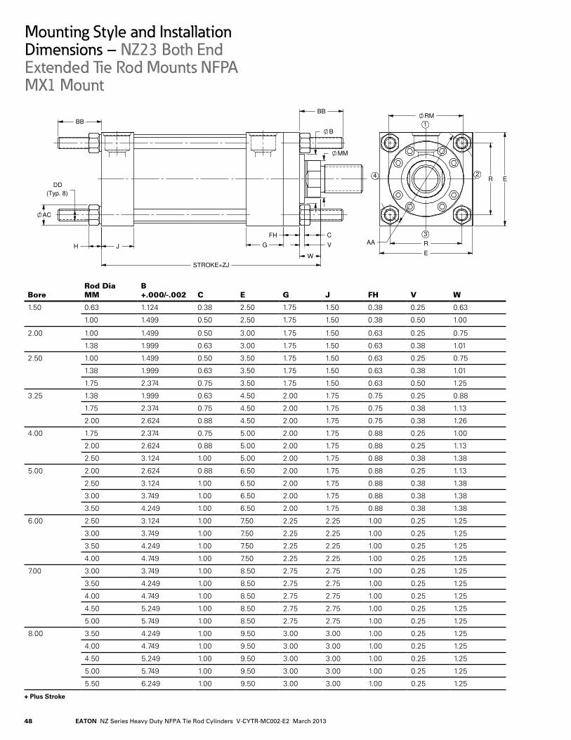
EATON NZ Series Heavy Duty NFPA Tie Rod Cylinders V-CYTR-MC002-E2 March 201348
+ Plus Stroke
AA
Drawn By:
E
R
E
R
RM
4
3
2
1
BB
MM
W
JH
AC
STROKE+ZJ
B
FH
BB
G
C
V
(Typ. 8)DD
XXXProcess Specifications and Review for Classification of
Mounting Style and InstallationDimensions – NZ23 Both End Extended Tie Rod Mounts NFPA MX1 Mount
BoreRod Dia MM
B +.000/-.002 C E G J FH V W
1.50 0.63 1.124. 0.38 2.50 1.75 1.50 0.38 0.25 0.63
1.00 1.4.99 0.50 2.50 1.75 1.50 0.38 0.50 1.00
2.00 1.00 1.4.99 0.50 3.00 1.75 1.50 0.63 0.25 0.75
1.38 1.999 0.63 3.00 1.75 1.50 0.63 0.38 1.01
2.50 1.00 1.4.99 0.50 3.50 1.75 1.50 0.63 0.25 0.75
1.38 1.999 0.63 3.50 1.75 1.50 0.63 0.38 1.01
1.75 2.374. 0.75 3.50 1.75 1.50 0.63 0.50 1.25
3.25 1.38 1.999 0.63 4..50 2.00 1.75 0.75 0.25 0.88
1.75 2.374. 0.75 4..50 2.00 1.75 0.75 0.38 1.13
2.00 2.624. 0.88 4..50 2.00 1.75 0.75 0.38 1.26
4..00 1.75 2.374. 0.75 5.00 2.00 1.75 0.88 0.25 1.00
2.00 2.624. 0.88 5.00 2.00 1.75 0.88 0.25 1.13
2.50 3.124. 1.00 5.00 2.00 1.75 0.88 0.38 1.38
5.00 2.00 2.624. 0.88 6.50 2.00 1.75 0.88 0.25 1.13
2.50 3.124. 1.00 6.50 2.00 1.75 0.88 0.38 1.38
3.00 3.74.9 1.00 6.50 2.00 1.75 0.88 0.38 1.38
3.50 4..24.9 1.00 6.50 2.00 1.75 0.88 0.38 1.38
6.00 2.50 3.124. 1.00 7.50 2.25 2.25 1.00 0.25 1.25
3.00 3.74.9 1.00 7.50 2.25 2.25 1.00 0.25 1.25
3.50 4..24.9 1.00 7.50 2.25 2.25 1.00 0.25 1.25
4..00 4..74.9 1.00 7.50 2.25 2.25 1.00 0.25 1.25
7.00 3.00 3.74.9 1.00 8.50 2.75 2.75 1.00 0.25 1.25
3.50 4..24.9 1.00 8.50 2.75 2.75 1.00 0.25 1.25
4..00 4..74.9 1.00 8.50 2.75 2.75 1.00 0.25 1.25
4..50 5.24.9 1.00 8.50 2.75 2.75 1.00 0.25 1.25
5.00 5.74.9 1.00 8.50 2.75 2.75 1.00 0.25 1.25
8.00 3.50 4..24.9 1.00 9.50 3.00 3.00 1.00 0.25 1.25
4..00 4..74.9 1.00 9.50 3.00 3.00 1.00 0.25 1.25
4..50 5.24.9 1.00 9.50 3.00 3.00 1.00 0.25 1.25
5.00 5.74.9 1.00 9.50 3.00 3.00 1.00 0.25 1.25
5.50 6.24.9 1.00 9.50 3.00 3.00 1.00 0.25 1.25

49EATON NZ Series Heavy Duty NFPA Tie Rod Cylinders V-CYTR-MC002-E2 March 2013
+ Plus Stroke
These mounts are for straight line force transfer applications. Both ends extended tie rod mounts are suited for tension and compression applications or applications where additional hardware is to be attached to cylinders.
The mounting surface should be flat and the frame on which the cylinder is mounted must be sufficient-ly rigid to resist bending moments.
Once fitted into the applica-tion framework, mounting nuts should be torqued to the values listed in the table on page 4.6.NOTE For strokes in excess of 30 inches, see “Stop tube selec-tion” on page 77.
WARNING The force on the rod should be perpendicular to the mounting surface and coin-cide with the centerline of the
piston rod. For eccentric loads, the larger of the two available rods in each bore size is recommended. Stop tubes should also be consid-ered.
WARNING Failure to mount the cylinder correctly on the frame may result in death, bodily injury and/or property damage.
Mounting Style and InstallationDimensions – NZ23 Both End Extended Tie Rod Mounts NFPA MX1 Mount
BoreRod Dia MM R AA
Max AC BB
(UN) DD
ZJ+ Max
Piston Thick.
Max H
1.50 0.63 1.63 2.30 0.69 1.38 .375-24. 5.63 1.38 0.34.
1.00 1.63 2.30 0.69 1.38 .375-24. 6.00 1.38 0.34.
2.00 1.00 2.05 2.90 0.88 1.81 .500-20 6.00 1.38 0.4.5
1.38 2.05 2.90 0.88 1.81 .500-20 6.26 1.38 0.4.5
2.50 1.00 2.55 3.60 0.88 1.81 .500-20 6.13 1.50 0.4.5
1.38 2.55 3.60 0.88 1.81 .500-20 6.38 1.50 0.4.5
1.75 2.55 3.60 0.88 1.81 .500-20 6.63 1.50 0.4.5
3.25 1.38 3.25 4..60 1.12 2.31 .625-18 7.13 1.75 0.56
1.75 3.25 4..60 1.12 2.31 .625-18 7.38 1.75 0.56
2.00 3.25 4..60 1.12 2.31 .625-18 7.51 1.75 0.56
4..00 1.75 3.82 5.4.0 1.12 2.31 .625-18 7.63 2.00 0.56
2.00 3.82 5.4.0 1.12 2.31 .625-18 7.76 2.00 0.56
2.50 3.82 5.4.0 1.12 2.31 .625-18 8.00 2.00 0.56
5.00 2.00 4..95 7.00 1.56 3.19 .875-14. 8.26 2.50 0.78
2.50 4..95 7.00 1.56 3.19 .875-14. 8.50 2.50 0.78
3.00 4..95 7.00 1.56 3.19 .875-14. 8.50 2.50 0.78
3.50 4..95 7.00 1.56 3.19 .875-14. 8.50 2.50 0.78
6.00 2.50 5.73 8.10 1.75 3.63 1.000-14. 9.63 2.88 0.89
3.00 5.73 8.10 1.75 3.63 1.000-14. 9.63 2.88 0.89
3.50 5.73 8.10 1.75 3.63 1.000-14. 9.63 2.88 0.89
4..00 5.73 8.10 1.75 3.63 1.000-14. 9.63 2.88 0.89
7.00 3.00 6.58 9.30 2.00 4..13 1.125-12 10.75 3.00 1.00
3.50 6.58 9.30 2.00 4..13 1.125-12 10.75 3.00 1.00
4..00 6.58 9.30 2.00 4..13 1.125-12 10.75 3.00 1.00
4..50 6.58 9.30 2.00 4..13 1.125-12 10.75 3.00 1.00
5.00 6.58 9.30 2.00 4..13 1.125-12 10.75 3.00 1.00
8.00 3.50 7.50 10.60 2.19 4..50 1.250-12 11.75 3.50 1.09
4..00 7.50 10.60 2.19 4..50 1.250-12 11.75 3.50 1.09
4..50 7.50 10.60 2.19 4..50 1.250-12 11.75 3.50 1.09
5.00 7.50 10.60 2.19 4..50 1.250-12 11.75 3.50 1.09
5.50 7.50 10.60 2.19 4..50 1.250-12 11.75 3.50 1.09
See Mount 24 on page 50 for Port Dimensions

EATON NZ Series Heavy Duty NFPA Tie Rod Cylinders V-CYTR-MC002-E2 March 201350
+ Plus Stroke* Port dimensions for standard ports only. Consult Eaton for flange, manifold and special ports.
E
E
RM1
3
4 2
K J
STROKE+ZB
MM
B
C
FG
G1
V
Y*STROKE+PJ*
Mounting Style and InstallationDimensions – NZ24 No Mounts
Bore
Rod Dia MM
B +.000/-.002 C E G J F V Y PJ+ RM
ZB+ Max
Piston Thick. K
1.50 0.63 1.124. 0.38 2.50 1.75 1.50 0.38 0.25 2.4.7 2.69 - 6.04. 1.38 0.4.11.00 1.4.99 0.50 2.50 1.75 1.50 0.38 0.50 2.4.7 2.69 - 6.4.1 1.38 0.4.1
2.00 1.00 1.4.99 0.50 3.00 1.75 1.50 0.63 0.25 2.4.7 2.69 - 6.56 1.38 0.551.38 1.999 0.63 3.00 1.75 1.50 0.63 0.38 2.72 2.69 - 6.82 1.38 0.55
2.50 1.00 1.4.99 0.50 3.50 1.75 1.50 0.50 0.38 2.4.7 2.81 2.63 6.68 1.50 0.551.38 1.999 0.63 3.50 1.75 1.50 0.63 0.38 2.72 2.81 - 6.94. 1.50 0.551.75 2.374. 0.75 3.50 1.75 1.50 0.63 0.50 2.97 2.81 - 7.18 1.50 0.55
3.25 1.38 1.999 0.63 4..50 2.00 1.75 0.59 0.4.1 2.72 3.56 3.25 7.80 1.75 0.671.75 2.374. 0.75 4..50 2.00 1.75 0.75 0.38 2.97 3.56 - 8.05 1.75 0.672.00 2.624. 0.88 4..50 2.00 1.75 0.75 0.38 3.09 3.56 - 8.18 1.75 0.67
4..00 1.75 2.374. 0.75 5.00 2.00 1.75 0.59 0.53 2.97 3.81 3.88 8.4.0 2.00 0.782.00 2.624. 0.88 5.00 2.00 1.75 0.59 0.53 3.09 3.81 4..00 8.53 2.00 0.782.50 3.124. 1.00 5.00 2.00 1.75 0.59 0.66 3.34. 3.81 4..4.4. 8.78 2.00 0.78
5.00 2.00 2.624. 0.88 6.50 2.00 1.75 0.59 0.53 3.09 4..31 4..00 9.18 2.50 0.922.50 3.124. 1.00 6.50 2.00 1.75 0.59 0.66 3.34. 4..31 4..4.4. 9.4.3 2.50 0.923.00 3.74.9 1.00 6.50 2.00 1.75 0.72 0.53 3.34. 4..31 5.25 9.4.3 2.50 0.923.50 4..24.9 1.00 6.50 2.00 1.75 0.72 0.53 3.34. 4..31 5.63 9.4.3 2.50 0.92
6.00 2.50 3.124. 1.00 7.50 2.25 2.25 0.59 0.66 3.59 4..69 4..4.4. 10.66 2.88 1.033.00 3.74.9 1.00 7.50 2.25 2.25 0.72 0.53 3.59 4..69 5.25 10.66 2.88 1.033.50 4..24.9 1.00 7.50 2.25 2.25 0.72 0.53 3.59 4..69 5.63 10.66 2.88 1.034..00 4..74.9 1.00 7.50 2.25 2.25 0.88 0.38 3.59 4..69 6.4.4. 10.66 2.88 1.03
7.00 3.00 3.74.9 1.00 8.50 2.75 2.75 0.72 0.53 3.94. 5.13 5.25 11.92 3.00 1.173.50 4..24.9 1.00 8.50 2.75 2.75 0.72 0.53 3.94. 5.13 5.63 11.92 3.00 1.174..00 4..74.9 1.00 8.50 2.75 2.75 0.88 0.38 3.94. 5.13 6.4.4. 11.92 3.00 1.174..50 5.24.9 1.00 8.50 2.75 2.75 0.88 0.38 3.94. 5.13 7.13 11.92 3.00 1.175.00 5.74.9 1.00 8.50 2.75 2.75 0.88 0.38 3.94. 5.13 7.56 11.92 3.00 1.17
8.00 3.50 4..24.9 1.00 9.50 3.00 3.00 0.72 0.53 4..06 5.88 5.63 13.00 3.50 1.264..00 4..74.9 1.00 9.50 3.00 3.00 0.88 0.38 4..06 5.88 6.4.4. 13.00 3.50 1.264..50 5.24.9 1.00 9.50 3.00 3.00 0.88 0.38 4..06 5.88 7.13 13.00 3.50 1.265.00 5.74.9 1.00 9.50 3.00 3.00 0.88 0.38 4..06 5.88 7.56 13.00 3.50 1.265.50 6.24.9 1.00 9.50 3.00 3.00 0.88 0.38 4..06 5.88 8.38 13.00 3.50 1.26
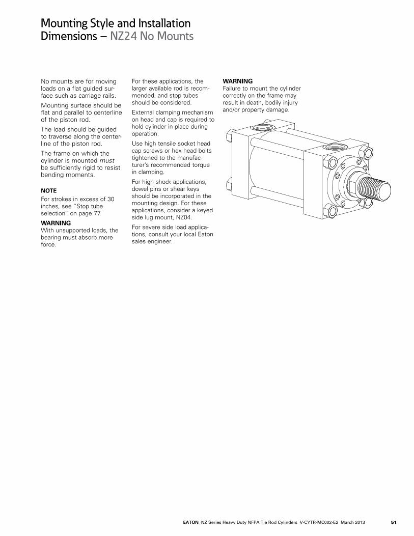
51EATON NZ Series Heavy Duty NFPA Tie Rod Cylinders V-CYTR-MC002-E2 March 2013
No mounts are for moving loads on a flat guided sur-face such as carriage rails.
Mounting surface should be flat and parallel to centerline of the piston rod.
The load should be guided to traverse along the center-line of the piston rod.
The frame on which the cylinder is mounted must be sufficiently rigid to resist bending moments.
NOTE For strokes in excess of 30 inches, see “Stop tube selection” on page 77.
WARNING With unsupported loads, the bearing must absorb more force.
For these applications, the larger available rod is recom-mended, and stop tubes should be considered.
External clamping mechanism on head and cap is required to hold cylinder in place during operation.
Use high tensile socket head cap screws or hex head bolts tightened to the manufac-turer’s recommended torque in clamping.
For high shock applications, dowel pins or shear keys should be incorporated in the mounting design. For these applications, consider a keyed side lug mount, NZ04..
For severe side load applica-tions, consult your local Eaton sales engineer.
WARNING Failure to mount the cylinder correctly on the frame may result in death, bodily injury and/or property damage.
Mounting Style and InstallationDimensions – NZ24 No Mounts

EATON NZ Series Heavy Duty NFPA Tie Rod Cylinders V-CYTR-MC002-E2 March 201352
+ Plus Stroke
ST
E
TS
US
RM
LH
1
2
3
4
SB BOLT
TWICE STROKE + ZM
XS
GG1
F
B
MM
V
C SY SU
STROKE+SS1 STROK+XS
G1
"K"
Mounting Style and InstallationDimensions – NZ25 Double Rod Side Lug Mount NFPA MS7 Mount
BoreRod Dia MM
B +.000/-.002 C E G F V RM
LH ±.002 SS1+
1.50 0.63 1.124. 0.38 2.50 1.75 0.38 0.25 - 1.24.3 4..13
1.00 1.4.99 0.50 2.50 1.75 0.38 0.50 - 1.24.3 4..13
2.00 1.00 1.4.99 0.50 3.00 1.75 0.63 0.25 - 1.4.93 3.88
1.38 1.999 0.63 3.00 1.75 0.63 0.38 - 1.4.93 3.88
2.50 1.00 1.4.99 0.50 3.50 1.75 0.50 0.38 2.63 1.74.3 3.63
1.38 1.999 0.63 3.50 1.75 0.63 0.38 - 1.74.3 3.63
1.75 2.374. 0.75 3.50 1.75 0.63 0.50 - 1.74.3 3.63
3.25 1.38 1.999 0.63 4..50 2.00 0.59 0.4.1 3.25 2.24.3 4..38
1.75 2.374. 0.75 4..50 2.00 0.75 0.38 - 2.24.3 4..38
2.00 2.624. 0.88 4..50 2.00 0.75 0.38 - 2.24.3 4..38
4..00 1.75 2.374. 0.75 5.00 2.00 0.59 0.53 3.88 2.4.93 4..25
2.00 2.624. 0.88 5.00 2.00 0.59 0.53 4..00 2.4.93 4..25
2.50 3.124. 1.00 5.00 2.00 0.59 0.66 4..4.4. 2.4.93 4..25
5.00 2.00 2.624. 0.88 6.50 2.00 0.59 0.53 4..00 3.24.3 4..75
2.50 3.124. 1.00 6.50 2.00 0.59 0.66 4..4.4. 3.24.3 4..75
3.00 3.74.9 1.00 6.50 2.00 0.72 0.53 5.25 3.24.3 4..75
3.50 4..24.9 1.00 6.50 2.00 0.72 0.53 5.63 3.24.3 4..75
6.00 2.50 3.124. 1.00 7.50 2.25 0.59 0.66 4..4.4. 3.74.3 5.13
3.00 3.74.9 1.00 7.50 2.25 0.72 0.53 5.25 3.74.3 5.13
3.50 4..24.9 1.00 7.50 2.25 0.72 0.53 5.63 3.74.3 5.13
4..00 4..74.9 1.00 7.50 2.25 0.88 0.38 6.4.4. 3.74.3 5.13
7.00 3.00 3.74.9 1.00 8.50 2.75 0.72 0.53 5.25 4..24.3 5.75
3.50 4..24.9 1.00 8.50 2.75 0.72 0.53 5.63 4..24.3 5.75
4..00 4..74.9 1.00 8.50 2.75 0.88 0.38 6.4.4. 4..24.3 5.75
4..50 5.24.9 1.00 8.50 2.75 0.88 0.38 7.13 4..24.3 5.75
5.00 5.74.9 1.00 8.50 2.75 0.88 0.38 7.56 4..24.3 5.75
8.00 3.50 4..24.9 1.00 9.50 3.00 0.72 0.53 5.63 4..74.3 6.75
4..00 4..74.9 1.00 9.50 3.00 0.88 0.38 6.4.4. 4..74.3 6.75
4..50 5.24.9 1.00 9.50 3.00 0.88 0.38 7.13 4..74.3 6.75
5.00 5.74.9 1.00 9.50 3.00 0.88 0.38 7.56 4..74.3 6.75
5.50 6.24.9 1.00 9.50 3.00 0.88 0.38 8.38 4..74.3 6.75

53EATON NZ Series Heavy Duty NFPA Tie Rod Cylinders V-CYTR-MC002-E2 March 2013
+ Plus Stroke
Double rod cylinders are specified when equal dis-placement is desired on both sides of the piston, or when the application is such that another function can be performed simultane-ously with a second rod. The single rod mount application data is also applicable to double rod cylinders. Rod and pilot related dimensions are typical for both ends.
WARNING Failure to mount the cylinder correctly on the frame may result in death, bodily injury and/or property damage.
Mounting Style and InstallationDimensions – NZ25 Double Rod Side Lug Mount NFPA MS7 Mount
BoreRod Dia MM ST SU SY TS US SB XS ZM+
Piston Thick. K
1.50 0.63 0.50 0.91 0.38 3.25 4..00 0.38 1.38 6.88 1.38 0.4.1
1.00 0.50 0.91 0.38 3.25 4..00 0.38 1.75 7.63 1.38 0.4.1
2.00 1.00 0.75 1.24. 0.50 4..00 5.00 0.50 1.88 7.63 1.38 0.55
1.38 0.75 1.24. 0.50 4..00 5.00 0.50 2.13 8.13 1.38 0.55
2.50 1.00 1.00 1.56 0.69 4..88 6.25 0.75 2.06 7.75 1.50 0.55
1.38 1.00 1.56 0.69 4..88 6.25 0.75 2.31 8.25 1.50 0.55
1.75 1.00 1.56 0.69 4..88 6.25 0.75 2.56 8.75 1.50 0.55
3.25 1.38 1.00 1.55 0.69 5.88 7.25 0.75 2.31 9.00 1.75 0.67
1.75 1.00 1.55 0.69 5.88 7.25 0.75 2.56 9.50 1.75 0.67
2.00 1.00 1.55 0.69 5.88 7.25 0.75 2.69 9.75 1.75 0.67
4..00 1.75 1.25 2.00 0.88 6.75 8.50 1.00 2.75 9.75 2.00 0.78
2.00 1.25 2.00 0.88 6.75 8.50 1.00 2.88 10.00 2.00 0.78
2.50 1.25 2.00 0.88 6.75 8.50 1.00 3.13 10.50 2.00 0.78
5.00 2.00 1.25 2.00 0.88 8.25 10.00 1.00 2.88 10.50 2.50 0.92
2.50 1.25 2.00 0.88 8.25 10.00 1.00 3.13 11.00 2.50 0.92
3.00 1.25 2.00 0.88 8.25 10.00 1.00 3.13 11.00 2.50 0.92
3.50 1.25 2.00 0.88 8.25 10.00 1.00 3.13 11.00 2.50 0.92
6.00 2.50 1.50 2.50 1.13 9.75 12.00 1.25 3.38 11.88 2.88 1.03
3.00 1.50 2.50 1.13 9.75 12.00 1.25 3.38 11.88 2.88 1.03
3.50 1.50 2.50 1.13 9.75 12.00 1.25 3.38 11.88 2.88 1.03
4..00 1.50 2.50 1.13 9.75 12.00 1.25 3.38 11.88 2.88 1.03
7.00 3.00 1.75 2.88 1.38 11.25 14..00 1.50 3.63 13.00 3.00 1.17
3.50 1.75 2.88 1.38 11.25 14..00 1.50 3.63 13.00 3.00 1.17
4..00 1.75 2.88 1.38 11.25 14..00 1.50 3.63 13.00 3.00 1.17
4..50 1.75 2.88 1.38 11.25 14..00 1.50 3.63 13.00 3.00 1.17
5.00 1.75 2.88 1.38 11.25 14..00 1.50 3.63 13.00 3.00 1.17
8.00 3.50 1.75 2.88 1.38 12.25 15.00 1.50 3.63 14..00 3.50 1.26
4..00 1.75 2.88 1.38 12.25 15.00 1.50 3.63 14..00 3.50 1.26
4..50 1.75 2.88 1.38 12.25 15.00 1.50 3.63 14..00 3.50 1.26
5.00 1.75 2.88 1.38 12.25 15.00 1.50 3.63 14..00 3.50 1.26
5.50 1.75 2.88 1.38 12.25 15.00 1.50 3.63 14..00 3.50 1.26
See Mount 24 on page 50 for Port Dimensions

EATON NZ Series Heavy Duty NFPA Tie Rod Cylinders V-CYTR-MC002-E2 March 201354
+ Plus Stroke
MR
E
E
CB +.000 -.030
RM1
2 4
3
CD
J
MM
B
CF
G
G1
VL
STROKE+XC
M
STROKE+LB
K
Mounting Style and InstallationDimensions – NZ47 Cap Fixed Eye Mount ANSI MP3
BoreRod Dia MM
B +.000/-.002 C E G J F V RM
1.50 0.63 1.124. 0.38 2.50 1.75 1.50 0.38 0.25 -
1.00 1.4.99 0.50 2.50 1.75 1.50 0.38 0.50 -
2.00 1.00 1.4.99 0.50 3.00 1.75 1.50 0.63 0.25 -
1.38 1.999 0.63 3.00 1.75 1.50 0.63 0.38 -
2.50 1.00 1.4.99 0.50 3.50 1.75 1.50 0.50 0.38 2.63
1.38 1.999 0.63 3.50 1.75 1.50 0.63 0.38 -
1.75 2.374. 0.75 3.50 1.75 1.50 0.63 0.50 -
3.25 1.38 1.999 0.63 4..50 2.00 1.75 0.59 0.4.1 3.25
1.75 2.374. 0.75 4..50 2.00 1.75 0.75 0.38 -
2.00 2.624. 0.88 4..50 2.00 1.75 0.75 0.38 -
4..00 1.75 2.374. 0.75 5.00 2.00 1.75 0.59 0.53 3.88
2.00 2.624. 0.88 5.00 2.00 1.75 0.59 0.53 4..00
2.50 3.124. 1.00 5.00 2.00 1.75 0.59 0.66 4..4.4.
5.00 2.00 2.624. 0.88 6.50 2.00 1.75 0.59 0.53 4..00
2.50 3.124. 1.00 6.50 2.00 1.75 0.59 0.66 4..4.4.
3.00 3.74.9 1.00 6.50 2.00 1.75 0.72 0.53 5.25
3.50 4..24.9 1.00 6.50 2.00 1.75 0.72 0.53 5.63
6.00 2.50 3.124. 1.00 7.50 2.25 2.25 0.59 0.66 4..4.4.
3.00 3.74.9 1.00 7.50 2.25 2.25 0.72 0.53 5.25
3.50 4..24.9 1.00 7.50 2.25 2.25 0.72 0.53 5.63
4..00 4..74.9 1.00 7.50 2.25 2.25 0.88 0.38 6.4.4.
7.00 3.00 3.74.9 1.00 8.50 2.75 2.75 0.72 0.53 5.25
3.50 4..24.9 1.00 8.50 2.75 2.75 0.72 0.53 5.63
4..00 4..74.9 1.00 8.50 2.75 2.75 0.88 0.38 6.4.4.
4..50 5.24.9 1.00 8.50 2.75 2.75 0.88 0.38 7.13
5.00 5.74.9 1.00 8.50 2.75 2.75 0.88 0.38 7.56
8.00 3.50 4..24.9 1.00 9.50 3.00 3.00 0.72 0.53 5.63
4..00 4..74.9 1.00 9.50 3.00 3.00 0.88 0.38 6.4.4.
4..50 5.24.9 1.00 9.50 3.00 3.00 0.88 0.38 7.13
5.00 5.74.9 1.00 9.50 3.00 3.00 0.88 0.38 7.56
5.50 6.24.9 1.00 9.50 3.00 3.00 0.88 0.38 8.38

55EATON NZ Series Heavy Duty NFPA Tie Rod Cylinders V-CYTR-MC002-E2 March 2013
+ Plus Stroke
These mounts are for applications in which the machine member travels in a curved path within one plane.
These mounts can be used both in compression (push) and tension (pull). Care must be exercised to prevent rod buckling in compres-sion applications with long strokes. See page 81 for stroke limitations.
NOTE For strokes in excess of 24. inches, see “Stop tube selection” on page 77.
WARNING The centerline of the machine member that attaches to the swivel pin must be perpendicular to the centerline of the piston rod and the curved path must be in one plane only. Any misalignment will cause excess side loading on the bearing and piston. This will lead to premature failure.
For applications with small amounts of misalignment,
consider the spherical bear-ing mount NZ11.
WARNING Failure to mount the cylinder correctly on the frame may result in death, bodily injury and/or property damage.
Mounting Style and InstallationDimensions – NZ47 Cap Fixed Eye Mount ANSI MP3
BoreRod Dia MM L M CB CD MR LB+ XC+
Piston Thick. K
1.50 0.63 0.75 0.50 0.75 0.500 0.56 4..63 6.38 1.38 0.4.1
1.00 0.75 0.50 0.75 0.500 0.56 4..63 6.75 1.38 0.4.1
2.00 1.00 1.25 0.75 1.25 0.750 1.06 4..63 7.25 1.38 0.55
1.38 1.25 0.75 1.25 0.750 1.06 4..63 7.50 1.38 0.55
2.50 1.00 1.25 0.75 1.25 0.750 1.06 4..75 7.38 1.50 0.55
1.38 1.25 0.75 1.25 0.750 1.06 4..75 7.63 1.50 0.55
1.75 1.25 0.75 1.25 0.750 1.06 4..75 7.88 1.50 0.55
3.25 1.38 1.50 1.00 1.50 1.000 1.13 5.50 8.63 1.75 0.67
1.75 1.50 1.00 1.50 1.000 1.13 5.50 8.88 1.75 0.67
2.00 1.50 1.00 1.50 1.000 1.13 5.50 9.00 1.75 0.67
4..00 1.75 2.13 1.38 2.00 1.375 1.75 5.75 9.75 2.00 0.78
2.00 2.13 1.38 2.00 1.375 1.75 5.75 9.88 2.00 0.78
2.50 2.13 1.38 2.00 1.375 1.75 5.75 10.13 2.00 0.78
5.00 2.00 2.25 1.75 2.50 1.750 1.88 6.25 10.50 2.50 0.92
2.50 2.25 1.75 2.50 1.750 1.88 6.25 10.75 2.50 0.92
3.00 2.25 1.75 2.50 1.750 1.88 6.25 10.75 2.50 0.92
3.50 2.25 1.75 2.50 1.750 1.88 6.25 10.75 2.50 0.92
6.00 2.50 2.50 2.00 2.50 2.000 2.13 7.38 12.13 2.88 1.03
3.00 2.50 2.00 2.50 2.000 2.13 7.38 12.13 2.88 1.03
3.50 2.50 2.00 2.50 2.000 2.13 7.38 12.13 2.88 1.03
4..00 2.50 2.00 2.50 2.000 2.13 7.38 12.13 2.88 1.03
7.00 3.00 3.00 2.50 3.00 2.500 2.50 8.50 13.75 3.00 1.17
3.50 3.00 2.50 3.00 2.500 2.50 8.50 13.75 3.00 1.17
4..00 3.00 2.50 3.00 2.500 2.50 8.50 13.75 3.00 1.17
4..50 3.00 2.50 3.00 2.500 2.50 8.50 13.75 3.00 1.17
5.00 3.00 2.50 3.00 2.500 2.50 8.50 13.75 3.00 1.17
8.00 3.50 3.25 2.75 3.00 3.000 2.75 9.50 15.00 3.50 1.26
4..00 3.25 2.75 3.00 3.000 2.75 9.50 15.00 3.50 1.26
4..50 3.25 2.75 3.00 3.000 2.75 9.50 15.00 3.50 1.26
5.00 3.25 2.75 3.00 3.000 2.75 9.50 15.00 3.50 1.26
5.50 3.25 2.75 3.00 3.000 2.75 9.50 15.00 3.50 1.26See Mount 24 on page 50 for Port Dimensions

EATON NZ Series Heavy Duty NFPA Tie Rod Cylinders V-CYTR-MC002-E2 March 201356
+ Plus Stroke
LR
MR
E
CB
E
RM
1
2
3
L
J
MM
B
C
FG
G1
V
FH STROKE+LB K
CD
M
STROKE+XC
4
Mounting Style and InstallationDimensions – NZ48 Cap Detachable Eye Mount ANSI MP4
BoreRod Dia MM
B +.000/-.002 C E G J F V RM L
1.50 0.63 1.124. 0.38 2.50 1.75 1.50 0.38 0.25 - 0.75
1.00 1.4.99 0.50 2.50 1.75 1.50 0.38 0.50 - 0.75
2.00 1.00 1.4.99 0.50 3.00 1.75 1.50 0.63 0.25 - 1.25
1.38 1.999 0.63 3.00 1.75 1.50 0.63 0.38 - 1.25
2.50 1.00 1.4.99 0.50 3.50 1.75 1.50 0.50 0.38 2.63 1.25
1.38 1.999 0.63 3.50 1.75 1.50 0.63 0.38 - 1.25
1.75 2.374. 0.75 3.50 1.75 1.50 0.63 0.50 - 1.25
3.25 1.38 1.999 0.63 4..50 2.00 1.75 0.59 0.4.1 3.25 1.50
1.75 2.374. 0.75 4..50 2.00 1.75 0.75 0.38 - 1.50
2.00 2.624. 0.88 4..50 2.00 1.75 0.75 0.38 - 1.50
4..00 1.75 2.374. 0.75 5.00 2.00 1.75 0.59 0.53 3.88 2.13
2.00 2.624. 0.88 5.00 2.00 1.75 0.59 0.53 4..00 2.13
2.50 3.124. 1.00 5.00 2.00 1.75 0.59 0.66 4..4.4. 2.13
5.00 2.00 2.624. 0.88 6.50 2.00 1.75 0.59 0.53 4..00 2.25
2.50 3.124. 1.00 6.50 2.00 1.75 0.59 0.66 4..4.4. 2.25
3.00 3.74.9 1.00 6.50 2.00 1.75 0.72 0.53 5.25 2.25
3.50 4..24.9 1.00 6.50 2.00 1.75 0.72 0.53 5.63 2.25
6.00 2.50 3.124. 1.00 7.50 2.25 2.25 0.59 0.66 4..4.4. 2.50
3.00 3.74.9 1.00 7.50 2.25 2.25 0.72 0.53 5.25 2.50
3.50 4..24.9 1.00 7.50 2.25 2.25 0.72 0.53 5.63 2.50
4..00 4..74.9 1.00 7.50 2.25 2.25 0.88 0.38 6.4.4. 2.50
7.00 3.00 3.74.9 1.00 8.50 2.75 2.75 0.72 0.53 5.25 3.00
3.50 4..24.9 1.00 8.50 2.75 2.75 0.72 0.53 5.63 3.00
4..00 4..74.9 1.00 8.50 2.75 2.75 0.88 0.38 6.4.4. 3.00
4..50 5.24.9 1.00 8.50 2.75 2.75 0.88 0.38 7.13 3.00
5.00 5.74.9 1.00 8.50 2.75 2.75 0.88 0.38 7.56 3.00
8.00 3.50 4..24.9 1.00 9.50 3.00 3.00 0.72 0.53 5.63 3.25
4..00 4..74.9 1.00 9.50 3.00 3.00 0.88 0.38 6.4.4. 3.25
4..50 5.24.9 1.00 9.50 3.00 3.00 0.88 0.38 7.13 3.25
5.00 5.74.9 1.00 9.50 3.00 3.00 0.88 0.38 7.56 3.25
5.50 6.24.9 1.00 9.50 3.00 3.00 0.88 0.38 8.38 3.25

57EATON NZ Series Heavy Duty NFPA Tie Rod Cylinders V-CYTR-MC002-E2 March 2013
+ Plus Stroke
These mounts are for applications in which the machine member travels in a curved path within one plane.
These mounts can be used both in compression (push) and tension (pull). Care must be exercised to prevent rod buckling in compres-sion applications with long strokes. See page 80 for stroke limitations.
NOTE For strokes in excess of 24. inches, see “Stop tube selection” on page 77.
WARNING The centerline of the machine member that attaches to the swivel pin must be perpendicular to the centerline of the piston rod and the curved path must be in one plane only. Any misalignment will cause excess side loading on the bearing and piston. This will lead to premature failure.
For applications with small amounts of misalignment, consider the spherical bearing mount NZ11.
WARNING Failure to mount the cylinder correctly on the frame may result in death, bodily injury and/or property damage.
Mounting Style and InstallationDimensions – NZ48 Cap Detachable Eye Mount ANSI MP4
BoreRod Dia MM M CB CD MR LB+ FH XC+
Piston Thick. K
1.50 0.63 0.50 0.75 0.500 0.56 4..63 0.38 6.75 1.38 0.4.1
1.00 0.50 0.75 0.500 0.56 4..63 0.38 7.13 1.38 0.4.1
2.00 1.00 0.75 1.25 0.750 1.06 4..63 0.63 7.88 1.38 0.55
1.38 0.75 1.25 0.750 1.06 4..63 0.63 8.13 1.38 0.55
2.50 1.00 0.75 1.25 0.750 1.06 4..75 0.63 8.00 1.50 0.55
1.38 0.75 1.25 0.750 1.06 4..75 0.63 8.25 1.50 0.55
1.75 0.75 1.25 0.750 1.06 4..75 0.63 8.50 1.50 0.55
3.25 1.38 1.00 1.50 1.000 1.13 5.50 0.75 9.38 1.75 0.67
1.75 1.00 1.50 1.000 1.13 5.50 0.75 9.63 1.75 0.67
2.00 1.00 1.50 1.000 1.13 5.50 0.75 9.75 1.75 0.67
4..00 1.75 1.38 2.00 1.375 1.75 5.75 0.88 10.63 2.00 0.78
2.00 1.38 2.00 1.375 1.75 5.75 0.88 10.75 2.00 0.78
2.50 1.38 2.00 1.375 1.75 5.75 0.88 11.00 2.00 0.78
5.00 2.00 1.75 2.50 1.750 1.88 6.25 0.88 11.38 2.50 0.92
2.50 1.75 2.50 1.750 1.88 6.25 0.88 11.63 2.50 0.92
3.00 1.75 2.50 1.750 1.88 6.25 0.88 11.63 2.50 0.92
3.50 1.75 2.50 1.750 1.88 6.25 0.88 11.63 2.50 0.92
6.00 2.50 2.00 2.50 2.000 2.13 7.38 1.00 13.13 2.88 1.03
3.00 2.00 2.50 2.000 2.13 7.38 1.00 13.13 2.88 1.03
3.50 2.00 2.50 2.000 2.13 7.38 1.00 13.13 2.88 1.03
4..00 2.00 2.50 2.000 2.13 7.38 1.00 13.13 2.88 1.03
7.00 3.00 2.50 3.00 2.500 2.50 8.50 1.00 14..75 3.00 1.17
3.50 2.50 3.00 2.500 2.50 8.50 1.00 14..75 3.00 1.17
4..00 2.50 3.00 2.500 2.50 8.50 1.00 14..75 3.00 1.17
4..50 2.50 3.00 2.500 2.50 8.50 1.00 14..75 3.00 1.17
5.00 2.50 3.00 2.500 2.50 8.50 1.00 14..75 3.00 1.17
8.00 3.50 2.75 3.00 3.000 2.75 9.50 1.00 16.00 3.50 1.26
4..00 2.75 3.00 3.000 2.75 9.50 1.00 16.00 3.50 1.26
4..50 2.75 3.00 3.000 2.75 9.50 1.00 16.00 3.50 1.26
5.00 2.75 3.00 3.000 2.75 9.50 1.00 16.00 3.50 1.26
5.50 2.75 3.00 3.000 2.75 9.50 1.00 16.00 3.50 1.26
See Mount 24 on page 50 for Port Dimensions

EATON NZ Series Heavy Duty NFPA Tie Rod Cylinders V-CYTR-MC002-E2 March 201358
+ Plus Stroke
M
LR
MR
RM
CBCW CW
E
E
1
2
3
25° J
MM
B
C
FG
G1
V
STROKE+XD
M L FH STROKE+LB K
CD
4
Mounting Style and InstallationDimensions – NZ50 Cap Detachable Clevis Mount ANSI MP2
BoreRod Dia MM
B +.000/-.002 C E G J F V RM FH L
1.50 0.63 1.124. 0.38 2.50 1.75 1.50 0.38 0.25 - 0.38 0.75
1.00 1.4.99 0.50 2.50 1.75 1.50 0.38 0.50 - 0.38 0.75
2.00 1.00 1.4.99 0.50 3.00 1.75 1.50 0.63 0.25 - 0.63 1.25
1.38 1.999 0.63 3.00 1.75 1.50 0.63 0.38 - 0.63 1.25
2.50 1.00 1.4.99 0.50 3.50 1.75 1.50 0.50 0.38 2.63 0.63 1.25
1.38 1.999 0.63 3.50 1.75 1.50 0.63 0.38 - 0.63 1.25
1.75 2.374. 0.75 3.50 1.75 1.50 0.63 0.50 - 0.63 1.25
3.25 1.38 1.999 0.63 4..50 2.00 1.75 0.59 0.4.1 3.25 0.75 1.50
1.75 2.374. 0.75 4..50 2.00 1.75 0.75 0.38 - 0.75 1.50
2.00 2.624. 0.88 4..50 2.00 1.75 0.75 0.38 - 0.75 1.50
4..00 1.75 2.374. 0.75 5.00 2.00 1.75 0.59 0.53 3.88 0.88 2.13
2.00 2.624. 0.88 5.00 2.00 1.75 0.59 0.53 4..00 0.88 2.13
2.50 3.124. 1.00 5.00 2.00 1.75 0.59 0.66 4..4.4. 0.88 2.13
5.00 2.00 2.624. 0.88 6.50 2.00 1.75 0.59 0.53 4..00 0.88 2.25
2.50 3.124. 1.00 6.50 2.00 1.75 0.59 0.66 4..4.4. 0.88 2.25
3.00 3.74.9 1.00 6.50 2.00 1.75 0.72 0.53 5.25 0.88 2.25
3.50 4..24.9 1.00 6.50 2.00 1.75 0.72 0.53 5.63 0.88 2.25
6.00 2.50 3.124. 1.00 7.50 2.25 2.25 0.59 0.66 4..4.4. 1.00 2.50
3.00 3.74.9 1.00 7.50 2.25 2.25 0.72 0.53 5.25 1.00 2.50
3.50 4..24.9 1.00 7.50 2.25 2.25 0.72 0.53 5.63 1.00 2.50
4..00 4..74.9 1.00 7.50 2.25 2.25 0.88 0.38 6.4.4. 1.00 2.50
7.00 3.00 3.74.9 1.00 8.50 2.75 2.75 0.72 0.53 5.25 1.00 3.00
3.50 4..24.9 1.00 8.50 2.75 2.75 0.72 0.53 5.63 1.00 3.00
4..00 4..74.9 1.00 8.50 2.75 2.75 0.88 0.38 6.4.4. 1.00 3.00
4..50 5.24.9 1.00 8.50 2.75 2.75 0.88 0.38 7.13 1.00 3.00
5.00 5.74.9 1.00 8.50 2.75 2.75 0.88 0.38 7.56 1.00 3.00
8.00 3.50 4..24.9 1.00 9.50 3.00 3.00 0.72 0.53 5.63 1.00 3.25
4..00 4..74.9 1.00 9.50 3.00 3.00 0.88 0.38 6.4.4. 1.00 3.25
4..50 5.24.9 1.00 9.50 3.00 3.00 0.88 0.38 7.13 1.00 3.25
5.00 5.74.9 1.00 9.50 3.00 3.00 0.88 0.38 7.56 1.00 3.25
5.50 6.24.9 1.00 9.50 3.00 3.00 0.88 0.38 8.38 1.00 3.25

59EATON NZ Series Heavy Duty NFPA Tie Rod Cylinders V-CYTR-MC002-E2 March 2013
+ Plus Stroke
These mounts are for applications in which the machine member travels in a curved path within one plane.
These mounts can be used both in compression (push) and tension (pull). Care must be exercised to prevent rod buckling in compres-sion applications with long strokes. See page 80 for stroke limitations.
NOTE For strokes in excess of 24. inches, see “Stop tube selection” on page 77.
WARNING The centerline of the machine member that attaches to the swivel pin must be perpendicular to the centerline of the piston rod and the curved path must be in one plane only. Any misalignment will cause excess side loading on the bearing and piston. This will lead to premature failure.
For applications with small amounts of misalignment, consider the spherical bearing mount NZ11.
WARNING Failure to mount the cylinder correctly on the frame may result in death, bodily injury and/or property damage.
Mounting Style and InstallationDimensions – NZ50 Cap Detachable Clevis Mount ANSI MP2
BoreRod Dia MM M CB
CD+.000/-.002 CW LR MR LB+ XD+
Piston Thick. K
1.50 0.63 0.50 0.75 0.500 0.50 0.56 0.56 4..63 6.75 1.38 0.4.1
1.00 0.50 0.75 0.500 0.50 0.56 0.56 4..63 7.13 1.38 0.4.1
2.00 1.00 0.75 1.25 0.750 0.63 1.06 1.06 4..63 7.88 1.38 0.55
1.38 0.75 1.25 0.750 0.63 1.06 1.06 4..63 8.13 1.38 0.55
2.50 1.00 0.75 1.25 0.750 0.63 1.06 1.06 4..75 8.00 1.50 0.55
1.38 0.75 1.25 0.750 0.63 1.06 1.06 4..75 8.25 1.50 0.55
1.75 0.75 1.25 0.750 0.63 1.06 1.06 4..75 8.50 1.50 0.55
3.25 1.38 1.00 1.50 1.000 0.75 1.25 1.13 5.50 9.38 1.75 0.67
1.75 1.00 1.50 1.000 0.75 1.25 1.13 5.50 9.63 1.75 0.67
2.00 1.00 1.50 1.000 0.75 1.25 1.13 5.50 9.75 1.75 0.67
4..00 1.75 1.38 2.00 1.375 1.00 1.88 1.75 5.75 10.63 2.00 0.78
2.00 1.38 2.00 1.375 1.00 1.88 1.75 5.75 10.75 2.00 0.78
2.50 1.38 2.00 1.375 1.00 1.88 1.75 5.75 11.00 2.00 0.78
5.00 2.00 1.75 2.50 1.750 1.25 1.94. 1.88 6.25 11.38 2.50 0.92
2.50 1.75 2.50 1.750 1.25 1.94. 1.88 6.25 11.63 2.50 0.92
3.00 1.75 2.50 1.750 1.25 1.94. 1.88 6.25 11.63 2.50 0.92
3.50 1.75 2.50 1.750 1.25 1.94. 1.88 6.25 11.63 2.50 0.92
6.00 2.50 2.00 2.50 2.000 1.25 2.06 2.13 7.38 13.13 2.88 1.03
3.00 2.00 2.50 2.000 1.25 2.06 2.13 7.38 13.13 2.88 1.03
3.50 2.00 2.50 2.000 1.25 2.06 2.13 7.38 13.13 2.88 1.03
4..00 2.00 2.50 2.000 1.25 2.06 2.13 7.38 13.13 2.88 1.03
7.00 3.00 2.50 3.00 2.500 1.50 2.56 2.50 8.50 14..75 3.00 1.17
3.50 2.50 3.00 2.500 1.50 2.56 2.50 8.50 14..75 3.00 1.17
4..00 2.50 3.00 2.500 1.50 2.56 2.50 8.50 14..75 3.00 1.17
4..50 2.50 3.00 2.500 1.50 2.56 2.50 8.50 14..75 3.00 1.17
5.00 2.50 3.00 2.500 1.50 2.56 2.50 8.50 14..75 3.00 1.17
8.00 3.50 2.75 3.00 3.000 1.50 2.69 2.75 9.50 16.00 3.50 1.26
4..00 2.75 3.00 3.000 1.50 2.69 2.75 9.50 16.00 3.50 1.26
4..50 2.75 3.00 3.000 1.50 2.69 2.75 9.50 16.00 3.50 1.26
5.00 2.75 3.00 3.000 1.50 2.69 2.75 9.50 16.00 3.50 1.26
5.50 2.75 3.00 3.000 1.50 2.69 2.75 9.50 16.00 3.50 1.26
See Mount 24 on page 50 for Port Dimensions

EATON NZ Series Heavy Duty NFPA Tie Rod Cylinders V-CYTR-MC002-E2 March 201360
Technical Data
Accessories
WARNINGAll rod accessories must be torqued against the rod shoul-der. Mounting brackets, rod clev-ises, and rod eyes for all NZ cylinders are available from Eaton. These accessories are detailed below showing part numbers and all pertinent dimensional data. Make sure the rod end type selected has threads that match the threads of any required acces-sory. Dimensions are in inch-es unless otherwise noted. When ordering, please specify the part name and part num-ber. It is user’s responsibility to select the correct acces-sory. WARNING Failure to mount the cylinder correctly on the frame may result in death, bodily injury and/or property damage.
WARNING It is the user’s responsibility to select the correct acces-sory.
WARNINGS – Piston Rods
Cylinder users must always make sure that the piston rod is securely attached to the machine member.
Piston rods are not normally designed to absorb bend-ing moments or loads which are perpendicular to the axis of piston rod motion. These additional loads can cause the piston rod end to fail. If these types of additional loads are expected to be imposed on the piston rods, their magnitude should be made known to our Engineering Department so they may be properly addressed.
On occasion, cylinders are ordered with double rods. In some cases, a stop is thread-ed onto one of the piston rods and used as an external stroke adjuster. This type of
usage may result in a poten-tial safety hazard and can also lead to premature piston rod failure. The external stop will create a pinch point. As a result, the cylinder user must use guards.
Furthermore, if an external stop is not parallel to the final contact surface, it will place a bending moment on the piston rod. An external stop will also negate the effect of a cushion and will subject the piston rod to an impact load-ing. These two (2) conditions can cause premature piston rod failure. The use of external stroke adjusters should be reviewed with our Engineering Department.
WARNINGS – Mounting & Accessories
The cylinder user should avoid severe vibration and high impact load. Severe vibration can cause joints to become loose. A high impact load can reduce the fatigue life of the
piston rod, rod end, acces-sories and other components. Consult the Eaton Engineering Department if there is severe vibration or a high impact load.
Proper selection and instal-lation of the mounting style options and accessories will improve cylinder perfor-mance and extend service life. Cylinders are capable of generating a very high force, so proper selection and main-tenance is necessary. It is the user’s responsibility to ensure proper selection and installa-tion.
The failure to select the cor-rect mounting options and accessories, the failure to mount the cylinder correctly and/or the failure to install the piston rod, rod ends, acces-sories and other components correctly may cause or result in Death, Bodily Injury and/or Property Damage.
Rod Eye
CD
CDCD
ER
A
CAFullthd
KK
CD
CB
Bore KK Torque* (ft-lb)
PartNumber
Weight (lbs) A CA CB CD ER
1.50 7/16–20 UNF–2B 36 FRE-04.37 0.38 0.75 1.50 0.75 0.50 0.63
2.00 3/4.–16 UNF–2B 125 FRE-0750 1.25 1.13 2.06 1.25 0.75 0.88
2.50 3/4.–16 UNF–2B 125 FRE-0750 1.25 1.13 2.06 1.25 0.75 0.88
3.25 1–14. NS–2B 250 FRE-1000 2.5 1.63 2.81 1.50 1.00 1.18
4..00 1 1/4.–12 UNF–2B 4.60 FRE-1250 5.94. 2.00 3.4.4. 2.00 1.38 1.56
5.00 1 1/2–12 UNF–2B 663 FRE-1500 11.4. 2.25 4..00 2.50 1.75 2.00
6.00 1 7/8–12 UNF–2B 94.4. FRE-1875 15.1 3.00 5.00 2.50 2.00 2.25
7.00 2 1/4.–12 UNF–2B 1315 FRE-2250 27 3.50 5.81 3.00 2.50 2.81
8.00 2 1/2–12 UNF–2B 5050 FRE-2500 35 3.50 6.12 3.00 3.00 3.25
* Recommended torque values using MoS2 lubricant with 0.12 co-efficient of friction.
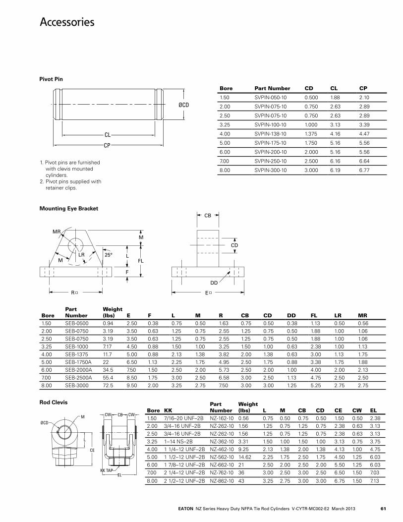
61EATON NZ Series Heavy Duty NFPA Tie Rod Cylinders V-CYTR-MC002-E2 March 2013
CP
ØCD
CL
Accessories
Mounting Eye Bracket
CD
CB
25°
E
DD
LR LFL
MMR
M
F
R
Bore Part Number
Weight (lbs) E F L M R CB CD DD FL LR MR
1.50 SEB-0500 0.94. 2.50 0.38 0.75 0.50 1.63 0.75 0.50 0.38 1.13 0.50 0.562.00 SEB-0750 3.19 3.50 0.63 1.25 0.75 2.55 1.25 0.75 0.50 1.88 1.00 1.062.50 SEB-0750 3.19 3.50 0.63 1.25 0.75 2.55 1.25 0.75 0.50 1.88 1.00 1.063.25 SEB-1000 7.17 4..50 0.88 1.50 1.00 3.25 1.50 1.00 0.63 2.38 1.00 1.134..00 SEB-1375 11.7 5.00 0.88 2.13 1.38 3.82 2.00 1.38 0.63 3.00 1.13 1.755.00 SEB-1750A 22 6.50 1.13 2.25 1.75 4..95 2.50 1.75 0.88 3.38 1.75 1.886.00 SEB-2000A 34..5 7.50 1.50 2.50 2.00 5.73 2.50 2.00 1.00 4..00 2.00 2.137.00 SEB-2500A 55.4. 8.50 1.75 3.00 2.50 6.58 3.00 2.50 1.13 4..75 2.50 2.508.00 SEB-3000 72.5 9.50 2.00 3.25 2.75 7.50 3.00 3.00 1.25 5.25 2.75 2.75
Bore KKPart Number
Weight (lbs) L M CB CD CE CW EL
1.50 7/16–20 UNF–2B NZ-162-10 0.56 0.75 0.50 0.75 0.50 1.50 0.50 2.382.00 3/4.–16 UNF–2B NZ-262-10 1.56 1.25 0.75 1.25 0.75 2.38 0.63 3.132.50 3/4.–16 UNF–2B NZ-262-10 1.56 1.25 0.75 1.25 0.75 2.38 0.63 3.133.25 1–14. NS–2B NZ-362-10 3.31 1.50 1.00 1.50 1.00 3.13 0.75 3.754..00 1 1/4.–12 UNF–2B NZ-4.62-10 9.25 2.13 1.38 2.00 1.38 4..13 1.00 4..755.00 1 1/2–12 UNF–2B NZ-562-10 14..62 2.25 1.75 2.50 1.75 4..50 1.25 6.036.00 1 7/8–12 UNF–2B NZ-662-10 21 2.50 2.00 2.50 2.00 5.50 1.25 6.037.00 2 1/4.–12 UNF–2B NZ-762-10 36 3.00 2.50 3.00 2.50 6.50 1.50 7.03
8.00 2 1/2–12 UNF–2B NZ-862-10 4.3 3.25 2.75 3.00 3.00 6.75 1.50 7.13
Rod Clevis
EL
CW CB CW
KK TAP
L
ØCD
CE
M
Pivot Pin
Bore Part Number CD CL CP
1.50 SVPIN-050-10 0.500 1.88 2.10
2.00 SVPIN-075-10 0.750 2.63 2.89
2.50 SVPIN-075-10 0.750 2.63 2.89
3.25 SVPIN-100-10 1.000 3.13 3.39
4..00 SVPIN-138-10 1.375 4..16 4..4.7
5.00 SVPIN-175-10 1.750 5.16 5.56
6.00 SVPIN-200-10 2.000 5.16 5.56
7.00 SVPIN-250-10 2.500 6.16 6.64.
8.00 SVPIN-300-10 3.000 6.19 6.771. Pivot pins are furnished with clevis mounted cylinders.2. Pivot pins supplied with
retainer clips.

EATON NZ Series Heavy Duty NFPA Tie Rod Cylinders V-CYTR-MC002-E2 March 201362
Clevis Bracket
CB*E FJ
DD TAP(4) PLACES
BABA2
MSQ
AAB.C.
M
APPROX.
25°
LR
FH
+ .004+ .002
CD
MR
CW CW
Bore Part No. AA BA CB CD CW DD E FH FJ LR M MR1.50 ECB-0500 2.30 1.63 0.78 0.500 0.50 3/8-24. 2.50 0.38 1.38 0.50 0.50 0.562.00 ECB-0750 2.90 2.06 0.59 0.750 0.63 1/2-20 3.00 0.63 1.88 1.00 0.75 0.692.50 ECB-0750A 3.60 2.56 0.59 0.750 0.63 1/2-20 3.50 0.63 1.88 1.06 0.75 0.693.25 ECB-1000 4..60 3.25 1.53 1.000 0.75 5/8-18 4..50 0.75 2.25 1.25 1.00 1.134..00 ECB-1380 5.4.0 3.81 2.03 1.375 1.00 5/8-18 5.00 0.88 3.00 1.88 1.38 1.755.00 ECB-1750 7.00 4..94. 2.53 1.750 1.25 7/8-14. 6.50 0.88 3.13 2.00 1.75 1.886.00 ECB-2000 8.10 5.75 2.53 2.000 1.25 1-14. 7.50 1.00 3.50 2.13 2.00 2.137.00 ECB-2500 9.30 6.59 3.03 2.500 1.50 1 1/8-12 8.50 1.00 4..00 2.63 2.50 2.508.00 ECB-3000 10.60 7.50 3.03 3.000 1.50 1 1/4.-12 9.50 1.00 4..25 2.88 2.75 2.75
Spherical Rod Eye
CD+.0000–.0005
LE
ER (MAX)
CE
A
KKTHD
LUBEFITTING
JLDIA.
EX
Bore KK Part No. A
CD +.0000 -.0005 CE EX ER JL LE
Load Capacity (lbs)
1.50 7/16-20 BRE-04.37 0.69 0.5000 0.88 0.4.4. 0.88 0.88 0.75 2600
2.00 3/4.-16 BRE-0750 1.00 0.7500 1.25 0.66 1.25 1.31 1.06 94.00
2.50 3/4.-16 BRE-0750 1.00 0.7500 1.25 0.66 1.25 1.31 1.06 94.00
3.25 1-14. BRE-1000 1.50 1.0000 1.88 0.88 1.38 1.50 1.4.4. 16800
4..00 1 1/4.-12 BRE-1250 2.00 1.3750 2.13 1.19 1.81 2.00 1.88 28600
5.00 1 1/2-12 BRE-1500 2.13 1.7500 2.50 1.53 2.19 2.25 2.13 4.3000
6.00 1 7/8-12 BRE-1875 2.88 2.0000 2.75 1.75 2.63 2.75 2.50 70000
Accessories

63EATON NZ Series Heavy Duty NFPA Tie Rod Cylinders V-CYTR-MC002-E2 March 2013
ØCD
CL
Accessories – For Spherical Bushing Mounted Cylinder
Spherical Clevis Bracket
Bore Part No. BA CB CD CW DD E FH FL LR M MR1.50 SCB-0500 2.05 0.4.4. 0.500 0.50 0.4.1 3.00 0.50 1.50 0.94. 0.50 0.622.00 SCB-0750 2.76 0.66 0.750 0.62 0.53 3.75 0.62 2.00 1.38 0.88 1.002.50 SCB-0750 2.76 0.66 0.750 0.62 0.53 3.75 0.62 2.00 1.38 0.88 1.003.25 SCB-1000 4..10 0.88 1.000 0.75 0.53 5.50 0.75 2.50 1.69 1.00 1.194..00 SCB-1380 4..95 1.19 1.375 1.00 0.66 6.50 0.88 3.50 2.4.4. 1.38 1.625.00 SCB-1750 6.58 1.53 1.750 1.25 0.91 8.50 1.25 4..50 2.88 1.75 2.066.00 SCB-2000 7.92 1.75 2.000 1.50 0.91 10.62 1.50 5.00 3.31 2.00 2.38
Pivot Pin - for Spherical Bearing
Bore Part No. CD CL
1.50 SBPIN-050-10 0.500 1.56
2.00 SBPIN-075-10 0.750 2.03
2.50 SBPIN-075-10 0.750 2.03
3.25 SBPIN-100-10 1.000 2.50
4..00 SBPIN-138-10 1.375 3.31
5.00 SBPIN-175-10 1.750 4..22
6.00 SBPIN-200-10 2.000 4..94.
1. Pivot pins supplied with retainer clips.

EATON NZ Series Heavy Duty NFPA Tie Rod Cylinders V-CYTR-MC002-E2 March 201364
Rod End Couplings
Used with the Vickers style G Rod End, the Vickers Rod End Coupling provides for close lateral alignment between the rod end and machine member. The two-piece steel coupling features high tensile strength socket head cap screws (with safety factor designed to take full load), permits quick assembly/disassembly for fast and easy installation and servicing.
Weld Plate L N PSco. Hd. Cap Screws
Bolt Torq. Ft. lb. S T U X
WP-05 0.50 2.00 0.25 #10-24.x.88 5 0.4.0 – – –
WP-08 0.50 2.50 0.25 1/4.”-20x1.0 14. 0.38 0.75 0.65 –
WP-11 0.62 3.00 0.25 5/16”-18x1.25 30 0.50 1.00 0.87 –
WP-14. 0.75 3.50 0.25 3/8”-16x1.5 52 0.4.5 1.10 – –
WP-16 0.88 4..00 0.38 3/8”-16x2.0 52 0.35 0.95 1.30 –
WP-20 1.00 5.00 0.38 1/2”-13x2.25 128 0.66 1.59 – –
WP-24. 1.00 5.50 0.38 1/2”-13x2.75 128 0.52 1.4.1 1.93 –
WP-28 1.12 6.50 0.38 5/8”-11x3.0 255 0.61 1.66 2.26 –
WP-32 1.12 7.00 0.38 5/8”-11x3.0 255 0.67 1.83 2.51 –
WP-36 1.25 7.50 0.38 3/4.”-10x3.5 4.50 1.09 2.63 – –
WP-4.0 1.38 8.00 0.38 5/8”-11x3.75 255 0.80 2.19 2.99 –
WP-4.4. 1.50 9.00 0.38 3/4.”-10x4..5 4.50 0.89 2.4.3 3.32 –
A
SMMDN
CAF
A
B
L
MOUNT -05
S HE DIA.F # BOLTS
G DIA.B.C.
U
MOUNT -08, -11
S
THE DIA.
F NO. BOLTS
G DIA B.C.
T
S
MOUNT -14, -20, -36
S
THE DIA.
F NO. BOLTS
G DIA.B.C.
SS
H
G DIA.B.C.
MOUNT-16, -24, -28,-32, -40, -44,
TU TU
E DIA.F NO.BOLTS
MOUNT -64, -80
Typical section AAdepending on rod diameter
H
C-272-Weld PlateP DIA.
Locator Pin
C-271-Coupling
K
Quick connect- disconnect coupling
Weld-plate
Locatorpin
Machinemember
A
SMMDN
CAF
A
B
L
MOUNT -05
S HE DIA.F # BOLTS
G DIA.B.C.
U
MOUNT -08, -11
S
THE DIA.
F NO. BOLTS
G DIA B.C.
T
S
MOUNT -14, -20, -36
S
THE DIA.
F NO. BOLTS
G DIA.B.C.
SS
H
G DIA.B.C.
MOUNT-16, -24, -28,-32, -40, -44,
TU TU
E DIA.F NO.BOLTS
MOUNT -64, -80
Typical section AAdepending on rod diameter
H
C-272-Weld PlateP DIA.
Locator Pin
C-271-Coupling
K
Quick connect- disconnect coupling
Weld-plate
Locatorpin
Machinemember
�� Eaton Vickers Small Bore Cylinder Catalog V-CYTR-MC002-E November 2007
Rod End Couplings
Used with the Hydro-Linestyle 10 Rod End, the Hydro-Line Rod End Coupling pro-vides for close lateral align-ment between the rod endand machine member. The two-piece steel coupling features high tensile strength socket head cap screws (with safety factor designed to take full load), permits quick assembly/disassembly for fast and easy installation and servicing.
Coupling and Weld plate Assembly
Coupling NZ-��1-
Rod Dia (MM) AF B C D E F G H K
NZ-275-05 NZ-271-05 0.63 0.38 0.44 0.41 1.50 0.22 4.00 1.12 45° 0.44
NZ-275-08 NZ-271-08 1.00 0.69 0.62 0.75 2.00 0.28 6.00 1.50 30° 0.38
NZ-275-11 NZ-271-11 1.38 0.88 0.69 0.94 2.50 0.34 6.00 2.00 30° 0.56
NZ-275-14 NZ-271-14 1.75 1.12 0.88 1.18 3.00 0.41 8.00 2.38 22° 30’ 0.62
NZ-275-16 NZ-271-16 2.00 1.38 1.25 1.44 3.50 0.41 12.00 2.69 15° 0.75
NZ-275-20 NZ-271-20 2.50 1.75 1.38 1.88 4.25 0.53 8.00 3.44 22° 30’ 0.88
NZ-275-24 NZ-271-24 3.00 2.25 1.88 2.38 5.00 0.53 12.00 4.00 15° 0.88
NZ-275-28 NZ-271-28 3.50 2.50 2.00 2.62 5.88 0.66 12.00 4.69 15° 1.00
NZ-275-32 NZ-271-32 4.00 3.00 2.00 3.12 6.38 0.66 12.00 5.18 15° 1.00
NZ-275-36 NZ-271-36 4.50 3.50 2.38 3.62 6.88 0.78 8.00 5.69 22° 30’ 1.12
NZ-275-40 NZ-271-40 5.00 3.88 2.50 4.00 7.38 0.66 12.00 6.18 15° 1.25
NZ-275-44 NZ-271-44 5.50 4.38 3.12 4.50 8.25 0.78 12.00 6.88 15° 1.38
Weld Plate NZ-���- L N PSco. Hd. Cap Screws
Bolt Torq. Ft. lb. S T U X
NZ-272-05 0.50 2.00 0.25 #10-24x.88 5 0.40 – – –
NZ-272-08 0.50 2.50 0.25 1/4”-20x1.0 14 0.38 0.75 0.65 –
NZ-272-11 0.62 3.00 0.25 5/16”-18x1.25 30 0.50 1.00 0.87 –
NZ-272-14 0.75 3.50 0.25 3/8”-16x1.5 52 0.45 1.10 – –
NZ-272-16 0.88 4.00 0.38 3/8”-16x2.0 52 0.35 0.95 1.30 –
NZ-272-20 1.00 5.00 0.38 1/2”-13x2.25 128 0.66 1.59 – –
NZ-272-24 1.00 5.50 0.38 1/2”-13x2.75 128 0.52 1.41 1.93 –
NZ-272-28 1.12 6.50 0.38 5/8”-11x3.0 255 0.61 1.66 2.26 –
NZ-272-32 1.12 7.00 0.38 5/8”-11x3.0 255 0.67 1.83 2.51 –
NZ-272-36 1.25 7.50 0.38 3/4”-10x3.5 450 1.09 2.63 – –
NZ-272-40 1.38 8.00 0.38 5/8”-11x3.75 255 0.80 2.19 2.99 –
NZ-272-44 1.50 9.00 0.38 3/4”-10x4.5 450 0.89 2.43 3.32 –
A
SMMDN
CAF
A
B
L
MOUNT -05
S HE DIA.F # BOLTS
G DIA.B.C.
U
MOUNT -08, -11
S
THE DIA.
F NO. BOLTS
G DIA B.C.
T
S
MOUNT -14, -20, -36
S
THE DIA.
F NO. BOLTS
G DIA.B.C.
SS
H
G DIA.B.C.
MOUNT-16, -24, -28,-32, -40, -44,
TU TU
E DIA.F NO.BOLTS
MOUNT -64, -80
Typical section AAdepending on rod diameter
H
C-272-Weld PlateP DIA.
Locator Pin
C-271-Coupling
K
Quick connect- disconnect coupling
Weld-plate
Locatorpin
Machinemember
A
SMMDN
CAF
A
B
L
MOUNT -05
S HE DIA.F # BOLTS
G DIA.B.C.
U
MOUNT -08, -11
S
THE DIA.
F NO. BOLTS
G DIA B.C.
T
S
MOUNT -14, -20, -36
S
THE DIA.
F NO. BOLTS
G DIA.B.C.
SS
H
G DIA.B.C.
MOUNT-16, -24, -28,-32, -40, -44,
TU TU
E DIA.F NO.BOLTS
MOUNT -64, -80
Typical section AAdepending on rod diameter
H
C-272-Weld PlateP DIA.
Locator Pin
C-271-Coupling
K
Quick connect- disconnect coupling
Weld-plate
Locatorpin
Machinemember

65EATON NZ Series Heavy Duty NFPA Tie Rod Cylinders V-CYTR-MC002-E2 March 2013
Self-Aligning Coupler
Lateral movement (on push only) and radial movement provide precision align-ment between cylinder and machine. Couplers preset with proper clearances and completely lubricated at factory before shipping.
Note
When ordering oversize and 2:1 rod cylinders, specify modification to suit standard rod diameter’s coupler.
Part No.“A” Thread B C D E F G H J K
M° of Move-ment
Load Rat-ing Max Pull at Yield (lbs)
SAC-0312 5/16-24 0.88 1.25 0.25 0.63 0.31 0.25 0.81 – – 1 4,000
SAC-0375 3/8-24 0.88 1.25 0.25 0.63 0.37 0.31 0.81 – – 1 5,000
SAC-0437 7/16-20 1.25 2.00 0.50 0.75 0.63 0.56 1.13 – – 1 10,000
SAC-0500 1/2-20 1.25 2.00 0.50 0.75 0.63 0.56 1.13 – – 1 14,000
SAC-0625 5/8-18 1.25 2.00 0.50 0.75 0.63 0.50 1.13 – – 1 14,000
SAC-0750 3/4-16 1.75 2.31 0.31 1.13 0.97 0.88 1.50 – – 1 34,000
SAC-0875 7/8-14 1.75 2.31 0.31 1.13 0.97 0.88 1.50 – – 1 34,000
SAC-1000 1-14 2.50 2.94 0.50 1.63 1.38 1.25 2.25 – – 1 64,000
SAC-1250 1-1/4-12 2.50 2.94 0.50 1.63 1.38 1.25 2.25 – – 1 64,000
SAC-1500 1-1/2-12 3.25 4.38 0.81 2.25 1.75 1.50 3.00 – – 1 120,000
SAC-1750 1-3/4-12 3.25 4.38 0.81 2.25 1.75 1.50 3.00 – – 1 120,000
SAC-1875 1-7/8-12 3.75 5.44 0.69 3.00 2.25 1.88 3.50 – – 1 240,000
SAC-2000 2-12 3.75 5.44 0.69 3.00 2.25 1.88 3.50 – – 1 240,000
SAC-2250 2-1/4-12 6.75 6.38 – 3.50 2.75 2.38 2.88 1.63 3.38 10 397,000
SAC-2500 2-1/2-12 7.00 6.50 – 3.50 3.25 2.88 3.38 1.63 3.88 10 495,000
SAC-2375 2-3/4-12 7.00 6.50 – 3.50 3.25 2.88 3.38 1.63 3.88 10 603,800
SAC-3000 3-12 7.00 6.50 – 3.50 3.25 2.88 3.38 1.63 3.88 10 723,040
SAC-3250 3-1/4-12 9.25 8.50 – 4.50 4.00 3.38 4.50 2.00 5.50 10 853,800
SAC-4000 4 -12 7.25 9.38 1.00 5.50 5.47 * 1.88 - - 1 750,010
SAC-4250 4-1/4-12 12.88 11.25 – 4.50 5.50 4.88 7.00 1.50 8.75 10 1,483,400
ØB
1°SphericalMovement
Float
1/16Radial
C
E
E
ØF
DGA/CFlats
HA/CFlats
AThread A Thread
E Deep
ØB 10°Total
Movement
CE
K JØF
HA/cFlats
GA/cFlats
A Thread
A ThreadE Deep
SAC-0312 Thru SAC-2000, SAC-4.000
SAC-2250 Thru SAC-3250, SAC-4.250

EATON NZ Series Heavy Duty NFPA Tie Rod Cylinders V-CYTR-MC002-E2 March 201366
Rod End Types
In addition to selecting the correct bore, you must spec-ify the appropriate rod size and rod ends configuration for your application.
Twelve different inch and Metric rod ends configura-tions are available. If a cus-tom design is required con-
tact your local Eaton sales engineer and we will build to your requirements.
Table on page 80 gives maximum allowable push length at various operating pressures for available rod diameters. Rod ends on rigid mount should be supported.
Longer strokes allowable for pull only applications.
Contact your local Eaton sales engineer for applica-tion assistance if necessary
Note: Code 0 , 1, and N threads are to ISO 4.395 and are based on the metric fine pitch series. Rod end acces-
sories locknuts, tooling and guages are available. These threads are also specified in ISO 6020-2 (160 Bar com-pact) cylinder series. Code 7 and L threads are based on the closest metric threads to the UN series and are recommended for replace-ment only.
Code
5 K
Inch Rod Ends
D across flatsD across flatsAC
KKNA
MM
D across flats
9 M
D across flats
2
D across flatsA
C
NAMM
KK
C
MM
6
AC
G
MM
ADAE
∅AF
1/16 R1/8 R
1/32 R1/8 R
Forrod
sizes31/2”thru51/2”
Code
Code
Code
Code
Code
Code
AC
NAMM CC
AXC
NAMM KK
AXC
NAMM CC
AC
NAMM DC ∅ 4 holes
KK or CC
Rod ∅ MM
UN(F) Thread
A C D AC AD AE AF AX DC CC KK NA
0.625 0.75 0.38 0.50 1.13 0.63 0.38 0.25 1.13 - 1/2-10 7/16-20 0.585
1.000 1.13 0.50 0.88 1.50 0.94. 0.69 0.38 1.69 - 7/8-14. 3/4.-16 0.968
1.375 1.63 0.63 1.13 1.75 1.06 0.88 0.38 2.4.4. - 1 1/4.-12 1-14. 1.34.3
1.750 2.00 0.75 1.50 2.00 1.31 1.13 0.50 3.00 - 1 1/2-12 1 1/4.-12 1.718
2.000 2.25 0.88 1.75 2.63 1.69 1.38 0.63 3.38 - 1 3/4.-12 1 1/2-12 1.953
2.500 3.00 1.00 2.13 3.25 1.94. 1.75 0.75 4..50 - 2 1/4.-12 1 7/8-12 2.4.37
3.000 3.50 1.00 2.63 3.63 2.4.4. 2.25 0.88 5.25 - 2 3/4.-12 2 1/4.-12 2.937
3.500 3.50 1.00 3.00 4..38 2.69 2.50 1.00 5.25 - 3 1/4.-12 2 1/2-12 3.4.37
4..000 4..00 1.00 - 4..50 2.69 3.00 1.00 6.00 0.50 3 3/4.-12 3-12 3.906
4..500 4..50 1.00 - 5.25 3.19 3.50 1.50 6.75 0.50 4. 1/4.-12 3 1/4.-12 4..4.06
5.000 5.00 1.00 - 5.38 3.19 3.88 1.50 7.50 0.50 4. 3/4.-12 3 1/2-12 4..906
5.500 5.50 1.00 - 6.25 3.94. 4..38 1.88 8.25 0.50 5 1/4.-12 4.-12 5.4.06* Dimensions are in Inches
Inch Rod Ends

67EATON NZ Series Heavy Duty NFPA Tie Rod Cylinders V-CYTR-MC002-E2 March 20132
Code
L7
D across flats
N0
1
Forrod
sizes31/2”thru51/2”
Code
Code
D across flatsC
NAMM
KFAF
AC
KKNA
MM
D across flats
AC
CCNA
MM
AXC
NAMM KK
AXC
NAMM CC
AC
NAMM DC ∅ 4 holes
KK or CC
Metric Rod Ends
Rod End Types
Metric Thread
Rod Dia MM (in) A C D AF AX DC
CC (ISO 4395)
KF (ISO 4395)
KK (ISO 261) NA
0.625 16 9,5 13 19,0 24. – M12 x 1,25 M10 x 1,25 M10 x 1,5 14..86
1 28 12,7 22 28,6 4.0 – * M20 x 1,5 M20 x 1,5 24..59
1.375 36 15,9 30 4.1,3 54. – M27 x 2 M27 x 2 M26 x 1,5 34..11
1.75 4.5 19,0 36 50,8 66 – * M33 x 2 M33 x 2 4.3.64.
2 56 22,2 4.1 57,1 84. – M4.2 x 2 M4.2 x 2 M39 x 2 4.9.61
2.5 63 25,4. 55 76,2 96 – * M4.8 x 2 M4.8 x 2 61.90
3 85 25,4. 65 88,9 128 – M64. x 3 M58 x 2 M58 x 2 74..60
3.5 85 25,4. 75 88,9 128 9,52 M64. x 3 M64. x 3 M64. x 2 87.30
4. 95 25,4. – 101,6 14.0 11,11 M80 x 3 M80 x 3 M76 x 2 99.21
4..5 106 25,4. – 114.,3 158 11,11 M90 x 3 M90 x 3 M80 x 2 111.91
5 112 25,4. – 139,7 168 12,70 M100 x 3 M100 x 3 M90 x 2 124..61
5.5 112 25,4. – 139,7 168 12,70 M100 x 3 M100 x 3 M100 x 2 137.31
* Intermediate male metric thread not available for 1, 1 3/4., and 2 1/2 inch rod sizes. Use codes 7 or L.Note: Dimensions in milimeters.
D across flats
D across flats

EATON NZ Series Heavy Duty NFPA Tie Rod Cylinders V-CYTR-MC002-E2 March 201368
Available PortsSeries NZ cylinders are avail-able with SAE straight thread O-ring ports and the alternate ports listed below. The table
below lists the port types andsizes available for each bore diameter. The table on the next page lists the maximum piston velocities obtainable
with each bore diameter and port type combination. Some mounting styles have portlocation restrictions. Check the port location table on page
71 for your particular mount-ing style. Where a portor port boss interferes with cylinder mounting, mounting should take precedence.
Port Type and Size
* With Port Boss Ŧ NPTF and BSPP ports are not recommended for maximum reliability on new applicationFollowing notes applies to 01,04 mounts * Port Boss required for port position 1 and 3, These ports are not feasible for port position 2 & 4. ** Port is not feasible for port position 2 and 4.Port at position 3 not available on 1.50”,2.00”2.50”, 3.25” and 4.00” for 03 mount
Bore Rod
Port Code3 4 5 D 1 2 H 7 8 C 6
SAE J1926 / UN O-ring
NPTF Ŧ Pipe
BSPP Ŧ ISO 228-1
SAE 518 Code 61 Flange
StdOver size
NFPA Std
Under Size Std
Oversize Under Size Std
Oversize Under Size StdHead Cap Head Cap
1.50 0.63 # 6 # 10 # 8 3/8 1/2 3/4. 3/4. G 3/8 G 1/2 G 3/4.* G 3/4.* NA NA1.00 # 6 # 10 # 8 3/8 1/2 3/4.* 3/4. G 3/8 G 1/2 G 3/4.* G 3/4.* NA NA
2.00 1.00 # 6 # 10 # 8 3/8 1/2 3/4. 3/4. G 3/8 G 1/2 G 3/4.* G 3/4.* NA NA1.38 # 6 # 10 # 8 3/8 1/2 3/4.* 3/4. G 3/8 G 1/2 G 3/4.* G 3/4.* NA NA
2.50 1.00 # 6 # 10 # 8 3/8 1/2 3/4. 3/4. G 3/8 G 1/2 G 3/4.* G 3/4.* NA 0.50 **1.38 # 6 # 10 # 8 3/8 1/2 3/4. 3/4. G 3/8 G 1/2 G 3/4.* G 3/4.* NA 0.50 **1.75 # 6 # 10 # 8 3/8 1/2 3/4.* 3/4. G 3/8 G 1/2 G 3/4.* G 3/4.* NA NA
3.25 1.38 # 10 # 14. # 12 1/2 3/4. 1 1 G 1/2 G 3/4. G1 G 1 .50 0.75 **1.75 # 10 # 14. # 12 1/2 3/4. 1 1 G 1/2 G 3/4. G1 G 1 .50 0.75 **2.00 # 10 # 14. # 12 1/2 3/4. 1 1 G 1/2 G 3/4. G1 G 1 .50 0.75 **
4..00 1.75 # 10 # 14. # 12 1/2 3/4. 1 1 G 1/2 G 3/4. G 1 G 1 .50 0.75 **2.00 # 10 # 14. # 12 1/2 3/4. 1 1 G 1/2 G 3/4. G1 G 1 .50 0.75 **2.50 # 10 # 14. # 12 1/2 3/4. 1 1 G 1/2 G 3/4. G1 G 1 .50 0.75 **
5.00 2.00 # 10 # 14. # 12 1/2 3/4. 1 1 G 1/2 G 3/4. G 1 G 1 .50 0.752.50 # 10 # 14. # 12 1/2 3/4. 1 1 G 1/2 G 3/4. G1 G 1 .50 0.75 3.00 # 10 # 14. # 12 1/2 3/4. 1 1 G 1/2 G 3/4. G1 G 1 .50 0.75 3.50 # 10 # 14. # 12 1/2 3/4. 1 1 G 1/2 G 3/4. G1 G 1 .50 0.75
6.00 2.50 # 12 # 20 # 16 3/4. 1 1 1/4. 1 1/4. G 3/4. G 1 G 1 1/4. G 1 1/4. .75 1.003.00 # 12 # 20 # 16 3/4. 1 1 1/4. 1 1/4. G 3/4. G 1 G 1 1/4. G 1 1/4. .75 1.003.50 # 12 # 20 # 16 3/4. 1 1 1/4. 1 1/4. G 3/4. G 1 G 1 1/4.* G 1 1/4. .75 1.004..00 # 12 # 20 # 16 3/4. 1 1 1/4. 1 1/4. G 3/4. G 1 G 1 1/4.* G 1 1/4. .75 1.00
7.00 3.00 # 16 # 24. # 20 1 1 1/4. 1 1/2 1 1/2 G 1 G 1 1/4. G 1 1/2 G 1 1/2 1.00 1.253.50 # 16 # 24. # 20 1 1 1/4. 1 1/2 1 1/2 G 1 G 1 1/4. G 1 1/2 G 1 1/2 1.00 1.254..00 # 16 # 24. # 20 1 1 1/4. 1 1/2 1 1/2 G 1 G 1 1/4. G 1 1/2 G 1 1/2 1.00 1.254..50 # 16 # 24. # 20 1 1 1/4. 1 1/2 1 1/2 G 1 G 1 1/4. G 1 1/2 G 1 1/2 1.00 1.255.00 # 16 # 24. # 20 1 1 1/4. 1 1/2 1 1/2 G 1 G 1 1/4. G 1 1/2 G 1 1/2 1.00 1.25
8.00 3.50 # 16 # 20 # 24. 1 1/4. 1 1/2 2 2 G 1 G 1 1/4. G 1 1/2 G 1 1/2 1.25 1.504..00 # 16 # 20 # 24. 1 1/4. 1 1/2 2 2 G 1 G 1 1/4. G 1 1/2 G 1 1/2 1.25 1.504..50 # 16 # 20 # 24. 1 1/4. 1 1/2 2 2 G 1 G 1 1/4. G 1 1/2 G 1 1/2 1.25 1.50
5.00 # 16 # 20 # 24. 1 1/4. 1 1/2 2 2 G 1 G 1 1/4. G 1 1/2 G 1 1/2 1.25 1.505.50 # 16 # 20 # 24. 1 1/4. 1 1/2 2 2 G 1 G 1 1/4. G 1 1/2 G 1 1/2 1.25 1.50
CODE 3 , 4, 5, CODE D,1,2 CODE 2 with*
CODE H,7, 8, G, 9, 0, K, A, B
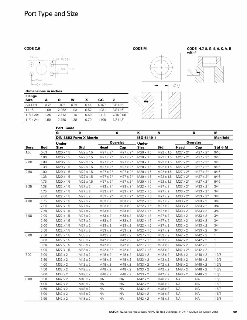
69EATON NZ Series Heavy Duty NFPA Tie Rod Cylinders V-CYTR-MC002-E2 March 2013
Port Type and Size
Bore Rod
Port CodeG 9 0 K A B MDIN 3852 Form X Metric ISO 6149-1 Manifold
Under Size Std
Oversize Under Size Std
OversizeStd Φ MHead Cap Head Cap
1.50 0.63 M20 x 1.5 M22 x 1.5 M27 x 2* M27 x 2* M20 x 1.5 M22 x 1.5 M27 x 2* M27 x 2* 9/161.00 M20 x 1.5 M22 x 1.5 M27 x 2* M27 x 2* M20 x 1.5 M22 x 1.5 M27 x 2* M27 x 2* 9/16
2.00 1.00 M20 x 1.5 M22 x 1.5 M27 x 2* M27 x 2* M20 x 1.5 M22 x 1.5 M27 x 2* M27 x 2* 9/161.38 M20 x 1.5 M22 x 1.5 M27 x 2* M27 x 2* M20 x 1.5 M22 x 1.5 M27 x 2* M27 x 2* 9/16
2.50 1.00 M20 x 1.5 M22 x 1.5 M27 x 2* M27 x 2* M20 x 1.5 M22 x 1.5 M27 x 2* M27 x 2* 9/161.38 M20 x 1.5 M22 x 1.5 M27 x 2* M27 x 2* M20 x 1.5 M22 x 1.5 M27 x 2* M27 x 2* 9/161.75 M20 x 1.5 M22 x 1.5 M27 x 2* M27 x 2* M20 x 1.5 M22 x 1.5 M27 x 2* M27 x 2* 9/16
3.25 1.38 M22 x 1.5 M27 x 2 M33 x 2* M33 x 2* M22 x 1.5 M27 x 2 M33 x 2* M33 x 2* 3/4.1.75 M22 x 1.5 M27 x 2 M33 x 2* M33 x 2* M22 x 1.5 M27 x 2 M33 x 2* M33 x 2* 3/4.2.00 M22 x 1.5 M27 x 2 M33 x 2* M33 x 2* M22 x 1.5 M27 x 2 M33 x 2* M33 x 2* 3/4.
4..00 1.75 M22 x 1.5 M27 x 2 M33 x 2 M33 x 2 M22 x 1.5 M27 x 2 M33 x 2 M33 x 2 3/4.2.00 M22 x 1.5 M27 x 2 M33 x 2 M33 x 2 M22 x 1.5 M27 x 2 M33 x 2 M33 x 2 3/4.2.50 M22 x 1.5 M27 x 2 M33 x 2 M33 x 2 M22 x 1.5 M27 x 2 M33 x 2 M33 x 2 3/4.
5.00 2.00 M22 x 1.5 M27 x 2 M33 x 2 M33 x 2 M22 x 1.5 M27 x 2 M33 x 2 M33 x 2 3/4.2.50 M22 x 1.5 M27 x 2 M33 x 2 M33 x 2 M22 x 1.5 M27 x 2 M33 x 2 M33 x 2 3/4.3.00 M22 x 1.5 M27 x 2 M33 x 2 M33 x 2 M22 x 1.5 M27 x 2 M33 x 2 M33 x 2 3/4.3.50 M22 x 1.5 M27 x 2 M33 x 2 M33 x 2 M22 x 1.5 M27 x 2 M33 x 2 M33 x 2 3/4.
6.00 2.50 M27 x 1.5 M33 x 2 M4.2 x 2 M4.2 x 2 M27 x 1.5 M33 x 2 M4.2 x 2 M4.2 x 2 13.00 M27 x 1.5 M33 x 2 M4.2 x 2 M4.2 x 2 M27 x 1.5 M33 x 2 M4.2 x 2 M4.2 x 2 13.50 M27 x 1.5 M33 x 2 M4.2 x 2 M4.2 x 2 M27 x 1.5 M33 x 2 M4.2 x 2 M4.2 x 2 14..00 M27 x 1.5 M33 x 2 M4.2 x 2* M4.2 x 2 M27 x 1.5 M33 x 2 M4.2 x 2* M4.2 x 2 1
7.00 3.00 M33 x 2 M4.2 x 2 M4.8 x 2 M4.8 x 2 M33 x 2 M4.2 x 2 M4.8 x 2 M4.8 x 2 1 3/83.50 M33 x 2 M4.2 x 2 M4.8 x 2 M4.8 x 2 M33 x 2 M4.2 x 2 M4.8 x 2 M4.8 x 2 1 3/84..00 M33 x 2 M4.2 x 2 M4.8 x 2 M4.8 x 2 M33 x 2 M4.2 x 2 M4.8 x 2 M4.8 x 2 1 3/84..50 M33 x 2 M4.2 x 2 M4.8 x 2 M4.8 x 2 M33 x 2 M4.2 x 2 M4.8 x 2 M4.8 x 2 1 3/85.00 M33 x 2 M4.2 x 2 M4.8 x 2 M4.8 x 2 M33 x 2 M4.2 x 2 M4.8 x 2 M4.8 x 2 1 3/8
8.00 3.50 M4.2 x 2 M4.8 x 2 NA NA M4.2 x 2 M4.8 x 2 NA NA 1 5/84..00 M4.2 x 2 M4.8 x 2 NA NA M4.2 x 2 M4.8 x 2 NA NA 1 5/84..50 M4.2 x 2 M4.8 x 2 NA NA M4.2 x 2 M4.8 x 2 NA NA 1 5/85.00 M4.2 x 2 M4.8 x 2 NA NA M4.2 x 2 M4.8 x 2 NA NA 1 5/85.50 M4.2 x 2 M4.8 x 2 NA NA M4.2 x 2 M4.8 x 2 NA NA 1 5/8
Dimensions in inchesFlangeSize A Q W X GG Z3/4. (-12) 0.75 1.875 0.94. 0.4.4. 0.875 3/8 (-16)
1 (-16) 1.00 2.062 1.03 0.52 1.031 3/8 (-16)
11/4. (-20) 1.25 2.312 1.16 0.59 1.118 7/16 (-14.)
11/2 (-24.) 1.50 2.750 1.38 0.70 1.4.06 1/2 (-13)
CODE C,6 CODE H,7, 8, G, 9, 0, K, A, B with*
CODE M

EATON NZ Series Heavy Duty NFPA Tie Rod Cylinders V-CYTR-MC002-E2 March 201370
Port Selections
Use this table to determine which bore diameter, rod diameter and port combina-tion will provide the piston velocity required for your application.
Bore∅in
Rod∅in
Fluid Required per Inch of stroke
Port Codes 1,5,6,9 & A
Port Codes 2,4,0 & B
Port Code 3
Port Code 7
Port Code 8
Flow(gpm)
Piston Velocity(In/sec)
Flow(gpm)
Piston Velocity(In/sec)
Flow(gpm)
Piston Velocity(In/sec)
Flow(gpm)
Piston Velocity(In/sec)
Flow(gpm)
Piston Velocity(In/sec)(gal) (in3)
1.50 Cap 0.008 1.767 6.0 13.1 9.2 20.0 6.0 13.1 3.4. 7.4. 9.2 20.00.63 0.006 1.4.60 6.0 15.8 9.2 24..3 6.0 15.8 3.4. 9.0 9.2 24..31.00 0.004. 0.982 6.0 23.5 9.2 36.1 6.0 23.5 3.4. 13.3 9.2 36.1
2.00 Cap 0.014. 3.14.2 6.0 7.4. 9.2 11.3 6.0 7.4. 3.4. 4..2 9.2 11.31.00 0.010 2.356 6.0 9.8 9.2 15.0 6.0 9.8 3.4. 5.6 9.2 15.01.38 0.007 1.657 6.0 13.9 9.2 21.4. 6.0 13.9 3.4. 7.9 9.2 21.4.
2.50 Cap 0.021 4..909 6.0 4..7 9.2 7.2 6.0 4..7 3.4. 2.7 9.2 7.21.00 0.018 4..123 6.0 5.6 9.2 8.6 6.0 5.6 3.4. 3.2 9.2 8.61.38 0.015 3.4.24. 6.0 6.7 9.2 10.3 6.0 6.7 3.4. 3.8 9.2 10.31.75 0.011 2.503 6.0 9.2 9.2 14..1 6.0 9.2 3.4. 5.2 9.2 14..1
3.25 Cap 0.036 8.296 14..5 6.7 20.2 9.4. 14..5 6.7 9.2 4..3 27.9 12.91.38 0.029 6.811 14..5 8.2 20.2 11.4. 14..5 8.2 9.2 5.2 27.9 15.81.75 0.026 5.891 14..5 9.5 20.2 13.2 14..5 9.5 9.2 6.0 27.9 18.22.00 0.022 5.154. 14..5 10.8 20.2 15.1 14..5 10.8 9.2 6.9 27.9 20.8
4..00 Cap 0.054. 12.566 14..5 4..4. 20.2 6.2 14..5 4..4. 9.2 2.8 27.9 8.51.75 0.04.4. 10.161 14..5 5.5 20.2 7.7 14..5 5.5 9.2 3.5 27.9 10.62.00 0.04.1 9.4.25 14..5 5.9 20.2 8.3 14..5 5.9 9.2 3.8 27.9 11.4.2.50 0.033 7.658 14..5 7.3 20.2 10.2 14..5 7.3 9.2 4..6 27.9 14..0
5.00 Cap 0.085 19.635 14..5 2.8 20.2 4..0 14..5 2.8 9.2 1.8 27.9 5.52.00 0.071 16.4.93 14..5 3.4. 20.2 4..7 14..5 3.4. 9.2 2.1 27.9 6.52.50 0.064. 14..726 14..5 3.8 20.2 5.3 14..5 3.8 9.2 2.4. 27.9 7.33.00 0.054. 12.566 14..5 4..4. 20.2 6.2 14..5 4..4. 9.2 2.8 27.9 8.53.50 0.04.3 10.014. 14..5 5.6 20.2 7.8 14..5 5.6 9.2 3.5 27.9 10.7
6.00 Cap 0.122 28.274. 27.9 3.8 4.5.5 6.2 27.9 3.8 14..5 2.0 4.5.5 6.22.50 0.101 23.366 27.9 4..6 4.5.5 7.5 27.9 4..6 14..5 2.4. 4.5.5 7.53.00 0.092 21.206 27.9 5.1 4.5.5 8.3 27.9 5.1 14..5 2.6 4.5.5 8.33.50 0.081 18.653 27.9 5.8 4.5.5 9.4. 27.9 5.8 14..5 3.0 4.5.5 9.4.4..00 0.068 15.708 27.9 6.8 4.5.5 11.2 27.9 6.8 14..5 3.6 4.5.5 11.2
7.00 Cap 0.167 38.4.85 4.5.5 4..6 67.4. 6.7 4.5.5 4..6 27.9 2.8 67.4. 6.73.00 0.136 31.4.16 4.5.5 5.6 67.4. 8.3 4.5.5 5.6 27.9 3.4. 67.4. 8.33.50 0.125 28.863 4.5.5 6.1 67.4. 9.0 4.5.5 6.1 27.9 3.7 67.4. 9.04..00 0.112 25.918 4.5.5 6.8 67.4. 10.0 4.5.5 6.8 27.9 4..1 67.4. 10.04..50 0.098 22.580 4.5.5 7.8 67.4. 11.5 4.5.5 7.8 27.9 4..8 67.4. 11.55.00 0.082 18.850 4.5.5 9.3 67.4. 13.8 4.5.5 9.3 27.9 5.7 67.4. 13.8
8.00 Cap 0.218 50.266 67.4. 5.2 4.5.5 3.5 4.5.5 3.5 27.9 2.1 67.4. 5.23.50 0.176 4.0.64.4. 67.4. 6.4. 4.5.5 4..3 4.5.5 4..3 27.9 2.6 67.4. 6.4.4..00 0.163 37.699 67.4. 6.9 4.5.5 4..6 4.5.5 4..6 27.9 2.8 67.4. 6.94..50 0.14.9 34..361 67.4. 7.6 4.5.5 5.1 4.5.5 5.1 27.9 3.1 67.4. 7.65.00 0.133 30.631 67.4. 8.5 4.5.5 5.7 4.5.5 5.7 27.9 3.5 67.4. 8.55.50 0.115 26.507 67.4. 9.8 4.5.5 6.6 4.5.5 6.6 27.9 4..1 67.4. 9.8
Note : Under size port velocities are not shown

71EATON NZ Series Heavy Duty NFPA Tie Rod Cylinders V-CYTR-MC002-E2 March 2013
Port Locations
Port locations are identified by viewing the cylinder from the head end (or from the mounting end of double rod cylinders). The location num-
bers are shown here.
Certain Port locations can-not be specified with some mounting styles. The table
below indicates which of the head and cap port locations are available for each Series NZ mounting style.
Mounting Style code Description
Head location Cap location
1 2 3 4 1 2 3 4 5 01 Side Lug A W A W A W A W A 02 Side Tapped A A N A A A N A A 03 End Lug Mount A A N A A A N A A 04. Keyed Side Lug A W A W A W A W A 05 Keyed Tapped A A N A A A N A A 07 Head Rectangular Flange A W A W A A A A A 08 Head Square Flange W W W W A A A A A 09 Head Rectangular A A A A A A A A A 10 Clevis A A A A A A A A N 11 Spherical Bushing A A A A A A A A N 12 Cap Rectangular Flange A A A A A W A W N 13 Cap Square Flange A A A A W W W W N 14. Cap Rectangular A A A A A A A A N 15 Intermediate Trunnion A A A A A A A A A 16 Cap Trunnion A A A A A N A N A 17 Head Trunnion A N A N A A A A A 19 Centerline Lug A N A N A N A N A 21 Cap End Extended Tie Rod A A A A A A A A A 22 Head End Extended Tie Rod A A A A A A A A A 23 Both Ends Extended Tie Rod A A A A A A A A A 24. No Mount A A A A A A A A A 25 Double Rod, Side Lug A A A A 26 Double Rod, Tapped A A N A 27 Double Rod, End Lug A A N A 28 Double Rod, Keyed Side Lug A W A W 29 Double Rod, Keyed Tapped A A N A 31 Double Rod, Rectangular Flange A W A W 32 Double Rod, Square Flange W W W W 33 Double Rod, Head Rectangular A A A A 34. Double Rod, Intermediate Trunnion A A A A 35 Double Rod, Head Trunnion A N A N 37 Double Rod, Centerline Lug A N A N 39 Double Rod, Extended Tie Rod A A A A 4.0 Double Rod, Both Ends Extended Tie Rod A A A A 4.1 Double Rod, No Mount A A A A 4.7 Cap Fixed Eye A A A A A A A A N 4.8 Cap Detachable Eye A A A A A A A A N 50 Cap Detachable Clevis A A A A A A A A N
A - Available N - Not available W - Port is available without port Boss only Refer Page 68 for port Boss requirements, refer Page 74. for switch availability
Bore J D
1.50 0.625 0.22
2.00 0.812 0.38
2.50 1.188 0.7
3.25 1.188 0.4.4.
4..00 1.562 0.66
5.00 1.562 0.062
6.00 2.00 -
7.00 2.312 0.31
8.00 2.312 -

EATON NZ Series Heavy Duty NFPA Tie Rod Cylinders V-CYTR-MC002-E2 March 201372
Sealing system
Four different sealing sys-tems are available in Series NZ cylinders.
Determine the correct seal code for your application, then enter it as item 8 in the model code.
Code Fluid Temperature (°F) Max. Speed (ft/s) Application
N Mineral oil, petroleum base –31 to 176 2.25 Normal, typical industrial
Automotive transmission fluid
L Mineral oil –31 to 24.8 15 Low friction servo
Water glycol (HFC)Oil-in-water emulsions (HFA) Water-in-oil emulsions (HFB)
50 to 158 3 Fire retardant fluids
T Mineral oil –13 to 392 15 High temperature
Phosphate esters, petroleum oil blendsFyrquel 220, 550, 1000 Hought-O-Safe 134.0 Pydraul 200, 230C, 280, 312C, 54.0C, A200
32 to 392 15 Fire retardant fluids
C Mineral oil, petroleum base –31 to 176 2.25 Normal, typical industrial
Automotive transmission fluid
Rod Seal Configuration
Piston Seal Configuration
N and C sealing Option L and T sealing Option
N, L and T Seal Option C Seal Option

73EATON NZ Series Heavy Duty NFPA Tie Rod Cylinders V-CYTR-MC002-E2 March 2013
Gland Drain Option Gland drains are primar-ily used for long stroke cylinders (over 30 inches) and when extended speed exceeds retract speed.
The gland drain is used to return any accumulated fluid, between the rod seal and wiper, to tank. This is used in servo applications, for ultra-low leakage require-ments, or for remote visual monitoring of rod seal leak-age for preventive mainte-nance purposes.
Air Bleed OptionUsually cylinders will bleed themselves of air when ports are vertical, on top. Bleed ports are often desir-able to remove entrapped air, when the ports are on the bottom. High perfor-mance and high speed or heavy load applications are a few examples where air bleeds are desirable.
Gland drains/Air bleeds

EATON NZ Series Heavy Duty NFPA Tie Rod Cylinders V-CYTR-MC002-E2 March 201374
Technical Data Proximity Switches
Proximity switches for series NZ cylinder are inductive type switches with sensing probe that “looks” at the cushion collar or button to provide extended or retract-ed indication. Since the probe is inside the cylinder, harsh external environments don’t affect sensing. The 2-wire circuit will operate on AC or DC and works as
reliably as a programmable controller.Proximity switches will meet UL requirements for 3000-psi (210 bar) hydraulic cylinder.
Switch will allow 304.° rota-tions. Short Circuit protec-tion is standard feature on Proximity proximity switch. SCP protects the switch from shorts in load or line. Upon sensing short condi-
tion, the switch assumes a non-conducting mode. The fault condition must be removed and power turned off in order to reset the switch.
This feature prevents unin-tended automatic restarts. The switch indicated when it is in SCP mode by flashing both leads.
Torque ¼-20 mounting screws to 15 ft-lb (20 Nm)
BORE ROD“D” Max.
“D” Max.
“D” Max.
09 mounts Pos. 2 & 4
14 mounts Pos. 2 & 4
1.50 0.63 2.99 4..03 2.99
1.00 3.12 4..16 3.12
CAP 2.99 2.99 3.80
2.00 1.00 3.37 5.00 3.37
1.38 3.30 4..34. 3.30
CAP 3.08 3.08 4..73
2.50 1.00 3.35 5.00 3.35
1.38 3.53 5.15 3.53
1.75 3.4.9 4..53 3.4.9
CAP 3.92 3.92 4..73
3.25 1.38 4..4.0 5.22 4..4.0
1.75 4..59 5.4.0 4..59
2.00 3.82 5.4.7 3.82
CAP 4..03 4..03 5.75
4..00 1.75 4..59 5.4.1 4..59
2.00 4..78 5.59 4..78
2.50 4..07 5.72 4..07
CAP 4..84. 4..84. 5.74.
5.00 2.00 5.59 6.4.9 5.59
2.50 5.03 6.74. 5.03
3.00 5.28 6.99 5.28
3.50 5.4.0 7.12 5.4.0
CAP 5.03 5.03 6.72
6.00 2.50 5.84. 7.53 5.84.
3.00 6.09 7.78 6.09
3.50 5.38 7.11 5.38
4..00 5.66 7.37 5.66
CAP 6.18 6.18 7.4.1
7.00 3.00 6.09 8.22 6.09
3.50 6.34. 8.03 6.34.
4..00 6.4.7 8.15 6.4.7
4..50 6.03 8.53 6.03
5.00 6.19 8.68 6.19
CAP 6.18 6.18 NA
8.00 3.50 6.32 NA 6.32
4..00 6.4.7 8.60 6.4.7
4..50 6.84. 8.97 6.84.
5.00 7.00 8.68 7.00
5.50 6.4.7 8.96 6.4.7
CAP 6.21 6.21 NA
Balluff
Pressure 3000 PSI
Sensing Range 0.08 in ± 10 %
Sensing distance from End of stroke
0.25” - 0.38” stroke to go
Operating temperature range -13° to +158° F
Repeatability 0.001 in
Switching differential ≤ 15%
Supply Voltage 20 - 250 V AC / DC
Voltage drop ≤ 6 V
Load Current capacity @ 25° C 5-4.00 mA
Inrush current ≤ 3A (t ≤ 20ms)
Indicating LED’s (Standard) 1 lit:Power on non-conducting2 lit: Target present(both flashing = SCP mode )
Note : NA - Not availableProximity switch for 1.50” at postion 2 & 4 is not available for 07Mount at Head end, 12 Mount at Cap endProximity Switch for “1.50“ is unavailable for 08 Mount at Head end, 13 Mount at Cap endProximity Switch for “7.00 & 8.00” is unavailable for 14 Mount at Cap end
D2.57
1.89

75EATON NZ Series Heavy Duty NFPA Tie Rod Cylinders V-CYTR-MC002-E2 March 2013
38 EATON Mill Type Cylinder Series EM E-CYMG-MC001-E March 2010
Thread-In Style Transducers
Industry standard transducer type for industrial cylinder applica-tions. Cylinders can be manufactured prepared for transducer or with transducer already installed.
Two different protective cover options are available for rugged environments protect the electronics.
Transducer Cover
Rugged aluminum casting cover protects the transducer from minor wear and tear, yet is easily removable to service the trans-ducer.
False Stage Cover
Transducer is protected by a tie-rod cylinder body and end cap for the best protection short of the encapsulated HLT II design. Utilize this design when you need heavy duty protection for the transducer, yet need output options not available in the HLT II.
False Stage Cover Mount
Heavy duty false stage covers that are suitable for rear mounts (clevis, spherical bearing, etc.) are available. Utilize this design when you need heavy duty protection for the transducer in a rear mount cylinder, yet need output options not available in the HLT II.
Eaton HLT II
The Eaton HLT II linear displacement transducers are precise, durable, cost-effective measurement devices. Well protected within the core of the cylinder, the HLT II not only measures the position of the moving elements of an actuation system, but also remains untouched, and unaffected by even the harshest elements. HLT II also is an ideal choice, with it’s compact design, when overall cylinder length is a concern. The innovative encap-sulated design and engineering along with the rugged construc-tion of Eaton HLT II transducers guarantee the best reliability, precision and durability in even the toughest industrial environ-ment.
Custom Transducers
Eaton has been an industry pioneer incorporating positioning systems into industrial cylinders, and can find design system for any application. If a specific type of system is required and not listed here, Eaton can create custom cylinders incorporating your needs.
Application/Engineering DataTransducer Options
Transducer
Hard Aluminum CoverSteel Body
Permanent MagnetThreaded Type
TransducerConnector
Permanent Magnet
Connector
Analog Or DigitalHLT II ElectronicsModule
A complete line of precision cylinder position sensing and feed-back devices are available. These packaged cylinder systems can handle virtually any application requiring feedback throughout
the cylinder stroke —pneumatic or hydraulic, large or small bore, long or short strokes, with or without velocity monitoring — with resolutions of ± 0.001” or better.
SC
SBG
CYLINDER ASSEMBLY
MVT
NONE
01-07-2013
LIGHT OIL
ACES 16P13
B
A ENGINEERING RELEASE 01-07-2013
SBG
REVIEWED FOR CLASSIFICATION OF CHARACTERISTICS PER ESP-042
NZ09C-CATALOG
D
C
B
AA
B
C
D
12345678
8 7 6 5 4 3 2 1
E
F
E
F
Drawn By:
Checked By:
Scale:
Date:
CUSTOMER:
Dwg. No.:
Dwg. Title:
2425 W. Michigan Ave. - Jackson, MI 49202
DISTRIBUTOR:
REV.
Finish:
Finish Spec.:
Third Angle Projection
REV.NO. REVISION/DESCRIPTION DATE BY
EATON CORPORATION-CONFIDENTIAL AND PROPRIETARYNOTICE TO PERSONS RECEIVING THIS DRAWING AND/OR TECHNICAL INFORMATIONTHIS DOCUMENT, INCLUDING THE DRAWING AND INFORMATION CONTAINED THEREON, IS CONFIDENTIAL AND IS THE EXCLUSIVE PROPERTY OFEATON CORPORATION, AND IS MERELY ON LOAN AND SUBJECT TO RECALL BY EATON AT ANY TIME. BY TAKING POSSESSION OF THIS DOCUMENT,THE RECIPIENT ACKNOWLEDGES AND AGREES THAT THIS DOCUMENT CANNOT BE USED IN ANY MANNER ADVERSE TO THE INTERESTS OF EATON,AND THAT NO PORTION OF THIS DOCUMENT MAY BE COPIED OR OTHERWISE REPRODUCED WITHOUT THE PRIOR WRITTEN CONSENT OF EATON.IN THE CASE OF CONFLICTING CONTRACTUAL PROVISIONS, THIS NOTICE SHALL GOVERN THE STATUS OF THIS DOCUMENT.© 2008 Eaton Corporation - All Rights Reserved.
A wide variety of precision cylinder position sensing and feedback devices are available. These packaged cylinder sys-tems can handle virtually any application requiring feedback throughout the cylinder stroke with or without velocity mon-itoring and with resolutions of ± 0.001 or better. Cylinders can be manufactured prepared for transducer or with trans-ducer already installed.
Two different protective cover options are available for rug-ged environments to protect the electronics.
Transducer Cover
Rugged aluminum casting cover protects the transducer form minor wear and tear, yet is easily removable to service the transducer.
False Stage Cover
Transducer is protected by a tie-rod cylinder body and end cap for the best protection short of the encapsulated HLT II design. Utilize this design when you need heavy duty pro-tection for the transducer, yet need output options not avail-able in the HLT II.
Eaton HLT II
The Eaton HLT II is a linear displacement transducers are precise, durable, cost-effective measurement devices. Well protected within the core of the cylinder, the HLT II not only measures the position of the moving elements of the cylin-der, but also remains untouched, and unaffected by even the harshest elements. HLT II also is an ideal choice, with its compact design, when overall cylinder length is a concern. The innovative encapsulated design and engineering along with the rugged construction of Eaton HLT II transducer guarantee the best reliability, precision and durability in even the toughest industrial environment.
Additional Probe Options
Eaton has years of experience providing cylinders with a variety of transducer feedback options. From the common mangetostrictive type transducers to solid state transduc-ers, Eaton can provide a solution for your feedback needs regardless of application or condition. Eaton can also pro-vide a cylinder “prepared” for a transducer if you prefer to provide your own feedback. Please contact your Eaton representative with your requirements and we can provide a cylinder solution.
Application Engineering Data Transducer Options
13EATON Electronic Feedback Cylinders E-HYOV-TM003-E June 2011
Transducer Specifications Temposonics L Series
Noncontact Transducer
Hydro-Line utilizes MTS Temposonics® feedback technology, a magnetostriction device. Selection of feedback output should be matched to the control systems to ensure optimum performance of the positioning system.
Permanent Magnet Assembly Transducer Wand
Analog or DigitalTransducer
2” NullStroke2.5”Deadband
Characteristics Description/Specification
SupplyVoltage Strokes<60”;+13.5to26.4Vdc(±0%);Strokes>60”;+24Vdc(±10%)Current Draw Analog: 120 mA Digital: 100 mA TypicalNull Space Null space is 2” unless otherwise notedDead Band Dead band is 2.5” from tip of transducerDisplacement Range Analog: 1” to 78” stroke Digital: 1” to 120” strokeHead Enclosure Aluminum die-cast head, IP 67 stainless rod and flangeNon-Linearity ± 0.02% or ± 0.0002”, whichever is greaterRepeatability ±0.001% of full stroke or ± 0.0001”, whichever is greaterHysteresis 0.0008” maximumResolution Analog: Infinite Digital:1÷[gradientxCrystalFreg.(mHz)xcirculation];Maxresolution:0.00025”EMC Test* DIN EN 50081-1 (Emissions) DIN EN 50082-2 (Immunity)Operating Temperature -40°F to 158°FOperating Pressure ** 3000 psi continuous, 5000 psi static, 10,000 psi spikeShock Rating 100g (single hit) / IEC standard 68-2-27 (survivability)UpdateTime Analog:<1ms Digital:ResolutionandStrokedependent;Minimum=[Stroke(specifiedininches)+3]x9.1μsOutput (absolute) Analog: Voltage and current output available – see L Series ordering guide Analog Adjustability: Field adjustable zero and span to 5% of active stroke Digital:Pulse-widthmodulated(upto15recirculations);Start/Stop(RS422compatible)Vibration Rating 5g/10-150 Hz/IEC standard 68-2-6Maximum Cable Length Analog: 50 feet Digital: PWM output, 150 feet RS422 Start/Stop 500 feet
Specifications
* EMC test specification does not include sensor with the RB connection style. Sensor with RB connection style meets the following standard: DIN EN 50081-2 (emissions) and DIN EN 50082-1 (immunity). ** Compare these specifications to cylinder specifications. Use the proper limiting specification. Temposonics® is a registered trademark of MTS System Corporation
12 EATON Electronic Feedback Cylinders E-HYOV-TM003-E June 2011
How to Order an HLT II
Symbol Feature Description
1 Sensor Type Hydro-Line In-Cylinder Sensor (HLT II)Analog Output
A 0 to +10 VdcgnitcA esreveR ,cdV 01+ ot 0B
Am 02 ot 4CgnitcA esreveR ,Am 02 ot 4D
Am 02 ot 0EgnitcA esreveR ,Am 02 ot 0F
cdV 01+ ot 01-GgnitcA esreveR ,cdV 01+ ot 01-H
cdV 5+ ot 5-JgnitcA esreveR cdV 5+ ot 5-K
Digital OutputP PWM (Pulse Width Modulation) -specify internal or external interrogation and 2, 4, 6 or 8 recirculationsR RS422 (Start/Stop leading edge active) S RS422 (Start/Stop trailing edge active)1 24 Vdc (±20%) 2 ± 15 Vdc (±2%)3 ±12 Vdc (±2%)A Straight Micro Change Cable Assembly, 6 FootB Straight Micro Change Cable Assembly,12 FootC Straight Micro Change Cable Assembly, 20 FootD Right Angle Micro Change Cable Assembly, 6 FootE Right Angle Micro Change Cable Assembly, 12 FootF Right Angle Micro Change Cable Assembly, 20 FootJ Straight Micro Change Cable Assembly, Special Length Cable
(Electronic Feedback Application Data Sheet Required)K Right Angle Micro Change Cable Assembly, Special Length Cable
(Electronic Feedback Application Data Sheet Required)N No Cable AssemblyX Special Connector and Cable (Electronic Feedback Application Data Sheet Required)1 Position 12 Position 2
3 noitisoP34 noitisoP4
X Special Location (Electronic Feedback Application Data Sheet Required)
H Supplier Supplied by Hydro-Line
0 No Manifold Block1 Mounting Pattern 12 Mounting Pattern 23 DO5 Mounting Pattern4 DO3 Mounting PatternX Special Valve Patterns (Electronic Feedback Application Data Sheet Required)
N Sensor Cover Not applicable
1-A-1-A-2-N-0-H
OutputOptionsReferencePage 18
Mating CableOptionsSee below
ConnectorLocationReference
Page 20 or 40
Valve Manifold
StyleReferencePage 42
1.60"
2.50"
Molded Cable Assembly
Straight CableAssembly
90° CableAssembly
NOTE: 90° CableAssembly PositionNot Adjustable
Power RequirementReference
Page 8
Analog or Digital HLT II Electronics Module
Nonferrous Plug Assembly
Permanent Magnet
Integral or Nonintegral Cover
Six Pin Mirco-Change Connector
False Stage Cover
Rugged Aluminum Cover
Typical Probe Design Threaded in Cap
HLT II

EATON NZ Series Heavy Duty NFPA Tie Rod Cylinders V-CYTR-MC002-E2 March 201376
Eaton cylinders can be specified to include hydraulic mani-folds and plumbing to simplify the integration of the cylinder with a control valve. Eaton offers standard hydraulic mani-fold options for valve interfaces of CETOP D03, D05 and SM4.-20. Other manifolds can be designed as a special and incorporated with or without feedback.
Customer Requirements
Eaton has been an industry pioneer incorporating positioning systems into industrial cylinders, and can design systems for any application. If a specific type of system is required and not covered here, we can work with you to create a cyl-inder configuration incorporating your needs.
Application/Engineering Data Manifold Options

77EATON NZ Series Heavy Duty NFPA Tie Rod Cylinders V-CYTR-MC002-E2 March 2013
Technical Data
Stop Tubes
Stop tubes are located be-tween the piston and the rod shoulder on the head end of the cylinder. Bearing loading is reduced by separating the piston and the rod bushing. Bearing wear and tendency to buckle is reduced.To determine if a stop tube is required and the length of stop tube needed, use the following procedure:
Determine the value of D with the piston rod in the fully extended position. If the value of D is under 4.0”, no stop tube is needed.
If D is greater than 4.0”, one inch of stop tube is recom-mended for each 10”, or frac-tion thereof, beyond 4.0”.
Special Note
When specifying stroke and stop tube lengths, please
include net working stroke plus stop tube length.
Rod Bushing
Stop Tube Piston
S
T
S
T
S
T
S
T
D D D
S
T
S
T
Unsupported Rod End
D = SD = 4S
Supported Rod End
D = 0.5S
Firmly Guided Rod End
D = 4S
Unsupported Rod End
noinnurT daeH noinnurT etaidemretnInoinnurT ro sivelC paCD = 0.5S
Firmly Guided Rod End
D = S
Supported Rod End
Stop Tubes
There are two stop tube designs depending on the length required. Design AThe standard stop tube design for lengths under 10”.
Design BThe standard stop tube design for lengths over 10”. Note that the piston’s effective bearing area is doubled, in addition to gaining the normal increased minimum distance between bearing points.

EATON NZ Series Heavy Duty NFPA Tie Rod Cylinders V-CYTR-MC002-E2 March 201378
Technical Data
Tie rod Spacers and Center supports
A tie rod spacer or center support should be applied when the stroke length exceeds 20 times the bore diameter. Tie rod spacer
Tie rod spacers and center supports are used to improve the structural rigidity of long
stroke tie rod cylinders. The spacers have through holes for the tie rods and are held in place on the cylinder barrel with a small tack weld or set screw. The spacer keeps the tie rod in the proper position around the centerline of the cylinder and acts much like a truss in preventing excessive deflection in a long stroke cyl-inder that is not rigidly mount-ed (clevis mount, etc.).
THROUGH TIE RODS
.XXX = +/- 0.125ANGLES = +/- 5<MOD-DEG>
METRIC TOLERANCES
Dimensioning per ANSI Y14.5
DWG. TITLE:
MATERIAL:
DWG. NO.:
Drawn By:
Checked By:
Scale:
Date:
MAT'L SPEC.:
UNLESS OTHERWISE SPECIFIEDDECIMAL TOLERANCES
Work to dimensions & DO NOT SCALE PRINT
REV.
NO.
FINISH:
used to manufacture anything shown hereon without the expressed written consent of Eaton Corporation.
.XX = +/- 0.25
Eaton Corporation claims proprietary rights in the information disclosed hereon. This document
.XX = +/- .010
NOTICE TO PERSONS RECEIVING THIS DRAWING AND/OR TECHNICAL INFORMATION
FINISH SPEC.:
REVISION/DESCRIPTION
.X = +/- .06
is issued in confidence and is property of Eaton Corporation. This document is not to be reproduced orDATE
THIRD ANGLE PROJECTION
.XXX = +/- .005
.X = +/- 0.8
REV. BY
All machined surfaces to be 125 RMS unless notedRemove all burrsBreak all corners .01/.02 (0.25 MM) R or chamfer
145, Off Mumbai - Pune Rd.Pune, Maharashtra 411 018
TAPPED TIE RODS
ACES 16P13
X XA
< Part Number Here >
< Title Here >
XXX
XXX
XXX
XX-XX-XX
A
LIGHT OIL
ISSUED
Tie rod center support
The center support has side mounting lugs similar to side lug mount heads and serves as an additional mounting location. The tie rods are threaded into the center support and it becomes a load-carrying component of the cylinder assembly.
The exact location of the tie rod center support is gener-ally optional, which greatly increases the flexibility in mounting a long stroke cylinder.
THROUGH TIE RODS
.XXX = +/- 0.125ANGLES = +/- 5<MOD-DEG>
METRIC TOLERANCES
Dimensioning per ANSI Y14.5
DWG. TITLE:
MATERIAL:
DWG. NO.:
Drawn By:
Checked By:
Scale:
Date:
MAT'L SPEC.:
UNLESS OTHERWISE SPECIFIEDDECIMAL TOLERANCES
Work to dimensions & DO NOT SCALE PRINT
REV.
NO.
FINISH:
used to manufacture anything shown hereon without the expressed written consent of Eaton Corporation.
.XX = +/- 0.25
Eaton Corporation claims proprietary rights in the information disclosed hereon. This document
.XX = +/- .010
NOTICE TO PERSONS RECEIVING THIS DRAWING AND/OR TECHNICAL INFORMATION
FINISH SPEC.:
REVISION/DESCRIPTION
.X = +/- .06
is issued in confidence and is property of Eaton Corporation. This document is not to be reproduced orDATE
THIRD ANGLE PROJECTION
.XXX = +/- .005
.X = +/- 0.8
REV. BY
All machined surfaces to be 125 RMS unless notedRemove all burrsBreak all corners .01/.02 (0.25 MM) R or chamfer
145, Off Mumbai - Pune Rd.Pune, Maharashtra 411 018
TAPPED TIE RODS
ACES 16P13
X XA
< Part Number Here >
< Title Here >
XXX
XXX
XXX
XX-XX-XX
A
LIGHT OIL
ISSUED

79EATON NZ Series Heavy Duty NFPA Tie Rod Cylinders V-CYTR-MC002-E2 March 2013
Bore & Rod Diameter – Cylinder Size Selection
To choose the proper size of cylinder for your application, first determine the maximum push or pull force required to do the job. Then use the below table to select the cylinder that will provide that force.
Remember that force capa-bilities derieved from charts and formulas may be theroti-cally correct, but other factor must be considered. Be sure to allow for pressure drop between pump outlet and
cylinder port. Also some of a cylinder force is used up over-coming seal friction and lesser extent the inertia of the piston itself.
WARNING It is the user’s responsibility to select the correct cylinder size.
Borefin
Rodfin
Work Area(in2)
Maximum Force (lbf) At working pressure(psi)500(psi)
750(psi)
1000(psi)
1500(psi)
2000(psi)
3000(psi)
1.50 - 1.767 884. 1325 1767 2651 3534. 5301
0.625 1.4.60 730 1095 14.60 2191 2921 4.381
1 0.982 4.91 736 982 14.73 1964. 294.5
2.00 - 3.14.2 1571 2356 314.2 4.712 6283 94.25
1 2.356 1178 1767 2356 3534. 4.712 7069
1.375 1.657 828 124.3 1657 24.85 3313 4.970
2.50 - 4..909 24.54. 3682 4.909 7363 9817 14.726
1 4..123 2062 3093 4.123 6185 824.7 12370
1.375 3.4.24. 1712 2568 34.24. 5136 684.8 10272
1.75 2.503 1252 1878 2503 3755 5007 7510
3.25 - 8.296 4.14.8 6222 8296 124.4.4. 16592 24.887
1.375 6.811 34.05 5108 6811 10216 13622 204.33
1.75 5.891 294.5 4.4.18 5891 8836 11781 17672
2 5.154. 2577 3866 5154. 7731 10308 154.63
4..00 - 12.566 6283 94.25 12566 18850 25133 37699
1.75 10.161 5081 7621 10161 1524.2 20322 304.83
2 9.4.25 4.712 7069 94.25 14.137 18850 28274.
2.5 7.658 3829 574.3 7658 114.86 15315 22973
5.00 - 19.635 9817 14.726 19635 294.52 39270 58905
2 16.4.93 824.7 12370 164.93 24.74.0 32987 4.94.80
2.5 14..726 7363 1104.5 14.726 22089 294.53 4.4.179
3 12.566 6283 94.25 12566 18850 25133 37699
3.5 10.014. 5007 7510 10014. 15021 20028 3004.2
6.00 - 28.274. 14.137 21206 28274. 4.24.12 5654.9 84.823
2.5 23.366 11683 17524. 23366 3504.8 4.6731 70097
3 21.206 10603 15904. 21206 31809 4.24.12 63617
3.5 18.653 9327 13990 18653 27980 37307 55960
4. 15.708 7854. 11781 15708 23562 314.16 4.7124.
7.00 - 38.4.85 1924.2 28863 384.85 57727 76969 1154.54.
3 31.4.16 15708 23562 314.16 4.7124. 62832 94.24.8
3.5 28.863 14.4.32 2164.8 28863 4.3295 57727 86590
4. 25.918 12959 194.39 25918 38877 51836 77755
4..5 22.580 11290 16935 22580 33870 4.5161 6774.1
5 18.850 94.25 14.137 18850 28274. 37699 5654.9
8.00 - 50.266 25133 37699 50266 75398 100531 150797
3.5 4.0.64.4. 20322 304.83 4.064.4. 60967 81289 121933
4. 37.699 18850 28274. 37699 5654.9 75398 113098
4..5 34..361 17181 25771 34.361 5154.2 68723 103084.
5 30.631 15315 22973 30631 4.594.6 61261 91892
5.5 26.507 13254. 19880 26507 39761 53015 79522

EATON NZ Series Heavy Duty NFPA Tie Rod Cylinders V-CYTR-MC002-E2 March 201380
Calculation according to Euler F Safety factor, P Critical load, LbE Modulus of elasticity, 30000000 psiL Length, in
Calculation according to Jb Johnson I Moment of inertia, in^4C End condition
Fixed-Guided 2Fixed-Fixed 4Pin-Pin 1
A Rod area, in²k Radius of gyration, in
End conditions for above chartMount Condition01,09,14 Fixed-Guided10,11,15 Pin-Pin
²²
FLEIC
Pπ
=
−=
²²4²
1EkC
LSF
ASP
yy
π
≤yS
ECkL ²2 π
yS
EC
k
L ²2 π
Maximum Allowable Push Stroke(Recomended “L”)
In Push application, a cylinder acts as loaded column.
To use the side table first go to section for your mounting style. Then locate the col-umn which is closest to, but not below, your application’s operating pressure. The inter-section of operating pressure and Bore /rod size represents the allowable length (L) in full extended condition.
The maximum allowable length “L” is based on column spelling analysis only and does not consider side load-ing, stop tube requirments or oter cylinder stroke limita-tions.
For pressure above 3000 PSI Consult your local Eaton rep-resentative.
Maximum Length L (in) at Working Pressure (psi) { Length L in full extend condition}
Borefin
Rodfin
Rigid Mount (01,02,04,05,07,08,09,12,
13,14,19,21,22,23,24)Swivel Mount
(10,11,15,16,17,47,48,50)3000psi
2000psi
1500psi
1000psi
750psi
500psi
250psi
3000psi
2000psi
1500psi
1000psi
750psi
500psi
250psi
1.50 0.63 14. 19 22 27 31 38 54. 10 13 15 19 22 27 381.00 4.0 4.8 56 69 79 97 137 28 34. 4.0 4.8 56 69 97
2.00 1.00 30 36 4.2 51 59 73 103 21 26 30 36 4.2 51 731.38 56 69 79 97 112 137 194. 4.0 4.9 56 69 79 97 137
2.50 1.00 20 19 34. 4.1 4.7 58 82 14. 19 24. 29 34. 4.1 581.38 4.5 55 63 78 90 110 156 32 39 4.5 55 63 78 1101.75 73 89 103 126 14.5 178 252 51 63 73 89 103 126 178
3.25 1.38 32 4.2 4.9 60 69 85 120 23 30 35 4.2 4.9 60 851.75 56 69 79 97 112 137 194. 4.0 4.8 56 69 79 97 1372.00 73 89 103 127 14.6 179 253 52 63 73 89 103 127 179
4..00 1.75 4.3 56 64. 79 91 111 157 31 39 4.5 56 64. 79 1112.00 59 73 84. 103 119 14.5 206 4.2 51 59 73 84. 103 14.52.50 93 114. 131 161 186 227 321 66 80 93 114. 131 161 227
5.00 2.00 4.0 38 67 82 95 116 165 28 27 4.7 58 67 82 1162.50 74. 91 105 129 14.8 182 257 52 64. 74. 91 105 129 1823.00 107 131 151 185 214. 262 370 76 93 107 131 151 185 2623.50 14.5 178 206 252 291 356 504. 103 126 14.5 178 206 252 356
6.00 2.50 56 76 87 107 124. 151 214. 4.0 54. 62 76 87 107 1513.00 89 109 126 154. 178 218 308 63 77 89 109 126 154. 2183.50 121 14.8 171 210 24.2 297 4.20 86 105 121 14.8 171 210 2974..00 158 194. 224. 274. 317 388 54.8 112 137 158 194. 224. 274. 388
7.00 3.00 72 93 108 132 153 187 264. 51 66 76 93 108 132 1873.50 104. 127 14.7 180 208 254. 360 73 90 104. 127 14.7 180 254.4..00 136 166 192 235 271 332 4.70 96 118 136 166 192 235 3324..50 172 210 24.3 297 34.4. 4.21 595 121 14.9 172 210 24.3 297 4.215.00 212 260 300 367 4.24. 519 735 150 184. 212 260 300 367 519
8.00 3.50 87 111 129 157 182 223 315 62 79 91 111 129 157 2234..00 119 14.5 168 206 237 291 4.11 84. 103 119 14.5 168 206 2914..50 150 184. 213 260 301 368 521 106 130 150 184. 213 260 3685.00 186 227 262 321 371 4.54. 64.3 131 161 186 227 262 321 4.54.5.50 224. 275 317 389 4.4.9 550 778 159 194. 224. 275 317 389 550
Calculation according to Euler F Safety factor, P Critical load, LbE Modulus of elasticity, 30000000 psiL Length, in
Calculation according to Jb Johnson I Moment of inertia, in^4C End condition
Fixed-Guided 2Fixed-Fixed 4Pin-Pin 1
A Rod area, in²k Radius of gyration, in
End conditions for above chartMount Condition01,09,14 Fixed-Guided10,11,15 Pin-Pin
²²
FLEIC
Pπ
=
−=
²²4²
1EkC
LSF
ASP
yy
π
≤yS
ECkL ²2 π
yS
EC
k
L ²2 π
Rigid MountsSwivel Mounts

81EATON NZ Series Heavy Duty NFPA Tie Rod Cylinders V-CYTR-MC002-E2 March 2013
Cushions are recommended when piston speed is in excess of 20-25 feet per min-ute. Cushions decelerate the piston and rod assembly at the end of the stroke, lessen-ing the noise and shock
and increasing cylinder life. Heavy loads attached to the piston and rod assembly should be stopped by external means, such as shock absorb-ers, springs, decelerating valves, etc.
Technical Data Cushion Formulas and Factors
Force Factor ChartForce Factors (a = v2 x .001294.)
Piston Velocity
ips a
1 0.001
2 0.005
3 0.012
4. 0.021
5 0.032
6 0.04.7
7 0.063
8 0.083
9 0.105
10 0.129
11 0.157
12 0.186
13 0.219
14. 0.254.
15 0.291
16 0.331
17 0.374.
18 0.4.19
19 0.4.67
20 0.518
21 0.571
22 0.626
23 0.685
24. 0.74.5
25 0.809
(continued)
General Formulas Horizontal motion Facc or Fdec = W x a/s
Vertical motion, decelerating downward or accelerating upward Facc or Fdec = (W x a/s) + W
Vertical motion, deceleratingupward or accelerating downward Facc or Fdec = (W x a/s) – W
Frictional force Ff = u x W
Total cushioning force Ft = Facc or Fdec + Fp ± Ff
(+ Ff if load accelerating, — Ff if load decelerating)
Contained pressure Pc = Ft/Acc or Ft/Ahc
Use the information below, along with the examples on page 83 to determine if stan-dard cushioning is sufficient for your application.
Force Factor Terminology
Acceleration andDeceleration Forces
The a force factors shownare used to determine theforces required to accelerateor decelerate a weightthrough a given distance, s(Refer to Force Factor Chart).
• If the motion of the load ishorizontal, use the generalformula Facc or Fdec = W x a/s.
• If the motion of the load isvertical and is being deceler-ated downward or accelerat-ed upward, use the general formula Facc or Fdec = (W x a/s) + W.
• If the motion of the load isvertical and is being deceler-ated upward or accelerated downward, use the general formula Facc or Fdec = (W x a/s) - W.
• Friction due to load motionaffects Ft. Add Ff to Ft if the load is accelerating. Sub-tract Ff from Ft if the load is decelerating.
• Cylinder friction is negligible.
Note
The contained cushioning pressure must not exceed 5000 psi. If the standard cush-ion results in a too high pres-sure, then a longer cushion spud must be specified.

EATON NZ Series Heavy Duty NFPA Tie Rod Cylinders V-CYTR-MC002-E2 March 201382
Technical DataHow to Calculate Cushion Requirements
Hydraulic Examples
Example AHorizontal deceleration
NZ series cylinder, 3 1/4.” bore, 1 3/8” rod (standard), cushioning at cap.
A weight of 3000 lbs., mov-ing at 25 ips, and driven by a pump pressure of 1000 psi should stopped in 1 1/4.”. Assume the coefficient of fric-tion to be .15.
1. Ff = u x W = .15 x 3000 lbs.
Ff = 4.50 lbs.
2. Fp = Ah x PpAh = Ab – rod area
= 8.4.5 sq. in.–1.4.9 sq. in.
Ah = 6.96 sq. in.Fp = 6.96 sq. in. x
1000 psiFp = 6960 lbs.
3. Fdec = W x a/s= 3000 lbs. x
.809/1.25 in.Fdec = 194.2 lbs.
4.. Ft = Fdec + Fp – Ff= 194.2 + 6960 – 4.50
Ft = 84.52 lbs.
5. Pc = Ft / Acc= 84.52 lbs./7.85 sq. in.
Pc = 1077 psi
This figure does not exceed the pressure capability of the cylinder, therefore, the stan-dard cushion is acceptable.
Example BHorizontal deceleration
NZ series cylinder, 6” bore, 2 1/2” rod (standard), cush-ioning at head. The cylinder is mounted vertical rod down, with a 2000 lb. load attached to the rod end. Pump pres-sure is 750 psi, the load is moving at 4.0 ips, and must be stopped in 1 3/8” There is no load friction.
1. Fp = Pp x Ab = 750 psi x
28.56 sq. in.Fp = 21,4.20 lbs.
3. Fdec = (W x a/s) + W= (2000 lbs. x
2.07/1.375 in.)+ 2000 lbs.
Fdec = 5011 lbs.
4.. Ft = Fp + Fdec = 21,4.20 + 5011 lbs.
Ft = 26,4.31 lbs.
5. Pc = Ft / Ahc= 26,4.31 lbs. /22.07 sq. in.
Pc = 1198 psi
This does not exceed the pressure capability of the cyl-inder, therefore, the standard cushion is acceptable.
Note
If your calculations show you need a longer cushion than standard, longer cushions are available in 1/4. inch incre-ments.
Bore Size
Rod Dia
Cushion Length (in.)
Effective Cushion Area (in.2)
Head CapHead (Ahc) Cap (Acc)
1.50 0.63 1.13 1.81 1.24. 1.70
1.00 1.13 1.81 0.73 1.70
2.00 1.00 1.13 1.13 2.13 2.91
1.38 1.13 1.13 1.17 2.90
2.50 1.00 1.13 1.13 3.92 4..77
1.38 1.13 1.13 2.96 4..77
1.75 1.13 1.13 1.89 4..77
3.25 1.38 1.38 1.25 6.38 7.85
1.75 1.38 1.25 5.31 7.85
2.00 1.38 1.25 4..02 7.85
4..00 1.75 1.38 1.25 9.62 12.16
2.00 1.38 1.25 8.33 12.16
2.50 1.38 1.25 6.27 12.16
5.00 2.00 1.38 1.25 15.4.4. 18.64.
2.50 1.38 1.25 13.38 18.64.
3.00 1.31 1.25 10.93 18.64.
3.50 1.31 1.25 8.08 18.64.
6.00 2.50 1.38 1.50 22.07 26.16
3.00 1.31 1.50 19.62 26.16
3.50 1.31 1.50 16.77 26.16
4..00 1.50 1.50 15.20 26.16
7.00 3.00 2.00 2.00 29.88 36.4.2
3.50 2.00 2.00 27.03 36.4.2
4..00 2.00 2.00 25.4.6 36.4.2
4..50 2.00 2.00 19.29 36.4.2
5.00 2.00 2.00 17.70 36.4.2
8.00 3.50 2.00 2.00 38.85 4.8.24.
4..00 2.00 2.00 37.28 4.8.24.
4..50 2.00 2.00 31.11 4.8.24.
5.00 2.00 2.00 29.52 4.8.24.
5.50 2.00 2.00 29.52 4.8.24.

83EATON NZ Series Heavy Duty NFPA Tie Rod Cylinders V-CYTR-MC002-E2 March 2013
Eaton Cylinder Application Data Sheet
Customer Name:
Customer P/N Rev Machine Function
Contact Ph Fax e-mailCylinder Description
Series Mtg Style Bore Rod Stroke
Cushions: None Rod End Pos: Blind End Pos:
Weight Connected to Rod (lbs): How is Cylinder Mounted
Horizontal Vertical Rod Up Rod Down Angle Degrees Vertical Rod End Connection Firmly Guided Supported Unsupported Know Side Load(lbs)
How is Cylinder Used
Operating Fluid: Fluid Temp @ Cylinder: OF
Pressure Setting Extend: Pressure Setting Retract:
Stop Internal Ext Stop Internal Ret Stop External Ext Stop External Ret
Force Ext lb f Force Ret lb f Velocity Ext: Velocity Ret:
Cycle Rate: Cycle Life of Cylinder: Cycle Life Seals:Environmental Conditions
Standard Factory Very Dirty Outdoors Other: Application Sketch Special Requirements
Prepared By Date Reviewed By Date
ext = cylinder extends ret = cylinder retracts

EatonHydraulics Group USA14.615 Lone Oak RoadEden Prairie, MN 5534.4.USATel: 952-937-9800Fax: 952-294.-7722www.eaton.com/hydraulics
EatonHydraulics Group EuropeRoute de la Longeraie 71110 MorgesSwitzerlandTel: +4.1 (0) 21 811 4.600Fax: +4.1 (0) 21 811 4.601
EatonHydraulics Group Asia PacificEaton BuildingNo.7 Lane 280 Linhong RoadChangning District, Shanghai200335 ChinaTel: (+86 21) 5200 0099Fax: (+86 21) 2230 724.0
© 2013 EatonAll Rights Reserved Printed in USADocument No. V-CYTR-MC002-E2Supercedes MI-V-CYTR-MC002-E1March 2013


