AHB Box Girder Strengthening, Pank 1 Auckland Harbour Bridge Box Girder Strengthening Design Will Pank, Associate, Ian Billings, Director – Bridges, Beca Infrastructure Ltd SYNOPSIS The Auckland Harbour Bridge is a critical link for the city carrying State Highway 1 across the Waitemata Harbour. It was originally opened in 1959 as a four lane steel truss bridge with a 244m main span. Two lane steel orthotropic box girder extension bridges were added to each side in 1969 and have undergone a continued programme of retrofit and maintenance work since then. Traffic loading has increased significantly since the opening of the “clip-ons” and a bridge specific traffic load model was derived from traffic load measurements for assessment of the box girder structures by Beca in 2006 on behalf of NZTA. Several areas of the bridge were found not to satisfy standards and interim traffic load restrictions were imposed until strengthening works could be completed. The effects of wind on the crossing were critical and the real response to wind of this long-span bridge with separate truss and box girder structures arranged side-by-side was investigated by wind tunnel testing of scaled models. Strengthening of critical areas was designed to increase traffic load-carrying capacity to the maximum practicable level by optimising the benefits of new stiffening while minimising the weight of new material. This finely-tuned balance was found to provide a margin for future traffic load growth. The design of strengthening involved complex structural and stress analysis of new stiffening members installed within the existing structure. The tight fit-up required for the fatigue demands of the orthotropic deck together with the constraints of working within the box girders added significant complexity to the design and fabrication requirements. Constructability issues had a major impact on design. Refined assessment techniques were applied to include for locked in loads from the original construction methods. Careful consideration of construction methodology and load constraints led to the development of a specified installation sequence to limit residual stresses from the new strengthening works. A mini electric railway system was installed along each box to facilitate construction. Detail design of strengthening comprising new stiffeners and steel plating to be distributed along the 1100m length of each box girder bridge included: 2,300m of deck stiffeners fitted to the orthotropic deck 14,000m of new and strengthened transverse and longitudinal web stiffeners 60,000m of weld and 100,000 bolts used to connect the new members in lengths less than 5m inside and outside the existing box girders All this work was to be done without impacting on traffic on the crossing, in the tight confines of the highly stressed box girder structure. Innovative details and construction equipment and some unusual techniques were developed for the project which will be completed in 2010.
Transcript
AHB Box Girder Strengthening, Pank 1
Auckland Harbour Bridge Box Girder Strengthening Design Will Pank, Associate, Ian Billings, Director – Bridges, Beca Infrastructure Ltd SYNOPSIS The Auckland Harbour Bridge is a critical link for the city carrying State Highway 1 across the Waitemata Harbour. It was originally opened in 1959 as a four lane steel truss bridge with a 244m main span. Two lane steel orthotropic box girder extension bridges were added to each side in 1969 and have undergone a continued programme of retrofit and maintenance work since then. Traffic loading has increased significantly since the opening of the “clip-ons” and a bridge specific traffic load model was derived from traffic load measurements for assessment of the box girder structures by Beca in 2006 on behalf of NZTA. Several areas of the bridge were found not to satisfy standards and interim traffic load restrictions were imposed until strengthening works could be completed. The effects of wind on the crossing were critical and the real response to wind of this long-span bridge with separate truss and box girder structures arranged side-by-side was investigated by wind tunnel testing of scaled models. Strengthening of critical areas was designed to increase traffic load-carrying capacity to the maximum practicable level by optimising the benefits of new stiffening while minimising the weight of new material. This finely-tuned balance was found to provide a margin for future traffic load growth. The design of strengthening involved complex structural and stress analysis of new stiffening members installed within the existing structure. The tight fit-up required for the fatigue demands of the orthotropic deck together with the constraints of working within the box girders added significant complexity to the design and fabrication requirements. Constructability issues had a major impact on design. Refined assessment techniques were applied to include for locked in loads from the original construction methods. Careful consideration of construction methodology and load constraints led to the development of a specified installation sequence to limit residual stresses from the new strengthening works. A mini electric railway system was installed along each box to facilitate construction. Detail design of strengthening comprising new stiffeners and steel plating to be distributed along the 1100m length of each box girder bridge included:
2,300m of deck stiffeners fitted to the orthotropic deck 14,000m of new and strengthened transverse and longitudinal web stiffeners 60,000m of weld and 100,000 bolts used to connect the new members in
lengths less than 5m inside and outside the existing box girders All this work was to be done without impacting on traffic on the crossing, in the tight confines of the highly stressed box girder structure. Innovative details and construction equipment and some unusual techniques were developed for the project which will be completed in 2010.
AHB Box Girder Strengthening, Pank 2
1.0 BACKGROUND: A HISTORY OF PROBLEMS If the North-South highway is the main artery of Auckland, the Harbour Bridge is the aortic valve: right at the heart of the city it needs to be open to keep things moving. With up to 200,000 vehicles a day using the bridge it feeds the North Shore, not only with transportation but with water, telecommunications and is a life-line route for the city. It is monitored continuously, has a suite of emergency procedures to deal with foreseeable events, and has a full time maintenance team to keep it healthy.
The bridge is a local icon and has a history of continual investigation, monitoring and strengthening. The original truss bridge built between 1955 and 1959 is of the post-war generation and is relatively robust. The extension bridge box girders were a new technology of lightweight steel bridges developed in England and Germany in the 1960’s. Designed by Freeman Fox and Partners and built by Ishikawajima Harima Heavy Industries in 1969 with a 244m main span the “clip-ons” were pushing the boundaries of girder bridges in the sixties. They were essentially designed using ship-building technology aimed at minimising weights of steel to maximise span lengths while allowing off-site fabrication of complete girder segments. Two similar bridges, the Lower Yarra Bridge in Melbourne and the Milford Haven Bridge in Wales, collapsed during construction in 1970 with disastrous loss of life and an inquiry into the design codes of the time was made. The resultant Merrison report showed that design rules needed to be changed and bridges of this type around the world were assessed and strengthened as a result. The Auckland Harbour Bridge extensions were assessed soon after opening and strengthening measures to webs, bottom flange stiffeners and pier brackets were carried out between 1970 and 1973. In 1987 fatigue cracks were found in the orthotropic deck at longitudinal stiffener splices and a program of upgrade works was instigated to replace fatigue-sensitive fillet welded trough splices with new butt welded details. During the works some unacceptably large kinks were noted at box joints in the main navigation span and emergency deck strengthening beams were installed. At that time the Ministry of Works assessed the load-carrying capacity of the bridge and found the limit of to be 75% of HS20 loading to AASHTO.
AHB Box Girder Strengthening, Pank 3
In 1997 Beca carried out assessment of the bridge under seismic and wind loading. Finite element (FE) analysis of the pier brackets that support the “trestle” columns predicted significant overstressing of the internal diaphragm beams beneath bearings. This was confirmed on inspection as buckled plates and clear yield lines from previous wind loading could be seen exactly replicating the analysis results. Strengthening works were carried out to add bearing stiffeners and plating in the very highly stressed areas of the pier brackets. In addition a wind brace system linking the two separate box girders at the main span piers to allow sharing of horizontal loads between pairs of supports was installed. At that time a comprehensive programme of investigation, monitoring, assessment and strengthening work was initiated that has led to the strengthening of both the truss bridge in 2007 and the box girder bridges commencing in 2008 and due for completion in 2010.
2.0 INCREASING TRAFFIC LOADS Traffic volumes and weights have increased considerably since the bridges were designed and current assessment and design standards differ significantly from the codes of that time. In 1999 a comprehensive traffic load assessment was initiated beginning with development of a traffic load model using the probabilistic methodology for bridge-specific live loads developed in the UK. Weigh-in-motion (WIM) systems were installed on the Harbour Bridge approaches in 2000 and automatic vehicle classifiers on the bridge in 2001 to record axle weights and vehicle types in streams of traffic in each lane. The lane loads derived from measured traffic data showed major increases above previous design and assessment loadings, as shown in the figure below.
Figure 1 - Graph showing Traffic Loading against Loaded Length for AHB assessment loads and other loading standards
AHB Box Girder Strengthening, Pank 4
3.0 BOX GIRDER ASSESSMENT 3.1 Structural Form The extension bridge comprises independent steel box girder structures on either side of the truss bridge supported off trapezoidal steel box pier brackets stressed onto the original concrete piers. There are eight spans in all with the 244m main navigation span flanked by 177m spans at the north end with depths varying from 3.7m at mid-span to 9.2m at main span piers. The southern spans range from 42m to 124m with constant depths of 4.2m making a total continuous length of bridge of 1100m between expansion joints.
The steel orthotropic deck is fabricated from 11mm thick plate with 6mm thick trough stiffeners at 610mm centres, with approximately 40mm of Bolidt polyurethane surfacing. The webs are fabricated from 9mm thick plate stiffened by 125mm deep angles between transverse web stiffeners.
3.2 Erection Sequence and Construction Loading The girders were split into 80 individual box segments with varying plate sizes and stiffener arrangements. The segments were welded together into girder lengths about 100m long that were incrementally lifted into place from the south and north shores. The three longest spans had mid-span girder lengths lifted in, jacked and pushed and finally connected by welding. Beca replicated this construction sequence to evaluate the locked in dead load stresses. Dead load weights from Bills of Quantities verified by measured weights of girders on site were applied. Records of surfacing thickness from were used to calculate superimposed dead loads. Probable steel yield strengths were calculated from mill certificate data for use in assessment resulting in allowable stresses higher than originally specified. Because of the known limits of the box girders’ capacity and the inherent difficulties in strengthening them, unusual steps were taken to in using all available information to provide a level of accuracy to the assessment that would avoid unnecessary construction work. 3.3 2006 Assessment Findings The global bridge analysis found bending moments, torques and shear forces for each box segment. Stress analysis of the girder segments was broken down to
Figure 2 - Cross section of box girder showing traffic lane configuration
AHB Box Girder Strengthening, Pank 5
individual elements to assess capacities at the micro level. This was a huge task coordinated and recorded with rigour and great attention to detail by a team of engineers committed to thoroughly addressing all 1100m of the box girders. To summarise the assessment findings, critical areas of the bridge were found in compression zones where longitudinal flange and web stiffeners were subjected to very high axial stresses. Many elements of the structure were found not to satisfy assessment standards. Deck stiffeners were found to have significant deficiencies under extreme ultimate loading conditions in the middle of the navigation span (Span 2) and to a lesser extent Span 1. The highest Demand/Capacity (D/C) ratios were found in longitudinal web stiffeners and in web panel buckling checks, at top panels in mid-span regions and the lower panels close to piers. Pier brackets and cross girder cantilevers were found to have several areas that did not satisfy assessment standards under combinations of ultimate wind and traffic loading. 3.4 Detailed Assessment Methods
3.4.1 Stiffener Buckling Analysis Deck trough stiffeners and longitudinal web stiffeners were found not to satisfy code requirements for local buckling of stiffener webs. It is known that the design code can be conservative in this area so more the rigorous assessment standard BD56 Assessment of Steel Highway Bridges was used to gain more accurate allowable yield stresses for buckling checks. Detailed finite element models as shown in figure 3 below were used to assess the buckling strengths of the deck trough stiffeners. This showed that the slender trough webs were only prone to local buckling effects at critical stresses far in excess of the applied stresses. However, after rigorous analysis it was clear that deck troughs in Span 2 were a limiting factor in the bridge’s capacity and had to be addressed.
Figure 3 - Deck trough stiffener finite element (FE) buckling analysis model used in assessments
AHB Box Girder Strengthening, Pank 6
3.4.2 Pier Diaphragm Stress Distribution Pier diaphragms were assessed using finely meshed FE models (see figure below) to identify precisely where stress concentrations exceeded allowable limits for critical combinations of transverse wind and traffic loading. The results showed that while stress concentrations around bearing stiffeners above the supporting trestle columns and diaphragm openings were high, the extent of over stress was highly localised. It was found that the adverse effects could be rectified by discrete plating of individual panels.
3.4.3 Cross Girder Cantilever Strengthening Deck cross girders serving a dual purpose of supporting local axle loads and restraining orthotropic deck panels were found not to satisfy standards at extended inner cantilevers. In order to include the restraining effects of deck troughs and web connections FE analysis was carried out. This showed that the first mode of buckling was limited to an area of web between trough stiffeners close to the root of the cantilever. The assessment FE model was later used to design strengthening measures in the form of local stiffeners that would effectively limit this mode of buckling. The detailed analysis of a complex arrangement of girder and deck stiffeners helped to minimise the required construction work that affects over 300 girders.
Figure 4 - Pier 1 diaphragm FE model used to assess diaphragm and bearing stiffeners
AHB Box Girder Strengthening, Pank 7
3.5 Interim Safety Measures In 2006 it was recommended to NZTA that the box girder structures be strengthened and short-term traffic restrictions be put in place to appropriately manage risks to the bridge. One lane was restricted for vehicles with gross vehicle mass over 13 tonnes and incident management plans were prepared in the event of traffic jams in both lanes of the extension bridges. NZTA already have traffic management plans for the bridge that are put into effect in high winds, with high sided vehicles diverted onto the truss bridge, or re-routed. These interim measures are in effect now and will be reviewed after strengthening of the box girders is complete.
4.0 CONCEPT DESIGN OF STRENGTHENING Strengthening an existing bridge is often more complicated than building a new one. Similarly the challenges of the designer are usually more complex than when starting from scratch particularly for a project so tightly constrained as the strengthening of the steel box girders of the Harbour Bridge. Some of the key issues with the bridge were requirements to:
Remain operational throughout construction Allow for future walkway/cycleway Be buildable safely under traffic Be constructible and cost effective Provide construction access in tight confined spaces in a 1100m long box Minimise ongoing maintenance
Several alternative concepts were tested, evaluated, costed, programmed and reviewed in the cyclical design process. Buildability workshops were held with contractors, steel fabricators, peer reviewers and client to assess feasible options. The chosen solutions are described below with brief discussion of design methodologies and construction issues.
Figure 5 - Cross girder cantilever FE model used to design web strengthening
AHB Box Girder Strengthening, Pank 8
4.1 Further Load Increases
4.1.1 2005 Traffic Loading The assessment of the extension bridge identified 2 key areas of the bridge where capacity was limited:
1) Span 2 deck 2) Pier brackets at piers 4 and 6
It was decided that in order to allow for future traffic growth the bridge strengthening would be designed to increase load-carrying capacity in these two areas to the maximum practicable level. The traffic load associated with these limits was targeted at the outset based on concept designs. During the detailed design phase it was confirmed that the box girders could carry up to 110% of current traffic loadings.
4.1.2 Cycleway/Walkway Option It was agreed that the strengthening works would include an option for carrying a walkway/cycleway on the box girder bridges. Beca’s feasibility studies recommended a modified lane layout allowing for a 2.5m wide cycleway or walkway at the outer edge of the box girder decks. All elements were designed for the most onerous effects of two options:
Option 1: Maximum traffic Option 2: Traffic plus Cycleway/Walkway
Figure 6 - Cross section of box girder showing concept design configuration for cycleway/walkway
AHB Box Girder Strengthening, Pank 9
4.1.3 Wind Tunnel Testing Wind loading was found to be critical when combined with traffic loading for a number of elements. Advice from experts indicated that the quasi-static code approach to wind loading for such a long-span continuous structure may be inaccurate. The true nature of this bridge’s vibrational response to wind could only be found by wind tunnel testing. Scaled models of sections of the Auckland Harbour Bridge were tested in aeroelastic turbulent flow, to determine drag coefficients for the box girders. World expert in wind engineering, Professor Bill Melbourne, carried out the testing and found that dynamic drag effects were greater than estimated by code equations. The relatively square sections of the box girder had higher windward drag effects. However, drag on the leeward box girders was found to be lower than code equations predicted when taking account of the gaps between decks and the shielding effects of the truss bridge structure between the box girders. Vertical lift effects were found to be less severe than notional coefficients from BS5400. The correlation effects of wind over long lengths of bridge deck were also found to result in lower net pier forces, when compared to the BS5400 codified approach. 4.2 Strengthening Sequence and Construction Loading The short-comings of the main span of the bridge are essentially that the depth of the box girders is very shallow in proportion to its span, and that the existing longitudinal stiffeners are too small for the increased traffic loads it is now being asked to carry. Beca’s approach to strengthening was to add stiffeners thus increasing strength and stiffness while minimising additional load to the already highly stressed structure. The weight of new material is carried by the existing structure in addition to locked in dead loads, while live load is shared between new and old stiffeners. For each element stresses were calculated for dead load on the existing, plus live and wind load on the strengthened structure. A point was found where adding more strengthening material was no longer beneficial as the additional weight increased stresses in the existing elements beyond their limit. In Span 2 the top compression flange was strengthened with new stiffeners between troughs and the additional load resulted in the bottom flange experiencing excessive tensile stress therefore requiring further strengthening. Staged construction loading was included in design so that locked in construction loads were minimised. It was agreed that all deck strengthening work, pier bracket and critical web strengthening would be carried out during night-time closures and allowable construction weight limits were agreed with potential contractors. After several cycles of searching for a balance between traffic load, strengthening weight and locked in construction loads a maximum capacity was found for the critical mid-span section of the navigation span.
5.0 DETAIL DESIGN The box girder strengthening is a highly detailed job with many constraints on design and construction. Due to the nature of the existing bridge the work involved developing details for small pieces of new stiffener and plating to fit between existing members. Strengthening for the 1100m length of each box girder was designed on a
AHB Box Girder Strengthening, Pank 10
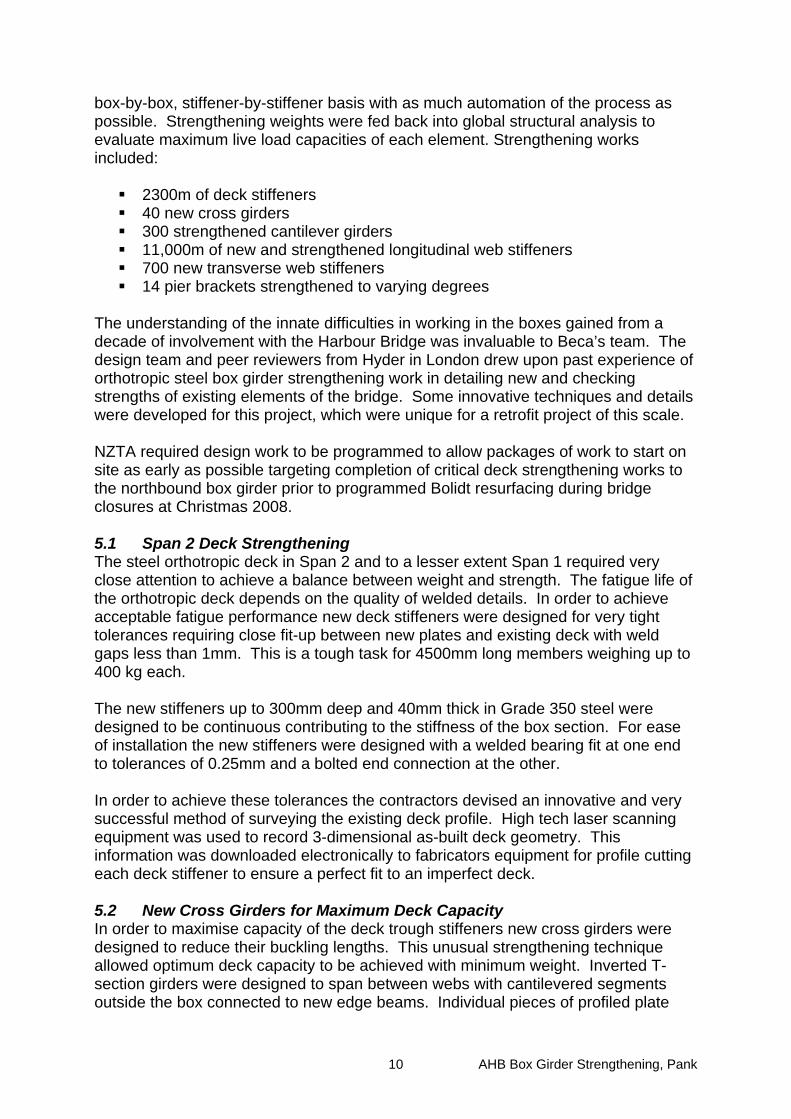
box-by-box, stiffener-by-stiffener basis with as much automation of the process as possible. Strengthening weights were fed back into global structural analysis to evaluate maximum live load capacities of each element. Strengthening works included:
2300m of deck stiffeners 40 new cross girders 300 strengthened cantilever girders 11,000m of new and strengthened longitudinal web stiffeners 700 new transverse web stiffeners 14 pier brackets strengthened to varying degrees
The understanding of the innate difficulties in working in the boxes gained from a decade of involvement with the Harbour Bridge was invaluable to Beca’s team. The design team and peer reviewers from Hyder in London drew upon past experience of orthotropic steel box girder strengthening work in detailing new and checking strengths of existing elements of the bridge. Some innovative techniques and details were developed for this project, which were unique for a retrofit project of this scale. NZTA required design work to be programmed to allow packages of work to start on site as early as possible targeting completion of critical deck strengthening works to the northbound box girder prior to programmed Bolidt resurfacing during bridge closures at Christmas 2008. 5.1 Span 2 Deck Strengthening The steel orthotropic deck in Span 2 and to a lesser extent Span 1 required very close attention to achieve a balance between weight and strength. The fatigue life of the orthotropic deck depends on the quality of welded details. In order to achieve acceptable fatigue performance new deck stiffeners were designed for very tight tolerances requiring close fit-up between new plates and existing deck with weld gaps less than 1mm. This is a tough task for 4500mm long members weighing up to 400 kg each. The new stiffeners up to 300mm deep and 40mm thick in Grade 350 steel were designed to be continuous contributing to the stiffness of the box section. For ease of installation the new stiffeners were designed with a welded bearing fit at one end to tolerances of 0.25mm and a bolted end connection at the other. In order to achieve these tolerances the contractors devised an innovative and very successful method of surveying the existing deck profile. High tech laser scanning equipment was used to record 3-dimensional as-built deck geometry. This information was downloaded electronically to fabricators equipment for profile cutting each deck stiffener to ensure a perfect fit to an imperfect deck. 5.2 New Cross Girders for Maximum Deck Capacity In order to maximise capacity of the deck trough stiffeners new cross girders were designed to reduce their buckling lengths. This unusual strengthening technique allowed optimum deck capacity to be achieved with minimum weight. Inverted T-section girders were designed to span between webs with cantilevered segments outside the box connected to new edge beams. Individual pieces of profiled plate
AHB Box Girder Strengthening, Pank 11
had to be inserted between deck troughs and new flat plate stiffeners. Laser scanning techniques again enabled extremely accurate survey information to be passed to the cutting equipment while a well-documented tracking system ensured that each piece of the jigsaw was fitted into the correct slot on the bridge. All the Span 2 deck strengthening was designed to be installed with no traffic loading and in a sequence to minimise locked in stresses from construction loading. Weld sequences were developed through discussions with the Heavy Engineering Research Association (HERA) to minimise residual stresses and distortion from weld shrinkage.
Figure 7 - Elevation of new cross girder showing connection to new and existing deck stiffeners 5.3 Web Panel Buckling Extensive areas of the box girder in compression zones required strengthening to increase web panel buckling capacity and to stiffen existing longitudinal web stiffeners. Weight and installation costs were governing factors in finding the optimum design solution for web strengthening. New intermediate transverse web stiffeners installed between existing greatly improved longitudinal web stiffener buckling capacity and reduced the number of existing stiffeners to be strengthened. Top web panels at midspan and bottom panels at piers were divided in half with new longitudinal stiffeners to reduce buckling wavelengths. Many of the existing longitudinal angle stiffeners did not satisfy standards and to limit weight strengthening measures were rationalised into a number of new stiffener types. For large angles not locally available Beca and project partners researched international markets and sourced Japanese angles up to 300mm deep. In order to minimise the lead-in times for steel delivery these angles and large quantities of heavy plate were purchased directly by NZTA and shipped to Auckland in advance of construction contracts. 5.4 Re-retrofit of Pier Brackets The effects of increased traffic loads and refinements to wind loading arising from wind tunnel testing meant that the pier brackets supporting the box girder bridges had to be very carefully strengthened again after two previous retrofits. Load paths were followed in detail from trestle bearings, onto bearing stiffeners and diaphragm beams inside the brackets, through welds to side plates, along stiffened webs and flanges to the original concrete piers. Strengthening measures included:
AHB Box Girder Strengthening, Pank 12
New and replacement diaphragm bearing stiffeners Diaphragm beam plating Side plate plating and stiffening Bottom flange stiffening Over-welding to increase weld strength New stress bars connected to Pier 4 brackets
The outcome of this detailed assessment and design is a set of complex drawings with specified construction sequences that amount complex localised surgery to be delicately carried out in the tight confines of the brackets where access is restricted. To check the findings of the pier bracket strengthening design FE analysis was carried out by Beca. It was very reassuring when Hyder created and analysed new bracket FE models independently to find that they came up with remarkably similar results from the analysis of the complex structures.
Figure 8 - Pier 3 bracket FE model showing stress concentrations around internal diaphragms
6.0 SITE CONTRAINTS AND ENABLING WORKS The detail design of the proposed works was a long and thorough process requiring minute attention to detail and management of masses of information. The work demands offsite fabrication, delivery, lifting, fitting and connecting thousands of small pieces of steel often individually tailored to specific locations in the bridge. It is an extremely labour intensive job with tough health and safety requirements, where skilled man-power on site is critical to success and raw material input represents only a fraction of the costs of the work. Beca is currently working with contractors both managing the project and providing design assistance throughout the complex 3 year strengthening works. Several hundred tonnes of steel plate and angles are to be installed in pieces less than 5m long into the confined space of a working structure 1100m long and more than 40m above the harbour. This is an enormous logistical exercise. It was identified early in the design process that existing access, power, ventilation, lighting and site facilities needed upgrading before strengthening could begin.
AHB Box Girder Strengthening, Pank 13
A highly successful innovation for this project was the installation of a materials handling system let as an advanced works package. The design of a train running on tracks mounted on an existing walkway inside the box girder was developed by Beca and Ikon Engineering with assistance from TBS, and implemented by Brian Perry Civil. The train (shown in figure 9) is capable of carrying 5m lengths of heavy steel through existing diaphragm openings 600mm wide with fully mechanised lifting equipment to load custom built carriages. This innovative solution has been invaluable throughout the project and has saved many man-hours through the ease of delivering steel to work fronts when needed.
The main contractor Total Bridge Services (TBS) has made access improvements to the bridge including:
New rail mounted welding platforms for external strengthening New deep box gantries for external web plating (see figure 10 above) New lower chord walkways for access to piers
Several thousand square meters of paint has been removed including lead paint with all the inherent health and safety issues of working with lead. At the time of writing deck strengthening work has been completed on the north-bound extension bridge and work is progressing on the webs and pier brackets. After completion of critical works on the west box work will be carried out under closures on the eastern south-bound bridge and the strengthening is programmed for completion in 2010.
Figure 10 - Photo showing deep box gantry used to install external web plating
AHB Box Girder Strengthening, Pank 14
Acknowledgements: The major inputs of the design team members including Mike Beamish, Melanie Regino and Matt Sturge have been a key to the success of this project. The enthusiastic assistance and support of the New Zealand Transport Agency, in particular Robert Strong, Bryson Hosie and Rudolph Kotze are gratefully acknowledged.