Page 2 Effective: March 2014 100-1600A ATC-300+/800 Contactor Open/ClosedTransition Fixed/Dual Drawout Bypass Isolation Transfer Switch
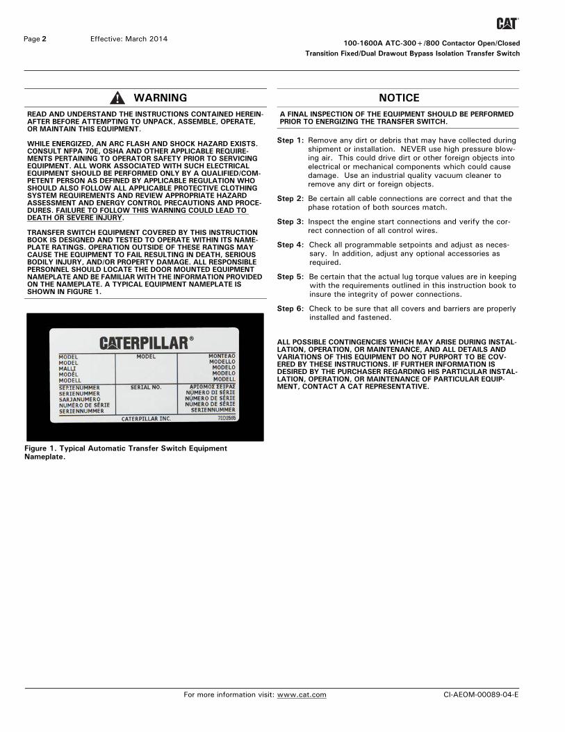
Figure 1. Typical Automatic Transfer Switch Equipment Nameplate.
Step 1: Remove any dirt or debris that may have collected during shipment or installation. NEVER use high pressure blow-ing air. This could drive dirt or other foreign objects into electrical or mechanical components which could cause damage. Use an industrial quality vacuum cleaner to remove any dirt or foreign objects.
Step 2: Be certain all cable connections are correct and that the phase rotation of both sources match.
Step 3: Inspect the engine start connections and verify the cor-rect connection of all control wires.
Step 4: Check all programmable setpoints and adjust as neces-sary. In addition, adjust any optional accessories as required.
Step 5: Be certain that the actual lug torque values are in keeping with the requirements outlined in this instruction book to insure the integrity of power connections.
Step 6: Check to be sure that all covers and barriers are properly installed and fastened.
ALL POSSIBLE CONTINGENCIES WHICH MAY ARISE DURING INSTAL-LATION, OPERATION, OR MAINTENANCE, AND ALL DETAILS AND VARIATIONS OF THIS EQUIPMENT DO NOT PURPORT TO BE COV-ERED BY THESE INSTRUCTIONS. IF FURTHER INFORMATION IS DESIRED BY THE PURCHASER REGARDING HIS PARTICULAR INSTAL-LATION, OPERATION, OR MAINTENANCE OF PARTICULAR EQUIP-MENT, CONTACT A CAT REPRESENTATIVE.
WARNINGREAD AND UNDERSTAND THE INSTRUCTIONS CONTAINED HEREIN-AFTER BEFORE ATTEMPTING TO UNPACK, ASSEMBLE, OPERATE, OR MAINTAIN THIS EQUIPMENT.
WHILE ENERGIZED, AN ARC FLASH AND SHOCK HAZARD EXISTS. CONSULT NFPA 70E, OSHA AND OTHER APPLICABLE REQUIRE-MENTS PERTAINING TO OPERATOR SAFETY PRIOR TO SERVICING EQUIPMENT. ALL WORK ASSOCIATED WITH SUCH ELECTRICAL EQUIPMENT SHOULD BE PERFORMED ONLY BY A QUALIFIED/COM-PETENT PERSON AS DEFINED BY APPLICABLE REGULATION WHO SHOULD ALSO FOLLOW ALL APPLICABLE PROTECTIVE CLOTHING SYSTEM REQUIREMENTS AND REVIEW APPROPRIATE HAZARD ASSESSMENT AND ENERGY CONTROL PRECAUTIONS AND PROCE-DURES. FAILURE TO FOLLOW THIS WARNING COULD LEAD TO DEATH OR SEVERE INJURY.
TRANSFER SWITCH EQUIPMENT COVERED BY THIS INSTRUCTION BOOK IS DESIGNED AND TESTED TO OPERATE WITHIN ITS NAME-PLATE RATINGS. OPERATION OUTSIDE OF THESE RATINGS MAY CAUSE THE EQUIPMENT TO FAIL RESULTING IN DEATH, SERIOUS BODILY INJURY, AND/OR PROPERTY DAMAGE. ALL RESPONSIBLE PERSONNEL SHOULD LOCATE THE DOOR MOUNTED EQUIPMENT NAMEPLATE AND BE FAMILIAR WITH THE INFORMATION PROVIDED ON THE NAMEPLATE. A TYPICAL EQUIPMENT NAMEPLATE IS SHOWN IN FIGURE 1.
NOTICEA FINAL INSPECTION OF THE EQUIPMENT SHOULD BE PERFORMED PRIOR TO ENERGIZING THE TRANSFER SWITCH.
For more information visit: www.cat.com CI-AEOM-00089-04-E
Effective: March 2014 Page 3100-1600A ATC-300+/800 Contactor Open/ClosedTransition Fixed/Dual Drawout Bypass Isolation Transfer Switch
Section 1: Introduction1.1 Preliminary Comments and Safety PrecautionsThis technical document is intended to cover most aspects associ-ated with the installation, application, operation, and maintenance of ATC-300+/800 controlled contactor based transfer switch equipment with ratings from 100 through 1600 amperes (A). It is provided as a guide for authorized and qualified personnel only. Please refer to the specific WARNING and CAUTION in Section 1.1.2 before proceeding. If further information is required by the purchaser regarding a particular installation, application, or mainte-nance activity, contact a Cat dealer. For information associated with the control, refer to the separate instruction book pertaining to the logic package installed in the switch.
1.1.1 Warranty and Liability InformationNo warranties, expressed or implied, including warranties of fit-ness for a particular purpose of merchant-ability, or warranties arising from course of dealing or usage of trade, are made regard-ing the information, recommendations and descriptions contained herein. In no event will Caterpillar be responsible to the purchaser or user in contract, in tort (including negligence), strict liability or otherwise for any special, indirect, incidental or consequential damage or loss whatsoever, including but not limited to damage or loss of use of equipment, plant or power system, cost of capital, loss of power, additional expenses in the use of existing power facilities, or claims against the purchaser or user by its customers resulting from the use of the information and descriptions con-tained herein.
1.1.2 Safety PrecautionsAll safety codes, safety standards, and/or regulations must be strictly observed in the installation, operation, and maintenance of this device.
.
1.2 General InformationTransfer switches are used to protect critical electrical loads against loss of power. The Source 1 power source of the load is backed-up by a Source 2 power source. A transfer switch is con-nected to both the Source 1 and Source 2 power sources and sup-plies the load with power from one of these two sources. In the event that power is lost from the Source 1 power source, the transfer switch transfers the load to the Source 2 power source. This transfer can be automatic or manual, depending upon the type of transfer switch equipment being used. Once Source 1 power is restored, the load is automatically or manually trans-ferred back to the Source 1 power source, again depending upon the type of transfer equipment being used (Figure 2).In addition, the closed transition feature may be applied where it is desirable to avoid any momentary power interruptions. Although the closed transition switch is not a substitute for an uninterupt-able power source (UPS), it does eliminate power interruptions to loads except to those caused by power sources or equipment external to the transfer switch. If both sources are acceptable as determined by the ATC-800 controller. A make-before-break transfer is performed during a transfer test or retransfer operation using the bypass contactor momentarily.
Figure 2. Typical Load Transfer Switch (Switching Device Type) Schematic. One Three Position, Closed on Source 1, Contactor Shown.
WARNINGTHE WARNINGS AND CAUTIONS INCLUDED AS PART OF THE PRO-CEDURAL STEPS IN THIS DOCUMENT ARE FOR PERSONNEL SAFETY AND PROTECTION OF EQUIPMENT FROM DAMAGE. AN EXAMPLE OF A TYPICAL WARNING LABEL HEADING IS SHOWN ABOVE TO FAMILIARIZE PERSONNEL WITH THE STYLE OF PRESENTATION. THIS WILL HELP TO INSURE THAT PERSONNEL ARE ALERT TO WARNINGS, WHICH APPEAR THROUGHOUT THE DOCUMENT. IN ADDITION, CAUTIONS ARE ALL UPPER CASE AND BOLDFACE.
CAUTIONDO NOT ATTEMPT TO SERVICE OR PERFORM MAINTENANCE ON EQUIPMENT WHILE IT IS ENERGIZED. FAILURE TO FOLLOW THIS WARNING COULD LEAD TO DEATH OR SEVERE INJURY. ALWAYS VERIFY THAT NO VOLTAGE IS PRESENT ON EQUIPMENT PRIOR TO SERVICING. WHILE ENERGIZED, AN ARC FLASH AND SHOCK HAZ-ARD EXISTS. CONSULT NFPA 70E AND OSHA GUIDELINES FOR OPERATOR SAFETY PRIOR TO OPERATING, INSPECTING OR SERVIC-ING EQUIPMENT.
WARNINGTHE CLOSED TRANSITION PRODUCT CONTAINS A SPECIAL CON-TACT ARRANGEMENT (OVERLAPPING CONTACTS). MISUSE CAN RESULT IN DEATH, SEVERE PERSONAL INJURY, AND/OR PROPERTY DAMAGE.
CI-AEOM-00089-04-E For more information visit: www.cat.com
Page 4 Effective: March 2014 100-1600A ATC-300+/800 Contactor Open/ClosedTransition Fixed/Dual Drawout Bypass Isolation Transfer Switch
1.2.1 Transfer Switch Types
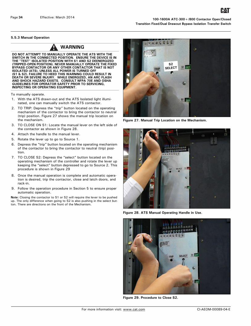
Open/closed transition bypass isolation type automatic transfer switches consist of four basic elements.
1. Main contacts to connect and disconnect the load to and from the source of power.
2. Intelligence/supervisory circuits to constantly monitor the con-dition of the power sources and thus provide the intelligence necessary for the switch and related circuit operation.
3. A transfer mechanism to effect the transfer of the main con-tacts from source to source.
4. Voltage selection, bypass selection, and transformer panel.
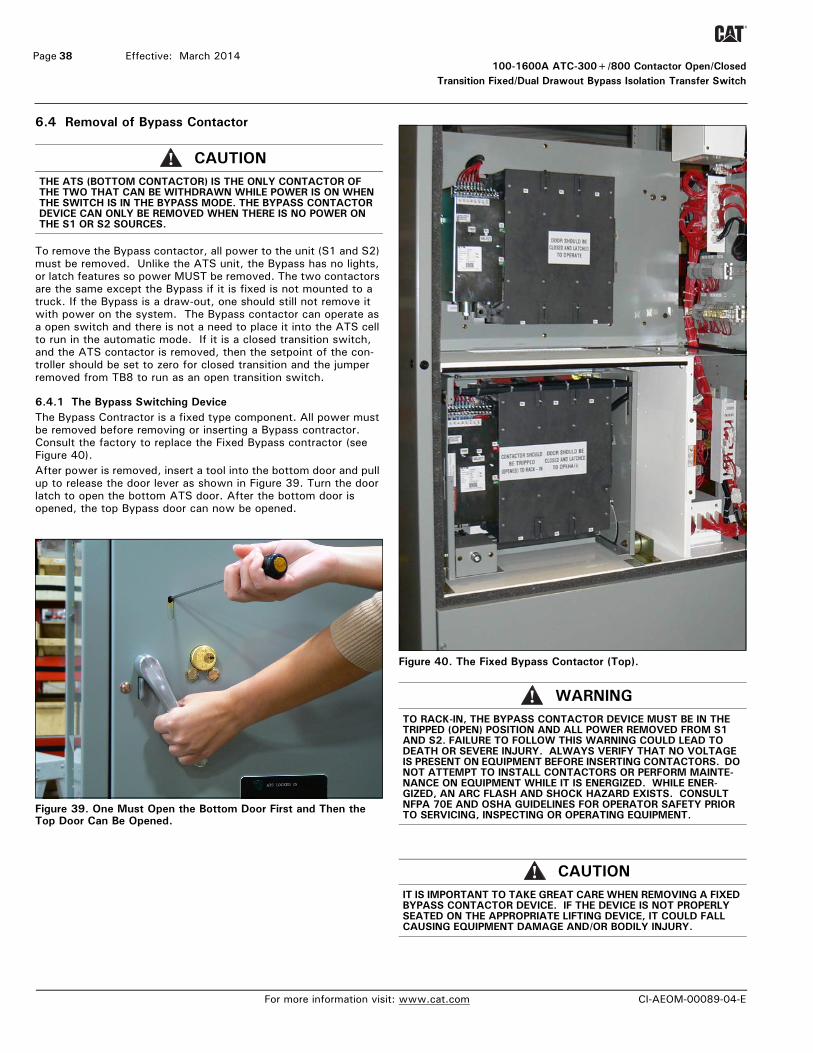
The Fixed Bypass Isolation Switch shown in Figure 3 is designed for applications where maintenance, inspection, and testing must be performed while maintaining continuous power to the load. This is typically required in critical life support systems and standby power situations calling for safe system maintenance with no power disruptions. Such a design allows for the quick removal of the ATS switching devices for inspection, mainte-nance, or replacement.
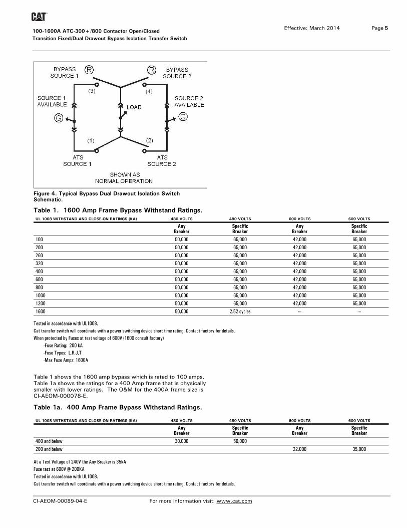
1.2.2 Design ConfigurationThe Cat transfer switch is a rugged, compact design utilizing power contactors to transfer essential loads from one power source to another. Open transition switching devices are inter-locked to prevent both switching devices from being closed at the same time. The switching devices are in a compact vertical arrangement. The logic can be easily disconnected from the switching device with-out disturbing critical connections. The enclosure is free standing, and is seismic approved. The terminals are mounted in the rear of the switch for front access, permitting rear, top, bottom, or side cable entrance. The terminals also can be mounted on the top or bottom or any assortment of that.The switching devices have a high withstand rating (Table 1). Fig-ure 4 shows the schematic of the Bypass Isolation Switch. There are two contactors that enable the transfer as a bypass in an open or closed transition. The unit can also be operated as a redundant switch with the controller being full activated with the primary (ATS) or redundant (Bypass) switch.
Figure 3.Typical Fixed Bypass Isolation Switch.
For more information visit: www.cat.com CI-AEOM-00089-04-E
Effective: March 2014 Page 5100-1600A ATC-300+/800 Contactor Open/ClosedTransition Fixed/Dual Drawout Bypass Isolation Transfer Switch
Tested in accordance with UL1008.Cat transfer switch will coordinate with a power switching device short time rating. Contact factory for details.When protected by Fuses at test voltage of 600V (1600 consult factory)
Table 1 shows the 1600 amp bypass which is rated to 100 amps. Table 1a shows the ratings for a 400 Amp frame that is physically smaller with lower ratings. The O&M for the 400A frame size is CI-AEOM-000078-E.
Table 1a. 400 Amp Frame Bypass Withstand Ratings.
At a Test Voltage of 240V the Any Breaker is 35kAFuse test at 600V @ 200KATested in accordance with UL1008.Cat transfer switch will coordinate with a power switching device short time rating. Contact factory for details.
UL 1008 WITHSTAND AND CLOSE-ON RATINGS (KA) 480 VOLTS 480 VOLTS 600 VOLTS 600 VOLTS
AnyBreaker
SpecificBreaker
AnyBreaker
SpecificBreaker
100 50,000 65,000 42,000 65,000
200 50,000 65,000 42,000 65,000
260 50,000 65,000 42,000 65,000
320 50,000 65,000 42,000 65,000
400 50,000 65,000 42,000 65,000
600 50,000 65,000 42,000 65,000
800 50,000 65,000 42,000 65,000
1000 50,000 65,000 42,000 65,000
1200 50,000 65,000 42,000 65,000
1600 50,000 2.52 cycles --- ---
UL 1008 WITHSTAND AND CLOSE-ON RATINGS (KA) 480 VOLTS 480 VOLTS 600 VOLTS 600 VOLTS
AnyBreaker
SpecificBreaker
AnyBreaker
SpecificBreaker
400 and below 30,000 50,000
200 and below 22,000 35,000
CI-AEOM-00089-04-E For more information visit: www.cat.com
Page 6 Effective: March 2014 100-1600A ATC-300+/800 Contactor Open/ClosedTransition Fixed/Dual Drawout Bypass Isolation Transfer Switch
1.3 Draw-out Switching DeviceAll switching devices are 100% rated, Underwriters Laboratories (UL) 1008 listed, and are built and tested in an ISO 9002 certified facility to applicable NEMA, ANSI, IEEE, and UL standards. The main difference between the ATS and the Bypass versions of the switching devices (contactors) used in the bypass isolation transfer switch is that the Bypass contactor is fixed with no truck enabling it to be drawn out. With the Dual Drawout version, both contactors can be removed as they both have trucks (BP is only removed with power off). Figure 5 shows the two contactors in the switch. The bottom is the ATS contactor and the top is the bypass contactor. The ATS contactor will do nearly all of the cur-rent transfer for the loads during the life of the switch. The ATS switching device is mounted with safety interlocks, in a "truck" mechanism, allowing the switching device to be “drawn-out” for service, maintenance, and/or replacement. The Bypass device is a fixed type contactor.
Figure 5. Switching Devices Installed in the Transfer Switch (Fixed Type Shown).
1.3.1 Draw-out Switching DevicesThe ATS draw-out switching device is a design having three posi-tions with the compartment door closed (Locked In, Isolated, and Removed). Figure 6 shows the contactor fully disconnected from the transfer switch. In this case, the primary and secondary con-nectors are disconnected. It is ready for removal. The ATS draw-out switching device is equipped with both primary and secondary disconnects to provide for the draw-out functioning. The primary contacts (Figure 7) are the S1, S2, and load contacts. The sec-ondary contacts are the control and feedback contacts. The sec-ondary connector is on the side of the truck (top left of truck for the 1600 amp) and is somewhat floating for easy racking-in. The operating mechanism is electrically operated and also has a mechanical operation if required in an emergency. When with-drawn, the ATS switching device can be inspected, tested, and minor maintenance performed. The inside of the compartment can also be inspected with the ATS switching device withdrawn. Caution must be taken as there is voltage on the run-backs (cop-per) in the back of the cell once the contactor is removed.
Figure 6. Draw-out Switching Device Fully Extended from the Transfer Switch's Runbacks.
BYPASS
ATS
WARNINGDO NOT ATTEMPT TO PERFORM MAINTENANCE OR SERVICE EQUIPMENT WHILE IT IS ENERGIZED. FAILURE TO FOLLOW THIS WARNING COULD LEAD TO DEATH OR SEVERE INJURY. ALWAYS VERIFY THAT NO VOLTAGE IS PRESENT ON EQUIPMENT PRIOR TO SERVICING. WHILE ENERGIZED, AN ARC FLASH AND SHOCK HAZ-ARD EXISTS. CONSULT NFPA 70E AND OSHA GUIDELINES FOR OPERATOR SAFETY PRIOR TO SERVICING OR OPERATING EQUIP-MENT.
For more information visit: www.cat.com CI-AEOM-00089-04-E
Effective: March 2014 Page 7100-1600A ATC-300+/800 Contactor Open/ClosedTransition Fixed/Dual Drawout Bypass Isolation Transfer Switch
Figure 7. Primary Connections on the ATS Switching Device, Four Pole 1200 Amp Shown. The Secondary Connector Is on the Right Side for the 1200 Amp and on the Top Left for the 1600 Amp.
1.4 Transfer Switch Catalog Number Identification Transfer switch equipment catalog numbers provide a significant amount of relevant information that pertains to a particular piece of equipment. The catalog number identification table (Table 2) provides the required interpretation information. An example for an open transition switch is offered to initially simplify the pro-cess.Example: Catalog Number (circled numbers correspond to position headings in Table 2).
The catalog number BIC8C3X31200XSU describes a fixed bypass isolation transfer switch with the switching devices mounted ver-tically in the enclosure. The intelligence, represented by the ATC-800 is a microprocessor-based logic package. The contactor is used as the switching device and is a 3-pole for each source. The continuous current rating of this equipment is 800A and is appli-cable at 480 Vac, 60 Hz. The transfer switch equipment is enclosed in a NEMA 1 enclosure and is listed for Underwriters Laboratories (UL) and Canadian Standards Association (CSA) applications.
Table 2. Transfer Switch Catalog Number Explanation.
1.5 Environmental Conditions
1.5.1 Operational Conditions
Normally, an ATS is applied indoors in an electrical equipment room. In the appropriate enclosure, it can be used for outdoor applications where the equipment is subject to falling rain, freez-ing temperatures, and no greater than 90% humidity (non-con-densing). The ambient temperature range for operation is between -20 and 70°C (-4 to 158°F). A heater may be required.
Note: The 1600 amp switch only comes as a Dual Draw-out type.
CI-AEOM-00089-04-E For more information visit: www.cat.com
Page 8 Effective: March 2014 100-1600A ATC-300+/800 Contactor Open/ClosedTransition Fixed/Dual Drawout Bypass Isolation Transfer Switch
1.6 Glossary
With respect to their use within this document and as they relate to transfer switch and controller operation, the following terminol-ogy is defined.
AvailableA source is defined as “available” when it is within its undervolt-age/overvoltage/ underfrequency/overfrequency (if applicable) set-point ranges for the nominal voltage and frequency setting.
BypassTo transfer to another contactor, same source, with no power interruption.
ConnectedConnected is defined as when the input is shorted by an external contact or connection.
Failed or FailsA source is defined as “failed” when it is outside of the applicable voltage and frequency setpoint ranges for the nominal voltage and frequency setting for a time exceeding 0.5 seconds after the time delay emergency fail (TDEF) time delays expires.
FailsafeFailsafe is a feature that prevents disconnection from the only available power source and also forces a transfer or re-transfer operation to the only available power source.
Re-TransferRe-transfer is defined as a change of the load connection from the Source 2 to the Source 1.
Source 1Source 1 is the primary source (normal source, normal power source, or normal).
Source 2Source 2 is the secondary source (emergency source, emergency power source, emergency, standby, or backup source).
Source 1: Failed or FailsSource 1 is defined as “failed” when it is outside of its undervolt-age/overvoltage/ underfrequency/overfrequency (if applicable) set-point ranges for the nominal voltage and frequency setting.
Source 2: Failed or FailsSource 2 is defined as “failed” when it is outside of its undervolt-age/overvoltage/ underfrequency/overfrequency (if applicable) set-point ranges for the nominal voltage and frequency setting for a time exceeding 0.5 seconds after the Time Delay Emergency Fail (TDEF) time delay expires.
TransferTransfer is defined as a change of the load connection from the Source 1 to the Source 2 power source.
TripDevice is not connected to Source 1/ or Source 2.Device is open.
UnconnectedUnconnected is defined as when the input is not shorted by an external contact or connection.
Section 2: Receiving, Handling, and Storage2.1 ReceivingEvery effort is made to ensure that the transfer switch equipment arrives at its destination undamaged and ready for installation. Crating and packing is designed to protect internal components as well as the enclosure. Transfer switch enclosures are skid mounted and suited for fork lift movement. Care should be exer-cised, however, to protect the equipment from impact at all times. Do not remove the protective packaging until the equipment is at the installation location and ready for installation.When the transfer switch equipment reaches its destination, the customer should inspect the shipping container for any obvious signs of rough handling and/or external damage incurred during transportation. Record any external and internal damage observed for reporting to the transportation carrier and Caterpillar, once a thorough inspection is completed. All claims should be as specific as possible and include the serial number.A shipping label which includes a variety of equipment and cus-tomer information is affixed to the top of the shipping container. Make certain that this information matches other shipping paper information.Each transfer switch enclosure is bolted to a rigid wooden pallet. The pallet is open at two ends for movement by a fork lift. The shipment is secured and further protected with shrink wrap. Do not discard the packing material until the equipment is ready for installation.A plastic bag of documents will be found within the enclosure, usually attached to the inside of the door. Important documents, such as test reports, wiring diagrams, and appropriate instruction leaflets, are enclosed within the bag and should be filed in a safe place. There are also keys for the unit.
2.2 HandlingAs previously mentioned, the transfer switch equipment is pack-aged for fork lift movement. Protect the equipment from impact at all times and DO NOT double stack. Once the equipment is at the installation location and ready for installation, the packaging material can be removed. Once the enclosure is unbolted from the wooden pallet, it can be installed using the lifting provision located on the top of the structure. Be careful not to damage the top or bottom enclosure mounting flanges. Refer to Section 4 of this manual for specific installation instructions.
2.3 StorageAlthough well packaged, this equipment is not suitable for storage outdoors. The equipment warranty will not be applicable if there is evidence of outdoor storage. If the equipment is to be stored indoors for any period of time, it should be stored with its protec-tive packaging material in place. Protect the equipment at all times from excessive moisture, construction dirt, corrosive condi-tions, and other contaminants.It is strongly suggested that the package-protected equipment be stored in a climate controlled environment of -20° to 85°C (-4° to 185°F) with a relative humidity of 80% or less. DO NOT, under any circumstances, stack other equipment on top of a trans-fer switch equipment enclosure, whether packaged or not.
For more information visit: www.cat.com CI-AEOM-00089-04-E
Effective: March 2014 Page 9100-1600A ATC-300+/800 Contactor Open/ClosedTransition Fixed/Dual Drawout Bypass Isolation Transfer Switch
Section 3: Equipment Description3.1 General
The ATS consists of:
1. The power panel; consisting of the contactors switching devices with the truck for the ATS in a fixed switch.
2. The voltage selection and transformer pack;
3. The bypass logic panel;
4. The relay panel;
5. The door including the ATC controller, control switches, Kirk-Key, Optional Meter
6. The bus.
7. Terminal Blocks
The panels are interconnected via connector plugs and mounted in an enclosure (Figure 8a). The top and bottom wiring are also shown in Figure 8b and 8c.
Figure 8a. Basic Panels of the Bypass Isolation Switch (600-1200A Fixed).
Contactors Relay Panel
Individual Door Components
ATC-Controller
Switches
Doors with
Bypass Logic
TransformerPack
Bus
Components
User
BlocksTerminal
(BottomConnectShown)
Load
S2 S1
CI-AEOM-00089-04-E For more information visit: www.cat.com
Page 10 Effective: March 2014 100-1600A ATC-300+/800 Contactor Open/ClosedTransition Fixed/Dual Drawout Bypass Isolation Transfer Switch
Figure 8.
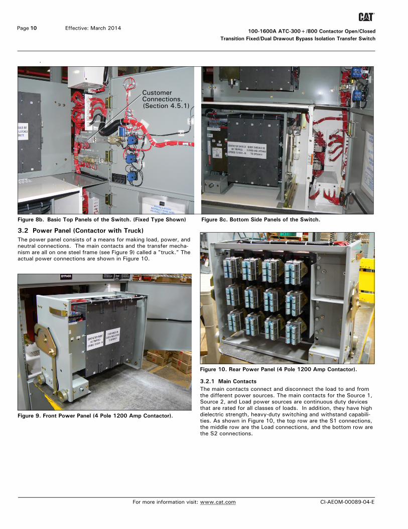
Figure 8b. Basic Top Panels of the Switch. (Fixed Type Shown) Figure 8c. Bottom Side Panels of the Switch.
3.2 Power Panel (Contactor with Truck)The power panel consists of a means for making load, power, and neutral connections. The main contacts and the transfer mecha-nism are all on one steel frame (see Figure 9) called a "truck." The actual power connections are shown in Figure 10.
Figure 9. Front Power Panel (4 Pole 1200 Amp Contactor).
Figure 10. Rear Power Panel (4 Pole 1200 Amp Contactor).
3.2.1 Main ContactsThe main contacts connect and disconnect the load to and from the different power sources. The main contacts for the Source 1, Source 2, and Load power sources are continuous duty devices that are rated for all classes of loads. In addition, they have high dielectric strength, heavy-duty switching and withstand capabili-ties. As shown in Figure 10, the top row are the S1 connections, the middle row are the Load connections, and the bottom row are the S2 connections.
Customer
(Section 4.5.1)Connections.
For more information visit: www.cat.com CI-AEOM-00089-04-E
Effective: March 2014 Page 11100-1600A ATC-300+/800 Contactor Open/ClosedTransition Fixed/Dual Drawout Bypass Isolation Transfer Switch
3.2.2 Switch Interlocks (Open Transition Only)Cat transfer switches are electrically interlocked to prevent the two sets of main contacts from being closed simultaneously except in closed transition mode or transferring to the Bypass function (same source).
3.2.3 Draw-out Interlocks The ATS switching device is electronically interlocked to the draw-out mechanism to ensure that the switching device is always in the neutral position when connecting or disconnecting it from the line and load stabs.The switching device will close on an available source only with the doors closed and latched. During the test mode, in the iso-lated position, the ATS contactor can be electrically or mechani-cally operated for testing.
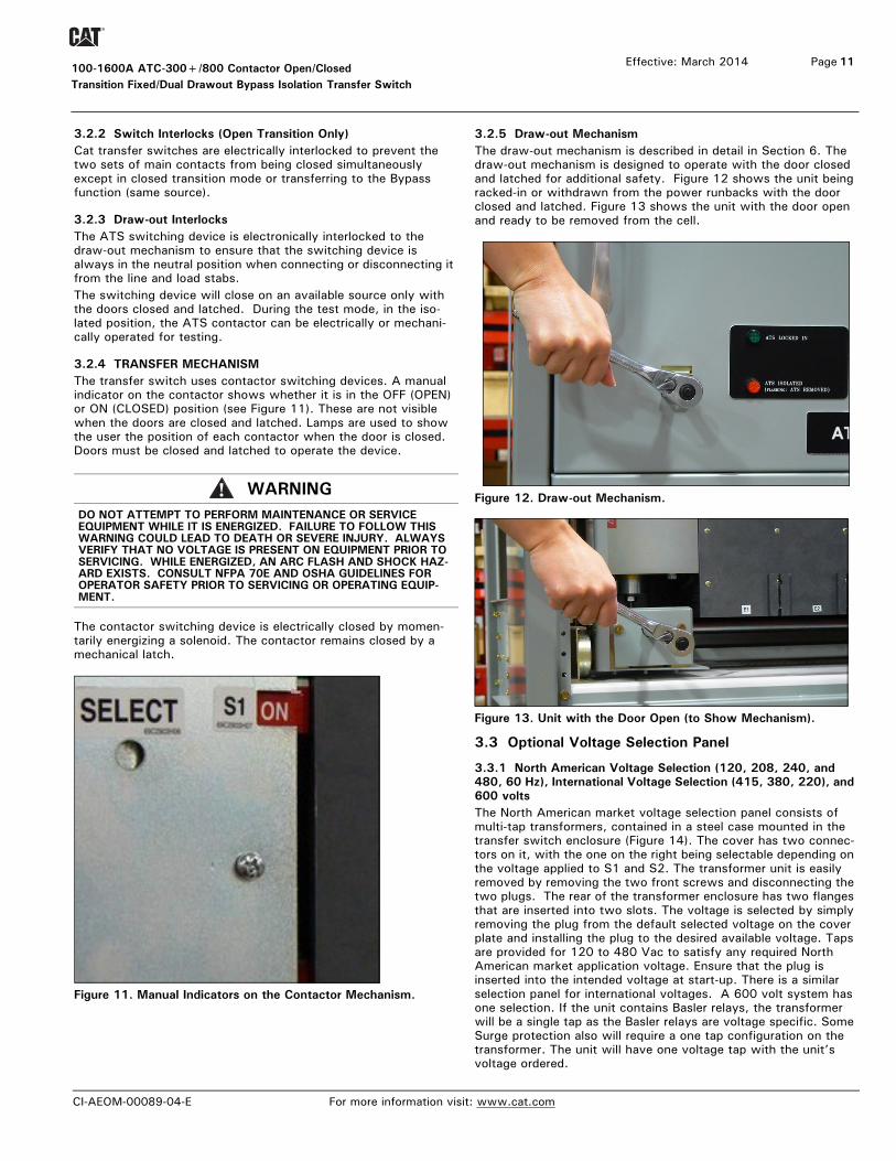
3.2.4 TRANSFER MECHANISMThe transfer switch uses contactor switching devices. A manual indicator on the contactor shows whether it is in the OFF (OPEN) or ON (CLOSED) position (see Figure 11). These are not visible when the doors are closed and latched. Lamps are used to show the user the position of each contactor when the door is closed. Doors must be closed and latched to operate the device.
The contactor switching device is electrically closed by momen-tarily energizing a solenoid. The contactor remains closed by a mechanical latch.
Figure 11. Manual Indicators on the Contactor Mechanism.
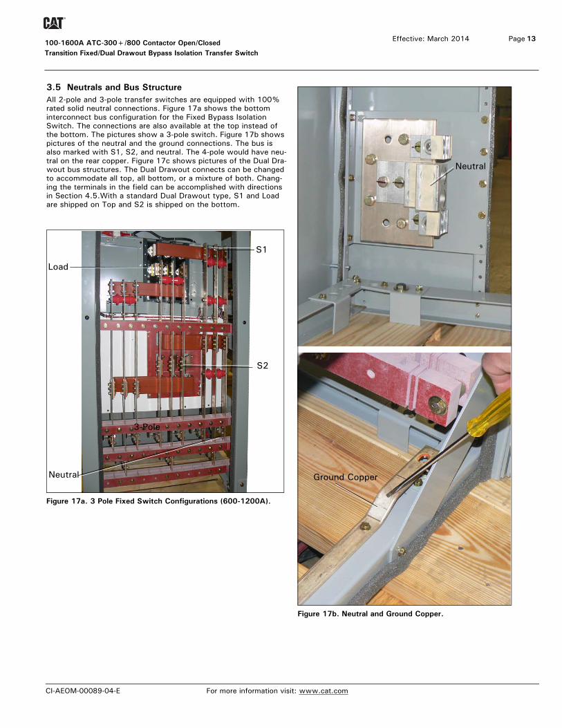
3.2.5 Draw-out MechanismThe draw-out mechanism is described in detail in Section 6. The draw-out mechanism is designed to operate with the door closed and latched for additional safety. Figure 12 shows the unit being racked-in or withdrawn from the power runbacks with the door closed and latched. Figure 13 shows the unit with the door open and ready to be removed from the cell.
Figure 12. Draw-out Mechanism.
Figure 13. Unit with the Door Open (to Show Mechanism).
3.3 Optional Voltage Selection Panel
3.3.1 North American Voltage Selection (120, 208, 240, and 480, 60 Hz), International Voltage Selection (415, 380, 220), and 600 voltsThe North American market voltage selection panel consists of multi-tap transformers, contained in a steel case mounted in the transfer switch enclosure (Figure 14). The cover has two connec-tors on it, with the one on the right being selectable depending on the voltage applied to S1 and S2. The transformer unit is easily removed by removing the two front screws and disconnecting the two plugs. The rear of the transformer enclosure has two flanges that are inserted into two slots. The voltage is selected by simply removing the plug from the default selected voltage on the cover plate and installing the plug to the desired available voltage. Taps are provided for 120 to 480 Vac to satisfy any required North American market application voltage. Ensure that the plug is inserted into the intended voltage at start-up. There is a similar selection panel for international voltages. A 600 volt system has one selection. If the unit contains Basler relays, the transformer will be a single tap as the Basler relays are voltage specific. Some Surge protection also will require a one tap configuration on the transformer. The unit will have one voltage tap with the unit’s voltage ordered.
WARNINGDO NOT ATTEMPT TO PERFORM MAINTENANCE OR SERVICE EQUIPMENT WHILE IT IS ENERGIZED. FAILURE TO FOLLOW THIS WARNING COULD LEAD TO DEATH OR SEVERE INJURY. ALWAYS VERIFY THAT NO VOLTAGE IS PRESENT ON EQUIPMENT PRIOR TO SERVICING. WHILE ENERGIZED, AN ARC FLASH AND SHOCK HAZ-ARD EXISTS. CONSULT NFPA 70E AND OSHA GUIDELINES FOR OPERATOR SAFETY PRIOR TO SERVICING OR OPERATING EQUIP-MENT.
CI-AEOM-00089-04-E For more information visit: www.cat.com
Page 12 Effective: March 2014 100-1600A ATC-300+/800 Contactor Open/ClosedTransition Fixed/Dual Drawout Bypass Isolation Transfer Switch
Figure 14. Optional Transformer Selection Terminals (Shown Connected to the 120 Vac Tap) (Dual Drawout Shown).
3.4 ATC ControllersThe Controller panel provides the intelligence and supervisory cir-cuits which constantly monitor the condition of both the Source 1 and Source 2 power sources, thus providing the required intelli-gence for transfer operations (see Figures 15 and 16). Detailed information for controller operation is presented in separate docu-ments:
Figure 15. ATC-300+.
Figure 16. ATC-800.
DANGERWHEN CHANGING THE VOLTAGE SELECTION, THE POWER MUST BE REMOVED FROM THE TRANSFER SWITCH. ALWAYS VERIFY THAT NO VOLTAGE IS PRESENT ON EQUIPMENT PRIOR TO SERVICING. FAILURE TO FOLLOW THIS WARNING COULD LEAD TO DEATH OR SEVERE INJURY. WHILE ENERGIZED, AN ARC FLASH AND SHOCK HAZARD EXISTS. CONSULT NFPA 70E AND OSHA GUIDELINES FOR OPERATOR SAFETY PRIOR TO SERVICING, INSPECTING OR OPERAT-ING EQUIPMENT.
For more information visit: www.cat.com CI-AEOM-00089-04-E
Effective: March 2014 Page 13100-1600A ATC-300+/800 Contactor Open/ClosedTransition Fixed/Dual Drawout Bypass Isolation Transfer Switch
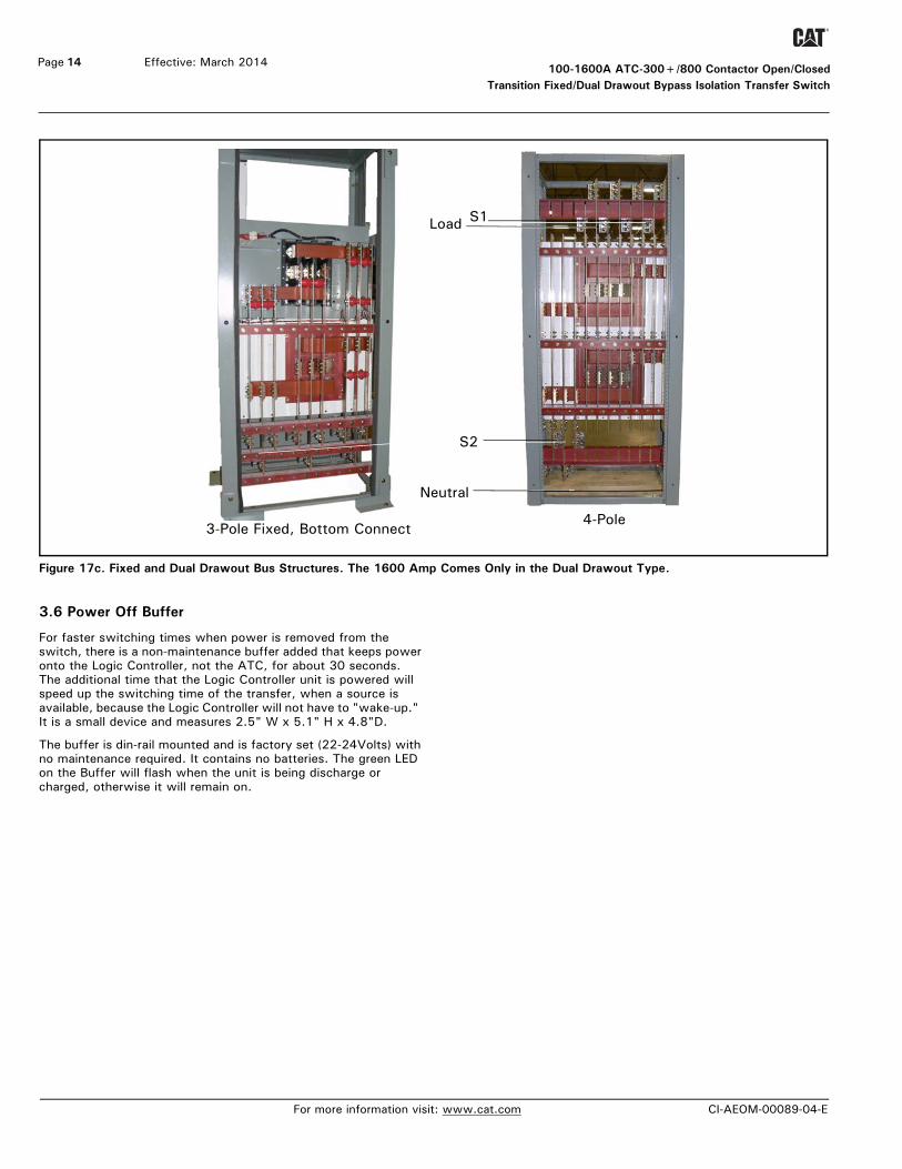
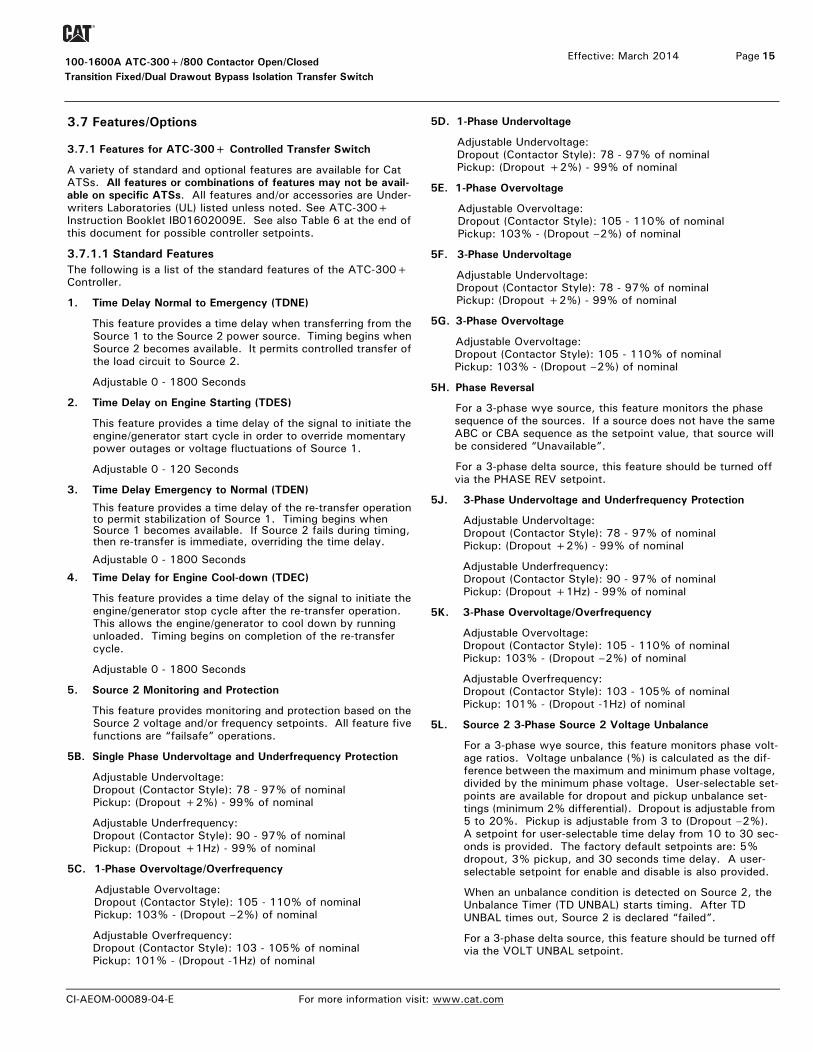
3.5 Neutrals and Bus StructureAll 2-pole and 3-pole transfer switches are equipped with 100% rated solid neutral connections. Figure 17a shows the bottom interconnect bus configuration for the Fixed Bypass Isolation Switch. The connections are also available at the top instead of the bottom. The pictures show a 3-pole switch. Figure 17b shows pictures of the neutral and the ground connections. The bus is also marked with S1, S2, and neutral. The 4-pole would have neu-tral on the rear copper. Figure 17c shows pictures of the Dual Dra-wout bus structures. The Dual Drawout connects can be changed to accommodate all top, all bottom, or a mixture of both. Chang-ing the terminals in the field can be accomplished with directions in Section 4.5.With a standard Dual Drawout type, S1 and Load are shipped on Top and S2 is shipped on the bottom.
Figure 17.
Figure 17a. 3 Pole Fixed Switch Configurations (600-1200A).
Figure 17b. Neutral and Ground Copper.
Bottom
Load
S1
Neutral
S2
3-Pole
Ground Copper
Neutral
CI-AEOM-00089-04-E For more information visit: www.cat.com
Page 14 Effective: March 2014 100-1600A ATC-300+/800 Contactor Open/ClosedTransition Fixed/Dual Drawout Bypass Isolation Transfer Switch
Figure 17c. Fixed and Dual Drawout Bus Structures. The 1600 Amp Comes Only in the Dual Drawout Type.
3.6 Power Off Buffer
For faster switching times when power is removed from the switch, there is a non-maintenance buffer added that keeps power onto the Logic Controller, not the ATC, for about 30 seconds. The additional time that the Logic Controller unit is powered will speed up the switching time of the transfer, when a source is available, because the Logic Controller will not have to "wake-up." It is a small device and measures 2.5" W x 5.1" H x 4.8"D.
The buffer is din-rail mounted and is factory set (22-24Volts) with no maintenance required. It contains no batteries. The green LED on the Buffer will flash when the unit is being discharge or charged, otherwise it will remain on.
Load S1
Neutral
S2
4-Pole3-Pole Fixed, Bottom Connect
For more information visit: www.cat.com CI-AEOM-00089-04-E
Effective: March 2014 Page 15100-1600A ATC-300+/800 Contactor Open/ClosedTransition Fixed/Dual Drawout Bypass Isolation Transfer Switch
3.7 Features/Options
3.7.1 Features for ATC-300+ Controlled Transfer Switch
A variety of standard and optional features are available for Cat ATSs. All features or combinations of features may not be avail-able on specific ATSs. All features and/or accessories are Under-writers Laboratories (UL) listed unless noted. See ATC-300+ Instruction Booklet IB01602009E. See also Table 6 at the end of this document for possible controller setpoints.
3.7.1.1 Standard FeaturesThe following is a list of the standard features of the ATC-300+ Controller.
1. Time Delay Normal to Emergency (TDNE)
This feature provides a time delay when transferring from the Source 1 to the Source 2 power source. Timing begins when Source 2 becomes available. It permits controlled transfer of the load circuit to Source 2.
Adjustable 0 - 1800 Seconds
2. Time Delay on Engine Starting (TDES)
This feature provides a time delay of the signal to initiate the engine/generator start cycle in order to override momentary power outages or voltage fluctuations of Source 1.
Adjustable 0 - 120 Seconds
3. Time Delay Emergency to Normal (TDEN)
This feature provides a time delay of the re-transfer operation to permit stabilization of Source 1. Timing begins when Source 1 becomes available. If Source 2 fails during timing, then re-transfer is immediate, overriding the time delay.
Adjustable 0 - 1800 Seconds
4. Time Delay for Engine Cool-down (TDEC)
This feature provides a time delay of the signal to initiate the engine/generator stop cycle after the re-transfer operation. This allows the engine/generator to cool down by running unloaded. Timing begins on completion of the re-transfer cycle.
Adjustable 0 - 1800 Seconds
5. Source 2 Monitoring and Protection
This feature provides monitoring and protection based on the Source 2 voltage and/or frequency setpoints. All feature five functions are “failsafe” operations.
5B. Single Phase Undervoltage and Underfrequency Protection
Adjustable Undervoltage:Dropout (Contactor Style): 78 - 97% of nominalPickup: (Dropout +2%) - 99% of nominal
Adjustable Underfrequency:Dropout (Contactor Style): 90 - 97% of nominalPickup: (Dropout +1Hz) - 99% of nominal
5C. 1-Phase Overvoltage/Overfrequency
Adjustable Overvoltage:Dropout (Contactor Style): 105 - 110% of nominalPickup: 103% - (Dropout –2%) of nominal
Adjustable Overfrequency:Dropout (Contactor Style): 103 - 105% of nominalPickup: 101% - (Dropout -1Hz) of nominal
5D. 1-Phase Undervoltage
Adjustable Undervoltage:Dropout (Contactor Style): 78 - 97% of nominalPickup: (Dropout +2%) - 99% of nominal
5E. 1-Phase Overvoltage
Adjustable Overvoltage:Dropout (Contactor Style): 105 - 110% of nominalPickup: 103% - (Dropout –2%) of nominal
5F. 3-Phase Undervoltage
Adjustable Undervoltage:Dropout (Contactor Style): 78 - 97% of nominalPickup: (Dropout +2%) - 99% of nominal
5G. 3-Phase Overvoltage
Adjustable Overvoltage:Dropout (Contactor Style): 105 - 110% of nominalPickup: 103% - (Dropout –2%) of nominal
5H. Phase Reversal
For a 3-phase wye source, this feature monitors the phase sequence of the sources. If a source does not have the same ABC or CBA sequence as the setpoint value, that source will be considered “Unavailable”.
For a 3-phase delta source, this feature should be turned off via the PHASE REV setpoint.
5J. 3-Phase Undervoltage and Underfrequency Protection
Adjustable Undervoltage:Dropout (Contactor Style): 78 - 97% of nominalPickup: (Dropout +2%) - 99% of nominal
Adjustable Underfrequency:Dropout (Contactor Style): 90 - 97% of nominalPickup: (Dropout +1Hz) - 99% of nominal
5K. 3-Phase Overvoltage/Overfrequency
Adjustable Overvoltage:Dropout (Contactor Style): 105 - 110% of nominalPickup: 103% - (Dropout –2%) of nominal
Adjustable Overfrequency:Dropout (Contactor Style): 103 - 105% of nominalPickup: 101% - (Dropout -1Hz) of nominal
5L. Source 2 3-Phase Source 2 Voltage Unbalance
For a 3-phase wye source, this feature monitors phase volt-age ratios. Voltage unbalance (%) is calculated as the dif-ference between the maximum and minimum phase voltage, divided by the minimum phase voltage. User-selectable set-points are available for dropout and pickup unbalance set-tings (minimum 2% differential). Dropout is adjustable from 5 to 20%. Pickup is adjustable from 3 to (Dropout –2%). A setpoint for user-selectable time delay from 10 to 30 sec-onds is provided. The factory default setpoints are: 5% dropout, 3% pickup, and 30 seconds time delay. A user-selectable setpoint for enable and disable is also provided.
When an unbalance condition is detected on Source 2, the Unbalance Timer (TD UNBAL) starts timing. After TD UNBAL times out, Source 2 is declared “failed”.
For a 3-phase delta source, this feature should be turned off via the VOLT UNBAL setpoint.
CI-AEOM-00089-04-E For more information visit: www.cat.com
Page 16 Effective: March 2014 100-1600A ATC-300+/800 Contactor Open/ClosedTransition Fixed/Dual Drawout Bypass Isolation Transfer Switch
6. Test Operators
Cat ATSs are provided with a Test Pushbutton that simu-lates a loss of the Source 1 power source as standard (Fea-ture 6B). All programmed time delays (TDNE, TDEN, etc.) will be performed as part of the Test. Engine run time of the Test is equal to the Plant Exerciser (Feature 23) pro-grammed setpoint. All Tests are Failsafe protected.
6B. Test Pushbutton
Programmable setpoints include:
1. Load, No Load Testing, or Disabled; and2. Engine run time is equal to the Plant Exerciser
(Feature 23) setting.
7. Time Delay Emergency Fail (TDEF)
This feature provides a time delay that prevents a con-nected emergency source from being declared “failed” in order to override momentary generator fluctuations. If the Source 2 power source remains in the failed state then, 0.5 seconds after the TDEF timer expires, the transfer switch will proceed with the programmed sequence for re-transfer. This time delay is only implemented when the Source 2 power source is a generator.
Adjustable 0 - 6 Seconds
8. Time Delay Bypass Pushbutton
This feature provides a way (by pushing the Help and Step pushbutton simultaneously) to bypass the TDNE (Feature 1) and/or TDEN (Feature 2) time delays. The Time Delay Bypass function, when activated by pushing the Help and Step pushbutton simultaneously, will reduce any or all of the programmed time delay to zero.
8C. Bypass TDEN
This feature provides a membrane pushbutton to bypass the TDEN time delay.
8D. Bypass TDNE
This feature provides a membrane pushbutton to bypass the TDNE time delay.
12. Power Source Annunciation
This feature provides LEDs to give switch position and power source availability indications.
Switch Position
Provides LEDs to indicate the switch position.
12C. Source 1 - Source Connected
This feature provides an LED that, when lit, indicates the load is connected to Source 1.
12D. Source 2 - Source Connected
This feature provides an LED that, when lit, indicates the load is connected to Source 2.
Power Source Availability
Provides LEDs to indicate if a power source is available. LEDs may be integral or separate from the controller.
12G. Source 1 - Available
This feature provides an LED that, when lit, indicates Source 1 is available.
12H. Source 2 - Available
This feature provides an LED that, when lit, indicates Source 2 is available.
14. Relay Auxiliary Contacts: This feature provides form “C” relay auxiliary contacts
14G. Source 1 Present: Provides two (2) normally open and two (2) normally closed contacts. The relay is energized when Source 1 is available.
14H. Source 2 Present: Provides two (2) normally open and two (2) normally closed contacts. The relay is energized when Source 2 is available.
15E & F. Switch Position Indication Contact
This standard feature provides a contact that indicates if the power-switching device is in the “Open” or “Closed” position for S1 and S2. It is available for the ATS and the Bypass contactors.
15G & H. Switch Position 3 Form C
This optional feature provides three Dry Form “C” contacts that indicates the position of the Source 1 and Source 2 power-switching device.
23. Plant Exerciser (PE)
This feature provides a means for automatic testing of the engine/generator set or standby power system. All pro-grammed time delays will be performed during plant exer-ciser operations.
23K. Plant Exerciser Selectable – Disabled/1/7/14/28 Day Inter-val
This feature provides for automatic test operation of the generator. Available test cycles are daily, 7, 14, or 28 days with duration equal to the programmed engine test time.
Programmable setpoints allow for selection of three test cycles:
• Engine Start/Run Only (No Load);• Exercise with Load Transfer; or Disabled• This is a “Failsafe” operation.
26. Source 1 - Monitoring and Protection
This feature provides Source 1 monitoring and protection functions. If the Source 1 power supply fails, then the ATC-300+ will begin the sequence of operations neces-sary to transfer the load circuit to the Source 2 power source. All Feature 26 monitoring and protection functions are “failsafe” operations.
26A. All Phase Undervoltage Protection
This feature provides all phase undervoltage monitoring and protection.
Adjustable Undervoltage:Dropout (Contactor Style): 78 - 97% of nominalPickup: (Dropout +2%) - 99% of nominal
For more information visit: www.cat.com CI-AEOM-00089-04-E
Effective: March 2014 Page 17100-1600A ATC-300+/800 Contactor Open/ClosedTransition Fixed/Dual Drawout Bypass Isolation Transfer Switch
26C. All Phase Overvoltage Protection
Provides all phase overvoltage monitoring and protection.
Adjustable Overvoltage:Dropout (Contactor Style): 105-110% of nominal Pickup: 103% - (Dropout -2%) of nominal
26D. Go to Source 2
This feature provides the capability for an external contact opening to initiate a load power transfer to the Source 2 power source. This includes starting the engine/generator, performing the programmed time delays, and the transfer operation. Re-transfer will occur when the external contact is closed or under a “failsafe” condition. A connection point on the controller for the connection of an external contact is included.
26E. All Phase Underfrequency Protection
Provides all phase underfrequency monitoring and protec-tion.
Adjustable Underfrequency:Dropout: 90-97% of nominalPickup: (Dropout +1Hz) - 99% of nominal
26F. All Phase Overfrequency Protection
Provides all phase overfrequency monitoring and protection.
Adjustable Overfrequency:Dropout (Contactor Style): 103 - 105% of nominalPickup: 101% - (Dropout -1Hz) of nominal
26H. Phase Reversal Protection
For a 3-phase wye source, this feature monitors the phase sequence of the sources. If a source does not have the same ABC or CBA sequence as the phase reversal setpoint, the source will be considered “Unavailable”.
For a 3-phase delta source, this feature should be turned off via the PHASE REV setpoint.
26L. Source 1 3-Phase Voltage Unbalance
For a 3-phase wye source, this feature monitors phase volt-age ratios. Voltage unbalance (%) is calculated as the dif-ference between the maximum and minimum phase voltage, divided by the minimum phase voltage. User-selectable set-points are available for dropout and pickup unbalance set-tings (minimum 2% differential). Dropout is adjustable from 5 to 20%. Pickup is adjustable from 3 to (Dropout –2%). A setpoint for user-selectable time delay from 10 to 30 sec-onds is provided. The factory default setpoints are: 5% dropout, 3% pickup, and 30 seconds time delay. A user-selectable setpoint for enable and disable is also provided.
When an unbalance condition is detected on Source 1, the Unbalance Timer (TD UNBAL) starts timing. After TD UNBAL times out, Source 1 is declared “failed”.
For a 3-phase delta source, this feature should be turned off via the VOLT UNBAL setpoint.
29. Alternate Transfer Modes of Operation
Provides standard or optional transfer modes, mode selec-tion devices, and operational methods for ATSs.
29A. Automatic Operation
Provides fully automatic transfer, re-transfer, and engine/generator startup and shutdown operations.
29D. Dual ATS for Fixed Bypass
This patented feature allows for the controller (ATC-300+ or ATC-800) to be active when the switch is in the bypass position. Therefore the switch has a redundant feature for automatic switching in open transition.
32. Delayed Transition Transfer Modes for Open Transition Transfer Switches
This feature provides delayed transition transfer modes for an open transition transfer switch. Often used in systems with inductive loads, a delayed transition transfer switch may prevent or reduce in-rush currents due to out of phase switching of inductive loads.
32A. Time Delay Neutral
This feature provides a time delay in the transfer switch Neutral position when both the source one and source two contacts are open. This delay takes place when the load is transferred in either direction to prevent excessive in-rush currents due to out-of-phase switching of large motor loads. This feature is not available with the Neutral Load Sense Delay (TDNLD) feature.
Adjustable 0 - 120 Seconds
35. Pre-Transfer Signal
This feature provides a signal to a remote device prior to a re-transfer operation. It provides one (1) Form “C” contact (NO/NC) for interface with other equipment (typically eleva-tor controls). The contacts close/open on a timed basis prior to transfer in either direction. After TDNE/TDEN times out, this relay closes and the Pre-transfer Timer (TPRE) starts timing. After the TPRE times out, the transfer pro-ceeds by starting the TDN timer if enabled. The pre-transfer relay opens after the transfer is complete.
Adjustable 0 - 120 Seconds
35A. Pre-transfer Signal with 1 N.O. and 1 N.C. Contacts
This feature provides pre-transfer signal and includes one (1) N.O. and one (1) N.C. contact.
Emergency Inhibit
This feature enables the Emergency Inhibit control input to inhibit transfers to the Emergency Source. See the Control Inputs section for more information.
42. Seismic Qualified
59A. Silver Plated Bus
3.7.1.2 Optional Features
The following is a list of the optional features for the ATC-300+ Controlled ATS. All features or combinations of features may not be available on specific ATSs
18. Metering and Communications
Metering options include all required external devices (CTs, etc.) for a fully functioning metering system.
CI-AEOM-00089-04-E For more information visit: www.cat.com
Page 18 Effective: March 2014 100-1600A ATC-300+/800 Contactor Open/ClosedTransition Fixed/Dual Drawout Bypass Isolation Transfer Switch
21. Optional Power Cable Connection Terminals
Cat Transfer Switches are provided as standard with Source 1, Source 2, and Load Circuit solderless screw-type terminals for power cable connection. Alternate terminal wire sizes may be available dependant on transfer switch type and ampere rating.
21A. Optional Power Cable Connection TerminalsThis feature provides alternate power cable connection ter-minals. Consult Caterpillar for available optional terminal sizes.
32D. Optional In-Phase with Default to Time Delay Neutral This feature provides an in-phase transfer with a default to a time delay neutral transfer which ensures that the ATS will complete a transfer whether or not the two live sources can synchronize. When in-phase with default to time delay in neutral is set and source synchronization does not occur in the specified amount of time, the transfer will default to a time delay in neutral transfer and the Alarm relay will ener-gize and the failure will be logged into the Transfer History as either “Sync Fail - Freq” or “Sync Fail - Phase” depending on whether the frequency difference or the phase difference was excessive. This option allows the user to configure the switch in the field to be In-Phase only, Time Delay Neutral only, or In-Phase with default to TDN (factory setting).
32F. Optional In-phase TransitionAn In-phase transfer is an open transition transfer that pre-vents in-rush currents from exceeding normal starting cur-rents in the case where motor loads are being transferred. An In-Phase Monitor transition will permit a transfer or re-transfer between two live sources that have a frequency difference less than the in-phase transition frequency set-point of 0.0 - 3.0Hz. Once this condition is met the ATC-800 will monitor the phase difference between the two sources. The synchronization timer (0-60 minutes) will count down and be displayed as “TSIP” while waiting for synchronization to be detected. When the phase difference is within the advance angle window (8 degrees or less), the “transfer” command is given. If the synchronization does not occur within a specified amount of time, the transfer will either be aborted pending user intervention and the Alarm relay will energize and the failure will be logged into the Transfer History as either “Sync Fail - Freq” or “Sync Fail - Phase” depending on whether the frequency differ-ence or the phase difference was excessive
38B. Stainless Steel Cover for ControllerProvides an added level of security by providing a pad lock-able stainless steel cover for use with standard transfer switch logic controllers and/or associated device panels. These covers function with Cat’s ATC series logic control-lers and device panels. The covers are designed for NEMA 1, 3R, 4X, and 12 applications.
41. Space Heater With ThermostatThis feature provides a space heater and non-adjustable thermostat. External control power is not required.
41A. Space Heater With Thermostat - 100 WattThis feature provides a 100 watt (W) space heater with a non-adjustable thermostat.
48F. RS-485 with Modbus OptionProvides communications for the ATC-300+ via Modbus through an integrated RS-485 port. Registers are available to read back status, voltages, frequencies, and historical data.
Registers are also available for transfer switch control. Set-points may be read back and/or programmed via a passthrough command. See the ATC-300+ Modbus Com-munication Guide pn: 66A7787.
49C. Multi-Tap Transformer
51x. Various Cat Series SPD type surge devices.
3.7.2 Features for ATC-800 Controlled Transfer SwitchThe primary function of ATC-800 is to accurately monitor power sources and provide the necessary intelligence to operate a trans-fer switch in an appropriate and timely manner. In addition, the ATC-800 provides useful present and historical data, reliable two-way communications, and programming through the device’s faceplate or communications option. The ATC-800 features propri-etary microprocessor technology to provide and maintain superior precision and versatility during both programming and data access.
3.7.2.1 Operational SimplicityFrom installation to programming to usage, the ATC-800 was designed with operational simplicity in mind. Only one style needs to be considered, regardless of input/output requirements or sys-tem voltages and frequencies. The ATC-800 provides the func-tionality of numerous other devices combined in one package that mounts in less than 7 x 11 in. (177.8 x 279.4 mm) of panel space.The user friendly front panel interface simplifies routine operation, programming, data presentation and setting adjustments. An LED based display provides the flexibility of large character displays for enhanced visibility. The operation of front panel membrane push-buttons moves the ATC-800 display from function to function or step to step within a function. LEDs at the top of the faceplate pro-vide an immediate indication as to the device’s operational mode. An integral Help Mode provides immediate user assistance in the form of English language message displays through the use of a front panel Help pushbutton.With a Product Operated Network Interface (PONI), the ATC-800 is communications ready and compatible with other devices in the IQ Family of products. The Communication Module (PONI) is avail-able in two versions, the INCOM PONI, and the Modbus PONI. Reliable two-way communications can be provided over a twisted pair communications network. The ATC-800 is compatible with the Cat Power Expert Architecture.
3.7.2.2 Standard and Optional FeaturesA variety of programmable features are available to meet a wide variety of application requirements. Individual features or feature combinations provide the intelligence required to tailor switches to individual needs.The features are factory activated, depending upon customer requirements. The specific variable setpoints associated with stan-dard and factory activated features are stored in a nonvolatile memory. Activated feature setpoints are available for customer adjustment. Any feature not selected and factory activated cannot be viewed or adjusted.
NOTICEWITH RESPECT TO THEIR USE IN THIS DOCUMENT AND AS THEY RELATE TO AUTOMATIC TRANSFER SWITCH OPERATION, THE FOL-LOWING WORDS OR PHRASES ARE DEFINED:
For more information visit: www.cat.com CI-AEOM-00089-04-E
Effective: March 2014 Page 19100-1600A ATC-300+/800 Contactor Open/ClosedTransition Fixed/Dual Drawout Bypass Isolation Transfer Switch
AvailableA source is defined as available when it is within its undervoltage/overvoltage/underfrequency/overfrequency (if applicable) setpoint ranges for the nominal voltage and frequency setting.
Fails A source is defined as failed when it is outside of its undervoltage/overvoltage/underfrequency/overfrequency (if applicable) setpoint ranges for the nominal voltage and frequency setting.
Normal SourceThe Normal Source is defined as the source that is preferred. The Preferred Source setting allows the operator to select Source 1, Source 2, or NONE as the Preferred Source. If NONE is chosen, the Preferred Source or the Normal Source will be the source that is presently attached to the load. If the Preferred Source feature is not available from the factory, the default is set as being Source 1 as the Preferred and Normal Source.
Emergency SourceThe Emergency Source is defined as the source that is not pre-ferred. If NONE is chosen for the Preferred Source setting, the Emergency Source will be the source that is presently not attached to the load. Therefore, in this condition after a transfer, what was the Normal and Emergency Sources will switch between Source 1 and 2. If the Preferred Source feature is not available from the factory, the default is set with Source 2 as the Emergency Source.
For personnel who are familiar with previous transfer switch con-troller option specifications, an attempt at equivalence to some of the features is made.ATC-800 features with a brief description follow.
Standard Feature: Time Delay Engine Start (TDES) TDES is used where the source is an engine generator. It delays initiation of the engine start circuit in order to override momentary power outages and/or fluctuations. This timer and the associated engine start circuit will operate with or without control power. There are two separate start circuits, one for each source when applications of two generators are selected, although the same TDES timer value is used for both. When one generator is selected, this timer’s engine start circuit will operate on generator 2 for Source 2. If the source that is being transferred to has a gen-erator and that source is already available, the TDES timer is bypassed.
Standard Feature: Time Delay Normal to Emergency (TDNE) TDNE delays the transfer to the Emergency Source to permit sta-bilization of the Emergency power source before the transfer is made. This timer will begin the countdown from its setting value when the Emergency Source becomes available. If the Normal Source should become available during the countdown of this timer, the timer will be aborted.
Standard Feature: Time Delay Emergency to Normal (TDEN) TDEN delays the transfer to the Normal Source to permit stabiliza-tion of the Normal power source before the transfer is made. This timer will begin the countdown from its setting value when the Normal Source becomes available. During the countdown of this timer, if the Normal Source should become unavailable, the timer will be aborted. If the Preferred Source is available and the Emer-gency Source fails while the TDEN timer is counting down, the TDEN timer will be bypassed.
Standard Feature: Time Delay for Engine Cool-Off (TDEC) TDEC permits the generator to run under a no-load condition after a transfer from the generator source has been made. Countdown timing begins when the transfer is completed. In applications where two generators are selected, the same cool-off timer set-ting value is used for both.
Standard Feature: Time Delay Emergency Failure (TDEF) TDEF is used where at least one source is an engine generator. TDEF will delay an available source from being declared unavail-able in order to override momentary generator fluctuations. This time delay is only implemented when the load is connected to a generator source. TDEF is not displayed when the number of gen-erators is zero.
Standard Feature: System Nominal Frequency (NOMF) There are only two choices for system nominal frequency of the distribution system, 50 or 60 Hertz. The dropout/pickup, underfre-quency and overfrequency upper and lower setting limits are based on the nominal frequency value.
Standard Feature: System Nominal Voltage (NOMV) This refers to the standard system nominal RMS line to line volt-age. A wide range (120 to 600) of sensing voltage is available to be programmed. The dropout/pickup, undervoltage and overvolt-age upper and lower setting limits are based upon the nominal voltage value.
Standard Feature: Undervoltage Monitoring for Source 1 (1UVD, 1UVP) This feature constantly monitors Source 1 for an undervoltage condition. When the Source 1 voltage drops to a value equal to or below the undervoltage dropout setting, the source will become unavailable. The source’s voltage will then have to rise to a value that is equal to or above the pickup setting to become available again.
Standard Feature: Undervoltage Monitoring for Source 2 (2UVD, 2UVP) This feature functions the same as Standard Feature (1UVD, 1UVP), except for Source 2 instead of Source 1.
Standard Feature: Underfrequency Monitoring for Source 2 (2UFD, 2UFP)This feature functions the same as Optional Feature 26E, except for Source 2 instead of Source 1.
Standard Feature: Commit to Transfer During TDNE Timing (CTDNE)This feature provides for selection as to whether or not commit-ment to transfer is desired when Time Delay Normal to Emergency countdown has begun. If no commitment is chosen and the Nor-mal Source returns to availability when the TDNE timer is counting down, the transfer is aborted and the engine generator (if applica-ble) is cooled down.
CAUTIONCHANGING THE SYSTEM NOMINAL VOLTAGE OR FREQUENCY SET-POINTS WILL CAUSE PICKUP AND DROPOUT SETPOINTS TO CHANGE AUTOMATICALLY TO NEW DEFAULT VALUES.
CI-AEOM-00089-04-E For more information visit: www.cat.com
Page 20 Effective: March 2014 100-1600A ATC-300+/800 Contactor Open/ClosedTransition Fixed/Dual Drawout Bypass Isolation Transfer Switch
Standard Feature: Engine Test Mode (TMODE)This feature provides selection of the type of test that can be initi-ated by the front panel Engine Test pushbutton. An engine test without transferring the load to it, or an engine test with a full transfer of the load to the engine can be chosen. Load testing is fail-safe. If the generator fails during testing for any reason, the ATC-800 will signal the transfer switch to return to normal. If dis-able test mode is chosen, the front panel pushbutton cannot be used to initiate a test.
Standard Feature: Test Engine Run (TER)This feature provides selection of the length of time in hours and minutes that the ATC-800 will enable the generator contacts dur-ing an Engine Test that was initiated from the front panel pushbut-ton or for the plant exerciser feature, if applicable.
Standard Feature 5C: Overfrequency Monitoring for Source 2 (2OFD, 2OFP)This feature constantly monitors Source 2 for an overfrequency condition. When the Source 2 frequency rises to a value equal to or above the overfrequency dropout setting, the source will become unavailable. The source’s frequency will then have to drop to a value that is equal to or below the pickup setting to become available again.
Standard Feature 8C/8D: Transfer Time Delay BypassThis feature allows an external pushbutton input to be used to bypass the timer for Standard Feature (TDNE) or Standard Feature (TDEN) individually, or both simultaneously. This feature is usually used in testing when it is not desirable to wait for completion of the timing sequence.
Standard Feature 23: Plant Exerciser (EXER)This feature provides for the automatic test operation of the gen-erator for a pre-selected weekly interval. When the test is running, pressing and releasing the Engine Test pushbutton will cancel the test. The day of the week, hour, and minute that exercising is desired can be programmed into the ATC-800. The type of test, whether a load transfer or just an engine test, can also be selected. Load testing is fail-safe. If the generator fails during test-ing for any reason, the ATC-800 will signal the transfer switch to return to normal.
Standard Feature 26C: Overvoltage Monitoring for Source 1 (1OVD, 1OVP) This feature constantly monitors Source 1 for an overvoltage con-dition. When the Source 1 voltage rises to a value equal to or above the overvoltage dropout setting, the source will become unavailable. The source’s voltage will then have to drop to a value that is equal to or below the pickup setting to become available again.
Standard Feature 26D: Go To Emergency This feature enables an external contact closure to initiate a trans-fer from the Normal Source to the Emergency Source. If the external contact is closed and the Emergency Source fails, the ATC-800 will transfer the load back to the Normal Source.
Standard Feature 26E: Underfrequency Monitoring for Source 1 (1UFD, 1UFP) This feature constantly monitors Source 1 for an underfrequency condition. When the Source 1 frequency drops to a value equal to or below the underfrequency dropout setting, the source will become unavailable. The source’s frequency will then have to rise to a value that is equal to or above the pickup setting to become available again.
Standard Feature 26F: Overfrequency Monitoring for Source 1 (1OFD, 1OFP) This feature constantly monitors Source 1 for an overfrequency condition. When the Source 1 frequency rises to a value equal to or above the overfrequency dropout setting, the source will become unavailable. The source’s frequency will then have to drop to a value that is equal to or below the pickup setting to become available again.
Standard Feature 36: Emergency Inhibit This feature enables the Emergency Inhibit control input to inhibit transfers to the Emergency Source. See the Control Inputs section for more information.
Optional Features
Optional Feature 5E: Overvoltage Monitoring for Source 2 (2OVD, 2OVP) This feature constantly monitors Source 2 for an overvoltage con-dition. When the Source 2 voltage rises to a value equal to or above the overvoltage dropout setting, the source will become unavailable. The source’s voltage will then have to drop to a value that is equal to or below the pickup setting to become available again.
Optional Features 5H, 5L, 26H, 26L: Phase Reversal, Phase Volt-age Unbalance, and Phase LossPhase Reversal, Phase Voltage Unbalance, and Phase Loss for S1 (5H, 5L) and S2 (26H, 26L) require external hardware for the ATC-800 controller.
Optional Feature 10: Preferred Source Selection (PRF SRC) This feature permits the selection of either source (1 or 2) as the Preferred or Normal Source. The Normal Source is the source that the switch always looks to for availability so that it can transfer to it. When two generators are selected and the switch has trans-ferred to the Emergency Source, the ATC-800 will constantly be waiting and attempting to start the generator on the Preferred Source so that it may return to it. IF NONE is chosen, the Pre-ferred Source or the Normal Source will be the source that is pres-ently attached to the load.
Optional Feature 29G: Type of Operation (Selectable Automatic or Manual)This feature provides a third position on the Auto and Bypass to allow for Electrical close and open on the ATS contactor. The controller is in lockout or Non-Auto mode during this process. It permits the selection of automatic or manual operation on the ATS bottom contactor.
Optional Feature 29J: Type of Operation (MANTR) This feature provides for a selection between an automatic trans-fer and re-transfer mode or a manual pushbutton re-transfer to Normal from the Emergency Source mode. If this option is not selected the factory default selection is automatic.
For more information visit: www.cat.com CI-AEOM-00089-04-E
Effective: March 2014 Page 21100-1600A ATC-300+/800 Contactor Open/ClosedTransition Fixed/Dual Drawout Bypass Isolation Transfer Switch
Optional Feature 32A: Time Delay Neutral (TDN)This feature provides a time delay in the transfer switch Neutral position when both the source one and source two contacts are open. This delay takes place when the load is transferred in either direction to prevent excessive in-rush currents due to out-of-phase switching of large motor loads. This feature is not available with the Neutral Load Sense Delay (TDNLD) feature.
Optional Feature 32B: Load Voltage Decay (LDCY) This feature utilizes the load voltage measurements to sense back EMF that is generated when the transfer switch is in the Neutral position. It provides a delay in transfer in either direction if an unacceptable level is sensed as established by a customer pro-grammed level. The transfer will not take place until the back EMF decays below the acceptable programmed level. This feature has a separate setting of enabling or disabling the operation. If disabled, the transfer switch will not delay in the Neutral position and will transfer between the sources as fast as possible. This feature is not available with the Time Delay Neutral (TDN) Feature 32A.
Optional Feature 32D: In-Phase with Default to Time Delay NeutralThis feature provides an in-phase transfer with a default to a time delay neutral transfer which ensures that the ATS will complete a transfer whether or not the two live sources can synchronize. When in-phase with default to time delay in neutral is set and source synchronization does not occur in the specified amount of time, the transfer will default to a time delay in neutral transfer and the Alarm relay will energize and the failure will be logged into the Transfer History as either “Sync Fail - Freq” or “Sync Fail - Phase” depending on whether the frequency difference or the phase difference was excessive. This option allows the user to configure the switch in the field to be In-Phase only, Time Delay Neutral only, or In-Phase with default to TDN (factory setting).
Optional Feature 32F: In-phase TransitionAn In-phase transfer is an open transition transfer that prevents in-rush currents from exceeding normal starting currents in the case where motor loads are being transferred. An In-Phase Monitor transition will permit a transfer or re-transfer between two live sources that have a frequency difference less than the in-phase transition frequency setpoint of 0.0 - 3.0Hz. Once this condition is met the ATC-800 will monitor the phase difference between the two sources. The synchronization timer (0-60 minutes) will count down and be displayed as “TSIP” while waiting for synchroniza-tion to be detected. When the phase difference is within the advance angle window (8 degrees or less), the “transfer” com-mand is given. If the synchronization does not occur within a specified amount of time, the transfer will either be aborted pend-ing user intervention and the Alarm relay will energize and the fail-ure will be logged into the Transfer History as either “Sync Fail - Freq” or “Sync Fail - Phase” depending on whether the frequency difference or the phase difference was excessive
Optional Feature 35: Pre-Transfer Signal (TPRE)Typically associated with elevator controls, this feature provides for the control of an addressable relay to remotely signal an eleva-tor that a re-transfer is about to take place. A permissive report-back signal from the elevator, telling the ATC-800 that the eleva-tor has reached the floor and opened its doors, is also recognized to facilitate faster transfer operation. Should the permissive signal not be used or does not occur, the ATC-800 has a programmed overriding pre-transfer delay timer that can be set from 0 to 5 min-utes.
Optional Feature 37: Service Equipment This factory programmed feature makes the transfer switch suit-able for a service equipment rating by responding to a Go-To-Neu-tral input.
Optional Feature 45: Load Sequencing Capability (TSEQ)This feature provides the sequential closure of up to ten (10) remote relays after a transfer. A customer programmed time delay is available to delay closure between each of the relays.
Optional Feature 46: Potential Transformer (PT) RatioThis feature allows external voltage transformers to be used on the ATC-800’s source and load sense inputs. Once this option is enabled, the PT Ratio setpoint can be adjusted in steps of 1, between 2:1 and 500:1. Also, when this option is enabled, the Nominal System Voltage setting will be fixed at 120 or 110 volts, depending upon the Nominal System Frequency setting. If the Nominal System Frequency setting is 60Hz then the Nominal Sys-tem Voltage will be fixed at 120 volts and all voltage pick-up and drop-out setpoints will be based upon the 120 volt level. The same is true of a Nominal System Frequency of 50Hz whose Nom-inal System Voltage will be fixed at 110 volts. The metering dis-play will use the PT ratio value to calculate and display the load and source voltages with up to three significant digits. There will be four possible types of displays, as an example they could dis-play 999K, 99.9K, 9.99K, or 999 volts.
Optional Feature 47, 47F, 47G: Closed Transition (ATC-800)Closed Transition is a feature that will temporarily parallel two live sources in a make-before-break scheme when performing a trans-fer. This achieves a transfer between sources with no power interruption. Both sources must be synchronized in frequency, phase, and voltage before the transfer is initiated.With option 47G, If the logic is forced into a fail safe mode (i.e. loss of connected source), the logic will perform a Time Delay Neutral open transfer 47G is the most common choice. 47F is Closed Transition Load Voltage Decay.
Optional Feature 48: Communication ModulesProvides communications modules for the ATC-800 transfer switch controllers. These controllers are PowerNet and Modbus compatible devices. A separately mounted communications mod-ule will enable the automatic transfer controller to be remotely monitored controlled and programmed via the network.
48F: RS-485 with ModbusProvides communications for the ATC-800 or Modbus through an RS-485 port. Registers are available to read back status, voltages, frequencies, and historical data. Registers are also available for transfer switch control. Setpoints may be read back and/or pro-grammed via a pass-through command.
There are many other options for these switches such as Phase Unbalanced/Loss, metering, Auto/Manual Operation, Remote Annunciator, Gateways, and Surge devices. Please consult factory for more features and options.
CI-AEOM-00089-04-E For more information visit: www.cat.com
Page 22 Effective: March 2014 100-1600A ATC-300+/800 Contactor Open/ClosedTransition Fixed/Dual Drawout Bypass Isolation Transfer Switch
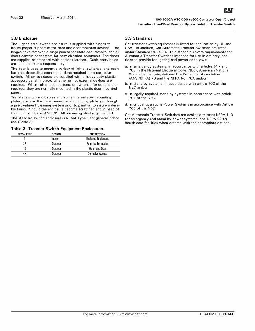
3.8 EnclosureThe rugged steel switch enclosure is supplied with hinges to insure proper support of the door and door mounted devices. The hinges have removable hinge pins to facilitate door removal and all doors contain connectors for easy electrical reconnect. The doors are supplied as standard with padlock latches. Cable entry holes are the customer’s responsibility.The door is used to mount a variety of lights, switches, and push buttons, depending upon the options required for a particular switch. All switch doors are supplied with a heavy duty plastic accessory panel in place, whether or not external devices are required. When lights, pushbuttons, or switches for options are required, they are normally mounted in the plastic door mounted panel. Transfer switch enclosures and some internal steel mounting plates, such as the transformer panel mounting plate, go through a pre-treatment cleaning system prior to painting to insure a dura-ble finish. Should the enclosure become scratched and in need of touch up paint, use ANSI 61. All remaining steel is galvanized.The standard switch enclosure is NEMA Type 1 for general indoor use (Table 3).
Table 3. Transfer Switch Equipment Enclosures.
3.9 StandardsCat transfer switch equipment is listed for application by UL and CSA. In addition, Cat Automatic Transfer Switches are listed under Standard UL 1008. This standard covers requirements for Automatic Transfer Switches intended for use in ordinary loca-tions to provide for lighting and power as follows:
a. In emergency systems, in accordance with articles 517 and 700 in the National Electrical Code (NEC), American National Standards Institute/National Fire Protection Association (ANSI/NFPA) 70 and the NFPA No. 76A and/or
b. In stand-by systems, in accordance with article 702 of the NEC and/or
c. In legally required stand-by systems in accordance with article 701 of the NEC.
d. In critical operations Power Systems in accordance with Article 708 of the NEC
Cat Automatic Transfer Switches are available to meet NFPA 110 for emergency and stand-by power systems, and NFPA 99 for health care facilities when ordered with the appropriate options.
NEMA TYPE DESIGN PROTECTION
1 Indoor Enclosed Equipment
3R Outdoor Rain, Ice Formation
12 Outdoor Water and Dust
4X Outdoor Corrosive Agents
For more information visit: www.cat.com CI-AEOM-00089-04-E
Effective: March 2014 Page 23100-1600A ATC-300+/800 Contactor Open/ClosedTransition Fixed/Dual Drawout Bypass Isolation Transfer Switch
Section 4: Installation and Wiring 4.1 GeneralCat transfer switches are factory wired and tested. Installation requires solidly mounting the enclosed unit and connecting the power cables and auxiliary pilot circuits. Physical mounting proce-dures and power cable connections are covered in this section. All other required wiring or electrical connection references are covered in a separate Customer Wiring Diagram packaged with the transfer switch. Locate the wiring booklet, review it, and keep it readily available for reference purposes during installation and testing. Once a transfer switch is properly installed and wired, it should be mechanically and electrically checked for proper installation and operation. The procedures for these initial mechanical and electri-cal checks are outlined in Section 7 of this instruction manual.
4.2 Mounting LocationChoose a location that offers a flat, rigid mounting surface capa-ble of supporting the weight of the enclosed transfer switch equipment. Avoid locations that are moist, hot, or dusty. How-ever, Cat offers enclosure designs that can be used in special environments. If there are any doubts as to the suitability of the location, discuss it with your Cat dealer.Check to make certain that there are no pipes, wires, or other haz-ards in the immediate area that could create a problem. The pan-els provide ample room for rear cable entry from top, bottom, and sides. At no time should cable be routed to retard the action of relays or cover the logic in a way that restricts adjustments. Maintain proper electrical clearances between live metal parts and grounded metal.For installation and maintenance purposes, the Source 1 and Source 2 power sources must have an overcurrent protective device upstream of the transfer switch, unless overcurrent protec-tion is integral to the switch.The dimensions of the transfer switch are an important consider-ation in determining proper location selection.
4.3 Unpackaging and Inspection
Proceed with the following four steps.
Step 1: Carefully uncrate the transfer switch. If damage is visible, please contact your local Cat dealer or the factory.
Step 2: Open the door by inserting a tool into the bottom door opening and pull up to release the door lever as shown in Figure 18. This method is only used to open the door when the unit is initially shipped and with no power (S1 & S2) to the switch. Visually verify that there are no broken or damaged components or evidence of distorted metal or loose wires as a result of rough handling.
Figure 18. Opening the Door with No Power to the Switch.
Step 3: A label on the door provides specifications for your trans-fer switch. Verify that these specifications comply with your requirements.
Step 4: Remove any braces or packing used to protect the trans-fer switch or internal components during shipping.
4.4 Mounting Procedure
With the enclosed transfer switch equipment unpacked and ready for mounting, proceed with the following steps.
Step 1: Mounting and cabling access is best provided by remov-ing side and rear covers (when applicable). See Section 9.3 for cover removal instructions.
Step 2: Gently maneuver the switch into its location using all of the supplied lift brackets.
WARNINGBE CERTAIN THAT THE STEEL POWER PANEL BARRIERS ARE PROP-ERLY INSTALLED BEFORE THE TRANSFER SWITCH EQUIPMENT IS PUT INTO SERVICE. THE BARRIER PROVIDES PROTECTION FROM DANGEROUS VOLTAGE AT THE LINE AND LOAD TERMINALS WHEN THE EQUIPMENT IS IN OPERATION. FAILURE TO DO SO COULD RESULT IN PERSONAL INJURY OR DEATH.
CAUTIONSINCE THE ENCLOSED TRANSFER SWITCH MUST BE LIFTED INTO PLACE FOR MOUNTING, BE CERTAIN THAT ADEQUATE RESOURCES ARE AVAILABLE FOR LISTING TO AVOID PERSONNEL INJURIES OR EQUIPMENT DAMAGE.
CAUTIONEXTREME CARE SHOULD BE TAKEN TO PROTECT THE TRANSFER SWITCH FROM DRILL CHIPS, FILLINGS, AND OTHER CONTAMI-NANTS WHEN MAKING THE CABLE ENTRY HOLES AND MOUNTING THE ENCLOSURE TO PREVENT COMPONENT DAMAGE OR A FUTURE MALFUNCTION.
NOTICECABLE ENTRY HOLES ARE NOT PART OF THE ENCLOSURE WHEN SHIPPED FROM THE FACTORY AND MUST BE PROVIDED IN THE FIELD, EITHER BEFORE OR AFTER MOUNTING THE ENCLOSURE.
CI-AEOM-00089-04-E For more information visit: www.cat.com
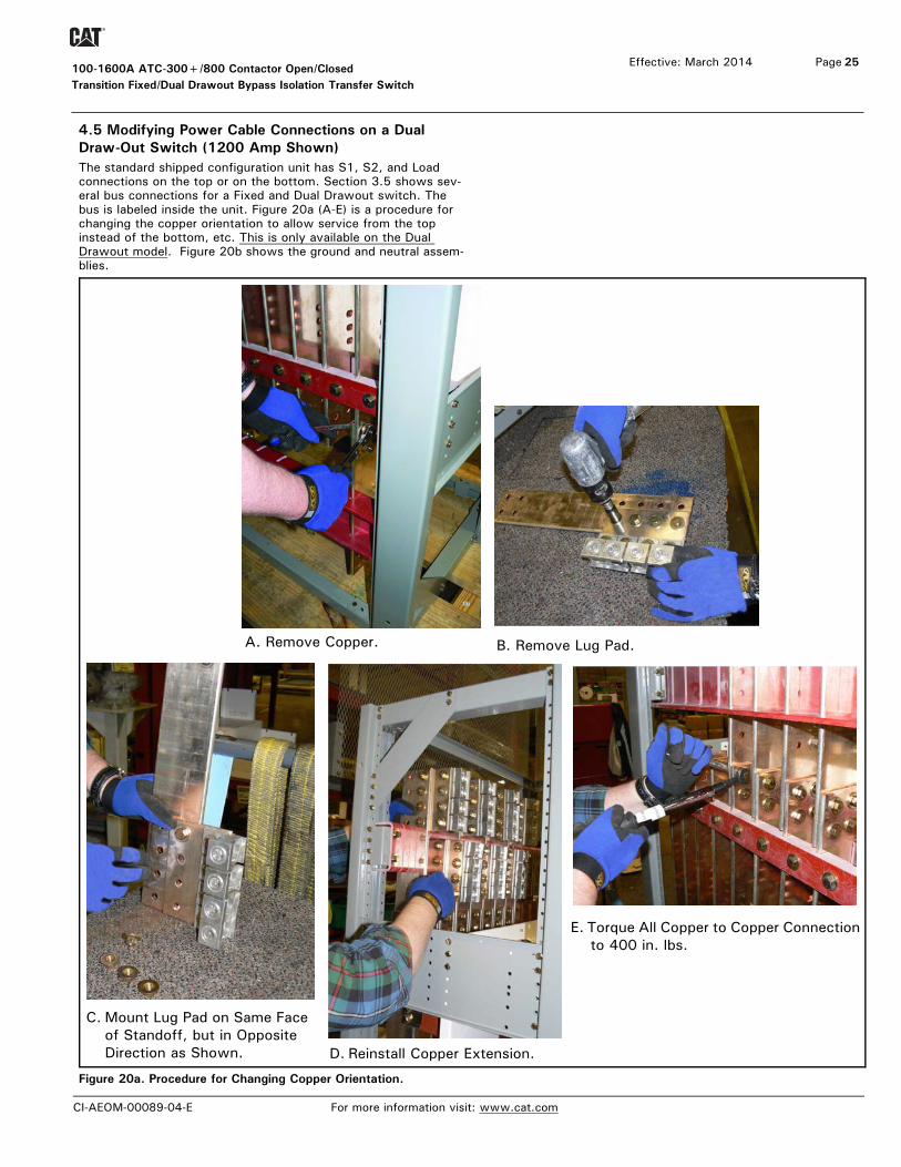
Page 24 Effective: March 2014 100-1600A ATC-300+/800 Contactor Open/ClosedTransition Fixed/Dual Drawout Bypass Isolation Transfer Switch
Step 3: Bolt the enclosure to the base. Use separate seismic washers (Option 42 only) if Seismic Uniform Building Code (UBC) Zone 4 certification is desired (Figure 19a and 19b), and secure with 1/2-13 UNC Grade 5 hex bolts. Fig-ure 19a is using seismic brackets and Figure 19b is using seismic washers. The unit was Seismic tested to 120% of the rating.
Step 4: Tighten bolts to 50 ft-lbs (68 Nm).
Step 5: Double check to ensure that all packing and shipping material has been removed
IT IS NECESSARY TO USE 0.5-13 GRADE 5 OR BETTER HEX HEAD BOLTS, THESE BOLTS ARE TO BE TORQUED TO 50FT/LBS[68NM]
WASHERSEISMIC WASHER
For more information visit: www.cat.com CI-AEOM-00089-04-E
Effective: March 2014 Page 25100-1600A ATC-300+/800 Contactor Open/ClosedTransition Fixed/Dual Drawout Bypass Isolation Transfer Switch
4.5 Modifying Power Cable Connections on a Dual Draw-Out Switch (1200 Amp Shown)The standard shipped configuration unit has S1, S2, and Load connections on the top or on the bottom. Section 3.5 shows sev-eral bus connections for a Fixed and Dual Drawout switch. The bus is labeled inside the unit. Figure 20a (A-E) is a procedure for changing the copper orientation to allow service from the top instead of the bottom, etc. This is only available on the Dual Drawout model. Figure 20b shows the ground and neutral assem-blies.
Figure 20a. Procedure for Changing Copper Orientation.
D. Reinstall Copper Extension.
C. Mount Lug Pad on Same Face of Standoff, but in Opposite Direction as Shown.
A. Remove Copper. B. Remove Lug Pad.
E. Torque All Copper to Copper Connection to 400 in. lbs.
CI-AEOM-00089-04-E For more information visit: www.cat.com
Page 26 Effective: March 2014 100-1600A ATC-300+/800 Contactor Open/ClosedTransition Fixed/Dual Drawout Bypass Isolation Transfer Switch
Figure 20b. Neutral and Ground Copper.
Ground Copper
Neutral
For more information visit: www.cat.com CI-AEOM-00089-04-E
Effective: March 2014 Page 27100-1600A ATC-300+/800 Contactor Open/ClosedTransition Fixed/Dual Drawout Bypass Isolation Transfer Switch
Proceed with the following steps:
Step 1: Verify that the line and load cables comply with applica-ble electrical codes.
Step 2: Verify that the transfer switch rated current and voltage (see identification plate on the door of the transfer switch) agree with system current and voltage.
Step 3: After the transfer switch is mounted, provide the conduit or cable openings as required. Ensure that no metal filings contaminate the transfer switch components.
Step 4: Test all power cables before connecting them to the unit to insure that the conductors or the cable insulation have not been damaged while being pulled into position.
Step 5: Carefully strip the insulation from the power cables. Avoid nicking or ringing of the conductor strands. Pre-pare the stripped conductor termination end by cleaning it with a wire brush. If aluminum conductors are used, apply an appropriate joint compound to the clean conduc-tor surface area. Refer to Figure 19 for the approximate locations of the power connections.
Power cables are to be connected to solderless screw type lugs located on the transfer switch switching devices. Refer to the separate Customer Wiring Diagrams supplied with the transfer switch equipment for power termination. Verify that the lugs sup-plied will accommodate the power cables being used. Also verify that the cables comply with local electrical codes. Standard trans-fer switch equipment, as supplied from the factory, will accommo-date the wire sizes shown in Table 4.
Table 4. Transfer Switch Equipment Wire Sizes.
DANGERPOWER CONDUCTORS MAY HAVE VOLTAGE PRESENT THAT CAN CAUSE SEVERE PERSONAL INJURY OR DEATH. DE-ENERGIZE ALL POWER AND CONTROL CIRCUIT CONDUCTORS TO BE CONNECTED TO THE TRANSFER SWITCH EQUIPMENT BEFORE INITIATING WORK WITH THE CONDUCTORS AND/OR TERMINATING THEM TO THE EQUIPMENT. ALWAYS VERIFY THAT NO VOLATGE IS PRESENT ON THE EQUIPMENT PRIOR TO SERVICING. CONSULT NFPA 70E AND OSHA GUIDELINES FOR OPERATOR SAFETY PRIOR TO SERVICING EQUIPMENT.
CAUTIONUSE OF CABLE LUGS NOT DESIGNED FOR THE TRANSFER SWITCH APPLICATIONS MAY CAUSE HEATING PROBLEMS.
CAUTIONTO HELP PREVENT COMPONENT DAMAGE OR FUTURE MALFUNC-TIONS, USE EXTREME CARE TO KEEP CONTAMINANTS OUT OF THE TRANSFER SWITCH EQUIPMENT WHEN MAKING POWER CABLE CONNECTIONS.
TRANSFER SWITCH AMPERE RATING WIRE SIZE RANGES & NUMBER OF CABLES PER PHASE
TERMINAL TEMPERATURE RATING °C (°F)
100 (1) #14-3/0 90(194)*
200 (1) #6-300KCMIL 90(194)*
400 (1) 1/0-750 90(194)*
400 (2) 1/0-250 90(194)*
1200-1600 1/0-750 90(194)*
* Cable must be 90C rated but shall be determined based on the ampacity of the wire rated at 75C.
CI-AEOM-00089-04-E For more information visit: www.cat.com
Page 28 Effective: March 2014 100-1600A ATC-300+/800 Contactor Open/ClosedTransition Fixed/Dual Drawout Bypass Isolation Transfer Switch
Power sources, load conductors, and control wiring should be connected to locations as indicated in the customer wiring dia-gram supplied with the ATS equipment.
Once the ATS equipment has been installed and wired, perform the initial mechanical and electrical procedures as outlined in Sec-tion 6 to verify that the equipment is installed and operating prop-erly.
Option 14 Contact Ratings:
Option 15 Contact Ratings:
Figure 20.
Step 6: Tighten the cable lugs to the torque identified on the label affixed to the door. For type AB-750-4 terminal lugs, the value is 550 in/lbs.
Step 7: Make the necessary connections of any options using the wiring diagrams supplied with the unit.
4.5.1 Customer Interface Terminal Blocks
There are terminal blocks inside the unit for customer interface shown in Figure 21. The terminal blocks provide a set of auxiliary form C position contacts for each contactor (ATS and Bypass). Up to two more Form C position contacts can be brought out as an option. There are also terminal blocks for Engine Start, Go to S2, power (line and common) for any AC required up to 7 amps continuous and other interfaces. Figures 22a and 22b show the rear view of the ATC-300+ and the ATC-800 controllers. The fol-lowing are the user Terminal Blocks. The UPS inputs are for faster switch times if desired. The UPS terminal blocks could also be used to keep the power on the controller for flow-through commu-nications at power loss. This is wired at the factory if that option special was submitted.
Figure 21. Fixed Type Switch's Terminal Blocks for Interface.
WARNINGPOWER CONDUCTORS AND CONTROL WIRING MAY HAVE VOLT-AGE PRESENT THAT CAN CAUSE SEVERE PERSONAL INJURY OR DEATH. DEENERGIZE ALL POWER AND CONTROL CIRCUIT CON-DUCTORS BEFORE BEGINNING TO PERFORM ANY WIRING ACTIVITY TO OR WITHIN THE ATS EQUIPMENT. ALWAYS VERIFY THAT NO VOLTAGE IS PRESENT ON EQUIPMENT PRIOR TO SERVICING. WHILE ENERGIZED, AN ARC FLASH AND SHOKC HAZARD EXISTS. CONSULT NFPA 70E AND OSHA GUIDELINES FOR OPERATOR SAFETY PRIOR TO SERVICING, INSPECTING OR OPERATING EQUIP-MENT.
CAUTIONENSURE THE ATS VOLTAGE IS SET CORRECTLY. IT SHOULD BE THE SAME AS THE SOURCE 1 AND SOURCE 2 LINE VOLTAGES. OPERATING THE EQUIPMENT ON IMPROPER VOLTAGE CAN CAUSE EQUIPMENT DAMAGE.
CAUTIONIMPROPER POWER CABLE CONNECTIONS CAN CAUSE EXCESSIVE HEAT AND SUBSEQUENT EQUIPMENT FAILURE. ENSURE ALL CON-NECTIONS ARE TORQUED TO VALUES AS INDICATED ON THE LABEL AFFIXED TO THE EQUIPMENT DOOR.
RESISTIVE GENERAL USE MOTOR
240 VAC 10A 7A 1/3 hp, 240 Vac
1/6 hp, 120 Vac
RESISTIVE LAMP INDUCTIVE MOTOR IN-RUSH
NC NO NC NO NC NO NC NO NC NO
125 VAC 10A 2A 1A 6A 3A 1.5A 30A 5A
250 VAC 10A 1.5A 0.7A 4A 2A 1A 30A 15A
CAUTIONENSURE THAT SWITCH IS PROPERLY GROUNDED. IMPROPER GROUNDING CAN CAUSE EQUIPMENT DAMAGE.
TB3 AC Neutral
TB4 Auxiliary Contacts
TB6 (1 and 2) Engine Start (Red)
TB6 (11 and 12) Go To S2
TB6 (15 and 16) S2 Inhibit (Option 36)
TB6 (7 and 8) Alarm (Option 81A)
TB7 AC Line (120 volts)
TB8 (1 and 2) Closed Transition (Option 47)
TB21 120VAC Line In for UPS
TB22 120VAC Com In for UPS
TB23 120VAC GND In for UPS
Position Contact Key
For more information visit: www.cat.com CI-AEOM-00089-04-E
Effective: March 2014 Page 29100-1600A ATC-300+/800 Contactor Open/ClosedTransition Fixed/Dual Drawout Bypass Isolation Transfer Switch
Figure 22A. Bypass Contactor ATS (Rear View of ATC-300+Controller).
Figure 22B. Bypass Contactor ATS (Rear View of ATC-800 Controller).
CI-AEOM-00089-04-E For more information visit: www.cat.com
Page 30 Effective: March 2014 100-1600A ATC-300+/800 Contactor Open/ClosedTransition Fixed/Dual Drawout Bypass Isolation Transfer Switch
4.6 Voltage Selection Adjustment (Option)Certain devices, such as the voltage selection panel, sensing relays, and timers need to be set and/or calibrated prior to placing the transfer switch equipment into service. Adjustments for logic devices are described in the separate instructional document dedi-cated to the specific logic being used. Voltage selection adjust-ments are described here.
Figure 22.
Figure 23. Voltage Selection Adjustment (120Vac Is Shown Selected) (Dual Drawout Shown).
The voltage is selected by simply removing the plug from the default selected voltage on the cover plate of the transformer panel and installing the plug to the desired available voltage. The 600 volt is a single tap. The voltage selection can be domestic or international voltages. Some Surge protection and Basler relays will require a one tap configuration on the transformer. See Sec-tion 3.3 for more information.
4.7 Wiring
Power sources, load conductors, and control wiring should be connected to locations as indicated in the Customer Wiring Dia-grams supplied with the transfer switch equipment.
4.7.1 Customer Interface Terminal Blocks
There are terminal blocks inside the unit for customer interface. The terminal blocks provide a set of auxiliary form C contacts for each contactor (ATS and Bypass). Up to two more Form C con-tacts can be brought out as an option. There are also terminal blocks for Engine Start, Go to S2 power (line and common) for any AC required up to 7 amps and other interfaces. See Figure 21.
Note: Prior to making the engine start connection to the switch on bypass isolation units if provided as an option, set the engine generator controls selector switch in the OFF position to prevent an unwanted engine start. A contact, if provided, closes between these terminal blocks when an engine start signal is provided by the ATS logic.
4.7.2 Closed Transition ConnectionsOption 47 is for Closed Transition. If that option is ordered, the unit will arrive from the factory with the Closed Transition pro-vided. There is the ability to make the unit into an open transition if desired by following these simple steps.
Closed to Open Transition
1. Configure ATC-800 Controller to OPEN Transition
2. Remove the jumper between TB8-1 and TB8-2
To go back to a Closed Transition Switch, simply reverse this pro-cedure.
WARNINGDISCONNECT ALL SOURCES OF POWER PRIOR TO SELECTING OPERATING VOLTAGE. ALWAYS VERIFY THAT NO VOLTAGE IS PRESENT ON EQUIPMENT PRIOR TO SERVICING. WHILE ENERGIZED, AND ARC FLASH AND SHOCK HAZARD EXISTS. CONSULT NFPA 70E AND OSHA GUIDELINES FOR OPERATOR SAFETY PRIOR TO SERVICING, INSPECTING OR OPERATING EQUIPMENT. FAILURE TO DO SO MAY RESULT IN SERIOUS INJURY OR DEATH.
CAUTIONBE SURE THAT THE CORRECT VOLTAGE IS SELECTED TO MATCH THE SYSTEM VOLTAGE. AN IMPROPER SELECTION AND/OR CON-NECTION COULD RESULT IN EQUIPMENT DAMAGE.
CAUTIONPOWER CONDUCTORS AND CONTROL WIRING MAY HAVE VOLT-AGE PRESENT THAT CAN CAUSE SEVERE PERSONAL INJURY OR DEATH. DE-ENERGIZE ALL POWER OR CONTROL CIRCUIT CONDUC-TORS BEFORE BEGINNING TO PERFORM ANY WIRING ACTIVITY TO OR WITHIN THE TRANSFER SWITCH EQUIPMENT. ALWAYS VERIFY THAT NO VOLTAGE IS PRESENT ON EQUIPMENT PRIOR TO SERVIC-ING. WHILE ENERGIZED, AN ARC FLASH AND SHOCK HAZARD EXISTS. CONSULT NFPA 70E AND OSHA GUIDELINES FOR OPERA-TOR SAFETY PRIOR TO SERVICING, INSPECTING OR OPERATING EQUIPMENT.
TB3 AC Neutral
TB4 Auxiliary Contacts
TB6 (1 and 2) Engine Start
TB6 (11 and 12) Go To S2
TB6 (15 and 16) S2 Inhibit (Option 36)
TB6 (7 and 8) Alarm (Option 81A)
TB7 AC Line (120 volts)
TB8 (1 and 2) Closed Transition (Option 47)
TB21 120VAC Line In for UPS
TB22 120VAC Com In for UPS
TB23 120VAC GND In for UPS
For more information visit: www.cat.com CI-AEOM-00089-04-E
Effective: March 2014 Page 31100-1600A ATC-300+/800 Contactor Open/ClosedTransition Fixed/Dual Drawout Bypass Isolation Transfer Switch
Section 5: Operation of the Bypass Isolation Transfer Switch5.1 General
A transfer switch provides main contacts to connect and discon-nect the load to and from the Source 1 and Source 2 power sources.
5.2 Operator PanelThe design of this transfer switch allows quick removal of the ATS contactor for inspection or maintenance or, if required, quick replacement. The Bypass Isolation Switch has two operator panels on the top (Bypass) door (see Figure 24) with switches and lights (see Figures 25 and 26). The Kirk-Key must be in the bottom door and turned in a locked position, counterclockwise at 9:00 (latch open-ing is closed) for the system to operate normally in the ATS posi-tion. The key of the Kirk-Key can be removed in this position (counter clockwise with latch closed) if desired. The following descriptions are for those features that are standard with the Bypass Isolation Switch.
Figure 24. Top Bypass Door. Option 29G Is Also Shown.
The top left side of the door contains the ATC-300+ or the ATC-800 controller. It also contains a plastic control panel with some standard features and also additional optional features. The door contains three switches for performing bypass, ATS testing, and Bypass Manual mode.
Figure 25. Lights Including Manual ATS.
The top side of the door contains the lights, and abbreviated instructions. The lamps are used when the switch is in the bypass position only. All lamps will be off when the Bypass/Maintenance Switch is in the "ATS" position. The ATC controller will be used when the switch is in the ATS position. The controller and the lamps are used in the Bypass position for several reasons one being manual operations. Keep in mind that the switch is a dual switch which means that the controller will run (auto control) both the ATS and the Bypass including if the switch is an open transi-tion or a closed transition. Both contactors must be in for the unit to run in the closed transition mode. If one contactor is in the unit, the switch will operate as an open transition and the control-ler and terminal block should be set to the "open" mode. If the ATS is removed for some reason, there is no reason to remove the Bypass unit and relocate it to the ATS bottom cell; just use the Bypass unit in the top cell as the open transition switch.The "ATS Locked In" and the "ATS" light will remain illuminated when the switch is in the "ATS" position or when power is first turned on for 20 seconds. If option 29G (Manual Operation) is included, then this switch is a three position switch which includes a white lamp. The Figures 24 and 25 show this popular option. The bottom of the top door contains the following standard features:
1. Light to indicate if the Source 1 power source is available.
2. Light to indicate if the Source 2 power source is available.
3. Light to indicate if the Bypass contactor Source 1 position is energized, that is, the Source 1 switching device in the auto-matic transfer switch is closed.
4. Light to indicate if the Bypass contactor Source 2 position is energized, that is, the Source 2 switching device in the auto-matic transfer switch is closed.
5. Light to indicate that the ATS unit is locked in.
6. Light to indicate that the ATS is withdrawn or isolated from the S1 or S2 power stabs but still connected for testing. When the secondary connector is not connected, the unit is in the removed position and the "ATS Isolated" light will start flashing.
7. Light to indicate that the ATS door, the Bypass door, or both doors are not latched. The doors must be closed and latched for unit to operate.
8. Two lights associated with the Bypass/Maintenance func-tions.
9. Two lights associated with the Test-Manual Switch.
WARNINGTHE SWITCH CONTAINS A SPECIAL CONTACT ARRANGEMENT (OVERLAPPING CONTACTS). MISUSE CAN RESULT IN DEATH, SEVERE PERSONAL INJURY, AND/OR PROPERTY DAMAGE.
WARNINGNEVER OPERATE THE TRANSFER SWITCH MANUALLY VIA THE OPERATING HANDLE WITH POWER ON S1 AND/OR S2. FAILURE TO HEED THIS WARNING COULD RESULT IN DEATH OR SEVERE INJURY. ALWAYS VERIFY THAT NO VOLTAGE IS PRESENT ON THE EQUIPMENT PRIOR TO OPERATING MANUALLY. WHILE ENERGIZED, AN ARC FLASH AND SHOCK HAZARD EXISTS. CONSULT NFPA 70E AND OSHA GUIDELINES FOR OPERATOR SAFETY PRIOR TO SERVICING, INSPECTING OR OPERATING EQUIPMENT.
Option 29G
CI-AEOM-00089-04-E For more information visit: www.cat.com
Page 32 Effective: March 2014 100-1600A ATC-300+/800 Contactor Open/ClosedTransition Fixed/Dual Drawout Bypass Isolation Transfer Switch
Figure 26. Switches with Option 29G Manual Shown.
5.2.1 Operator Panel Switches
1. The top switch is a two position Bypass/Maintenance Switch for switching between Bypass and ATS. The 29G Manual option is also shown. If 29G is provided, the switch is a three position type.
2. Three position Test-Manual Switch for switching between ATS Testing and Bypass Manual operation. This switch is functional only when the ATS contactor is in the test position or isolated. Turning this switch at anytime, to the "Manual Bypass" position (3 o'clock) and back to "Off" will also reset the Controller. If the ATS is in the isolated position or removed, turning the switch to the Manual Bypass position will lockout the automatic feature for the bypass or in other words, not let the Bypass switch over when power is not available.
3. Three position Manual Source Select switch to force either contactor to switch to S1 or S2 with the ATS isolated or removed. It will also be used if option 29G is included and the Bypass/Maintenance Switch is turned to the Manual Position.
5.3 Automatic Operation The intelligence/supervisory circuits on Cat transfer switches con-stantly monitor the condition of both the Source 1 and Source 2 power sources. These circuits automatically initiate an immediate transfer of power from the Source 1 to the Source 2 power source when the power source fails or the voltage level drops below a preset value. Transfer back to the Source 1 power source is auto-matic upon return of the Source 1 power source. Monitoring the power source is always performed on the line side of the power source to which the switch is connected. The Source 1 power source is usually the preferred source and the transfer switch will always seek this source when it is available and when it is selected in the ATC-800. The ATC-300+ is automatically set for the preferred source to be S1.On either a Fixed Bypass or Dual Drawout Switch, the intelligence/supervisory circuits will continue to function no matter what con-tactor is being utilized: the ATS contactor or the Bypass contac-tor. This powerful patent pending feature allows for a redundant automatic switch.
5.4 Transfer to Bypass (Bypassing the Transfer Switch)
5.4.1 Source 1 ATS to Source 1 BYPASS and Back to Source 1 ATS1. All doors must be closed and latched. The Door Open light
should not be flashing.
2. Turn Bypass/Maintenance Switch to "Transfer to Bypass." The Transfer to Bypass amber light will illuminate when the Bypass contactor is closed to S1 and the ATS contactor is tripped. The intelligence/supervisory circuits will constantly monitor the condition of both the Source 1 and Source 2 power sources and automatically initiate a transfers of power from the Source 1 to the Source 2 on the Bypass contactor. The Bypass unit is then an automatic transfer switch. The Bypass/ATS light will now be on showing that the ATC con-troller is now actively controlling the Bypass part of the switch. Figure 26 shows the amber light on the top door.
3. Turn the Kirk-Key clockwise (3:00) within 1 minute of switch-ing to Bypass. If not within 1 minute simply switch back to ATS and then back to Bypass. If desired, draw-out the ATS contactor (see Section 6).
4. Inspect and/or perform the needed maintenance on the ATS contactor.
5. Rack-in the ATS contactor (see Section 6) until the ATS is locked in. The "ATS Locked In" Green lamp will be on when the ATS is sufficiently racked in. This lamp is important because the contactor must be racked in all the way to a locked position or the unit will not operate. One can check to see if both contactors are racked all the way to a locked posi-tion by pushing the "Lamp Test" button on the door. If the lamps all light the contactors are locked in. If all the lamps light except for the "Locked In" is flashing, one of the contac-tors, probably the ATS one is not racked in all the way. Turn the Bypass/Maintenance Switch to "Auto." The Kirk-Key must be inserted and turned counterclockwise (9:00) closing the draw-out opening or the unit will not go back to the Auto mode. The key of the Kirk-Key can be removed in this position (counter clockwise with latch closed) if desired. The Auto light will illuminate when the ATS contactor is closed to S1 and the Bypass contactor is tripped. The "ATS Locked In" and the "AUTO" lights will remain illuminated for a short time after switching back to Auto mode.
Note: If most of the lamps start flashing, that is a signal that the ATS is not racked in to the locked position or the Kirk-Key is not in the key hole and turned to it's latch close position.
6. The ATS contactor is now back in automatic operation. The intelligence/supervisory circuits will constantly monitor the condition of both the Source 1 and Source 2 power sources and automatically initiate transfers of power from the Source 1 to the Source 2 on the ATS contactor.
5.4.2 Source 2 ATS to Source 2 BYPASS and Back to Source 2 ATS7. The ATS Contactor (S2) device can be bypassed and isolated
by the exact same sequences as shown for S1 in 5.4.1.
1
2
3
WARNINGTHE CLOSED TRANSITION PRODUCT CONTAINS A SPECIAL CONTACT ARRANGEMENT (OVERLAPPING CONTACTS). MISUSE CAN RESULT IN DEATH, SEVERE PERSONAL INJURY, AND/OR PROPERTY.
For more information visit: www.cat.com CI-AEOM-00089-04-E
Effective: March 2014 Page 33100-1600A ATC-300+/800 Contactor Open/ClosedTransition Fixed/Dual Drawout Bypass Isolation Transfer Switch
5.5 Test-Manual Switch OperationAfter Draw-out, the ATS can be tested using the Test-Manual Switch. The Test-Manual Switch can also function as a manual (electrical) switch to close the Bypass contactor to S1 or S2. This switch will also reset the ATC controller by moving the switch to "Manual Bypass" and back to the off position.
5.5.1 Testing the ATS To test the ATS after Draw-out:1. When in Bypass mode and with the ATS drawn-out, switch
the Test-Manual Switch to the "Test ATS Isolation Position". The Bypass contactor will remain in automatic mode.
2. Electrical test can be performed on the ATS contactor by using the Manual Source Select switch. By slowly switching to S1 or S2 the contactor will close or in the open position at "off" after a slight delay. Since it is in test, only one power source is require to enable the switching of the ATS to S1, Neutral, or S2. First turn the switch to S1 or S2 and then it will switch to Neutral, S1, etc. This is the same for when the 29G option is on the switch. The 29G allows for the electri-cally manual operation of the ATS when the doors are closed. Caution should be applied since one could remove power from the load-side when the switch is placed in the Off position which is Trip or Neutral.
Only when the ATS is in the isolated position or removed, a non-electrical manual test may also be performed by inserting the han-dle on the shaft of the left side of the mechanism and depressing the buttons on the mechanism. See section 5.5.3 for instructions and pictures. Be sure the Switch is still in "Test ATS Isolation" position when doing these manual tests. When the "Test-Manual Switch" switch is placed back in the off position, the unit will trip if it is closed either source on 1 or 2. Therefore, using the handle will not function as the unit will electrically want to trip. See Sec-tion 5.5.3 for full instruction on the manual operation of the con-tactor.
5.5.2 Electrically Manual Mode for the Bypass To switch the Bypass manually when the ATS is isolated or racked-out.1. Unlike when using the "Testing the ATS," the doors must be
closed and latched for the Bypass Manually to function. The Bypass Manually switches live power (S1 or S2) and caution should be used. Both Doors must be closed and latched before Bypass switching will occur. The manual operation of the Bypass could remove power from the Load because of the three position contactor at the neutral position even if both sources S1 and S2 are on. The manual operation will work with either source on but only to that source and to trip. If a source is not available, the unit will not manually switch to that position.
2. Caution should be used as the unit will transfer even if power is not available to the selected source. Manually transferring does not mean that power is available to that source selected.
When in Bypass and with the ATS racked-out and isolated (ATS Isolated light will be illuminated), switch the Test-Man-ual Switch to the "Manual Bypass Sources". The manual oper-ation of the Bypass unit will result in the controller being inactive in controlling the Bypass contactor. The ATC-800 controller will show "Lockout" while the ATC-300+ controller will show "Monitor Mode" Both controllers will still follow the actions on the MIMIC bus LEDs. The Bypass/ATS light will now be flashing showing that the ATC is inactive (Figure 24).
3. To select the source using the Manual Source Select switch. Slowly close the Bypass contactor to the desired source. The "Bypass Source 1 or Source 2" lights will be illuminated as the "Manual Select Switch" is used (see Figures 25 & 26). In order for the switch not to transfer directly when the Test-Manual Switch is moved to Manual Bypass Sources, it is latched until one moves the switch to the already closed posi-tion of the contactor. Once there, then the switch can be move to open and close the contactor. To repeat, in Manual Bypass operation, the switch will only close to the source that has power.
4. To disable manual and operate the Bypass contactor with the controller active (automatic), turn the Test-Manual Switch to "Off". The Bypass switching device is now back in automatic operation and the controller will close the appropriate side of the switch (S1 or S2). Turning this switch to the "Manual Bypass" position and back to "Off" will also reset the Control-ler. This is a safety feature for resetting the controller with the doors closed and latched
.
CAUTIONTHE MANUAL OPERATION OF THE BYPASS UNIT WILL RESULT IN THE CONTROLLER BEING INACTIVE IN CONTROLLING THE BYPASS CONTACTOR.
WARNINGHAZARDOUS VOLTAGES IN AND AROUND TRANSFER SWITCH EQUIPMENT DURING THE TROUBLE SHOOTING PROCESS CAN CAUSE PERSONAL INJURY AND/OR DEATH. WHILE ENERGIZED, AN ARC FLASH AND SHOCK HAZARD EXISTS. CONSULT NFPA 70E AND OSHA GUIDELINES FOR OPERATOR SAFETY PRIOR TO SERVIC-ING, INSPECTING OR OPERATING EQUIPMENT.
WARNINGTHE MANUAL OPERATION OF THE BYPASS COULD REMOVE POWER FROM THE LOAD AT THE OFF (TRIPPED) POSITION. THE MANUAL OPERATION WILL ONLY CLOSE TO THE SOURCE THAT HAS POWER. THE DOORS MUST BE CLOSED AND LATCHED.
WARNINGHIGH VOLTAGE ASSOCIATED WITH OPERATIONAL TRANSFER SWITCH EQUIPMENT PRESENT A SHOCK HAZARD THAT CAN CAUSE SEVERE PERSONAL INJURY OR DEATH. WHILE ENERGIZED, AN ARC FLASH AND SHOCK HAZARD EXISTS. CONSULT NFPA 70E AND OSHA GUIDELINES FOR OPERATOR SAFETY PRIOR TO SERVIC-ING, INSPECTING OR OPERATING EQUIPMENT.
IN ADDITION, IMPROPER OPERATION OF THE GENERATOR SET PRESENTS A HAZARD THAT CAN CAUSE SEVERE PERSONAL INJURY OR DEATH. OBSERVE ALL SAFETY PRECAUTIONS IN YOUR GENERATOR SET OPERATIONS AND INSTALLATION MANUALS.
CI-AEOM-00089-04-E For more information visit: www.cat.com
Page 34 Effective: March 2014 100-1600A ATC-300+/800 Contactor Open/ClosedTransition Fixed/Dual Drawout Bypass Isolation Transfer Switch
5.5.3 Manual Operation
To manually operate.1. With the ATS drawn-out and the ATS Isolated light illumi-
nated, one can manually switch the ATS contactor. 2. TO TRIP: Depress the “trip” button located on the operating
mechanism of the contactor to bring the contactor to neutral (trip) position. Figure 27 shows the manual trip location on the mechanism.
3. TO CLOSE ON S1: Locate the manual lever on the left side of the contactor as shown in Figure 28.
4. Attach the handle to the manual lever.5. Rotate the lever up to go to Source 1.6. Depress the “trip” button located on the operating mechanism
of the contactor to bring the contactor to neutral (trip) posi-tion.
7. TO CLOSE S2: Depress the “select” button located on the operating mechanism of the controller and rotate the lever up keeping the “select” button depressed to go to Source 2. This procedure is shown in Figure 29
8. Once the manual operation is complete and automatic opera-tion is desired, trip the contactor, close and latch doors, and rack-in.
9. Follow the operation procedure in Section 5 to ensure proper automatic operation.
Note: Closing the contactor to S1 or S2 will require the lever to be pushed up. The only difference when going to S2 is also pushing in the select but-ton. There are directions on the front of the Mechanism.
Figure 27. Manual Trip Location on the Mechanism.
Figure 28. ATS Manual Operating Handle in Use.
Figure 29. Procedure to Close S2.
WARNINGDO NOT ATTEMPT TO MANUALLY OPERATE THE ATS WITH THE SWITCH IN THE CONNECTED POSITION. ENSURE THE DEVICE IS IN THE "TEST" ISOLATED POSITION WITH S1 AND S2 DEENERGIZED (TRIPPED-OPEN POSITION). NEVER MANUALLY OPERATE THE FIXED BYPASS CONTACTOR OR ANY OTHER CONTACTOR THAT IS NOT ISOLATED (ATS), UNLESS ALL POWER IS TURNED OFF (S1 & S2). FAILURE TO HEED THIS WARNING COULD RESULT IN DEATH OR SEVERE INJURY. WHILE ENERGIZED, AN ARC FLASH AND SHOCK HAZARD EXISTS. CONSULT NFPA 70E AND OSHA GUIDELINES FOR OPERATOR SAFETY PRIOR TO SERVICING, INSPECTING OR OPERATING EQUIPMENT.
S2 SELECT
For more information visit: www.cat.com CI-AEOM-00089-04-E
Effective: March 2014 Page 35100-1600A ATC-300+/800 Contactor Open/ClosedTransition Fixed/Dual Drawout Bypass Isolation Transfer Switch
Section 6: Draw-out, Racking-in, and Removal of the ATS Contactor 6.1 Installing a Draw-out (ATS) Switching Device The Fixed Bypass Isolation Switch is equipped with one draw-out contactor switching devices. The bottom contactor (ATS) is inter-locked and removable as shown in Figure 30. The Bypass contac-tor is identical to the ATS contactor except it does not have a truck, it is fixed. To remove the Bypass contactor, all power must be removed and unbolting the unit is required from the bus and the enclosure.
Figure 30. ATS Contactor Device Drawn-out from the Transfer Switch (1200 Amp Shown).
The truck rolls on internal rails as shown in Figure 31.
Figure 31. Internal Rails that Support the Wheels of the Truck Assembly.
To install the contactor, check the truck to be sure the unit is fully opened. Using a 3/8 inch square drive and ratchet with extension, which is not provided, make sure that the unit is in it's most coun-terclockwise position, but not enough that the wheels do not turn freely. The top door of the switch should remain closed at all times. Before installing the ATS contactor, the switch must be in the Bypass mode with the power through the Bypass contactor. With appropriate lifting devices, carefully insert (roll-in) the con-tactor into the rails of the cell as shown in Figure 31. Once all four wheels are fully inserted, the lifting mechanism can be removed as shown in Figure 32.
Figure 32. Removing the Lifting Mechanism.
CAUTIONTHE ATS (BOTTOM CONTACTOR) IS THE ONLY CONTACTOR OF THE TWO THAT CAN BE WITHDRAWN WHILE POWER IS ON WHEN THE SWITCH IS IN THE BYPASS MODE. THE BYPASS CONTACTOR DEVICE CAN ONLY BE REMOVED WHEN THERE IS NO POWER ON THE S1 OR S2 SOURCES.
CAUTION IT IS IMPORTANT TO TAKE GREAT CARE WHEN PLACING A DRAW-OUT CONTACTOR DEVICE INTO THE INTERNAL RAILS. IF THE DEVICE IS NOT PROPERLY SEATED INTO THE RAILS, IT COULD FALL OUT FROM THE RAILS CAUSING EQUIPMENT DAMAGE AND/OR BODILY INJURY.
CAUTIONTHE TOP DOOR OF THE SWITCH SHOULD REMAIN CLOSED AT ALL TIMES. BEFORE INSTALLING THE ATS CONTACTOR, THE SWITCH MUST BE IN THE BYPASS MODE WITH THE POWER THROUGH THE BYPASS CONTACTOR.
CI-AEOM-00089-04-E For more information visit: www.cat.com
Page 36 Effective: March 2014 100-1600A ATC-300+/800 Contactor Open/ClosedTransition Fixed/Dual Drawout Bypass Isolation Transfer Switch
6.2 To RACK-IN ATS Contactor
Close and latch bottom ATS door. The Bypass top door is already closed and latched. Using a 3/8-inch square drive ratchet with extension, which is not provided, insert into the latch hole through door and turn clockwise. If the latch door is not opened, turn the kirk-key, clockwise to open latch opening. When the unit is switched to Bypass mode, the key is now retainable for one (1) minute. If the key is not removed within one(1) minute, simply go back to Auto and then slowly back to the Bypass mode. Continue levering the contactor into its different positions using a clockwise ratcheting motion (Figure 33). The "ATS Isolated" light will go off as shown in Figure 34. These lights are also on the top door and are redundant. Continue until the "ATS Locked" light comes on. Unit is now fully racked in on the stabs. Do not exceed 25 ft lb (33.9 Nm) of torque or the levering mechanism may be damaged. The Kirk-Key must be in and turned counterclockwise which also closes the draw-out opening or the unit will not go back to the Auto mode. The key of the Kirk-Key can be removed in this posi-tion (counter clockwise with latch closed) if desired. The unit can now be put in the Auto position if desired, (see Section 5 "Opera-tion of the Bypass Isolation Switch").To test to make sure that the contactor is locked in, with power on push the Lamp Test and if all the lamps come on without the green Lock-In lamp flashing, the contactors are indeed locked in.
Figure 33. Levering the Contactor into its Different Positions Using a Clockwise Ratcheting Motion.
6.3 To DRAW-OUT ATS Contactor (Isolate)
Place the switch in its Bypass position (see Section 5 -"Operation of the Bypass Isolation Switch"). After confirming that the "Trans-fer to Bypass" light is on, turn the kirk-key clockwise, to open the latch. When the unit is switched to Bypass mode, the key is now movable (clockwise to 3:00) for one (1) minute. If the key is not moved within one (1) minute, simply go back to Auto and then slowly back to the Bypass mode. Using a 3/8-in. square drive and ratchet with extension, which is not provided, insert the extension into latch hole through door and turn counter clockwise (see Figure 34) and then stop. Continue levering the contactor into its different positions using a counterclockwise ratcheting motion. The "ATS Locked" light will go off. Continue until the "ATS Iso-lated" light comes on (see Figure 34). The unit is now fully iso-lated. The unit is still connected (secondary connector) to the control for testing but not connected to the S1 or S2 source power. The unit can now be tested (see Section 5 "Test-Manual Switch Operation."
Figure 34. Rack-in Lights.
If levering continues, the unit will be removed from the secondary connector and ready for removal when the levering reaches a hard stop. When the contactor is removed from the secondary contac-tor, the "ATS Isolated" light will start to flash.
CAUTIONIT IS IMPORTANT TO TAKE GREAT CARE WHEN PLACING A DRAW-OUT SWITCHING DEVICE INTO OR OUT OF THE ASSEMBLY. WHEN REMOVING THE CONTACTOR, THE STABS THAT CONTAIN THE S1, S2, AND LOAD POWER ARE ACCESSIBLE IN THE REAR OF THE CELL AND MAY BE ENERGIZED. GREAT CARE SHOULD BE TAKEN TO AVOID CONTACT AS AN ARC FLASH AND A SHOCK HAZARD EXISTS. FAILURE TO FOLLOW THIS WARNING COULD LEAD TO DEATH OR SERIOUS INJURY. CONSULT NFPA 70E AND OSHA GUIDELINES FOR OPERATOR SAFETY PRIOR TO SERVICING, INSPECTING OR OPERATING EQUIPMENT.
CAUTIONTO RACK-IN, THE CONTACTOR DEVICE MUST BE IN THE TRIPPED (OPEN) POSITION, THE UNIT MUST BE IN THE BYPASS MODE WITH THE POWER THROUGH THE BYPASS CONTACTOR, AND ALL DOORS CLOSED AND LATCHED.
CAUTIONTO DRAW-OUT, THE CONTACTOR DEVICE MUST BE IN THE TRIPPED (OPEN) POSITION, THE UNIT MUST BE IN THE BYPASS MODE WITH THE POWER THROUGH THE BYPASS CONTACTOR, AND ALL DOORS CLOSED AND LATCHED.
CAUTIONWHEN THE UNIT HAS REACHED IT'S DISCONNECT POSITION, IT IS READY TO BE REMOVED. THE UNIT IS ON WHEELS AND PULLING THE UNIT OUT WITHOUT THE CORRECT LIFT COULD RESULT IN SERIOUS INJURY OR DAMAGE TO THE UNIT. THE CONTACTOR IS NOT SECURED IN THIS STATE AND REPRESENTS A FALLING HAZ-ARD WITHOUT THE APPROPRIATE LIFT PLATFORM.
For more information visit: www.cat.com CI-AEOM-00089-04-E
Effective: March 2014 Page 37100-1600A ATC-300+/800 Contactor Open/ClosedTransition Fixed/Dual Drawout Bypass Isolation Transfer Switch
Do not exceed 25 ft lb (33.9 Nm) of torque or the levering mech-anism may be damaged. There will be a hard stop when discon-nected, do not turn the ratchet any more. Since the Kirk-Key has enabled the latch to be open, the door can now be opened with the ATS unit isolated. If contactor removal is required, using an appropriate lifting devices, carefully pull out (roll-out) the contac-tor from the rails of the cell as shown in Figure 35.
Figure 35. Contactor Rolled Out from the Rails of the Cell.
Figures 36 through 38 shows the label near the rail for a manual reference when racking the contactor in or out. The ATS has the door closed for racking-in or drawn-out so the reference is not vis-ible, it is just a reference.The "Connect" area of the label is where the contactor is Locked In. The green light (ATS Locked In light) will illuminate on the top and bottom door. The "Test" area of the label is where the con-tactor is removed from the stabs (S1 or S2 and load) but the sec-ondary or control connector is still connected. The ATS Isolated light will be illuminated. The "Disconnect" area of the label is where the secondary connector is not connected and the unit is ready to be removed from the cell. The ATS Isolated light will be flashing. The lights should be used instead of the label. As men-tioned the label is not visible as the door is closed.
Figure 36. Switching Device in the LOCKED IN (CONNECT) Position.
Figure 37. Switching Device in the ATS ISOLATED (TEST) Position.
Figure 38. Label Showing DISCONNECT, TEST, and CONNECT Positions of the Contactor.
WARNING IT IS IMPORTANT TO TAKE GREAT CARE WHEN PLACING A DRAW-OUT SWITCHING DEVICE INTO OR OUT OF THE SWITCH. WHEN REMOVING THE CONTACTOR, THE STABS THAT CONTAIN THE S1, S2, AND LOAD POWER ARE REACHABLE IN THE REAR OF THE CELL. TOUCHING THE STABS WITH ANYTHING CAN CAUSE BODILY INJURY OR DEATH.
CAUTIONIT IS IMPORTANT TO TAKE GREAT CARE WHEN REMOVING A DRAW-OUT CONTACTOR DEVICE. IF THE DEVICE IS NOT PROP-ERLY SEATED ON THE APPROPRIATE LIFTING DEVICE, IT COULD FALL CAUSING EQUIPMENT DAMAGE AND/OR BODILY INJURY.
Red
Yellow
Green
CI-AEOM-00089-04-E For more information visit: www.cat.com
Page 38 Effective: March 2014100-1600A ATC-300+/800 Contactor Open/Closed
Transition Fixed/Dual Drawout Bypass Isolation Transfer Switch
6.4 Removal of Bypass Contactor
To remove the Bypass contactor, all power to the unit (S1 and S2) must be removed. Unlike the ATS unit, the Bypass has no lights, or latch features so power MUST be removed. The two contactors are the same except the Bypass if it is fixed is not mounted to a truck. If the Bypass is a draw-out, one should still not remove it with power on the system. The Bypass contactor can operate as a open switch and there is not a need to place it into the ATS cell to run in the automatic mode. If it is a closed transition switch, and the ATS contactor is removed, then the setpoint of the con-troller should be set to zero for closed transition and the jumper removed from TB8 to run as an open transition switch.
6.4.1 The Bypass Switching Device The Bypass Contractor is a fixed type component. All power must be removed before removing or inserting a Bypass contractor. Consult the factory to replace the Fixed Bypass contractor (see Figure 40).After power is removed, insert a tool into the bottom door and pull up to release the door lever as shown in Figure 39. Turn the door latch to open the bottom ATS door. After the bottom door is opened, the top Bypass door can now be opened.
Figure 39. One Must Open the Bottom Door First and Then the Top Door Can Be Opened.
Figure 40. The Fixed Bypass Contactor (Top).
CAUTIONTHE ATS (BOTTOM CONTACTOR) IS THE ONLY CONTACTOR OF THE TWO THAT CAN BE WITHDRAWN WHILE POWER IS ON WHEN THE SWITCH IS IN THE BYPASS MODE. THE BYPASS CONTACTOR DEVICE CAN ONLY BE REMOVED WHEN THERE IS NO POWER ON THE S1 OR S2 SOURCES.
WARNINGTO RACK-IN, THE BYPASS CONTACTOR DEVICE MUST BE IN THE TRIPPED (OPEN) POSITION AND ALL POWER REMOVED FROM S1 AND S2. FAILURE TO FOLLOW THIS WARNING COULD LEAD TO DEATH OR SEVERE INJURY. ALWAYS VERIFY THAT NO VOLTAGE IS PRESENT ON EQUIPMENT BEFORE INSERTING CONTACTORS. DO NOT ATTEMPT TO INSTALL CONTACTORS OR PERFORM MAINTE-NANCE ON EQUIPMENT WHILE IT IS ENERGIZED. WHILE ENER-GIZED, AN ARC FLASH AND SHOCK HAZARD EXISTS. CONSULT NFPA 70E AND OSHA GUIDELINES FOR OPERATOR SAFETY PRIOR TO SERVICING, INSPECTING OR OPERATING EQUIPMENT.
CAUTIONIT IS IMPORTANT TO TAKE GREAT CARE WHEN REMOVING A FIXED BYPASS CONTACTOR DEVICE. IF THE DEVICE IS NOT PROPERLY SEATED ON THE APPROPRIATE LIFTING DEVICE, IT COULD FALL CAUSING EQUIPMENT DAMAGE AND/OR BODILY INJURY.
For more information visit: www.cat.com CI-AEOM-00089-04-E
Effective: March 2014 Page 39100-1600A ATC-300+/800 Contactor Open/ClosedTransition Fixed/Dual Drawout Bypass Isolation Transfer Switch
Section 7: Testing and Problem Solving7.1 OperationMany times the door is not closed and latched. The door light is flashing. The door must be closed and latched to operate in the following modes. The Kirk-Key must also be in the door and the key turned fully counterclockwise (9:00) for the unit to "start up" in the AUTO position. Some items to be accomplished are as follows:1. Automatic mode using the ATS Contactor.
2. To perform the Bypass operation (Auto to Bypass).
3. To perform the Auto operation from Bypass (Bypass to Auto).
4. The Kirk-key will not be released unless the unit is in Bypass and the doors are closed and latched. The unit must be in Bypass which means that the amber "Transfer to Bypass" light is on. The Kirk-Key will release and the light will come on when the ATS is tripped and the Bypass contactor is close on source 1 or 2.
5. To manually change the Bypass sources with the "Manual Bypass Switch" and the "Manual Source Select Switch."
6. The Kirk-Key must be turned counteclockwise in the lock after closing the draw-out opening or the unit will not go back to the ATS mode. The key of the Kirk-Key can be removed in this position (counter clockwise with latch closed) if desired. The lamps will all flash if this in not completed and one tries to return to the Auto mode.
The Door and Latch is an extra safety feature of the Bypass Isola-tion Switch. The ATS bottom door is only opened when the ATS contactor has been drawn-out and is ready to be tested, removed, or installed. The Bypass top door never needs to be opened unless power is removed from S1 and S2. See Section 6.4 for directions on how to open the door without power. Turning the "Test-Manual" switch to the "Manual Bypass" position and back to "Off" will also reset the Controller (ATC-300+ or ATC-800). This reset function allows the controller to be reset with the doors closed.
7.1.1 Closed Transition ConnectionsOption 47 (D, F, or G) is for Closed Transition. If that option is ordered, the unit will arrive from the factory with the Closed Tran-sition provided. There is the ability to make the unit into an open transition if desired by following these simple steps.
Closed to Open Transition
1. Configure ATC-800 Controller to OPEN Transition
2. Remove the jumper between TB8-1 and TB8-2
To go back to a Closed Transition Switch, simply reverse this pro-cedure.There is an instruction label next to the controller for closed/open transition.
7.2 LightsSimple light tests can be performed on the ATS controller by pushing in the lamp test push button. All other lamps can be tested using the lamp test push button switch on the option panel. All lamps should light when being tested. The "Locked In" and "Auto" lamps will stay on for approximately 30 seconds after the switch is released. This is normal operation. When the unit is in the ATS position all lamps will be off except for those on the ATC-300+ or 800. When switching to ATS from Bypass, the ATS LOCKED IN lights will remain on for about 30 seconds. Push-ing the lamp test on the switch and having the lamps all light is a
very good sign that the logic panel is operating correctly. If the Locked In green lamp flashes when all the other lamps are on, check the contactors as one or both are not fully racked in.
7.2.1 Logic Controller Battery LowIf the "TEST ATS" and the "Manual Bypass" lamps are flashing by themselves, then the battery in the Logic Controller has low power or needs to be replaced so that the software programming will not be lost. When the battery voltage is low, the "BAT.LOW" LED will be on. The battery should be charged if the switch has not been powered on for a significant time period. Power the switch or hook up a UPS to the terminal block TB:21 (line), 22 (com), 23 (GND). If this does not shut off the lamps, then replace the battery as soon as possible; otherwise the user program and the data in latched area will be lost. See Appendix A (IL140004EN) at the end of this document for more information and also on how to change out the battery.
7.3 TestingAfter the ATS equipment is initially installed or during planned outages, the installation should be tested to ensure that all equip-ment operates properly. This attention to detail will help avoid unexpected malfunctions. Mechanical and/or electrical tests should be performed as described in this section.The frequency of subsequent testing should be based on recom-mendations of the Genset manufacturer. Many times the fre-quency is not in the window of the Controller set-point causing the unit not to switch to S2. Make sure the generator is supply-ing the correct voltage and frequency to the switch. Make sure that the setpoints in the controller are correct for the voltage applied. If the available LED is not on the controller's MIMIC bus, then check the setpoints.
7.3.1 Mechanical and/or Electrical Testing
Before energizing the ATS equipment, insure that all safety pre-cautions are taken and that all WARNINGS and CAUTIONS are observed.
WARNINGHIGH VOLTAGE ASSOCIATED WITH OPERATIONAL TRANSFER SWITCH EQUIPMENT PRESENT A SHOCK HAZARD THAT CAN CAUSE SEVERE PERSONAL INJURY OR DEATH. WHILE ENERGIZED, AN ARC FLASH AND SHOCK HAZARD EXISTS. CONSULT NFPA 70E AND OSHA GUIDELINES FOR OPERATOR SAFETY PRIOR TO SERVICING, INSPECTING OR OPERATING EQUIPMENT.
IN ADDITION, IMPROPER OPERATION OF THE GENERATOR SET PRESENTS A HAZARD THAT CAN CAUSE SEVERE PERSONAL INJURY OR DEATH. OBSERVE ALL SAFETY PRECAUTIONS IN YOUR GENERATOR SET OPERATIONS AND INSTALLATION MANUALS.
NOTICESINCE FEATURE 4 (TIME DELAY ENGINE COOL-OFF) IS A STAN-DARD FEATURE, AN ENGINE START SIGNAL WILL BE PRESENT FOR A PERIOD OF TIME WHEN THE SWITCH IS FIRST ENERGIZED. THE PERIOD OF TIME IS EQUAL TO THE TIMER SETTING. TO AVOID STARTING THE ENGINE DURING THIS TIME PERIOD, TURN THE GENERATOR CONTROLS TO THE OFF POSITION.
CI-AEOM-00089-04-E For more information visit: www.cat.com
Page 40 Effective: March 2014100-1600A ATC-300+/800 Contactor Open/Closed
Transition Fixed/Dual Drawout Bypass Isolation Transfer Switch
7.3.2 No Voltage Steps
With no voltage available on either power source, proceed as fol-lows.
Step 1: The generator engine start controls should be in the OFF position to prevent an undesired start.
Step 2: Ensure that the ATS has been set to the proper applied system voltage (See Section 3.3).
Step 3: Check all ATS loads to ensure that they are ready to be energized.
7.3.3 Connecting the Power Sources
Step 1: Close the Source 1 power source upstream protection device.
Step 2: Connect the engine start battery cable.
Step 3: With the emergency generator in the OFF position, close the Source 2 power source upstream protective device, assuming such a device used.
Step 4: Close any generator engine-start controls opened as a result of actions taken in Step 1, the switch.
Step 5: Where required, use an accurate voltmeter to check phase-to-phase and phase-to-neutral voltages present at the transfer switch Source 1, Source 2, and/or load terminals.
7.3.4 Operational Checks
Step 1: Check to ensure that Source 1 switching device is in the CLOSED position.
Step 2: Initiate an automatic transfer operation from the Source 1 to the Source 2 power source by pressing the <Engine Test> pushbutton two times.
Note: The Controller provides the capability to set the Engine Test function to:
0. No Load Engine Test;
1. Load Engine Test; or
2. Disabled.
The factory default is set to:1. Load Engine Test
a. After the Time Delay Engine Starting (TDES) has timed out, the engine should start, run, and build up to normal voltage and frequency.
b. The transfer switch will transfer to the Source 2 power source after the Time Delay Normal to Emergency (TDNE) times out.
Step 3: Initiate an automatic transfer operation back to the Source 1 power source by pressing the <Engine Test> pushbut-ton one time.
1. After the Time Delay Emergency to Normal timer (TDEN) has timed out, the transfer switch will transfer back to the Source 1 power source.
2. The Time Delay for Engine Cool-Off (TDEC - Feature 4) will allow the engine to run unloaded for a preset time after transfer to the Source 1 power source is completed.
7.3.5 Alternate Tests
1. Alternate operational tests may be possible depending upon the options provided with any given ATS. Refer to the sche-matic diagram provided with the ATS equipment, along with the specification nameplate, to determine the exact options provided.
2. After the controller is set-up and switching from S1 to S2, etc, in a quick start-up, going from the ATS to Bypass and back, with S1 and then S2, will check 90% of the bypass area of the switch. ATS isolation and manual operation will full-fill the testing.
NOTICEAT THIS POINT, AND PRIOR TO MAKING ANY ATTEMPT TO ENER-GIZE THE ATS EQUIPMENT, THE ENGINE-DRIVEN GENERATOR SHOULD BE OPERATED. IF NECESSARY, THE VOLTAGE REGULA-TOR ON THE GENERATOR SHOULD BE ADJUSTED ACCORDING TO THE MANUFACTURER’S RECOMMENDATIONS. THE ATS EQUIP-MENT WILL RESPOND ONLY TO THE RATED VOLTAGE AND FRE-QUENCY PROGRAMMED INTO THE CONTROLLER.
For assistance: [email protected]: 1-866-883-3879 or +1-678-746-5000
WARNINGDO NOT ATTEMPT TO MANUALLY OPERATE THE SWITCH WITH THE SOURCE 1 POWER SOURCE CONNECTED AND AVAILABLE.DO NOT ATTEMPT TO MANUALLY OPERATE THE SWITCH WITH THE SOURCE 2 POWER SOURCE CONNECTED AND AVAILABLE.FAILURE TO FOLLOW THIS WARNING COULD RESULT IN DEATH OR SEVERE INJURY. MOVE CONTACTORS TO "TEST" POSITION AND ENSURE NO VOLTAGE IS ON EQUIPMENT PRIOR TO OPERAT-ING MANUALLY. WHILE ENERGIZED, AN ARC FLASH AND SHOCK HAZARD EXISTS. CONSULT NFPA 70E AND OSHA GUIDELINES FOR OPERATOR SAFETY PRIOR TO SERVICING, INSPECTING OR OPERATING EQUIPMENT.
For more information visit: www.cat.com CI-AEOM-00089-04-E
Effective: March 2014 Page 41100-1600A ATC-300+/800 Contactor Open/ClosedTransition Fixed/Dual Drawout Bypass Isolation Transfer Switch
7.4 Problem Solving
A basic problem-solving effort is the first step to take prior to call-ing for assistance. Frequently, the effort will successfully address most problems encountered. The problem solving procedure is presented in the Troubleshooting Guide. Remember, only quali-fied individuals familiar with the ATS equipment and the system in which it is applied should attempt these problem solving proce-dures.
If a problem persists after having completed the problem solving procedure, contact an Cat representative for further assistance. When calling for assistance, the following is the minimum infor-mation required to properly address the need:
1. Serial number of ATS;
2. Catalog number of ATS;
3. Actual location of the ATS (type of facility, address, etc.);
4. Company name and name and position of individual repre-senting company;
5. Basic description of the situation as it exists; and
6. Any results of the problem solving steps taken and/or read-ings taken.
Section 8: Adjustments8.1 General
Refer to the O&M, supplied with the ATS for ATC-300+ Control-ler adjustments and programming.
Refer to the O&M, supplied with the ATS for ATC-800 Controller. There are no adjustments required within the switch unit.
8.2 Standard Options and Options Adjustments and Settings
1. Closed Transition Switches: There is a Parallel Limit Timer (watchdog timer) included from National Contacts Corp. It is red and has an adjustment on it from .05 to 1 second. Closed Transition must be completed within 100ms per code so the timer should be set to around 11:00 or per customer requirements. Anything at 100ms or higher. There is a termi-nal block provided "TBWD" for user interface. It is a NO con-tact.
2. With ATC-800 controllers, PC&S relays (or Basler) for S1 and S2 Phase reversal, phase sequence, and Unbalanced/Loss, should be adjusted for the application. There are two potenti-ometers, one for Unbalanced percentage from 5 to 15% and the second is for delay setable from 0 to 10 seconds. The user should set the two potentiometers to their system appli-cation. Experience has shown that minimum settings should not be used for both potentiometers.
The voltage of the relays must match the switch voltage, ex 480VAC with the relays being 480VAC also. Two LEDs show if the Relay is closed (Left LED) and power (Right LED)
WARNINGHAZARDOUS VOLTAGE IN AND AROUND ATS EQUIPMENT DUR-ING THE TROUBLE SHOOTING PROCESS CAN CAUSE SEVERE PER-SONAL INJURY AND/OR DEATH. WHILE ENERGIZED, AN ARC FLASH AND SHOCK HAZARD EXISTS. CONSULT NFPA 70E AND OSHA GUIDELINES FOR OPERATOR SAFETY PRIOR TO SERVICING, INSPECTING OR OPERATING EQUIPMENT.
WARNINGONLY PROPERLY TRAINED PERSONNEL, FAMILIAR WITH THE ATS EQUIPMENT AND ITS ASSOCIATED EQUIPMENT, SHOULD BE PER-MITTED TO PERFORM THE TROUBLE SHOOTING FUNCTION. IF AN INDIVIDUAL IS NOT QUALIFIED TO PERFORM THE TROUBLE SHOOTING, THE INDIVIDUAL SHOULD NOT ATTEMPT ANY OF THESE PROCEDURES. NEVER ATTEMPT TO SERVICE OR PERFORM MAINTENANCE ON EQUIPMENT WHILE ENERGIZED. ALWAYS VERIFY THAT NO VOLTAGE IS PRESENT ON EQUIPMENT BEFORE SERVICING OR INSPECTING. WHILE ENERGIZED, AN ARC FLASH AND SHOCK HAZARD EXISTS. CONSULT NFPA 70E AND OSHA GUIDELINES FOR OPERATOR SAFETY PRIOR TO SERVICING, INSPECTING OR OPERATING EQUIPMENT.
CI-AEOM-00089-04-E For more information visit: www.cat.com
Page 42 Effective: March 2014 100-1600A ATC-300+/800 Contactor Open/ClosedTransition Fixed/Dual Drawout Bypass Isolation Transfer Switch
Section 9: Maintenance9.1 Introduction
In general, ATS switch equipment is designed to be relatively maintenance free under normal usage. However, because of the variability of application conditions and the importance placed on dependable operation by this type of equipment, inspection and maintenance checks should be made on a regularly scheduled basis. Since equipment maintenance will consist mainly of keep-ing the equipment clean, the frequency of maintenance will depend to a large extent on the cleanliness of the equipment’s sur-roundings. If a significant amount of dust or foreign matter is present, a more frequent maintenance schedule should be fol-lowed.
Remember, if the ATS contactor is removed for any reason, the switch will automatically use the Bypass contactor so there is no reason to put the Bypass contactor in the ATS cell. The switch will still run automatically. If the ATS is removed and the switch is a closed transition type, simply place the switch in the Open Transition Mode.It is suggested that visual inspections of the equipment be made on a regular basis, not just during scheduled periods. Always be alert for an accumulation of dirt in and around the structure; loose parts; and/or hardware, cracks, and/or discol-oration to insulation; and damaged or discolored components.
9.1.1 Logic Controller Battery
If the "TEST ATS" and the "Manual Bypass" lamps are flashing by themselves, then the battery in the Logic Controller has low power or needs to be replaced so that the software programming will not be lost. When the battery voltage is low, the "BAT.LOW" LED will be on. The battery should be charged if the switch has not been powered on for a significant time period. Power the switch or hook up a UPS to the terminal block TB:21 (line), 22 (com), 23 (GND). If this does not shut off the lamps, then replace the battery as soon as possible; otherwise the user program and the data in latched area will be lost. See Appendix A at the end of this document for more information and also on how to change out the battery.
9.2 Procedures
A suggested maintenance procedure is outlined in Table 5.
9.3 Removal of Enclosure Covers
If required to remove the enclosure covers a 3/8 socket will be required. The back and two sides are similar in that if the lower panels need to be removed, the top panel must be removed first.
In order to remove the front panels, top and lower, the two doors must be opened on the unit. Open the bottom door first by insert-ing a tool in the hole, pulling up and turning the lever (Figure 39).
Table 5. Periodic Maintenance Procedures.
WARNINGHIGH VOLTAGE ARE PRESENT IN AND AROUND ATS EQUIPMENT. BEFORE INSPECTING OR MAINTAINING THIS EQUIPMENT, DISCON-NECT THE LINE POWER FROM, THEN LOCK OUT, IF POSSIBLE, THE UPSTREAM DISCONNECT DEVICE. FAILURE TO FOLLOW THIS PRO-CEDURE COULD CAUSE SEVERE PERSONAL INJURY AND/OR DEATH. ALWAYS VERIFY THAT NO VOLTAGE IS PRESENT ON THE EQUIPMENT PRIOR TO INSPECTING OR SERVICING. WHILE ENER-GIZED, AN ARC FLASH AND SHOCK HAZARD EXISTS. COSNULT NFPA 70E AND OSHA GUIDELINES FOR OPERATOR SAFETY PRIOR TO SERVICING OR OPERATING EQUIPMENT.
WARNINGIT IS IMPORTANT THAT THE SAME BOLTS BE USED FOR THE REAR PANELS AS THEY ARE SHORTER THEN THE SIDES AND FRONT.
STEP ACTION
A. Make the ATS equipment safe for inspection and/or maintenance. Disconnect the line power from the equipment being serviced by opening the next highest disconnect device. Make certain that any accessory control power is switched off by disconnecting all control plugs.
B. Inspect the structure area for safety hazards or potential maintenance problems. Inspect the area, especially where the switching device is installed, for any safety hazards, including personnel safety and fire hazards. Exposure to certain chemical vapors can cause deterioration of electrical connections.
Inspect for accumulated dirt, loose hardware, or physical damage.
Examine the primary insulation for evidence of cracking or overheating. Overheating will show as discoloration, melting, or blistering of conductor insulation, or as pitting or melting of the conductor surfaces due to arcing.
Inspect the secondary control connections for damage and the control wiring for insulation integrity.
C. Inspect the power contactor for dust, dirt, soot, grease, moisture, or corrosion. Remove dust, dirt, soot, grease, moisture, and corrosion contamination from the surface of the switching device using a dry soft lint-free cloth, dry soft bristle brush, and vacuum cleaner. Do not blow debris into the power contactor. If contamination is found, look for the source and fix the problem.
D Check for material integrity, uneven wear, discoloration, or loose hardware. Severe material cracking will require replacement and loose hardware will need to be tightened.
E. Check the terminals and connectors for looseness or signs of overheating. Overheating will show as discoloration, melting, or blistering of the conductor insulation.
Connections that do not have signs of looseness or overheating should not be disturbed.
F. Contact Inspection Procedure Remove all the screws on the molded cover over the power assembly. Inspect the contacts. Contact your Cat dealer if the contacts have excessive wear. Reinstall the molded cover and tighten screws to 17 in-lbs.
G.Exercise the power contactor if it is not often exercised while in operation. This will permit a “wiping” action by the contacts.
If the power contactor is used for frequent switching during normal operation, this step can be disregarded.
H.Return the ATS equipment to service. Make certain all barriers are in place and the doors closed and latched. Reapply the secondary and primary power.
For more information visit: www.cat.com CI-AEOM-00089-04-E
Effective: March 2014 Page 43100-1600A ATC-300+/800 Contactor Open/ClosedTransition Fixed/Dual Drawout Bypass Isolation Transfer Switch
Section 10: Renewal Parts Guide
10.1 General
Refer to Figure 41 for assistance with selecting and ordering selected ATS renewal parts.
ENCLOSURE DOOR (LOWER AND ATS) EP69D8025G01 1 BYPASS ISOLATION LWR DOOR ASSY
For more information visit: www.cat.com CI-AEOM-00089-04-E
Effective: March 2014 Page 45100-1600A ATC-300+/800 Contactor Open/ClosedTransition Fixed/Dual Drawout Bypass Isolation Transfer Switch
Replacement Parts List (Continued)FUNCTION / DEVICE PART NUMBER QTY. PER SWITCH DESCRIPTION
COMPONENTS
EPE34VHBL1 2 3 POSITION SWITCH, SELECTOR
EP10250T3 1 C-H 10250T CONTACT BLOCK, 2-NC
EPE34VFBL1 1 2 POSITION SWITCH, SELECTOR
EP10250T2 3 2 N.O CONTACT BLOCK
EPE34PB1 1 SWITCH; E34 PUSHBUTTON, BLACK
EP10250T53 1 1 N.O CONTACT BLOCK
EP3050-4-13-38310 3 RED LIGHT
EP3050-4-13-38340 7 GREEN LIGHT
EP3050-4-13-38320 4 AMBER LIGHT
EP3050-4-13-38330 1 WHITE LIGHT
EP66B5249H01 5 D-FRAME MICRO SWITCH
EPE47BMS42 1 LIMIT SWITCH
EP66B5070H01 1 D-FRAME HANDLE
EP66B5188H01 1 MICRO SWITCH
EPE34VFBK1 1 9B, 2 POS SELECTOR SWITCH
EP10250T1 1 9B, 1NO 1NC CONTACT BLOCK
EPE34TB120 1 9B, 120VAC LIGHT
EPE34H5 1 9B, LIGHT COVER WHITE
EP66D2145G01 1 48D, POWER XPERT GATEWAY(PXG400)
EP66B2146G01 1 48D, ACCESSORY KIT POWER XPERT
EP8889C18G14 1 48D, QCR BKR 1P 10A 120/240VAC
EPELC-PS02 1 48D, 48 WATT 2 AMP POWER SUPPLY
EP73434FE0FQ 1 48D, 100 OHM, 1/4 WATT RESISTOR
EPBE3-47N-3D4N2 2 26H/26L, 5H/5L PHASE REV./LOSS VOLTAGE UNBAL. RELAY
OPTIONAL FEATURES
NORMAL SOURCE AVAILABLE EP8160A14G63 OPT 14G SOURCE 1 RELAY AT_3
EMERGENCY SOURCE AVAILABLE EP8160A14G64 OPT 14H SOURCE 2 RELAY AT_3
CI-AEOM-00089-04-E For more information visit: www.cat.com
Page 46 Effective: March 2014100-1600A ATC-300+/800 Contactor Open/Closed
Transition Fixed/Dual Drawout Bypass Isolation Transfer Switch
Section 11: ATC-300+ Controlled ATS Quick Start Instructions Step 1: Mount the ATS on a flat rigid surface. Shim if necessary.
Step 2: Install the power cables. Cables must be sized and installed per National Electrical Code, refer to NFPA70. The cables must be sized within the specified cable size range on the side of the cable connectors.
Connect the cables and torque to the correct value (For type AB-750-4 terminal lugs, the torque value is 550 in/lbs) indicated on the label on the door in the following order:
1.Load Cables* (T1, T2, T3);
2.Source 1 or Utility Supply (N1, N2, N3); and
3.Source 2 or Generator Supply (E1, E2, E3).
For 4 pole transfer switches, connect the load cables (TN), Source 1 or utility supply (NN), and Source 2 or gen-erator supply (EN). Refer to Figure 42 for the location of all parts discussed in this document. Figure 17a also shows the bus configurations for a three pole system.
WARNINGTHESE QUICK START INSTRUCTIONS ARE NOT A COMPLETE SOURCE OF INFORMATION ON THE ATC-300+ CONTROLLED ATS EQUIPMENT. INSTALLATION SHOULD NOT BE STARTED UNTIL THE ENTIRE INSTRUCTION BOOK HAS BEEN REVIEWED AND UNDERSTOOD. FAILURE TO FOLLOW THE FULL INSTRUCTIONS CAN RESULT IN DEATH, SEVERE PERSONAL INJURY, OR PROP-ERTY DAMAGE.
WARNINGTHESE QUICK START INSTRUCTIONS ARE PROVIDED FOR USE ONLY BY TECHNICIANS HIGHLY FAMILIAR AND EXPERIENCED WITH ATC-300+ CONTROLLED ATS EQUIPMENT INSTALLATION, SET UP, AND TESTING. IT IS STRONGLY SUGGESTED THAT THE FULL INSTRUCTIONS BE FOLLOWED FOR ALL INSTALLATIONS, SET UP, AND TESTING.
Contactors Relay Panel
Individual Door Components
ATC-Controller
Switches
Doors with
Bypass Logic
TransformerPack
Bus
Components
User
BlocksTerminal
(BottomConnectShown)
Load
S2 S1
For more information visit: www.cat.com CI-AEOM-00089-04-E
Effective: March 2014 Page 47100-1600A ATC-300+/800 Contactor Open/ClosedTransition Fixed/Dual Drawout Bypass Isolation Transfer Switch
Step 3: Turn the generator OFF at the generator control panel. This will prevent unexpected activation of the generator.
Step 4: Connect the Engine Generator Start wires to terminal blocks TB-1 and TB2-2. (See Section 4.5.1 and Figure 21 on page 28.) This contact is CLOSED whenever the engine generator is needed, and should be connected to a generator controller. NEVER connect directly to a starter solenoid or ignition system. See the Genset manufac-turer instruction leaflet for recommended wire sizes and location procedures.
Step 5: Apply Utility (Source 1) power. If the switch is properly applied for the system voltage ordered, the display should work and the Source 1 Available white LED should light (see Figure 43). Using a voltmeter, check for proper system voltage on Source 1 and load terminals. Check all phases on a 3-phase switch. Voltage measure-ments should be taken phase to phase and phase to neu-tral.
Step 6: To view the setpoints, press the <Step/Enter> pushbut-ton and enter the Password.
Note: The factory default Password is 0300. Once all installation and testing is complete, the Password should be changed by authorized personnel to a unique Password for the equipment.
After entering the password, press the <Step/Enter> pushbutton until the VIEW SETPOINTS menu appears. Select YES. Press the <Step/Enter> pushbutton to scroll through the setpoints (see Table 6).
This is an example for the ATC-300+. The ATC-800 uses a tog-gle switch on the back of the controller to "Run" or "Program" the unit. Do not turn power off the unit when either controller is being programmed for the change in set-points. Please use the Controller O&M for more detailed instructions and setpoint infor-mation.
CI-AEOM-00089-04-E For more information visit: www.cat.com
Page 48 Effective: March 2014 100-1600A ATC-300+/800 Contactor Open/ClosedTransition Fixed/Dual Drawout Bypass Isolation Transfer Switch
Table 6. ATC-300+ Setpoint Possibilities.
SETPOINT SETPOINT UNITS DESCRIPTION RANGE FACTORY DEFAULT
New Password Four Digits Set New Password 0000 to 9999 0300
TDES Minutes: Seconds Time Delay Engine Start 0 to 120 seconds 0:03
TDNE Minutes: Seconds Time Delay Normal to Emergency 0 to 1800 seconds 0:00
TDEN Minutes: Seconds Time Delay Emergency to Normal 0 to 1800 seconds 5:00
TDEC Minutes: Seconds Time Delay Engine Cool-off 0 to 1800 seconds 5:00
NOM FREQ Hertz Nominal Frequency 50 or 60 Hz As ordered
NOM VOLTS Volts Nominal Voltage 120 to 600 volts As ordered
PHASES Three phase or single phase 1 or 3 AS ORDERED
VOLT UNBAL Volts Voltage Unbalanced 0 or 1 (1 = Enabled) 1
UNBAL DROP % Percent Percent for Unbalanced Voltage Dropout 5 to 20% of Phase to Phase Voltage Unbalance 20%
UNBAL PICK % Percent Percent for Unbalanced Voltage Pickup Dropout minus (UNBAL DROP % -2) to 3% 10%
UNBAL DELAY Seconds Unbalanced Delay Timer 10 to 30 0:20
TDEF Seconds Time Delay Emergency Fail Timer 0 sec to 6 sec 6
IN-PHASE Hertz In-Phase Transition 0 or 1 (1=Enabled) 1
IP FREQ DIFF Hertz In-phase Transition Frequency Difference 0.0 Hz to 3.0 Hz 1.0
SYNC TIME Minutes In-phase Transition Synchronization Timer 1 min to 60 min 5
PHASE REV Phase Reversal OFF, ABC, or CBA OFF
DST ADJUST Day Light Savings 0 or 1 (1=Enabled) 1
MAN RETRAN Manual Retransfer 0 or 1 (1=Enabled) 0
LANGUAGE Selected Language English, French, or Spanish English
CHANGE TIME/DATE? Set Time and Date
Hours Set Hour 0 to 23 Eastern Standard Time
MINUTES Set Minute 0 to 59 Eastern Standard Time
WEEKDAY Set Weekday SUN, MON, TUE, WED, THU, FRI or SAT Eastern Standard Time
MONTH Set Month JAN or 01 Eastern Standard Time
DAY Set Day 1 to 31 Eastern Standard Time
YEAR Set Year Current Year Eastern Standard Time
RESET SYSTEM COUNTERS?
Yes or No No
RESET ALL? Resets all System Counters Yes or No No
RESET ENGINE RUN?
Hours Resets ENGINE RUN Counter 0 to 9999 XXXX
RESETS1 CONN
Hours Resets S1 CONN Counter 0 to 9999 XXXX
RESETS2 CONN
Hours Resets S2 CONN Counter 0 to 9999 XXXX
RESETS1 AVAIL
Hours Resets S1 AVAIL Counter 0 to 9999 XXXX
RESET S2 AVAIL
Hours Resets S2 AVAIL Counter 0 to 9999 XXXX
RESETLOAD ENERG
Hours Resets LOAD ENERG Counter 0 to 9999 XXXX
RESETTRANSFERS
Cycles (Counts) Resets TRANSFERS Counter 0 to 9999 XXXX
SAVE SETPOINTS?
Save Changed Setpoints Yes or No Yes
CI-AEOM-00089-04-E For more information visit: www.cat.com
Page 50 Effective: March 2014100-1600A ATC-300+/800 Contactor Open/Closed
Transition Fixed/Dual Drawout Bypass Isolation Transfer Switch
Notes:
For more information visit: www.cat.com CI-AEOM-00089-04-E
Effective: March 2014 Page 51100-1600A ATC-300+/800 Contactor Open/ClosedTransition Fixed/Dual Drawout Bypass Isolation Transfer Switch
Notes:
CI-AEOM-00089-04-E For more information visit: www.cat.com
Page 52 Effective: March 2014
100-1600A ATC-300+/800 Contactor Open/ClosedTransition Fixed/Dual Drawout Bypass Isolation Transfer Switch
This instruction booklet is published solely for information pur-poses and should not be considered all-inclusive. If further infor-mation is required, you should consult Caterpillar.
Sale of the product(s) shown in this literature is subject to terms and conditions outlined in appropriate Caterpillar selling policies or other contractual agreements between the parties. This literature is not intended to and does not enlarge or add to any such con-tract. The sole source governing the rights and remedies of any purchaser of this equipment is the contract between the pur-chaser and Caterpillar.
NO WARRANTIES, EXPRESSED OR IMPLIED, INCLUDING WAR-RANTIES OF FITNESS FOR A PARTICULAR PURPOSE OR MER-CHANTABILITY, OR WARRANTIES ARISING FROM COURSE OF DEALING OR USAGE OF TRADE, ARE MADE REGARDING THE INFORMATION, RECOMMENDATIONS AND DESCRIPTIONS CON-TAINED HEREIN. In no event will Caterpillar be responsible to the purchaser or user in contract, in tort (including negligence), strict liability or otherwise for any special, indirect, incidental or conse-quential damage or loss whatsoever, including but not limited to damage or loss of use of equipment, plant or power system, cost of capital, loss of power, additional expenses in the use of exist-ing power facilities, or claims against the purchaser or user by its customers resulting from the use of the information, recommen-dations and description contained herein.
CSA is a registered trademark of the Canadian Standards Associa-tion. National Electrical Code and NEC are registered trademarks of the National Fire Protection Association, Quincy, Mass. NEMA is the registered trademark and service mark of the National Elec-trical Manufacturers Association. Uniform Building Code (UBC) is a trademark of the International Conference of Building Officials (ICBO). UL is a federally registered trademark of the Underwriters Laboratories Inc.
4955 Marconi Drive Alpharetta, GA 30005(770) 442-9442
IL14000
APPENDIX A
Changing Out the Battery in a Logic Controller
4EN For more information visit: www.cat
The Contactor Bypass Isolation contains a Logic Controller in either the lower panel (Figure 1a 400A Frame) or the right center cavity (Figure 1b 1200A Frame). Both are shown, see star.
Figure 1a. 400 A Frame.
All ELCs or PLCs have batteries with long lives. Typically with the usage of the system (powered on), a battery will last 7 to 9 years as show in the chart below..
There is a charging circuit for the battery when power is present on the switch. If a switch is not used then the battery will stay charged for about a year. If the battery is dead, then the switch will not operate in the automatic mode because the program is now absent. There are terminal blocks (TB21,22,23) for a UPS to be connected to if desired. The UPS will keep the battery charged. The part number of the battery/pigtail is EPELC-BAT.
.
WARNING ELECTRICALBEFORE WORKING ON EQUIPMENT MAKE SURE THAT ALL POWER SOURCES ARE OFF AND "LOCKED OUT" USING THE LATEST APPROVED LOCK-OUT / TAG-OUT PROCEDURES.
Temperature (˚C) 0 25 50 70
Life (year) 9 8 6 5
Figure 1b. 1200 Frame.
.com
Page 2 Effective: October 2013 Changing Out the Battery in a Logic Controller
APPENDIX A
BAT.LOW Indicator (ELC-PC/PA/PH)When the battery voltage is low, the "BAT.LOW" LED will be on. The battery should be charged if the switch has not been powered on for a significant time period. Power the switch or hook up a UPS to the terminal block TB:21 (line), 22 (com), 23 (GND). If this does not shut off the lamp, then replace the battery as soon as possible; otherwise the user program and the data in latched area will be lost. (When the ELC's battery is removed (see below), please change the battery within 1 minute to retain the ELC's internal user programs and data).If the battery is in low voltage (before the power is switched off when the BAT.LOW indicator is on) and the power is off for more than 1 minute, ELC will automatically restore the data in the latched area in the program and transfer Flash ROM into SRAM memory next time when it is re-powered.There is not a window on the LC enclosure. The lid would have to be removed in Maintenance to see the light. Switches after November 15th, 2013 will have lamps flashing on the front door to indicate that the battery should be changed (if the switch is powered up), See Figure 2. These two lamps are the green "Test ATS" and the "Manual Bypass" as shown below. If the LED on the ELC indicator turns from on, to flashing, (once every second) it indicates that the battery cannot be charged anymore and replacement is required immediately. If the "error" red LED is on, then the program is no longer valid in memory anymore and one must replace the LC or replace the battery and request a dongle to add the program back into memory..
Figure 2. Flashing Lamps for Battery Issue.
Replacing a Battery in the Logic Controller
Required tools:• 5/16 & 3/8 socket wrench with extender • Phillips and Flathead Screwdriver• Needle nose pliers
Time Involved:Fixed or 400 frame 30 minutes1200 frame non-fixed 50 minutes
Using Figure 3 below, the P19, P20, P21, and P22 connections to the LC will need to be removed to get the LC out. See picture below. These connectors have squeeze side locks to remove them. For a 1200 type frame and dual-draw out, the LC is behind the transformer. If there are not many options then the LC can be lifted over the transformer and out of the switch. If there are many options then it is best to remove the transformer. Both the LC and the transformer have two screws to remove them. There are two 3/8 bolts holding the LC to the chassis. There are two shoulder bolts at the other end but these do not need to be removed as the LC is engaged on these. .
Figure 3. Logic Controller Removed.
FlashingAdd Power orChange Battery
WARNING ELECTRICALALL POWER TO THE SWITCH SHOULD BE OFF AND LOCKED OUT.
ConnectorsLogic Controller
Shoulder BoltsTwo Screws
For more information visit: www.cat.com IL140004EN
Effective: October 2013 Page 3Changing Out the Battery in a Logic Controller
APPENDIX A
1. Using the 5/16 socket, remove the lid and the rear cover. Also remove the right cover. See Figure 4.
2. Remove the locking mechanism on the din rail, Figure 4.
Figure 4. Panels Removed and Locking Mechanism.
3. Flip the din rail lock out on the power supply using a screw-driver and carefully slide the power supply off the din rail and up and over the rest of the modules. See Figure 4 and 5. No wires need to be removed but there could be some wire ties that need to be snipped.
Figure 5. Unlock the Din-Rail for the Power Supply.
4. Slide the small cover off of the ELC to the right and that will expose the battery. Make sure the new battery is ready to go and that is has a connector on it. Carefully, with the needle nose pliers, disconnect the connector. Put the new battery in its place and make sure that the connector is connected well. The red wire should be on the left as the picture shows.
Figure 6. Battery Exposed.
5. Add the cover back on over the battery compartment. Clip the power supply back on the din rail and add the locking mechanism on the din rail. Assure (it should already be in Run mode) that the ELC is in "Run" mode which is a small switch on top of the module that the battery was in. Bolt the covers and lid back in place.
Part #: EPELC-BAT
Red Wire on Left
IL140004EN For more information visit: www.cat.com
Page 4 Effective: October 2013
Changing Out the Battery in a Logic ControllerAPPENDIX A
This instruction leaflet is published solely for information purposes and should not be considered all-inclusive. If further information is required, you should consult Caterpillar.
Sale of the product(s) shown in this literature is subject to terms and conditions outlined in appropriate Cat selling policies or other contractual agreements between the parties. This literature is not intended to and does not enlarge or add to any such contract. The sole source governing the rights and remedies of any pur-chaser of this equipment is the contract between the purchaser and Caterpillar.
NO WARRANTIES, EXPRESSED OR IMPLIED, INCLUDING WAR-RANTIES OF FITNESS FOR A PARTICULAR PURPOSE OR MER-CHANTABILITY, OR WARRANTIES ARISING FROM COURSE OF DEALING OR USAGE OF TRADE, ARE MADE REGARDING THE INFORMATION, RECOMMENDATIONS AND DESCRIPTIONS CON-TAINED HEREIN. In no event will Caterpillar be responsible to the purchaser or user in contract, in tort (including negligence), strict liability or otherwise for any special, indirect, incidental or conse-quential damage or loss whatsoever, including but not limited to damage or loss of use of equipment, plant or power system, cost of capital, loss of power, additional expenses in the use of exist-ing power facilities, or claims against the purchaser or user by its customers resulting from the use of the information, recommen-dations and description contained herein.
CSA is a registered trademark of the Canadian Standards Associa-tion. National Electrical Code and NEC are registered trademarks of the National Fire Protection Association, Quincy, Mass. NEMA is the registered trademark and service mark of the National Elec-trical Manufacturers Association. Uniform Building Code (UBC) is a trademark of the International Conference of Building Officials (ICBO). UL is a federally registered trademark of the Underwriters Laboratories Inc.
4955 Marconi Drive Alpharetta, GA 30005(770) 442-9442