17
Motivation – Inter-domain Routing
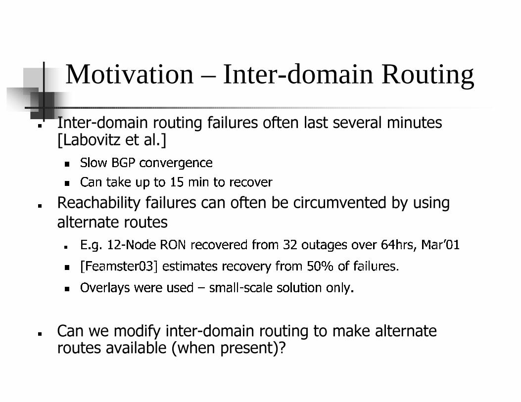
� Inter-d o m a i n ro u ti ng f a i l u res o f ten l a s t s ev era l m i nu tes [L a b o v i tz et a l . ]
� � ��� � � � � �� � � �
� ��� � �� � � � �� �� � � � �� � � � �
� R ea c h a b i l i ty f a i l u res c a n o f ten b e c i rc u m v ented b y u s i ng a l terna te ro u tes
� ��� � � !#" $&% '�( ) * $�+ ( ,% -( + ( '. + % / 0 ! % 1 243 �( 5 % -( + 67 8+ 5:9 ; 3 + <=
> ?@ ( 3 / 5 2( + = 0 A ( 5 2 B / 3 2( 5+ ( ,% -( + C. + % / D = E % . . 3 B F 1+ ( 5�
> * -( + F 3 C 5G ( + ( 1 5( 'IH 5 / 3 F F " 5 , 3 F�( 5% F 1 2 B% J % J F C�
K Can we modify inter-domain routing to make alternate routes av ailab le ( w h en p res ent) ?

Motivation – Intra-domain Routing
� Typically link weights (OSPF) set to achieve desired u tiliz ations (f or known traf f ic m atrix )
� C an Perf orm ance b e a prob lem ?
� � ��� � � � � � � �� � � � � � � ��� � � � � � � ��� � � � � ��� � � � � � � � � � � � � ��� � � �
� � � � � � � � � � � � ! �� � ��" � �� � � �# $�% & � ')( � � � ��* � � � � +-,
. Cannot adapt to changes in traffic load
/ 0( � � � � � � � � � � � � � � � � � �� � � �� � � " � � �� � � � � � �
. I f su ch ov er-pov isioning is not affordab le: can w e au tom atically adapt to significant changes in the load?

Part 1- Inter-domain Routing
� Goal – i m p r ov e i n t e r -d om ai n r e ac h ab i li t y b y u s i n g e x i s t i n g r e d u n d an c y i n t h e A S g r ap h .
� N e t w or k -lay e r ap p r oac h -
� ��� �� � � � � � � � � �� � � � � � � � � � � � � � � �� � � � � � � � � ��
�� � � � � �
� Evolutionary/Overlay approach (last retreat)
� � � �� �� � � � � � � � � � �� � � � � � � � � � � � � � � � � ! �� � � � � � � � � �� � � �
� � � � � � �� �#"
Path Vector Background
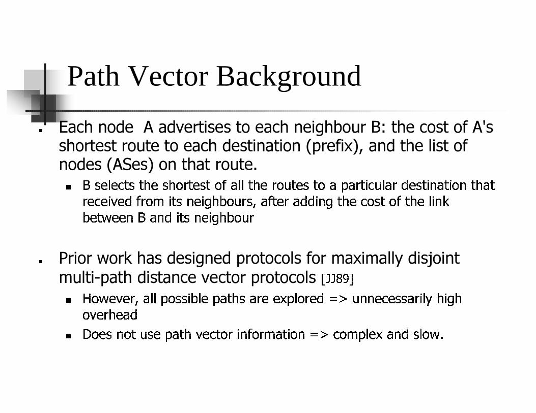
� Each node A advertises to each neighbour B: the cost of A's shortest route to each destination ( p refix ) , and the l ist of nodes ( AS es) on that route.
� � �� � � � � � � � � � � � �� � � � � � � � � � � �� � � � � � � � � � � � � � � ��� � � � � � �
�� �� ��� � � � � � � � � � � ��� �� � � ��� � �� � � � � � � � � � � � � � � � � � ��� �
� � ��� � � � � � � � � � � � ��� � � � �
� P rior w ork has designed p rotocol s for m ax im al l y disj oint m ul ti-p ath distance vector p rotocol s �� � ! "
# $�% & '( ')+* , - -. % / / 0 1 - '. , 2 3 / , ) ' '4 . -% ) ' 5 6 78 9 9 ': ' / / , ) 0 -<; 3 0�= 3
% ( ' ) 3 ' , 5
# >% ' / 9 % 28 / '. , 2 3 ( ': 2% ) 0 9 ?% ) @ , 2 0% 9 6 7 : % @. - ' 4 , 9 5 / -% &+A

Our Network Layer Approach
� Extend B G P ' s p a th v ec to r p r o to c o l to a dv er ti s e k ( ~ 2 ) r o u tes p er des ti na ti o n i ns tea d o f 1 .
� ��� � ��� � � � � � � � � ��� �� � � � � � � � � �
� First of the k routes is computed using the current BGP route-sel ection.
� T he rema ining k-1 routes a re sel ected to b e ma x ima l l y l ink-disj oint ( a t the A S -l ev el ) .
� � � � � �� � ��� ��� � � � �� � � � � � � � �
� � � � � �� � ��� � � � � � � � �� �� � � � � � � � � �� ��� � � � �� � � � � � � !� � �
� � � � �� � �� � � � � � � �� � � � � � � � � � � � � � �
� " � � � � � � � � � � �� �� � $# �� � �� � � � .

Service Model
� How will the use of the alternate routes be triggered?
� Network node can automatically switch when the default route chang es;
� � � � � � � � � � �� � � � � � � � � �� � � �� � � � � � ��� �
� � � � � � � � �� � � � � � � � � � �
� � � � � � � � � � � � � �� � !" #
$ Best way to validate a routing entry is to send and receive p ack ets via th at route
% & � � � � � � � � � � � � � � � �(' � � � � � � � � � � � � � � �)� �� � � � � �* �
� � � � � � � � + � � � � �
% , -�. /0 1 10 2 3 4. -5 67 - 6 68(9 . : 6 4 ; . 2< 0 =

Results
� Construct AS-l e v e l top ol og i e s a nd d e f a ul t p a th s f rom B G PR oute v i e w s d a ta .
� � �� � �� �� � � � � �� � � � � � �
� � �� � � � � � �� � � � � ���
� � � � � � � �� � � � � � � � ���
� Construct routi ng ta b l e s usi ng k-p a th v e ctor.
� Find r e a c h a b il it y / f a il u r e p r o b a b il it y o f a l l de s t ina t io ns f o r a g iv e n no de ( u nde r r a ndo m s ing l e l ink f a il u r e )
� Just using k=2 greatly improves reachability
1 2 3 4 5
0
0.1
0.2
0.3
0.4
0.5
0.6
0.7
0.8
0.9
1
Fa ilure Probabilities
K (Ad.s per de s tina tion)
Nor
ma
lize
d F
ailu
re P
rob
abili
ty
Part 2 – Intra-domain Routing
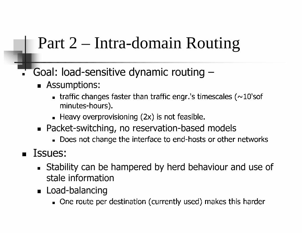
� Goal: load-s e n s i t i v e dy n am i c r ou t i n g –
� Assumptions:
� ��� � � �� �� � � � � � � � � � � � � � � �� � � ��� � � � � � � � � � ��� � � � �� �
� � � � � ��� � � � � ��
� � � ! � � " � � � � � � � � � � �# $ � � � � � � � � � � % �& �
' Packet-s w i tch i n g , n o r es er v ati o n -b as ed m o d el s
� ( � � � � � � � � � & � � � � � � �� � ) � � � � � � � � � & � � ��* � � + �
, Issues:
- Stability can be hampered by herd behaviour and use of stale information
. L oad-balancing
/ 021 34 56 7 38 34 9 3: 7 ; 1 < 7 ; 51 =&> 6 4 4 31 7 ?A@ 6 : 3 9B C < D 3: 7 E ; : E <4 9 34

Background
� Typical intra-d o m ain pro to co l: link -s tate , e . g . O S P F
� ��� � � �� � �� � � �� � � � � � � �� �� � �� � � � � �� � � � � � ��� � � � � � � � �
� � � � � � � � � � �
� � � � � � � ��� � � � ��� �! "# � � � � � $ � � � �� � � � ��� � � � � � � � �
� % � � � � �� � � � � � � � � � � � �� � �� � �
& Using a load-b ase d m e t r ic ( lik e de lay ) dir e c t ly c an b e u nst ab le '( � � � )*,+ - �� � �� * * .
/ 01 2�3 4 4 3 56 7 89 : 8 :; <; 3 = < >9 ?A@ > 2�3 > 9 <; < = BC <; D <C 3 EGF B3 ; < D 3 > C :H
I > ? C ?GJ 3 > ? : 4 3 4 D @ 3 83 @ ? > E B3 ; < D 3 > 2 ?AK 2 I > ? C ?GJ 3 > ? : 4!L
M N > ? C C @ 3 4 ; < < :; @ ? C C 3 > ? : 4 ;!O D : <; 4 P > B3 C 3 4 @ < C :3 DQ 9 <C 3 > < D H :9 R�S
0 T3 4 K 6U 7V L
M W < >H :9 RXY ?3 = < > <9 F D < 8 < 4 D < 4 > = < >9 ? @ F ; < > > ? 4 K

Points of Attack
� Granularity of Routing Unit
� Currently one route per destination
� Route S e le c tion M e th od
� Currently least-c ost f irst ( “g reedy”)
� Routing M e tric
� Currently static m etric s ref lec ting h op-c ount or w eig h ts pre-determ ined b y traf f ic eng ineers.
Our approach – Route granularity
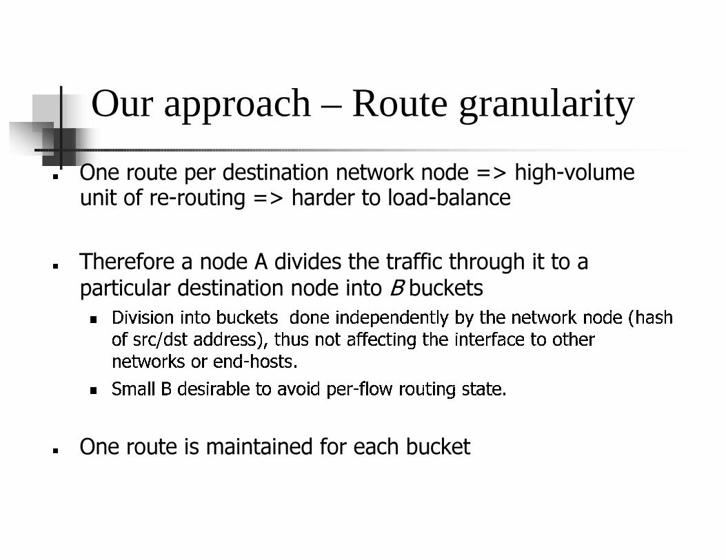
� One route per destination network node => high-v ol um e unit of re-routing => harder to l oad-b al anc e
� T heref ore a node A div ides the traf f ic through it to a partic ul ar destination node into B b uc kets
� �� ���� � �� � � � �� ��� � � �� � � � � � � � � � � � ��� � � � � � � �� � � � � � � ��� � �
� � � � � �� � � � � � � � ��� � � � � � � � �� � � � � � � � � � �� � � � � � �
� � � �� �� �� � � �! � �� � "
# $&% � � � ' � � � � � � � � � � � �� � � � � � � � � � �� � � � � � � "
( One route is maintained for each bucket
Our Approach – Randomization
� Assume the link state (metric) is the load in the last link state p eriod.
� L ink state is inherently stale
� � ���� �� �� � � � �� � � � � �� � ��� � � � � � � � � � �� �� � � ��� � � � � � � � � �
� We introduce randomness into the routes selected across dif f erent b uck ets f or the same destination
� �� � � � � � � � �� � �� � � � � �� � � � � �� �
� � �� � � � � � � � � � � � �� �� � � � � � � ! � � � � �� � � � � � � �� �� � � �� �� "
� #$ � ��% � � � � � �� &' ( � � �) � � � � � * � �� �,+ � �+ - � � � � � � � � � �� � . ) � �
� � � � � � � � � � � � � � � � � �� � � � + � � � � �� � ) � � � � �� � � � � � �
/ C an also randomize t ime of rou t e-c h ang e ac ros s b u c k et s
0 E dg e-b as ed rou t e-s el ec t ion, t o av oid rou t ing inc ons is t enc y .

Our Approach – Metric
� Separation of static and dynamic metrics
� Capacity (or propagation delay) can be adv ertiz edinf req u ently
� L oad (or q u eu e-length ) need m ore f req u ent adv ertis em ent
� L oad metric can b e fu rth er improv ed ( fu tu re w ork )
� B y s im u lating th e s ys tem and bu ilding a m odel of load-trans ition.
� T h is im prov es perf orm ance f or bes t-f irs t s election, bu t not s ignif icantly f or random s election w ith “bu ck etiz ation”
Simulation Results
� Use random “f ork ”/ t -s t op ol og i es ( ~ 5 0 nodes)
� � � � ��� � � � � �� � � � � � � �� � � � � � � �� � �� �� � ��� � � � � � � � � � �� �� � � � �
� � � � � � �
Traffic matrix such that the o v erp ro v isio n in g facto r O . F . ( min [ C ap acity / L o ad ] ) is l o w ( ~ 1 . 2 )
O b j ectiv es
! � � " � � � � � � ��# � � � � � � � � � $ �� � �� � � � � � � � � � � � � � $ � � ��� � � � � � �� � �� �
� � � �� % $ � � �� � � $& � � � � � '
! (� " � � � �*) � � � � � � � � � �� � �� � � �� � � � � � � � � � � �+ � � � � � � � � $ � �) � � � �
$ � � "�
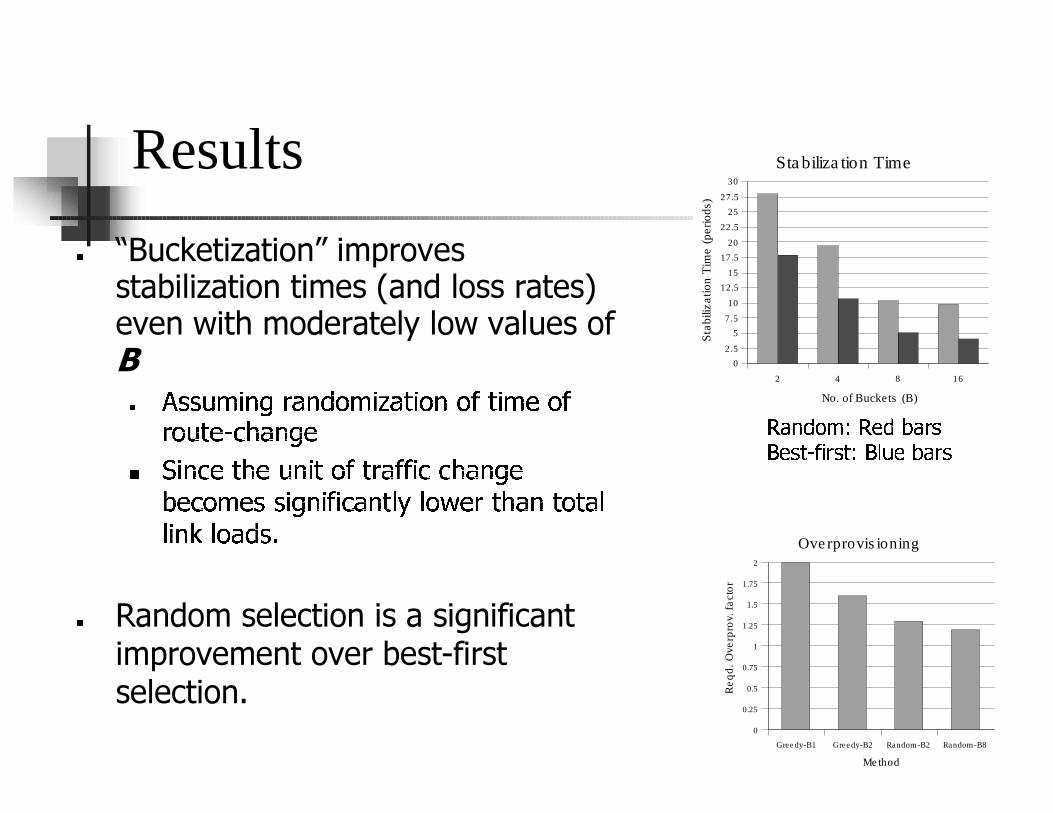
Results
� “B u c k e t i z a t i o n ” i m p r o v e s s t a b i l i z a t i o n t i m e s ( a n d l o s s r a t e s ) e v e n w i t h m o d e r a t e l y l o w v a l u e s o f B
� ��� � � � ��� � � �� � ��� � � � � � � � �� �
� �� � � � � � �
� ���� �� � � � �� � �! " �$# % " "� � � � %� & �
' � � ( � ) )� &� � "� � %� � *,+ * -� # � � %� � � % *
* ��� . * % / )10
2 Random selection is a significant imp r ov ement ov er b est-fir st selection.
2 4 8 16
0
2.5
5
7.5
10
12.5
15
17.5
20
22.5
25
27.5
30
Sta biliza tion Time
No. of Buckets (B)
Sta
biliz
atio
n T
ime
(per
iods
)
Gree dy-B1 Gree dy-B2 Random-B2 Random-B8
0
0.25
0.5
0.75
1
1.25
1.5
1.75
2
Ove rprovis ioning
Me thod
Re
qd
. O
verp
rov.
fa
cto
r
3546 7$8 9: 35; 7< 4= >
? ; > @BA CD= > @: ? E�F ; < 4= >

Conclusion and Future Work
� In Conclusion..
� ��� � � �� � � � � � � � �� � � � � � � �� � � � � � � � � �� ��� � � � � �� � � � � � � � �
� � � � � � � � � � � � � � � � � � � ��� � � � � �
� ��� � � � � � � � � � � � � � � � � � � � � � � � � � � � � � � � � � �� � � � � � � � � �
�� � � � � � � � � �� � � � � � � � � �! �� � � �� � � �� �� � � � � � � � � � �
� � � � � � � � � �� � � �#"
$ Future Work:
% Better, Dynamic Evaluation Scenario
& ')( * +�, - . +0/ 1 ( 2 */ 3 4 2 *)5 . 6 ( 2( 7/ - * 3 2 . -�8 60/ 5 ( * 3 -/ , 2 * 39
: ; -( 7 7 * 1 5 ( 2 - *�< ( 3 6 2/ =/ +/ 9 > 7/ - * 3 2 -( 8 6/ 5 ( * 3 -/ , 2 * 39
? Better metric for load-s en s itiv e rou tin g
: @)A . 5 / 6 . + / 7 A 2( 2 . 1 B ( 3 9 .#C
: D 7 7 . 1 2 / 7 7 * + 2 . - * 39#E * 3 1/ - =/ -( 2 . 6 . + ( > * 3 7/ C


