OATA Preliminary System Safety Assessment (En-Route) Document Identifier: OATA-P2-D9.2-04 Edition: 0.21 Edition Date: 19-04-2007 EUROPEAN ORGANISATION FOR THE SAFETY OF AIR NAVIGATION OVERALL ATM/CNS TARGET ARCHITECTURE E U R O C O N T R O L
Transcript
OATA Preliminary System Safety Assessment (En-Route)
This document presents a Preliminary System Safety Assessment (PSSA) of OATA-compliant systems in the en-route phase of Air Traffic Management. It is part of a safety assessment of the OATA project, and will contribute to the OATA Preliminary Safety Case. The PSSA includes a detailed analysis of the causes of the functional hazards identified in the Functional Hazard Assessment conducted earlier in the project. It defines a set of safety requirements, intended to ensure that OATA-compliant systems will enable ATM to comply with its overall safety targets.
Keywords
OATA Safety assessment PSSA TLS
Contact Person(s) Tel Unit Prepared by: Guy Cozon, John Spouge, DNV +44 207716 6592
Issued by: +32 2 729 XXXX SD/ESC
STATUS, AUDIENCE AND ACCESSIBILITY Status Intended for Accessible via
In progress General Public Intranet Internal Draft EATM Stakeholders Extranet Working Draft Restricted Audience Configuration Manager Proposed Issue
Released Issue Printed & electronic copies of the document can be obtained from the EATM Infocentre or from the OATA PSO
OATA Preliminary System Safety Assessment (En-Route)
OATA-P2-D9.2-04 , Edition: 0.21 Page: 6 of 45
Overall ATM/CNS Target Architecture
EXECUTIVE SUMMARY This document presents a Preliminary System Safety Assessment (PSSA) of OATA-compliant systems in the en-route phase of Air Traffic Management (ATM). It is part of a safety assessment of the OATA project, and will contribute to the OATA Preliminary Safety Case (PSC). The PSSA consists of a detailed analysis of the causes of the hazards identified in the Functional Hazard Assessment (FHA) conducted earlier in the project.
The objectives of the PSSA can be summarised as follows:
• Identify and quantify the causes of hazards identified in the FHA.
• Allocate quantitative safety requirements, where possible, to OATA elements (i.e. modules or packages of modules).
The PSSA has categorised the causes of the hazards from the FHA as:
• System failures, i.e. failures of an OATA element.
• Human errors by the system operator, which may be influenced by the performance of the technical system.
• Interdependencies between system elements and between the human and system.
Failures of the OATA elements have been systematically identified through developing a functional model and applying a Failure Mode and Effects Analysis (FMEA), which is complementary to the hazard identification workshop based on OATA Use Cases. The effects of these failures have been quantified through fault tree and influence models using an extended version of the Integrated Risk Picture (IRP).
From this model, the PSSA has defined a set of safety requirements, intended to ensure that OATA-compliant systems for the en-route phase of flight will enable ATM to comply with its overall safety targets. The following types of safety requirements have been specified for the OATA elements:
• Integrity requirements - these specify the maximum permitted failure rate for OATA elements whose failure may be a distinct causal factor of accidents.
• Quality of service requirements - these specify the minimum beneficial influence that the OATA elements must have on the human contribution to the safety functions.
• Interdependency requirements - these specify the maximum permitted interdependencies involving OATA elements.
• Coverage requirements - these specify the minimum extent of implementation of the OATA elements.
The values presented in Section 4 of this report represent initial suggestions for what safety requirements should be. After validation or further model development, the requirements can be adjusted, and compensating adjustments made to other requirements, representing alternative and more practical ways of meeting the overall safety targets.
OATA Preliminary System Safety Assessment (En-Route)
OATA-P2-D9.2-04 , Edition: 0.21 Page: 7 of 45
Overall ATM/CNS Target Architecture
1 INTRODUCTION
1.1 Background In the Overall ATM/CNS Target Architecture (OATA) project, EUROCONTROL is developing a target architecture for future Air Traffic Management (ATM) and Communications, Navigation and Surveillance (CNS) systems. OATA is a high-level design for future ATM systems of European States, representing an integrated ATM “system of systems”, towards which the current collection of national systems will evolve. This is intended to improve integration and interoperability, and facilitate the introduction of Operational Improvements.
The OATA project requires a Preliminary Safety Case (PSC), in order to demonstrate the top level claim that OATA is acceptably safe in principle for implementation by ECAC States. This work, which includes development of the underlying safety assessment, is carried out by Det Norske Veritas (DNV), teamed with Ebeni Limited. The first stages of the safety assessment were a Functional Hazard Assessment (FHA) [Ref 1] and Safety Assessment Workshop [Ref 7]. This document presents the Preliminary System Safety Assessment (PSSA), which develops a more detailed analysis of the hazards identified in the FHA and workshop.
1.2 Objective and Scope The objectives of the PSSA can be summarised as follows:
• Identify and quantify the causes of hazards identified in the FHA.
• Allocate quantitative safety requirements, where possible, to OATA elements (i.e. modules or packages of modules).
The scope of the study is defined in the FHA [1].
1.3 Approach The FHA describes the overall methodology for the safety assessment, based on the use of the Integrated Risk Picture (IRP) [Ref 5]. The FHA includes a functional model in sufficient detail to support the PSSA. It identifies a small set of functional hazards suitable to separate the modelling causes and consequences, and presents event tree models of their consequences. It also develops an OATA-specific risk model, and demonstrates that this is compliant with the ESARR4 safety target. This OATA-specific risk model is the basis of the PSSA.
The following steps have been used to conduct the PSSA according to the defined approach:
• Identification of the contribution of OATA elements to causing the functional hazards. This uses a failure modes and effects analysis, and is presented in Section 2.
• Development of a full causal model for the functional hazards, covering human errors as well as system failures. This uses an OATA-specific development of the IRP. It is presented in Section 3.
• Specification of safety requirements for the OATA elements. These are obtained by using the IRP to apportion the safety objectives into the different causal factors. The results are given in Section 4.
OATA Preliminary System Safety Assessment (En-Route)
OATA-P2-D9.2-04 , Edition: 0.21 Page: 8 of 45
Overall ATM/CNS Target Architecture
2 HAZARD IDENTIFICATION
2.1 Functional Hazards The FHA report identified the following functional hazards for the en-route phase:
• Ineffective synchronisation (MB9) - the planning controller provides a synchronisation plan that does not eliminate conflicts, thus requiring tactical intervention to maintain separation standards.
• Ineffective tactical separation - the executive controller fails to maintain separation standards, thus requiring separation recovery or collision avoidance. This includes ineffective separation in the scenarios of plannable conflicts (MB5), unplannable conflicts (MB6) and ATCO-induced conflicts (MB7).
• Ineffective STCA warning (MB3) - STCA fails to prompt mitigation of the separation infringement.
The identification codes (MB9 etc) are those used in the IRP for these hazards. IRP codes are also used below indicate causal factors (e.g. MB9.2.1 is one of the modelled causes of MB9).
The term “ineffective” in the functional hazards covers all causes of events with the stated consequences. This includes not only controller errors and system failures, but also cases where the failure is due to non-fitment of necessary equipment (e.g. STCA), and where the failure is due to pilot response. In principle, it also includes cases where normal fault-free operation is not sufficient to prevent the conflict developing to the next stage.
The reasons for the choice of these hazards are explained in the FHA report [Ref 1]. The FHA modelled their consequences and apportioned safety objectives to them. The aim of the PSSA hazard identification is therefore to identify their causes and relate them to the OATA architecture.
2.2 Causal Analysis The causes of the functional hazards could be categorised in many different ways, but for simplicity in relating them to the OATA architecture, it is appropriate to make the following high-level breakdown:
• System failures, in which the functional hazard is mainly caused by a failure of the technical system (e.g. software fault). Such a failure may be mitigated by actors (e.g. through reversion to manual separation), but the primary cause of any resulting accident would be the technical failure. These failures represent the most obvious contribution of OATA to the functional hazards.
• Human errors, in which the functional hazard is mainly caused by an error by a human operator (e.g. a lapse by an executive controller). This error may have subsidiary causes such as poor quality of the technical system, which are represented in IRP as influences on the likelihood of the error. These influences represent the contribution of OATA to the human causes of functional hazards.
These type of causes are not entirely distinct, and possible interdependencies are considered in Section 2.4 below. Nevertheless, they usefully separate the OATA contribution from the human causes.
OATA Preliminary System Safety Assessment (En-Route)
OATA-P2-D9.2-04 , Edition: 0.21 Page: 9 of 45
Overall ATM/CNS Target Architecture
The causes of system failures can also be categorised in different ways, but for simplicity in relating them to the OATA architecture, it is appropriate to treat each OATA element that is represented in the functional model as a potential cause of system failure. The following section therefore considers possible failures of each element of the OATA en-route architecture in turn. In order to model their consequences, it is necessary to link them to the IRP structure, which is achieved by considering their effects on the ATC safety functions.
2.3 System Failure Analysis This section conducts a Failure Modes & Effects Analysis (FMEA) of the OATA en-route architecture, in order to identify systematically the possible contributions of OATA elements to causing functional failures. The FMEA results are shown in full in Table 2.1. The process is as follows.
Each element of OATA for the en-route phase of flight (defined in the functional model in the FHA) has been considered in turn. The function of the module has been defined from available OATA documentation [Ref 3]. Possible failure modes have been identified using a checklist [based on Ref 8]:
• Total failure to operate (complete loss of data)
• Misleading information, including: o Partial loss of data o Data corruption o Misdirection o Delay o Out of sequence o Inconsistency
The effects of each failure on the ATC safety functions are then based on the defined function of the OATA element, combined with judgement about potential controller response and fall-back options. In future work, these judgements could be improved through the use of expert workshops. Failure modes with similar effects have been grouped together. Relatively unlikely or insignificant failure modes have been omitted for clarity. Any knock-on effects need to be considered only to the point where they can be related to the IRP structure, since subsequent effects are modelled probabilistically through IRP. Table 2.1 includes cross-references to the events that are modelled in IRP in Section 3.
The analysis assumes that the OATA system is completely deployed and well established, and hence it excludes problems due to the introduction process and integration issues. It considers each OATA module as if they were independent, and interdependencies between OATA elements and between the system and the human operator are addressed in Section 2.4. Other qualitative safety concerns have been included as comments in Table 2.1.
OATA Preliminary System Safety Assessment (En-Route)
OATA-P2-D9.2-04 , Edition: 0.21 Page: 10 of 45
Overall ATM/CNS Target Architecture
Table 2.1 OATA Module FMEA Air Surveillance The Air Surveillance cluster is responsible for surveillance of airborne targets. It includes interfaces to surveillance sensors, maintenance of air tracks, multi-sensor tracking and distribution of system tracks in accordance with surveillance data requests from users. Failure Modes Effects IRP X-ref Comments Erroneous Data
Could be caused by data sensor processing. Not necessarily obvious to the ATCO. Could cause invalid instructions to be supplied by the ATCO. Could lead to failure of Correlation and Profile Prediction, as well as Safety Nets.
New event MB10.1.3
Data corruption/ Failure to Operate (Partial)
As above As above
Failure to Operate (Total)
Would be obvious to ATCO. Possible use of primary radar picture or VHF reports. Increased workload.
Influence on Traffic Synchronisation, Tactical Separation and Separation Recovery
Correlation It has the responsibility of logically associating surveillance data represented by a System Track with a Flight. This association is called Correlation. The creation and deletion of the correlations in the system is responsibility of this module. Failure Modes Effects IRP X-ref Comments Erroneous Operation
Some tracks wrongly identified. This would not be obvious to the ATCO. Could cause instructions to be supplied to an incorrect aircraft. It will also affect profile Prediction.
New event MB10.2.4
Failure to Operate (Partial, only some flights are unidentified)
Unidentified flight(s) will have to be manually identified by the ATCO. Moderate workload increase.
Influence on Traffic Synchronisation and Tactical Separation
Failure to Operate (Total)
No tracks are identified. This degradation would be obvious to the ATCO. Manual correlation would be required, causing very large ATCO workload increase.
Influence on Traffic Synchronisation and Tactical Separation
Emergency procedure required
Table continued on next page.....
OATA Preliminary System Safety Assessment (En-Route)
OATA-P2-D9.2-04 , Edition: 0.21 Page: 11 of 45
Overall ATM/CNS Target Architecture
Flight Data Management The Flight Data Management module has the responsibility of managing flight parameters and data. Its main purpose is holding the information of all the flights in the system, and for each one assuring that there is a consistency between all its parts, especially in case a service related to a certain flight or to a set of flights is accomplished by the participation of other modules. This is done by sequencing calls to the operations offered by other modules' interfaces in a way that assures that the flight is always in a consistent state after the service has finished executing. The “What if” contexts and “What If” Flights are also managed by this module, but this is outside the current safety assessment scope. As a consequence, this module’s interface represents the main entry point to access or update flight data. Failure Modes Effects IRP X-ref Comments Erroneous Data
Could be caused by erroneous input. Not necessarily obvious to the ATCO. Could cause invalid instructions to be supplied by the ATCO. Could lead to failure of Profile Prediction.
New event MB10.2.2
Data corruption/ Failure to Operate (Partial)
Not necessarily obvious to the ATCO. Particularly a problem if ATC and aircraft have different data. Could cause spurious deviation alerts or aircraft to deviate.
Influence on Traffic Synchronisation, Tactical Separation and Communications
Failure to Operate (Total)
Would be obvious to ATCO. Increased workload. Influence on Traffic Synchronisation, Tactical Separation and Communications
Flight Path Monitoring It monitors the tracks related to correlated flights in the system in order to follow the progress along the flight profile and detect deviations from the predicted trajectory. To do so, a set of internal thresholds is used. It will distribute deviations when one is detected. It will distribute as well conformance information to inform the users about the progression of flights that are conform. It can, in certain situations, decide to invoke the Flight Data Management module in order to recompute the trajectory to adequate it to the current situation. The trajectory will be updated when the overfly of a trajectory point is detected, marking it as overflown. It has also the responsibility of detecting when the airborne status of a flight has changed, that is, when it has taken off or landed. Failure Modes Effects IRP X-ref Comments Failure to Operate (Partial)
Controller may not be aware of failure, deviation may not be detected
New Event MB6.1.2.3.2.2.3
Failure to Operate (Total)
If controller is aware system is not working, workload will be increased
Influence on Tactical Separation
Spurious Warnings Repeated could cause ignorance of genuine level bust Influence on Tactical Separation
Table continued on next page.....
OATA Preliminary System Safety Assessment (En-Route)
OATA-P2-D9.2-04 , Edition: 0.21 Page: 12 of 45
Overall ATM/CNS Target Architecture
Inter Sector Coordination And Transfer The Coordination and Transfer Package is responsible for notification, coordination and transfer between sectors belonging to the same ATC units or to adjacent units (ACC, APP and TWR) ; civil and military sectors; or ACC and oceanic sectors. Moreover, this module provides support to civil-military crossing and to oceanic clearance management. Notification of the flight takes place before coordination, in order to ensure, whenever possible, that the receiving unit contains a filed flight plan corresponding to the flight. The receiving unit is also notified in case of significant changes affecting coordination. Coordination and transfer are performed automatically for flights adhering to predefined, standard coordination conditions (Letter of Agreement). Non standard conditions require the controller intervention, to be either accepted, counter proposed or rejected. Hand over from the transferring unit to the receiving one involves two aspects: transfer of control and transfer of the voice communications. Failure Modes Effects IRP X-ref Comments Data Corruption Could cause flight to be transferred at a point not
expected by the other sector. The aircraft will then be at a position other than expected based on the flight data the new sector receives. This could create a conflict in the new sector. However, once detected by the radar system of the new sector the flight data will be updated accordingly or the system will raise a deviation alert.
Influence on Traffic synchronisation, Tactical Separation and Communications. New events MB9.5.1 and MB5.1.4.1.
Failure to Operate This would be obvious and would cause an increase to the controller’s workload
Influence on Traffic synchronisation, Tactical Separation and Communications.
Table continued on next page.....
OATA Preliminary System Safety Assessment (En-Route)
OATA-P2-D9.2-04 , Edition: 0.21 Page: 13 of 45
Overall ATM/CNS Target Architecture
Medium Term Conflict Detection The Medium Term Conflict Management is responsible for : detection of medium-term conflicts between flights by analysing flight information (trajectory); notification of the detected conflicts to the concerned controllers provision on request of advisories to solve the detected conflicts. The time period to be regarded as the 'Medium Term' will depend on local working practice, however, widely accepted values are between 5 - 20 minutes. The conflicts are predicted within the ATSU Area of Interest. The purpose of the function is to minimise the number of interventions performed by the Executive Controller. Failure Modes Effects IRP X-ref Comments Failure to Operate Increased workload to Executive Controller Influence on Traffic
Synchronisation and Tactical Separation
This has been covered in the workshop, Use Case No.99
Identifies conflict on wrong aircraft
Worse than FTO: could hide genuine conflict. Planning Controller failure to recognise conflict
New Event MB9.4.1.2.2
Spurious Operation Repeated could cause ignorance of genuine conflict. Influence on Traffic Synchronisation and Tactical Separation
Profile Prediction The Profile Prediction module is responsible calculating the profile of a flight. It updates the flight plan with the current aircraft track. Failure Modes Effects IRP X-ref Comments Inaccurate profile
Not necessarily obvious to the ATCO. This has a major impact on MTCD and synchronisation planning.
New event MB10.3.1
Failure to Operate (Partial/Total)
Would be obvious to ATCO. Need to fall back on flight plan data. Increased workload.
Influence on Traffic Synchronisation and Tactical Separation
Table continued on next page.....
OATA Preliminary System Safety Assessment (En-Route)
OATA-P2-D9.2-04 , Edition: 0.21 Page: 14 of 45
Overall ATM/CNS Target Architecture
Reminder Management The Reminder Management module has the responsibility to implement those functions needed to remind the controller of planned flight related actions. Where appropriate, the relevant reminders will be issued a short parameter time before or after the predicted occurrence of the associated event. Failure Modes Effects IRP X-ref Comments Fails to Operate If controller reliant upon reminders, could cause reduced
performance New events MB9.6.1 and MB5.1.2.3.2.3
Spurious Operation Repeated could cause ignorance of genuine reminders or ATCO to switch off system
Influence on Traffic Synchronisation and Tactical Separation
Safety Nets Based on air surveillance information, it detects:
- imminent (< 2 min) violation of prescribed separation minima between aircraft in flight (STCA); or - imminent violation of minimum safe altitude/height by aircraft in flight (MSAW); or - imminent violation of active airspace restrictions by aircraft (APW).
The detection should have a time horizon of at least 1 minute more than the corresponding function in the air. The decision to publish or not a certain conflict depends in some cases (e.g. vertical separation and RVSM) on the characteristics of the flight possibly correlated to the analysed tracks. Failure Modes Effects IRP X-ref Comments Failure to Operate No warning in impending collision Existing event MB3.2 Identifies conflict on wrong aircraft
Worse than FTO: distraction could hide more conflict As above
Spurious Operation Repeated could cause ignorance of genuine conflict Influence on Separation Recovery
Sequence Planning This module determines optimised sequences planning, providing the corresponding flight advisories in order to realise the sequences. Failure Modes Effects IRP X-ref Comments Failure to Operate Increased planning controller workload. Influence on Traffic
Synchronisation
Data Corruption May lead planning controller to introduce conflicts. Likely to be detected by MTCD
New event MB9.3.1
Table continued on next page.....
OATA Preliminary System Safety Assessment (En-Route)
OATA-P2-D9.2-04 , Edition: 0.21 Page: 15 of 45
Overall ATM/CNS Target Architecture
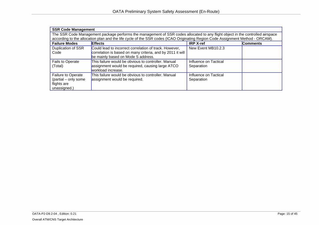
SSR Code Management The SSR Code Management package performs the management of SSR codes allocated to any flight object in the controlled airspace according to the allocation plan and the life cycle of the SSR codes (ICAO Originating Region Code Assignment Method - ORCAM). Failure Modes Effects IRP X-ref Comments Duplication of SSR Code
Could lead to incorrect correlation of track. However, correlation is based on many criteria, and by 2011 it will be mainly based on Mode S address.
New Event MB10.2.3
Fails to Operate (Total)
This failure would be obvious to controller. Manual assignment would be required, causing large ATCO workload increase.
Influence on Tactical Separation
Failure to Operate (partial – only some flights are unassigned.)
This failure would be obvious to controller. Manual assignment would be required.
Influence on Tactical Separation
OATA Preliminary System Safety Assessment (En-Route)
OATA-P2-D9.2-04 , Edition: 0.21 Page: 16 of 45
Overall ATM/CNS Target Architecture
2.4 Interdependencies
2.4.1 Types of Interdependencies The failure modes above are described as if they were independent, but in reality some causal factors (e.g. failures of some parts of the system) may also affect other apparently separate causal factors. This type of interdependency may have an important effect on the accident risk. It is therefore desirable to identify these interdependencies at an early stage, so that they can be managed.
In the IRP, interdependencies of this type are identified and modelled. They are represented in three major groups:
• Common-cause failures, affecting different causal factors at once. For example, power failure might affect the whole of the ATM system, causing multiple barrier failure, i.e. simultaneous occurrence of the different functional hazards.
• Negative interactions, where safety gains in one area are accompanied by losses in another. In the case of OATA, the most important is the possibility that improved system performance and automation might undermine traditional controller skills and vigilance, which may offset the expected safety benefits.
• Positive interactions, where safety gains in one area result in improvements in another. In the case of OATA, improved system design might allow a better quality of human-machine interface, which might improve overall controller performance.
One further type of interdependency is particularly important for OATA; namely interoperability. This is discussed further in Section 4.6.2.
2.4.2 Common Causes The barrier model presented in the FHA is the best starting point for identifying critical common causes. Common cause failures of separate barriers such as Traffic Synchronisation, Tactical Separation and Separation Recovery strongly affect the overall system reliability. It would be desirable for a workshop to identify common causes of failure of these functions and recommend ways of increasing the independence of these barriers.
The functional model provides a framework for identification of common causes at a more detailed level. It represents common causes as inputs that are supplied to more than one functional element. In the en-route ATC functional model [1], the main common causes of failure are:
• Traffic information, particularly the surveillance picture from the Air Surveillance module, which is used by Traffic Synchronisation, Tactical Separation and Separation Recovery.
• ATC Environment, which provides constraint information to all three functions. The effects of failure of this package have been considered in Table 2.1 above.
• ATC system, which consists of the common elements underlying both elements. These include power supply, centralised data storage, air conditioning system, display consoles etc. These are not modules within OATA, but their failure could cause failure of all of the elements considered in Table 2.1.
Relevant requirements are specified in Section 4.4.
OATA Preliminary System Safety Assessment (En-Route)
OATA-P2-D9.2-04 , Edition: 0.21 Page: 17 of 45
Overall ATM/CNS Target Architecture
2.4.3 Negative Interactions Negative interactions may be experienced anywhere that improved performance is attempted. This is consistent with a theory of risk homeostasis, in which safety improvements result in a change in human behaviour that tends to counteract their effect, leading to relatively constant risk levels.
In the case of OATA, the most important such interaction is the possibility that improved system performance and automation might undermine traditional controller skills, which may reduce their understanding of the system and their ability of intervene in the case of system problems. Controllers supplied with more sophisticated ATM systems and may feel that their individual vigilance is less important, offsetting the expected improvement in safety performance. Although this is represented in IRP, it is not really subject suitable for quantification. It is, however, a possibility that should be actively guarded against through the careful design of the human-system interface, and operator training.
2.5 Relationship to Workshop The FMEA above is complementary to the workshop of OATA use cases that has been conducted already [Ref 7]. In future work, it could be carried out in an extended workshop.
The workshop covered three use cases; Resolve Ad Hoc Conflict, Modify the Planned Sequence and Coordinate Flight Transfer Conditions & Perform Transfer of Responsibility for Control of a Flight. The output of the first use case, Resolve Ad Hoc Conflict, has been used to develop the FMEA for the Medium Term Conflict module, as this is the system component involved in this use case. The output of the Modify the Planned Sequence use case discussion has been used in the FMEA for the Sequence Planning module.
OATA Preliminary System Safety Assessment (En-Route)
OATA-P2-D9.2-04 , Edition: 0.21 Page: 18 of 45
Overall ATM/CNS Target Architecture
3 IRP MODEL
3.1 General Approach The IRP represents the causes of the functional hazards in a fault tree model. The fault tree is fully quantified for a base case referring to current (2005) performance and a future (2020) OATA-specific case, which is also compliant with the ESARR4 safety target (as developed in the FHA). The latter forms the basis for apportionment of the safety target into safety objectives and OATA module requirements.
For the present study, the IRP fault trees have been extended to show failures of the OATA elements as identified in the FMEA above. In some cases, failures of the OATA elements are not sufficiently distinct to represent in fault trees, so these are represented in the influence model instead. These fault trees and influence models are presented in Figures 3.1 to 3.10 below. The models refer to the future (2020) case. The top event probabilities are consistent with the hazard frequencies shown in the FHA.
The fault trees also show the “contribution” of each event to the overall frequency of mid-air collisions. The contribution is a simple estimate of the maximum reduction in accident frequency that would occur if the causal factor was eliminated and other factors remained constant [Ref 5].
Underneath the base events in the fault trees are shown the tasks that are considered to be in progress when the events occur. These form the links to the influence model. The tasks “traffic synchronisation”, “traffic separation” and “separation recovery” are those shown in the functional model [Ref 1]. Base events that are failures of OATA elements are potentially influenced by the quality of the ATM system as a whole, and these are labelled “ATM system” so this is shown at this point.
3.2 Traffic Synchronisation Ineffective traffic synchronisation (MB9) is defined as failure to provide and communicate a plan for a synchronised traffic flow, thus requiring tactical intervention to maintain collision separation standards.
Possible causes of ineffective traffic synchronisation are shown in the fault tree in Figure 3.1 to 3.2. They are structured as follows:
• No traffic synchronisation (MB9.1). This failure mode is necessary to allow the model to represent current situations where no distinct synchronisation planning is undertaken.
• Inadequate traffic information for synchronisation (MB9.2). This is where the planning controller or system do not receive the necessary information to plan a synchronised traffic flow. It may be caused by inadequate correlated traffic picture (in the case of manual synchronisation) or inadequate correlated tracks (in the case of system support). Both cases are represented by MB10.2 below.
• Inadequate traffic sequencing (MB9.3). This is where sequencing is the cause of failure to mitigate a pre-tactical conflict. If it created a conflict, a different model structure would be required. If there was no attempt at traffic sequencing (i.e. a first-come, first-served principle), this type of error would not arise. It includes:
o Sequence Planning system failure (MB9.3.1). This is where misleading system support for sequencing causes the failure to mitigate a pre-tactical conflict. Complete system failure, where sequence planning is prevented, would not cause this.
OATA Preliminary System Safety Assessment (En-Route)
OATA-P2-D9.2-04 , Edition: 0.21 Page: 19 of 45
Overall ATM/CNS Target Architecture
o Planning controller misjudgement of sequencing (MB9.3.2). This is where misjudgement by the planning controller causes the failure to mitigate a pre-tactical conflict.
• Inadequate medium-term conflict planning (MB9.4). This includes:
o Failure to identify medium-term conflict (MB9.4.1). This is where the planning controller or MTCD does not identify a conflict despite having the necessary information. Its causes are a combination of:
Planning controller failure of strip-based conflict identification (MB9.4.1.1). This refers to failure to identify conflicts by inspection of the control strips, in the absence of MTCD.
Ineffective Medium-Term Conflict Detection (MB9.4.1.2). This refers to the MTCD implementation for planning. It may be due to:
- No MTCD coverage (MB9.4.1.2.1).
- MTCD (planning) system failure (MB9.4.1.2.2). This is where MTCD does not identify a conflict despite having the necessary correlated tracks.
- Planning controller failure to respond to MTCD alert (MB9.4.1.2.3). This is considered to be a common-cause with MB9.4.1.1.
o Planning controller misjudgement of conflict resolution (MB9.4.2).
• Inadequate inter-sector coordination (MB9.5). This includes failures of multi-sector planning and co-ordination between different planning controllers. It includes:
o Inter-Sector Coordination system failure (MB9.5.1). This is where misleading system support causes a co-ordination failure. Complete system failure may be a cause of this. In reality, the probability of this event may be limited to that of failure of the back-up telephone connection, but this is neglected for simplicity.
o Planning controller inadequate coordination (MB9.5.2). This is where misunderstanding between the planning controller and controllers in other sectors leaves a conflict embedded in the sector transfer conditions. Although errors may occur on either part, the planning controller is considered responsible for the communication.
• Inadequate coordination with executive controller (MB9.6). This covers failures of intra-sector co-ordination between planning and executive controllers through the synchronisation plan.
o Reminder Management system failure (MB9.6.1).
o Planning controller failure to alert executive controller to conflict (MB9.6.2). This is where misunderstanding between the planning controller and executive controller in the same sector leaves a conflict embedded in the tactical situation. Although errors may occur on either part, the planning controller is considered responsible for the communication.
Introduction of MTCD as a new barrier against the scenario MB9.4.1.1 introduces the potential for common causes (CCF9), which are primarily due to poor planning controller
OATA Preliminary System Safety Assessment (En-Route)
OATA-P2-D9.2-04 , Edition: 0.21 Page: 20 of 45
Overall ATM/CNS Target Architecture
performance. For simplicity, these are represented by MB9.4.1.2.3. The modelling of common causes is explained in the IRP report [Ref 5].
OATA Preliminary System Safety Assessment (En-Route)
OATA-P2-D9.2-04 , Edition: 0.21 Page: 21 of 45
Overall ATM/CNS Target Architecture
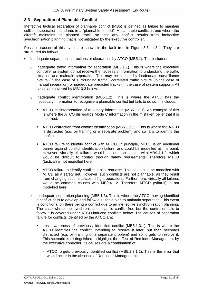
3.3 Separation of Plannable Conflict Ineffective tactical separation of plannable conflict (MB5) is defined as failure to maintain collision separation standards in a “plannable conflict”. A plannable conflict is one where the aircraft maintains its planned track, so that any conflict results from ineffective synchronisation planning that is not mitigated by the executive controller.
Possible causes of this event are shown in the fault tree in Figure 3.3 to 3.4. They are structured as follows:
• Inadequate separation instructions or clearances by ATCO (MB5.1). This includes:
o Inadequate traffic information for separation (MB5.1.1). This is where the executive controller or system do not receive the necessary information to understand the traffic situation and maintain separation. This may be caused by inadequate surveillance picture (in the case of surrounding traffic), correlated traffic picture (in the case of manual separation) or inadequate predicted tracks (in the case of system support). All cases are covered by MB10.3 below.
o Inadequate conflict identification (MB5.1.2). This is where the ATCO has the necessary information to recognise a plannable conflict but fails to do so. It includes:
ATCO misinterpretation of trajectory information (MB5.1.2.1). An example of this is where the ATCO disregards Mode C information in the mistaken belief that it is incorrect.
ATCO distraction from conflict identification (MB5.1.2.2). This is where the ATCO is distracted (e.g. by training or a separate problem) and so fails to identify the conflict.
ATCO failure to identify conflict with MTCD. In principle, MTCD is an additional barrier against conflict identification failure, and could be modelled at this point. However, virtually all failures would be common causes with MB9.4.1.2, which would be difficult to control through safety requirements. Therefore MTCD (tactical) is not modelled here.
ATCO failure to identify conflict in pilot requests. This could also be modelled with MTCD as a safety net. However, such conflicts are not plannable, as they result from changing circumstances in flight operations. Furthermore, virtually all failures would be common causes with MB9.4.1.2. Therefore MTCD (what-if) is not modelled here.
o Inadequate separation planning (MB5.1.3). This is where the ATCO, having identified a conflict, fails to develop and follow a suitable plan to maintain separation. This event is conditional on there being a conflict due to an ineffective synchronisation planning. The case where the synchronisation plan is conflict-free but the controller fails to follow it is covered under ATCO-induced conflicts below. The causes of separation failure for conflicts identified by the ATCO are:
Lost awareness of previously identified conflict (MB5.1.3.1). This is where the ATCO identifies the conflict, intending to resolve it later, but then becomes distracted (e.g. by training or a separate problem) and so forgets to resolve it. This scenario is distinguished to highlight the effect of Reminder Management by the executive controller. Its causes are a combination of:
- ATCO forgets previously identified conflict (MB5.1.3.1.1). This is the error that would occur in the absence of Reminder Management.
OATA Preliminary System Safety Assessment (En-Route)
OATA-P2-D9.2-04 , Edition: 0.21 Page: 22 of 45
Overall ATM/CNS Target Architecture
- Ineffective Reminder Management (MB5.1.3.1.2). It is assumed that the ATCO can use the Reminder Management module as a safeguard against the above error. This may be ineffective due to:
> No Reminder Management coverage (MB5.1.3.1.2.1). This failure mode is necessary to allow the model to represent the current situation where Reminder Management is not available.
> ATCO inadequate use of Reminder Management (MB5.1.3.1.2.2). This is considered to be a common cause with MB5.1.3.2.1.
> Reminder Management system failure (MB5.1.3.1.2.3).
> ATCO failure to respond to Reminder Management (MB5.1.3.1.2.4).
ATCO misjudgement in separation (MB5.1.3.2). This is where the ATCO misjudges the necessary action to prevent the loss of separation, e.g. misjudging flight profiles.
o Inadequate ATCO co-ordination (MB5.1.4). This is where the ATCO identifies the conflict and develops an appropriate plan to maintain separation, but fails to implement it due to problems in co-ordinating with other ATCOs. This may be due to:
Inter-Sector Transfer system failure (MB5.1.4.1). This is where misleading system support causes a co-ordination failure. Complete system failure, forcing telephone coordination, may be a cause of this.
ATCO inter-sector coordination error (MB5.1.4.2). This is where misunderstanding between the executive controllers in different sectors prevents planned mitigation of a conflict. Strictly, this should refer to conflicts that are allowed to remain, and conflicts that are created should be included in ATCO-induced conflicts below.
Reminder Management system failure. This is also a possible cause but is considered negligible and so is omitted for simplicity.
• Inadequate communication of clearance/instructions to pilot (MB5.2). This may be due to:
o Inadequate ATCO transmission, e.g. incorrect clearance (due to slips, similar callsigns etc), late clearance (due to workload), unclear phraseology etc.
o Loss of communication. This may be due to:
Error in frequency change, e.g. ATCO error in transmitting frequency change, pilot readback error, pilot error in setting new frequency.
VHF interference.
Sleeping VHF receiver.
VHF equipment malfunction.
o Inadequate pilot readback. This may consist of:
Pilot failure to readback, combined with ATCO failure to insist on readback.
OATA Preliminary System Safety Assessment (En-Route)
OATA-P2-D9.2-04 , Edition: 0.21 Page: 23 of 45
Overall ATM/CNS Target Architecture
Pilot error in readback (including readback by wrong aircraft), combined with ATCO hearback error or failure to challenge incorrect readback.
• Inadequate pilot response (MB5.3).
Introduction of Reminder Management as a new barrier against the scenario MB5.1.3.2 introduces the potential for common causes (CCF10), which are primarily due to poor ATCO performance. For simplicity, these are represented by MB5.1.2.3.2.2.
Figure 3.3 Fault Tree of Separation of Plannable Conflict
MB5 Ineffective separation of
plannable conflict9.8E-03
per plannable conflict
Contribution 0.1548
MB5.1 Inadequate separation instructions
MB5.2 Inadequate communication of instructions to pilot
MB5.3 Inadequate pilot response to ATC
5.2E-03 3.0E-03 1.5E-03per plannable conflict per plannable conflict per plannable conflict
4.5E-04 9.0E-04 1.1E-03 1.7E-03 4.3E-05 7.8E-04per plannable conflict per plannable conflict per plannable conflict per plannable conflict per plannable conflict per plannable conflict
Traffic separation Direct input Traffic separation ATC system (tactical) Traffic separation
E5
AND
OR
OATA Preliminary System Safety Assessment (En-Route)
OATA-P2-D9.2-04 , Edition: 0.21 Page: 24 of 45
Overall ATM/CNS Target Architecture
3.4 Separation of Unplannable Conflict Ineffective tactical separation of unplannable conflict (MB6) is defined as failure to maintain collision separation standards in an “unplannable conflict”, i.e. one that results from pilot deviations from the instructed trajectory or by military or VFR traffic in controlled airspace. In future work, it may be desirable to model conflicts from unidentified targets (e.g. VFR traffic) separately, since there is no legal requirement on the controller to maintain separation from these.
Possible causes of this event shown in the fault tree in Figure 3.5 to 3.6. They are structured as follows:
• Inadequate separation instructions by ATCO (MB6.1). This includes:
o Inadequate traffic information for separation (MB6.1.1). This is where the executive controller or system do not receive the necessary information to identify an unplannable conflict. This may be caused by inadequate surveillance picture (in the case of surrounding traffic), correlated traffic picture (in the case of manual monitoring) or inadequate predicted tracks (in the case of system support). All cases are covered by MB10.3 below.
o ATCO failure to identify the conflict in time (MB6.1.2). This is where the ATCO has the necessary information to recognise an unplannable conflict but fails to do so. The following scenarios have been identified from AIRPROX reports:
ATCO failure to identify conflict from military traffic (MB6.1.2.1). An example of this is where traffic in a nearby military training area penetrate an airway without authorisation. The ATCO might be distracted, or the conflict may develop too rapidly to detect using their normal monitoring.
ATCO failure to identify conflict from VFR traffic (MB6.1.2.2). An example of this is where VFR traffic penetrate an airway without authorisation. The ATCO might be distracted, or the traffic might not be subject to monitoring.
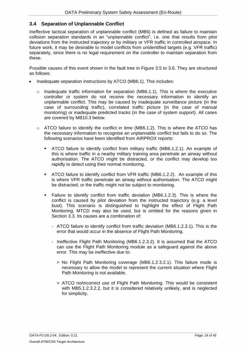
Failure to identify conflict from traffic deviation (MB6.1.2.3). This is where the conflict is caused by pilot deviation from the instructed trajectory (e.g. a level bust). This scenario is distinguished to highlight the effect of Flight Path Monitoring. MTCD may also be used, but is omitted for the reasons given in Section 3.3. Its causes are a combination of:
- ATCO failure to identify conflict from traffic deviation (MB6.1.2.3.1). This is the error that would occur in the absence of Flight Path Monitoring.
- Ineffective Flight Path Monitoring (MB6.1.2.3.2). It is assumed that the ATCO can use the Flight Path Monitoring module as a safeguard against the above error. This may be ineffective due to:
> No Flight Path Monitoring coverage (MB6.1.2.3.2.1). This failure mode is necessary to allow the model to represent the current situation where Flight Path Monitoring is not available.
> ATCO no/incorrect use of Flight Path Monitoring. This would be consistent with MB5.1.2.3.2.2, but it is considered relatively unlikely, and is neglected for simplicity.
OATA Preliminary System Safety Assessment (En-Route)
OATA-P2-D9.2-04 , Edition: 0.21 Page: 25 of 45
Overall ATM/CNS Target Architecture
> Flight Path Monitoring failure to give deviation alert (MB6.1.2.3.2.2). This is where FPM does not identify a deviation despite having the necessary predicted tracks.
> ATCO failure to respond to deviation alert from Flight Path Monitoring (MB6.1.2.3.2.3). This is considered to be a common cause with MB6.1.2.3.1.
o ATCO misjudgement in separation. This would be consistent with MB5.1.3.1, but it is difficult to distinguish from MB6.1.2 given the rapid conflict development, and is neglected for simplicity.
o Inadequate ATCO co-ordination. This would be consistent with MB5.1.4, but it is considered relatively unlikely given the rapid conflict development, and is neglected for simplicity.
• Inadequate communication of instructions to pilot (MB6.2).
• Inadequate pilot response (MB6.3).
Introduction of Flight Path Monitoring as a new barrier against the scenario MB6.1.2.3 introduces the potential for common causes (CCF11), which are primarily due to poor ATCO performance. For simplicity, these are represented by MB6.1.2.3.2.3.
Figure 3.5 Fault Tree of Separation of Unplannable Conflict
MB6 Ineffective separation of
unplannable conflict1.1E-01
per unplannable conflict
Contribution 0.5195
MB6.1 Inadequate separation instructions
MB6.2 Inadequate communication of instructions to pilot
Traffic separation Direct input ATC system (tactical) Traffic separation
F3
AND
OR
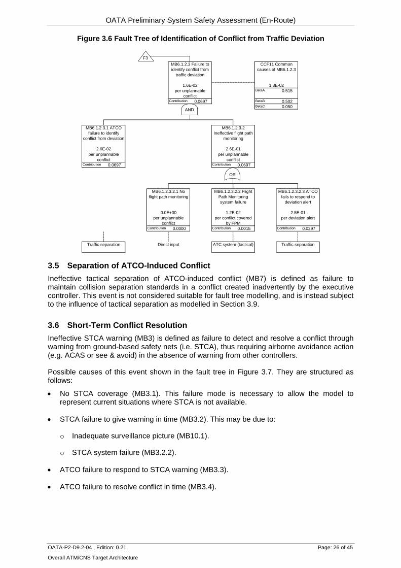
3.5 Separation of ATCO-Induced Conflict Ineffective tactical separation of ATCO-induced conflict (MB7) is defined as failure to maintain collision separation standards in a conflict created inadvertently by the executive controller. This event is not considered suitable for fault tree modelling, and is instead subject to the influence of tactical separation as modelled in Section 3.9.
3.6 Short-Term Conflict Resolution Ineffective STCA warning (MB3) is defined as failure to detect and resolve a conflict through warning from ground-based safety nets (i.e. STCA), thus requiring airborne avoidance action (e.g. ACAS or see & avoid) in the absence of warning from other controllers.
Possible causes of this event shown in the fault tree in Figure 3.7. They are structured as follows:
• No STCA coverage (MB3.1). This failure mode is necessary to allow the model to represent current situations where STCA is not available.
• STCA failure to give warning in time (MB3.2). This may be due to:
o Inadequate surveillance picture (MB10.1).
o STCA system failure (MB3.2.2).
• ATCO failure to respond to STCA warning (MB3.3).
• ATCO failure to resolve conflict in time (MB3.4).
OATA Preliminary System Safety Assessment (En-Route)
OATA-P2-D9.2-04 , Edition: 0.21 Page: 27 of 45
Overall ATM/CNS Target Architecture
Figure 3.7 Fault Tree of Short-Term Conflict Resolution
MB3 Ineffective STCA warning
3.4E-01per sep infringement
Contribution 1.0000
MB3.1 No STCA coverage
MB3.2 STCA fails to give warning in time
MB3.3 ATCO fails to respond to STCA
warning
MB3.4 ATCO fails to recover separation in
time
0.0E+00 5.1E-02 2.2E-01 1.2E-01per sep infringement per separation inf with
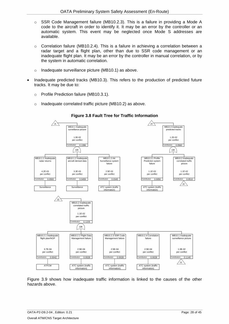
3.7 Traffic Information Inadequate traffic information (MB10) is defined as failure to provide information sufficient to enable traffic synchronisation, tactical separation and separation recovery. Although slightly different information is required for each task, they are grouped here for simplicity.
Possible causes of this event are shown in the fault tree in Figure 3.8. They are structured as follows:
• Inadequate surveillance picture (MB10.1). This refers to the production of targets prior to identification. Inadequacy may be due to:
o Inadequate radar returns (MB10.1.1). This is the targets from the primary or secondary radar. Faults may be due to the radar hardware.
o Inadequate aircraft derived data (ADD) (MB10.1.2). This is the transponded information from the aircraft (Mode C, Mode S or ADS). Faults may be due to the aircraft transponder or the information derived from the flight crew or aircraft systems. These are not separately modelled at present.
o Air Surveillance system failure (MB10.1.3). This is the system that combines and distributes the radar returns and ADD.
• Inadequate correlated traffic picture (MB10.2). This refers to the production of identified targets and their correlated tracks based on flight plans. Inadequacy may be due to:
o Inadequate NOP/flight plan (MB10.2.1). This is an inadequacy in the approved flight plan or the consolidated network operations plan.
o Flight Data Management failure (MB10.2.2). This is a inadequacy in the distribution and presentation of the flight plan to the ATCOs. It may be an error by the controller (or assistant) in displaying the flight strips or a fault in an electronic system.
OATA Preliminary System Safety Assessment (En-Route)
OATA-P2-D9.2-04 , Edition: 0.21 Page: 28 of 45
Overall ATM/CNS Target Architecture
o SSR Code Management failure (MB10.2.3). This is a failure in providing a Mode A code to the aircraft in order to identify it. It may be an error by the controller or an automatic system. This event may be neglected once Mode S addresses are available.
o Correlation failure (MB10.2.4). This is a failure in achieving a correlation between a radar target and a flight plan, other than due to SSR code management or an inadequate flight plan. It may be an error by the controller in manual correlation, or by the system in automatic correlation.
o Inadequate surveillance picture (MB10.1) as above.
• Inadequate predicted tracks (MB10.3). This refers to the production of predicted future tracks. It may be due to:
o Profile Prediction failure (MB10.3.1).
o Inadequate correlated traffic picture (MB10.2) as above.
Figure 3.8 Fault Tree for Traffic Information
MB10.1 Inadequate surveillance picture
MB10.3 Inadequate predicted tracks
1.0E-02 1.2E-02per conflict per conflict
Contribution 0.1396 Contribution 0.0560
MB10.1.1 Inadequate radar returns
MB10.1.2 Inadequate aircraft derived data
MB10.1.3 Air Surveillance system
failure
MB10.3.1 Profile Prediction system
failure
MB10.2 Inadequate correlated traffic
picture
4.2E-03 3.3E-03 2.5E-03 1.1E-03 1.1E-02per conflict per conflict per conflict per conflict per conflict
3.8 Influence Models Many causal factors are not suitable for modelling using fault trees, and in the IRP these are instead represented as influences on the base events in the fault trees. The influences are are categorised as influences from the actors, equipment, task inputs and constraints, for consistency with the SADT models in Ref 1.
The influence models for Traffic Synchronisation, Tactical Separation and Conflict Resolution have been extended to highlight the OATA elements that affect the ATC system, and are shown in Figure 3.10 to 3.12.
In the influence models, performance scores (PS) in excess of 70 indicate performance better than current ECAC average. These are based on assumptions given in the IRP report [Ref 5] and refer to the future (2020) target-compliant case. They are converted to modification factors (MF), such that MF<1 where PS>70. Their effects are limited to a maximum (ME), based on the contribution of each influence in actual experience of failures in these tasks [Ref 5]. The negative interactions described in Section 2.4.3 are represented by correlations between the system and actor performance, giving correlated modification factors (CMF) that partly offset the benefits of system improvements. The values for the correlation factors are based on EUROCONTROL domain expert judgements [Ref 5]. The base event probabilities in the fault tree for the current (2005) case are multiplied by the MFs (or CMFs for actors) to give the base event probabilities for the future (2020) target-compliant case, which are shown in Figures 3.1 to 3.9.
Figure 3.10 Influence Model for Traffic Synchronisation
Traffic synchronisation
Score 81.0Max effect 98%
MF 0.33
ACTOR EQUIP'T INPUTS CONST'SPlanning controller ATC system Total inputs Airspace design
Score 77.1 Score 84 Score 81.5 Score 70Max effect 90% Correlation Max effect 50% Max effect 53% Max effect 13%
MF 0.58 -0.20 MF 0.72 MF 0.75 MF 1.00CMF 0.61
Fundamental Score Max effect Element Input Score Max effectResources 77 45% MTCD NOP/4D flight plan 80 38%Competence 77 30% Sequence planning Traffic picture 84 25%HMI 77 6% Coordination & transferReliability 77 48%Procedures 77 3%Teamwork 77 45%
OATA Preliminary System Safety Assessment (En-Route)
OATA-P2-D9.2-04 , Edition: 0.21 Page: 30 of 45
Overall ATM/CNS Target Architecture
Figure 3.11 Influence Model for Tactical Separation
Tactical separation
Score 77.0Max effect 98%
MF 0.50
ACTOR EQUIP'T INPUTS CONST'SExecutive controller ATC system Total inputs Airspace design
Score 72.0 Score 84 Score 80.2 Score 70Max effect 91% Correlation Max effect 28% Max effect 71% Max effect 3%
MF 0.85 -0.20 MF 0.86 MF 0.66 MF 1.00CMF 0.88
Fundamental Score Max effect Element Input Score Max effectResources 70 46% Flight path monitoring NOP/4D flight plan 80 6%Competence 77 36% MTCD Traffic picture 84 38%HMI 77 7% Reminder management ATC coordination 77 13%Reliability 65 46% Coordination & transfer Aircraft sequence 81 30%Procedures 77 3% Info from pilot 72 19%Teamwork 77 43%
Figure 3.12 Influence Model for Separation Recovery
TASKATC conflict resolutionScore 74.7
Max effect 57%MF 0.87
ACTOR EQUIP'T CONST'SExecutive controller ATC system Airspace design
Score 72.0 Score 84 Score 70.0Max effect 22% Correlation Max effect 22% Max effect 30%
MF 0.98 -0.20 MF 0.89 MF 1.00CMF 1.01
ElementSTCA
At present, there is no model to show the effects of individual OATA elements on the overall ATM system quality, so these are not quantified individually within the influence model (although they are quantified individually in the fault trees). Overall performance scores of the ATM systems for Traffic Synchronisation, Tactical Separation and Separation Recovery are assumed to be 84, based on the requirements to meet the ESARR4 safety target developed in the FHA [1]. A PS of 84 for the ATM system corresponds to a 75% reduction in system failures, and also a 50% reduction in task errors that it has the potential to affect (based on the relationship assumed in the IRP), whereas a PS of 70 corresponds to no change in the current error probability. In future work, it will be desirable to verify the practicability of this requirement.
3.9 Sources of Values in Fault Trees Table 3.1 provides a summary of the sources of the values in the fault trees in Figures 3.1 to 3.9. It also lists the probabilities for the 2005 baseline case, and the 2020 target-compliant case. For base events in the fault tree, the ratio of these two probabilities is the modification factor from the influence models in Figure 3.10 to 3.12.
Some of the parameters are based on previous statistical studies or actual AIRPROX data, documented in the original IRP models [Ref 9]. Table 3.1 provides cross-references to the Appendices in this report where the sources are more fully described. Where a probability is based on no occurrences in a known dataset, the assumed equivalent number is given in quotes (e.g. “0.3”).
OATA Preliminary System Safety Assessment (En-Route)
OATA-P2-D9.2-04 , Edition: 0.21 Page: 31 of 45
Overall ATM/CNS Target Architecture
Other parameters are based on assumptions made in the original IRP study or especially for the present study. In general, assumptions are made where no suitable data or alternative methods are available.
Some parameters are estimated by bottom-up combination of values for lower events, using the fault tree logic. Others are based on consistency with values above or on either side in the fault tree, using top-down fault tree logic. These approaches are explained in the IRP report [Ref 9].
3.10 Uncertainties The fault trees above are an extension of the fault trees in the IRP, and are therefore subject to the uncertainties discussed in Ref 5. They involve extensive judgements about the way future ATM changes might affect the causal factors, most of which have not yet been confirmed by topic specialists, and for which robust judgements are not practical until the concept of operations is more stable. They are based on a target-compliant case whose realism has not yet been validated. In showing the contribution of OATA elements, they make use of extensive assumptions due to a lack of detailed data or hazard identification workshops on ATM system failures.
However, the IRP provides the best currently available picture of the ATM contribution to aviation accident risks. Being based on accident and incident experience, it is a more realistic prediction than can be obtained from expert judgement. It therefore provides the best available prediction of the likely contribution of OATA elements. It is therefore the most suitable basis for allocating safety requirements to them.
Furthermore, it may be noted that although the individual causal factors in the model (and hence each individual safety requirement below) are extremely uncertain, the combined model of the effects of all causal factors is much more robust. This is because the IRP has been developed using a top-down approach from actual accident and incident experience, and has been shown to be consistent with their historical trends. Hence, while any individual causal factor (or safety requirement) might vary substantially (for example, if better data or judgements were obtained), other causal factors will in most cases be required to vary in the opposite direction, so that the overall risks remain the same. This makes the risk model very appropriate for adjustment of safety requirements, as discussed in Section 4.5 below.
OATA Preliminary System Safety Assessment (En-Route)
OATA-P2-D9.2-04 , Edition: 0.21 Page: 32 of 45
Overall ATM/CNS Target Architecture
Table 3.1 Sources of Fault Tree Values PARAMETER 2020
PROB 2005
PROB 2020/2005
RATIO SOURCE OF 2005 VALUE
Traffic information MB10.1 Inadequate surveillance picture 1.0E-02 4.0E-02 0.250 As MB3.2.1 MB10.1.1 Inadequate radar returns 4.2E-03 1.7E-02 0.247 Consistency MB10.1.2 Inadequate aircraft derived data 3.3E-03 1.3E-02 0.247 4 of 12 traffic picture influences on UK AIRPROXs 2003 MB10.1.3 Air Surveillance system failure 2.5E-03 1.0E-02 0.247 3 of 12 traffic picture influences on UK AIRPROXs 2003 MB10.2 Inadequate correlated traffic picture 1.1E-02 4.4E-02 0.253 Consistency MB10.2.1 Inadequate flight plan/NOP 3.7E-04 1.0E-03 0.368 Assumed 2.5% of MB10.1 MB10.2.2 Flight Data Management failure 2.5E-04 1.0E-03 0.247 Assumed 2.5% of MB10.1 MB10.2.3 SSR Code Management failure 2.5E-04 1.0E-03 0.247 Assumed 2.5% of MB10.1 MB10.2.4 Correlation failure 2.5E-04 1.0E-03 0.247 Assumed 2.5% of MB10.1 MB10.3 Inadequate predicted tracks 1.2E-02 4.8E-02 0.253 Bottom-up MB10.3.1 Profile Prediction system failure 1.1E-03 4.4E-03 0.247 Assumed 10% of MB10.2 Traffic synchronisation MB11 Ineffective ATFCM 2.5E-01 5.0E-01 0.500 Assumption (App III.5.13.1) MB9 Ineffective traffic synchronisation 3.2E-03 2.3E-02 0.137 Consistency MB9.1 No traffic synchronisation 0.0E+00 9.7E-03 0.000 Consistency MB9.2 Inadequate traffic information for synchronisation 1.5E-03 5.8E-03 0.253 3 of 12 ECAC AIRPROXs 2001-3 MB9.3 Inadequate traffic sequencing 6.3E-05 1.9E-04 0.324 "0.1" of 12 ECAC AIRPROXs 2001-3 MB9.3.1 Sequence Planning system failure 4.8E-06 1.9E-05 0.247 Assumed 10% of MB9.3 MB9.3.2 Planning controller misjudgement of sequencing 5.8E-05 1.7E-04 0.333 Consistency MB9.4 Inadequate medium-term conflict planning 4.0E-04 3.9E-03 0.102 2 of 12 ECAC AIRPROXs 2001-3 MB9.4.1 Failure to identify medium-term conflict 2.0E-04 3.3E-03 0.061 Consistency MB9.4.1.1 PC failure of strip-based conflict identification 1.2E-03 3.5E-03 0.333 Consistency MB9.4.1.2 Ineffective medium-term conflict detection 8.1E-02 9.3E-01 0.087 Bottom-up MB9.4.1.2.1 No MTCD coverage 0.0E+00 9.0E-01 0.000 Assumption MB9.4.1.2.2 MTCD system failure 4.9E-02 2.0E-01 0.247 Assumption MB9.4.1.2.3 Planning controller fails to respond to MTCD 3.3E-02 1.0E-01 0.333 Assumption MB9.4.2 Planning controller misjudgement of resolution 1.9E-04 5.8E-04 0.333 "0.1" of 12 ECAC AIRPROXs 2001-3 MB9.5 Inadequate inter-sector coordination 6.3E-04 1.9E-03 0.324 1 of 12 ECAC AIRPROXs 2001-3 MB9.5.1 Inter-Sector Coordination system failure 4.8E-05 1.9E-04 0.247 Assumed 10% of MB9.5 MB9.5.2 Planning controller coordination error 5.8E-04 1.7E-03 0.333 Consistency
OATA Preliminary System Safety Assessment (En-Route)
OATA-P2-D9.2-04 , Edition: 0.21 Page: 33 of 45
Overall ATM/CNS Target Architecture
PARAMETER 2020 PROB
2005 PROB
2020/2005 RATIO
SOURCE OF 2005 VALUE
MB9.6 Inadequate coordination with executive controller 6.3E-04 1.9E-03 0.324 1 of 12 ECAC AIRPROXs 2001-3 MB9.6.1 Reminder Management system failure 4.8E-05 1.9E-04 0.247 Assumed 10% of MB9.6 MB6.2 Planning controller failure to alert executive controller to conflict
5.8E-04 1.7E-03 0.333 Consistency
Separation of plannable conflicts MB5 Ineffective separation of plannable conflict 9.8E-03 2.0E-02 0.489 Extrapolation of ATC simulations (App III.5.7.2) MB5.1 Inadequate separation instructions 5.2E-03 1.2E-02 0.430 Consistency MB5.1.1 Inadequate traffic information for separation 2.0E-04 7.9E-04 0.253 6 of 92 UK AIRPROXs 1995-97 (App III.5.7.8) MB5.1.2 Inadequate conflict identification 1.4E-03 2.7E-03 0.498 Consistency MB5.1.2.1 ATCO misinterpretation of trajectory information 4.5E-04 9.1E-04 0.498 1 of 3 UK/MUAC AIRPROXs 2001-3 MB5.1.2.2 ATCO distraction from conflict identification 9.0E-04 1.8E-03 0.498 Consistency MB5.1.3 Inadequate separation planning 2.8E-03 6.9E-03 0.412 4 of 7 UK/MUAC AIRPROXs 2001-3 MB5.1.3.1 Lost awareness of previously identified conflict 1.1E-03 3.5E-03 0.324 Consistency MB5.1.3.1.1 ATCO forgets previously identified conflict 1.8E-03 3.5E-03 0.498 Consistency MB5.1.3.1.2 Ineffective reminder management 2.9E-01 9.8E-01 0.293 Bottom-up MB5.1.3.1.2.1 No reminder management coverage 0.0E+00 9.5E-01 0.000 Assumption MB5.1.3.1.2.2 ATCO inadequate use of reminder 2.5E-01 5.0E-01 0.498 Assumption MB5.1.3.1.2.3 Reminder Management system failure 2.5E-04 1.0E-03 0.247 Assumption MB5.1.3.1.2.4 ATCO failure to respond to reminder 5.0E-02 1.0E-01 0.498 Assumption MB5.1.3.2 ATCO misjudgement in separation 1.7E-03 3.5E-03 0.498 2 of 4 UK/MUAC AIRPROXs 2001-3 MB5.1.4 Inadequate ATCO co-ordination 8.2E-04 1.7E-03 0.473 1 of 7 UK/MUAC AIRPROXs 2001-3 MB5.1.4.1 Inter Sector Transfer system failure 4.3E-05 1.7E-04 0.247 Assumed 10% of MB5.1.4 MB5.1.4.2 ATCO inter-sector coordination error 7.8E-04 1.6E-03 0.498 Consistency MB5.2 Inadequate communication of instructions to pilot 3.0E-03 6.0E-03 0.508 3 of 10 UK/MUAC AIRPROXs 2001-3 (App III.5.7.5) MB5.2.1 Inadequate ATCO transmission of instructions 8.6E-04 1.7E-03 0.508 Consistency MB5.2.2 Loss of communication 1.2E-03 2.3E-03 0.508 38% of comms failures in Europe 2002-3 (Tab III.5.7) MB5.2.3 Inadequate pilot readback 1.0E-03 2.0E-03 0.508 34% of comms failures in Europe 2002-3 (Tab III.5.7) MB5.3 Inadequate pilot response to ATC 1.5E-03 2.0E-03 0.770 "1" of 10 UK/MUAC AIRPROXs 2001-3 (App III.5.7.7) Separation of unplannable conflicts MB6 Ineffective separation of unplannable conflict 1.1E-01 2.3E-01 0.491 Consistency MB6.1 Inadequate separation instructions 6.7E-02 1.7E-01 0.392 Consistency MB6.1.1 Inadequate traffic information for separation 1.2E-02 4.8E-02 0.253 As MB10.3 MB6.1.2 ATCO failure to identify conflict in time 5.6E-02 1.3E-01 0.429 Consistency
OATA Preliminary System Safety Assessment (En-Route)
OATA-P2-D9.2-04 , Edition: 0.21 Page: 34 of 45
Overall ATM/CNS Target Architecture
PARAMETER 2020 PROB
2005 PROB
2020/2005 RATIO
SOURCE OF 2005 VALUE
MB6.1.2.1 ATCO failure to identify conflict from military traffic 3.0E-02 6.0E-02 0.498 6 of 13 UK/MUAC AIRPROXs 2001-3 MB6.1.2.2 ATCO failure to identify conflict from VFR traffic 1.0E-02 2.0E-02 0.498 2 of 13 UK/MUAC AIRPROXs 2001-3 MB6.1.2.3 Failure to identify conflict from traffic deviation 1.6E-02 5.0E-02 0.319 5 of 13 UK/MUAC AIRPROXs 2001-3 MB6.2 Inadequate communication of instructions to pilot 1.3E-02 2.6E-02 0.510 2 of 19 UK/MUAC AIRPROXs 2001-3 (App III.5.8.7) MB6.2.1 Inadequate ATCO transmission of instructions 3.8E-03 7.4E-03 0.508 Consistency MB6.2.2 Loss of communication 4.9E-03 9.7E-03 0.508 38% of comms failures in Europe 2002-3 (Tab III.5.7) MB6.2.3 Inadequate pilot readback 4.4E-03 8.7E-03 0.508 34% of comms failures in Europe 2002-3 (Tab III.5.7) MB6.3 Inadequate pilot response to ATC 3.8E-02 4.9E-02 0.770 4 of 19 UK/MUAC AIRPROXs 2001-3 (App III.5.8.8) STCA warning MB3 Ineffective STCA warning 3.4E-01 6.7E-01 0.517 Bottom-up MB3.1 No STCA coverage 0.0E+00 3.6E-01 0.000 EC judgement (App III.5.5.2) MB3.2 STCA fails to give warning in time 5.1E-02 2.0E-01 0.254 Judgement (App III.5.5.3) MB3.2.1 Inadequate traffic picture for STCA 1.0E-02 4.0E-02 0.250 1 of 5 UK AIRPROXs 1995-97 (Tab III.5.2) MB3.2.2 STCA system failure 4.1E-02 1.7E-01 0.247 Consistency MB3.3 ATCO fails to respond to STCA warning 2.2E-01 2.5E-01 0.874 3 UK/MUAC AIRPROXs 2001-3 cf 3 for MB3.2 (Tab
III.4.1) MB3.4 ATCO fails to recover separation in time 1.2E-01 1.3E-01 0.874 "0.7" UK/MUAC AIRPROXs 2001-3 cf 3 for MB3.2 (Tab
III.4.1)
OATA Preliminary System Safety Assessment (En-Route)
OATA-P2-D9.2-04 , Edition: 0.21 Page: 35 of 45
Overall ATM/CNS Target Architecture
4 SAFETY REQUIREMENTS
4.1 Types of Requirements The following types of safety requirements can be specified for OATA elements using the IRP:
A. Integrity requirements - these specify the maximum permitted failure rate for OATA elements whose failure may be a distinct causal factor of accidents. Strictly, this is the reliability, but it is commonly known as a safety integrity requirement.
B. Quality of service requirements - these specify the minimum beneficial influence that the OATA elements must have on the human contribution to the safety functions.
C. Interdependency requirements - these specify the maximum permitted interdependencies involving OATA elements.
D. Coverage requirements - these specify the minimum extent of implementation of the OATA elements.
Types A and B correspond to the two types of causal factors identified in Section 2.2. Type B and some type C can be seen as requirements on the quality of the human-machine interaction (HMI). Types B and D can also be considered “success case” requirements, discussed further in Section 4.5. All the requirements are expressed in the IRP model presented in Section 3. The following sections summarise the requirements from the model.
The requirements are intended to ensure that OATA-compliant systems, if fully implemented by 2020, would enable ATM to comply with its overall safety targets. Since OATA covers only the technical ATM system, not the human operators, it cannot ensure compliance with the targets. The requirements are therefore intended to ensure that OATA makes an appropriate contribution towards the overall targets. The IRP model makes assumptions about traffic growth, other changes in the operating environment, the performance of human operators in the ATM system and the performance of other ATM stakeholders. If all these assumptions are satisfied, and OATA satisfies the requirements above, and if the IRP modelling is all valid, then it can be expected that the ATM system as a whole will comply with its overall safety targets.
4.2 Integrity Requirements Integrity requirements for OATA elements are the probabilities of failure of each element shown in the fault trees for the target-compliant case. The safety requirements are expressed in Table 4.1 in two forms:
• Probabilities per demand, obtained directly from the fault trees.
• Frequencies per flight hour, obtained by multiplying the per-demand probabilities by the frequency of occurrence of the demands from the IRP target-compliant case.
Failures are defined as events sufficiently severe to cause the events above them in the fault trees in Section 3, which in most cases implies the failure of the traffic synchronisation, tactical separation or separation recovery functions defined in the functional model in the FHA. Example failure modes for each element are given in Table 2.1.
OATA Preliminary System Safety Assessment (En-Route)
MAXIMUM FAILURE PROBABILITY (per demand) IRP EVENT
Air Surveillance 2.1E-03 2.5E-03 per conflict MB10.1.3 Flight Data Management 2.1E-04 2.5E-04 per conflict MB10.2.2 SSR Code Management 2.1E-04 2.5E-04 per conflict MB10.2.3 Correlation 2.1E-04 2.5E-04 per conflict MB10.2.4 Profile Prediction 9.3E-04 1.1E-03 per conflict MB10.3.1 Sequence Planning 4.1E-06 4.8E-06 per synchronised conflict MB9.3.1 MTCD 4.3E-02 4.9E-02 per conflict covered by MTCD MB9.4.1.2.2Reminder Management 4.1E-05 4.8E-05 per pre-tactical conflict MB9.6.1 Inter Sector Coordination 4.1E-05 4.8E-05 per pre-tactical conflict MB9.5.1 Inter Sector Transfer 2.0E-07 4.3E-05 per plannable conflict MB5.1.4.1 Flight Path Monitoring 5.7E-05 1.2E-02 per conflict covered by FPM MB6.1.2.3.2STCA 1.4E-05 4.1E-02 per separation inf with STCA MB3.2.2
For system design purposes, different forms are meaningful for different systems:
• For MTCD and STCA, which are based on exposure to conflicts, a requirement per conflict is most appropriate.
• For Flight Path Monitoring, which is applied continuously during flights, a requirement per flight hour is most appropriate.
• For Correlation, SSR Code Management, Reminder Management and Inter Sector Coordination and Transfer, which are applied on discrete occasions to individual flights, it may be convenient to express these as failures per event using these systems. It is assumed that this occurs at an average of 2 events per flight hour in ECAC, giving a requirement per event 0.5x the tabulated value.
• For Flight Data Management, a requirement per system hour may be more appropriate. This is most simply obtained by multiplying by the tabulated frequency per flight-hour by average number of aircraft handled by the system at any one time.
To place the chosen requirements into context, they can be compared with the estimated current (2005) performance in the IRP baseline results. However, this is complicated because systems of the type defined by OATA are not necessarily installed at present. Therefore, such a comparison is only meaningful for probabilities per demand. The safety requirements in Table 4.1 are a factor of 4 lower than the 2005 performance, as a result of the assumptions made in developing the target-compliant case.
4.3 Quality of Service Requirements The integrity requirements above only address the OATA elements whose failure can be represented in a fault tree. The IRP model also takes account of the influence of the quality of performance of the OATA elements on human performance, which is an indirect effect on safety. The assumptions in the IRP model form a requirement on the human-machine interaction, and is known here as a quality of service requirement.
The performance score (PS) for all ATC systems is assumed to be 84 in developing the target-compliant case, as shown in the influence models in Section 3.8. This is equivalent to a 50% reduction in the ATCO task errors that they influence.
OATA Preliminary System Safety Assessment (En-Route)
OATA-P2-D9.2-04 , Edition: 0.21 Page: 37 of 45
Overall ATM/CNS Target Architecture
This excludes system failures that directly cause task failure, and includes only poor quality performance that influences an error that is primarily human. The errors include not only errors in identifying and separating conflicts, but also ATCO errors that might create conflicts, represented by functional hazard MB7 in Section 2.1, which is not suitable for more detailed modelling using fault trees.
The requirement is measured relative to a baseline of current (2005) performance. Since this requirement applies during a period in which commercial traffic is predicted to increase by a factor of 2.2, it is a demanding requirement.
4.4 Interdependency Requirements
4.4.1 Common Cause Requirements Common causes refer to a particular type of interdependency between OATA elements that may result in the failure of two or more barriers for a single (i.e. common) cause. Based on the functional model in Ref 1, the OATA elements that have this capability are shown in Table 4.2. These common causes are already accounted for in the IRP model, and hence in the integrity and quality of service requirements above. The common cause requirements are therefore to ensure that other OATA elements do not form common causes, or at least not at any frequency that could affect the results.
N/A OATA elements: Air Surveillance, Flight Data Management, SSR Code Management, Correlation, Inter-sector coordination, MTCD Inputs: NOP/flight plans, Radar returns, Mode C data
OATA elements: Air Surveillance Inputs: Radar returns, Mode C data
Tactical separation
N/A N/A OATA elements: Air Surveillance Inputs: Radar returns, Mode C data
Separation recovery
N/A N/A N/A
The frequency of negligible common causes is not defined, but is tentatively assumed to be less than 1% of the overall frequency of failure of both barriers. These are shown in Table 4.3 based on the IRP model.
The common cause modelling is a particularly uncertain aspect of the IRP, and the derivation of quantitative requirements from it is also very uncertain. Therefore, a qualitative requirement to decouple the system elements affecting different barriers as far as practical may be more realistic than the quantitative requirements above.
OATA Preliminary System Safety Assessment (En-Route)
OATA-P2-D9.2-04 , Edition: 0.21 Page: 38 of 45
Overall ATM/CNS Target Architecture
Table 4.3 Overall Barrier Failure Frequencies
EVENT FAILED BARRIERS
MODELLED CCF FREQUENCY (per flight hr)
REQUIREMENT FOR OTHER CCFs
(per flight hr) MF5 Separation infringement from plannable conflict
Traffic synchronisation and tactical separation
1.8E-05 1.8E-07
MF4 AIRPROX incident Tactical separation and separation recovery
3.2E-06 3.2E-08
4.4.2 Negative Interaction Requirements Negative interactions refer to a particular type of interdependency between OATA elements and human performance, in which improvements in the performance of the former indirectly result in deterioration in the performance of the latter. These interactions are represented in the influence models in Section 3.8. The interaction requirements are shown in Table 4.4.
Table 4.4 Negative Interaction Requirements
INTERACTION OATA
ELEMENTS
MAXIMUM CORRELATION
FACTOR ATC system and planning controller MTCD
Sequence Planning Inter-sector Coordination
-0.2
ATC system and executive controller Flight Path Monitoring MTCD
Reminder Management Inter-sector transfer
-0.2
ATC system and planning controller STCA -0.2
The maximum correlation factor of -0.2 means that the strength of the negative correlation between system performance and human operator performance is less than 0.2. For example, if the system performance is improved such that the task error probability reduces by 10% if the operator performance is constant, the task error improvement should be at least 8% once any resulting deterioration in operator performance is taken into account.
It may prove difficult to demonstrate compliance against this type of requirement. It would require a human factors study of the indirect effects on operator performance of any system change that was intended to improve safety performance. It is likely that, rather than being the basis for management of this interaction, such a study would lead to a change in the assumptions in the IRP model. In other words, it is questionable whether this is an achievable requirement or simply a modelling assumption. Nevertheless, it is retained as a requirement here, in order to emphasise the importance of such interdependencies.
4.4.3 Positive Interaction Requirements Positive interactions refer to a particular type of interdependency between OATA elements and human performance, in which improvements in the performance of the former indirectly result in improvements in the performance of the latter. Direct causal relationships, in which improvements in one OATA element lead to improvements in another, are represented in the functional model, and may contribute to attaining the quality of service requirements.
The only other type of positive interaction represented in the model is the human machine interface (HMI). This is represented as one of the human factors fundamentals in the
OATA Preliminary System Safety Assessment (En-Route)
OATA-P2-D9.2-04 , Edition: 0.21 Page: 39 of 45
Overall ATM/CNS Target Architecture
influence models in Section 3.8. A performance score (PS) of 77 has been allocated to this casual factor. This corresponds to a requirement for an 50% reduction in human errors due to poor quality HMI.
4.5 Coverage Requirements Another key set of parameters in the IRP model is the coverage (or extent of implementation through the ECAC region) of the various OATA elements. In the OATA-specific model used in Section 3, 100% coverage has been assumed, producing zero failure probabilities for the failures resulting from lack of coverage. However, it is not necessary to implement OATA in full to comply with the safety targets, as this would not be realistic. In fact, the target-compliant case defined in the FHA [Ref 1] used realistic assumptions about coverage. These can be considered requirements for target compliance by 2020. Future work on the safety roadmap is expected to develop a complete set of requirements for the implementation profile (i.e. the growth in coverage as the element is progressively introduced across the ECAC region). Table 4.5 gives the coverage requirements for OATA elements based on the target-compliant case, and defines the units in which coverage is measured.
Table 4.5 Coverage Requirements
OATA ELEMENT COVERAGE
(2020) COVERAGE
(2005) UNITS 2020/2005
RATIO IRP EVENT MTCD 0.30 0.10 per plannable
conflict 3.0 MB9.4.1.2.1
Reminder management
0.15 0.05 per plannable conflict
3.0 MB5.1.3.2.1
Flight path monitoring
0.15 0.05 per plannable conflict
3.0 MB6.1.2.3.2.1
STCA 0.79 0.64 per separation infringement
1.23 MB3.1
During review of this report, suggestions were made for more realistic coverage assumptions, which should be reflected in future iterations of the safety assessment work. Therefore, a qualitative requirement to maximise the coverage of each system may be more realistic than the quantitative requirements above.
4.6 Success Case Requirements
4.6.1 Definition and Relevance For good safety management of ATM changes, it is necessary not only to minimise the occurrence of the hazards or functional failures considered above, but also to maximise the intended safety benefits from successful performance of the intended functions. In the case of OATA, this requires it to be optimised for delivery of the ATM services in the absence of any failures. This is termed the “success case” for the project, which needs to be addressed as part of the PSC.
Success in these terms is the overall aim of the OATA project, and therefore it is not appropriate to consider it comprehensively in the safety assessment. However, the following areas have been identified where the success case for OATA does impinge on the safety assessment:
• Functionality. The functionality of the OATA elements has been defined in outline in the functional model [Ref 1].
• Coverage (see Section 4.5)
OATA Preliminary System Safety Assessment (En-Route)
OATA-P2-D9.2-04 , Edition: 0.21 Page: 40 of 45
Overall ATM/CNS Target Architecture
• Influence on human performance (see Section 4.3). These are success case requirements in the sense that they apply in the absence of system failures, although they do involve human failures.
• Interoperability
• Enabled traffic increases
The latter two aspects are discussed in turn as follows.
4.6.2 Interoperability Part of the aim of the OATA project is to improve integration and interoperability, and it is a key underlying assumption of the safety assessment that this is successful. In fact, it would have been a possible simplification for the OATA safety assessment to address only changes to interoperability brought about by OATA, but this option was rejected at an early stage in favour of the present assessment of all ATM aspects within the scope of OATA.
Interoperability failure is therefore a causal factor to be minimised through OATA. This could be handled in the FMEA as a distinct failure mode for each OATA element. However, analysis of AIRPROX incidents in the IRP indicates that interoperability problems are not a significant contributor to mid-air collision risks at present. They may be a greater cause of inefficiency and delay, but these are outside the scope of the safety assessment.
A “success case” requirement for OATA may therefore be expressed as ensuring that the contribution of interoperability failures does not increase as the ATM system develops in the future.
4.6.3 Enabled Traffic Increases The underlying aim of the OATA project is to facilitate the introduction of Operational Improvements, which will increase ATM capacity, i.e. enable the ATM system to handle more traffic without longer delays. This extra traffic (if considered in isolation) will produce increases in the numbers of conflicts and hence (in the absence of any compensating measures) will increase the accident risks. This effect is represented in IRP and in the target-compliant case used as the basis of the requirements. The assumptions regarding the traffic increase are explained in the FHA [Ref 1]. In effect it is another “success case” requirement that this traffic increase should not be exceeded.
4.7 Uncertainties The safety requirements above are extracted from the IRP model in Section 3, and are therefore subject to the uncertainties discussed in Section 3.10. The values provided here represent initial suggestions for what safety requirements should be. After validation or further model development, the requirements can be adjusted, and compensating adjustments made to other requirements, representing alternative and more practical ways of meeting the overall safety targets.
Because the safety assessment covers only the en-route phase, whereas the OATA elements are applied to the approach and departure flight phases too, it is possible that more stringent safety requirements will be developed in the safety assessment of those phases. This limitation may be relevant in the subsequent validation phase of the project.
OATA Preliminary System Safety Assessment (En-Route)
OATA-P2-D9.2-04 , Edition: 0.21 Page: 41 of 45
Overall ATM/CNS Target Architecture
4.8 Combined Requirements In view of the complexity of the requirements above and the uncertainties attached to the quantitative values, it may be appropriate to express the requirements in qualitative form, explaining the general intent behind the requirement, and use the quantitative values as guidance on the levels of achievement expected. Table 4.6 shows the requirements expressed in this form for an example OATA element.
OATA Preliminary System Safety Assessment (En-Route)
OATA-P2-D9.2-04 , Edition: 0.21 Page: 42 of 45
Overall ATM/CNS Target Architecture
Table 4.6 Combined Requirements for MTCD Medium Term Conflict Fundamental Qualitative requirement Quantitative requirement Justification Functionality MTCD should improve the planning
controller’s ability to identify conflicting trajectories and provide possible solutions to the executive controller. The same tool should be available to the executive controller.
N/A - provided by a combination of the requirements below.
Functional model (FHA)
Coverage MTCD should be installed wherever practical. Coverage of 30% of conflicts. IRP Event MB9.4.1.2.1
Assumed 3-fold increase in 2005 coverage. (Table 4.5)
Integrity MTCD should be reliable in identifying conflicting trajectories and offering valid resolution advisories.
MTCD system failure (i.e. failure to give conflict alert given a pre-tactical conflict with adequate traffic information) should be no more than 5% per conflict. IRP Event MB9.4.1.2.2
Assumed 4-fold improvement in 2005 performance. (Section 4.2)
Independence MTCD should be decoupled from OATA elements involved in tactical separation as far as reasonably practical.
The frequency of common causes of failure between MTCD and modules of traffic separation (i.e. Reminder Management and Coordination & Transfer) should be less than 1.8 x 10⁻⁷ per flight hour.
Assumed 1% of overall frequency of failure of both barriers. (Section 4.4.1)
HMI MTCD should provide a clear alert. The probability of planning controller failure to respond to the MTCD alert should be no more than 3.3% per MTCD alert. IRP Event MB9.4.1.2.3
MTCD should improve the planning controller’s overall performance by reducing workload at a given traffic level.
The performance score for the service provided by the ATC system to traffic synchronisation (including MTCD, Sequence Planning and Inter-Sector Coordination) should be at least 84, sufficient to reduce the overall probability of error by the planning controller by 28%.
Modelled effect of assumed performance improvement to achieve target compliance. (Section 4.9)
MTCD design should not reduce traditional planning controller conflict identification skills.
The correlation between ATC system performance and planning controller performance should be no worse than -0.2, i.e. offsetting at most 20% of the above benefit.
Assumed current negative interaction.
OATA Preliminary System Safety Assessment (En-Route)
OATA-P2-D9.2-04 , Edition: 0.21 Page: 43 of 45
Overall ATM/CNS Target Architecture
5 CONCLUSIONS This PSSA has identified the causes of the hazards that were identified in the FHA, and developed a quantitative model to show how failures of individual OATA elements may cause these hazards. From this model, it has defined a set of safety requirements, intended to ensure that OATA-compliant systems will enable ATM to comply with its overall safety targets.
The following types of safety requirements have been specified for the OATA elements:
• Integrity requirements - these specify the maximum permitted failure rate for OATA elements whose failure may be a distinct causal factor of accidents.
• Quality of service requirements - these specify the minimum beneficial influence that the OATA elements must have on the human contribution to the safety functions.
• Interdependency requirements - these specify the maximum permitted interdependencies involving OATA elements.
• Coverage requirements - these specify the minimum extent of implementation of the OATA elements.
The values provided here represent initial suggestions for what safety requirements should be. After validation or further model development, the requirements can be adjusted, and compensating adjustments made to other requirements, representing alternative and more practical ways of meeting the overall safety targets.
OATA Preliminary System Safety Assessment (En-Route)
OATA-P2-D9.2-04 , Edition: 0.21 Page: 44 of 45
Overall ATM/CNS Target Architecture
6 APPENDICES
6.1 Abbreviations and Acronyms ACAS Airborne Collision Avoidance System
AIRPROX Air Proximity
AO&M Airspace Organisation and Management
ASAS Airborne Separation Assistance System
ATC Air Traffic Control
ATCO Air Traffic Control Officer
ATFCM Air Traffic Flow and Capacity Management
ATM Air Traffic Management
ATM 2000+ Air Traffic Management Strategy for the Years 2000+
CFIT Controlled Flight into Terrain
CNS Communication, Navigation and Surveillance
CPDLC Controller-Pilot Data Link Communications
DNV Det Norske Veritas
EATM European Air Traffic Management
ECAC European Civil Aviation Conference
ESARR EUROCONTROL Safety Regulatory Requirement
FHA Functional Hazard Assessment
FUA Flexible Use of Airspace
ICAO International Civil Aviation Organization
IRP Integrated Risk Picture
MF Modification Factor
MTCD Medium Term Conflict Detection
NOP Network Operations Plan
OATA Overall ATM/CNS Target Architecture
OCD Operational Concept Document
PS Performance Score
PSSA Preliminary System Safety Assessment
SADT Structured Analysis and Design Technique
SSR Secondary Surveillance Radar
STCA Short Term Conflict Alert
OATA Preliminary System Safety Assessment (En-Route)
5. EUROCONTROL, “Main Report for the 2005/2012 Integrated Risk Picture for Air Traffic Management in Europe”, EEC Note 05/06, March 2006.
6. EUROCONTROL, “Concept of Operations ConOps for the Year 2011”, Rev 1.1, 15 May 2006.
7. EUROCONTROL, “OATA En Route Safety Assessment Workshop Summary Report”, OATA-P2-D9.2-03, Rev 0.1, 25 July 2006.
8. EUROCAE, “Guidelines for Approval of the Provision and Use of Air Traffic Services Supported by Data Communications”, ED78A, December 2000.
9. EUROCONTROL, “Methodology Report for the 2005/2012 Integrated Risk Picture for Air Traffic Management in Europe”, DNV Report C24209819/2, March 2006.