89
1 OBDII, Android and OpenERP Based Vehicle's 3M System Asim Ul Haq Shawkat Ali Dr. Safi Ur Rehman

1
OBDII, Android and OpenERP Based Vehicle's 3M
System
Asim Ul Haq
Shawkat Ali
Dr. Safi Ur Rehman

2
Acknowledgements
First of all we would like to thank Almighty ALLAH for giving us the courage and
persistence to achieve our goals. We are extremely thankful to Dr. Laiq Hasan for his
continued supervision and guidance for entire duration of the project. We are much
thankful to Engr. Syed Aamir Ali Shah, and Engr. Zahid Ali for their extended co-
operation throughout the project. We are also very thankful to the sponsor of our project
and Principal Investigator of "OpenM4S" project Dr. Safi-Ur-Rehman for his consistent
support and encouragement during the project. Finally we are very thankful to Dr.Nasru-
min-Allah and his Panel team for their kind support.
Asim Ul Haq
Shawkat Ali
Dr. Safi Ur Rehman

3
Dedication
We dedicate our work to our beloved parents and teachers whom prayers have brought us
here, to our brothers, sisters and friends whose love and prayers able us to be here and
finally to our OpenM4S director and supervisors for their endless support and
encouragement.
Asim Ul Haq
Shawkat Ali
Dr. Safi Ur Rehman
4
Abstract
Efficient monitoring and management of vehicles is a complex task and is hard to do
manually. Enterprises having large fleet of vehicles are facing challenges of management
and performance optimization. Therefore, a system is developed for management and
performance optimization through real time monitoring of vehicle health and its
positioning. The proposed thesis is focused on developing hardware and software platform
for extracting, logging, reporting and analysis of vehicle health and positioning data.
Vehicle health data is acquired through On-Board Diagnostics (OBD) system & Engine
Control Unit (ECU). The system is able to communicate (get linked) with multiple kinds
of cars (including Japanese and European), and access diagnostic data from the ECU, for
real time monitoring, management, performance optimization and trouble shooting. The
system collects data using an OBD scanning tool, having an STN1110 OBD interpreter
IC, which can read all five generic OBD-II protocols, and hence is compatible with almost
all types of vehicles. The data can be sent to a mobile device, i.e. a cell phone, tablet or a
laptop through Bluetooth. A vehicle performance optimization module is developed in an
open source ERP system i.e. OpenERP® (now renamed as odoo®) for engine health
monitoring, fleet tracking, monitor fuel efficiency, prevent unsafe driving, as well as for
remote diagnostics, using the general OBD data.
The system can not only be used by professionals and hobbyists to monitor and manage
the vehicle health and positioning but, can also be used by organizations. Significance of
this system is to achieve management and performance optimization through initiating the
corrective measures based on the “just in time” information about vehicles.
5
Contents Acknowledgements .......................................................................................................................................1
Dedication .....................................................................................................................................................3
Abstract .........................................................................................................................................................4
Chapter 1 .................................................................................................................................................... 10
Introduction ................................................................................................................................................ 10
1.1 System Overview ............................................................................................................................. 10
1.2 Background ...................................................................................................................................... 10
1.3 Objectives and Motivation ............................................................................................................... 13
1.4 System Architecture ......................................................................................................................... 13
1.4.1 Diagnostic System Architecture .................................................................................................... 14
1.4.2 Logging Data ................................................................................................................................. 15
1.5 Significance of Proposed Work ........................................................................................................ 16
Chapter 2 ................................................................................................................................................ 17
Literature Review ................................................................................................................................... 17
2.1 Universal OBDII Scan tool .............................................................................................................. 17
2.2 A Prototype System .......................................................................................................................... 17
2.3 Elimination of Fault Codes ............................................................................................................... 18
2.4 Fleet Monitoring ............................................................................................................................... 19
2.5 Standard Protocols ............................................................................................................................ 20
2.6 Vehicle Communication Interface .................................................................................................... 21
2.7 ERP System Characteristics ............................................................................................................. 22
2.8 Open ERP (ODOO) .......................................................................................................................... 23
Chapter 3 ................................................................................................................................................ 25
Hardwar Design and Implementation ..................................................................................................... 25
3.1 Main Hardware Components Used .................................................................................................. 25
3.2 STN1110 (Multiprotocol OBD to UART Interpreter IC)................................................................. 25
3.2.1 Features: ........................................................................................................................................ 25
3.2.2 STN1110 vs. ELM327 IC’s ........................................................................................................... 26
3.3 LM399PWR (Comparator) ............................................................................................................... 27
3.3.1 Features: ........................................................................................................................................ 27
3.3.2 Applications: ................................................................................................................................. 27
3.4 LM317LD (Positive-Voltage Regulators) ........................................................................................ 28

6
3.4.1 Features ......................................................................................................................................... 28
3.5 MCP2551 ........................................................................................................................................ 28
3.5.1 Features: ........................................................................................................................................ 29
3.6 78M05 (5V Voltage Regulator) ........................................................................................................ 29
3.6.1 Features ....................................................................................................................................... 30
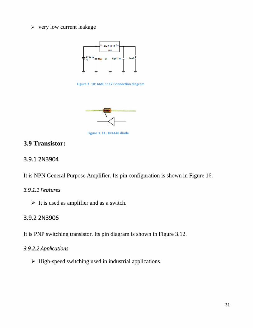
3.7 AME1117 (3.3V Voltage Regulator) ............................................................................................. 30
3.7.1 Application: ................................................................................................................................. 30
3.8 Diodes ............................................................................................................................................... 30
3.8.1 Description: ................................................................................................................................... 30
3.9 Transistor: ......................................................................................................................................... 31
3.9.1 2N3904 .......................................................................................................................................... 31
3.9.1.1 Features .................................................................................................................................. 31
3.9.2 2N3906 .......................................................................................................................................... 31
3.9.2.2 Applications ............................................................................................................................ 31
3.10 DLC (Data Link Connector) ........................................................................................................... 32
3.11 Bluetooth Serial Interface Module ................................................................................................. 32
3.12 Hardware Implementation .............................................................................................................. 34
3.12.1 Block Diagram ............................................................................................................................ 34
3.12.2 Circuit Diagram ........................................................................................................................... 34
Chapter 4 ................................................................................................................................................ 37
ERP System Module Development ........................................................................................................ 37
4.1 OpenERP (Odoo) System ................................................................................................................. 37
4.1.1 Proposed Work .............................................................................................................................. 38
4.2 Developing Module in OpenERP ..................................................................................................... 40
4.3 Installing a Module ........................................................................................................................... 40
4.4 Data Logging and Uploading Using Torque .................................................................................... 42
4.5 Importing Log File in OpenERP ...................................................................................................... 43
Chapter 5 ................................................................................................................................................ 45
Testing and Results ................................................................................................................................ 45
5.1 Testing OBDII Hardware ................................................................................................................. 45
5.1.1 Testing With Teraterm Terminal ................................................................................................... 45
5.1.2 Real Time Testing ......................................................................................................................... 46
5.1.3 Log File Data and Its Output ......................................................................................................... 51
7
Chapter 6 ................................................................................................................................................ 55
Application and Conclusion ................................................................................................................... 55
6.1 Applications: .................................................................................................................................... 55
6.1.1 User Applications .......................................................................................................................... 55
6.1.2 Enterprise applications .................................................................................................................. 55
6.2 Conclusion .................................................................................................................................. 55
6.3 Recommendation ........................................................................................................................ 56
Appendix A ............................................................................................................................................ 57
List of Standard PIDs and Mode of Communication .............................................................................. 57
Appendix B............................................................................................................................................. 68
Steps for Installing OpenERP in Ubuntu ................................................................................................. 68
Appendix C............................................................................................................................................. 77
Testing with TeraTerm Terminal ................................................................................................................ 77
Appendix D ............................................................................................................................................ 82
OBDII ....................................................................................................................................................... 82
OBDII Standard Connector and Protocols .............................................................................................. 83
Bibliography ............................................................................................................................................... 88
8
List of Figures
Chapter 1
Figure 1. 1: System Overview ..................................................................................................................... 10
Figure 1. 2: ECU and Sensor........................................................................................................................ 12
Figure 1. 3: Architecture of Diagnostic system........................................................................................... 15
Chapter 2
Figure 2. 1: Data Logging ...........................................................................................................................21
Chapter 3
Figure 3. 1: STN1110 IC Pins Configuration ..............................................................................................27
Figure 3. 2: ELM 327 IC .............................................................................................................................27
Figure 3. 3: STN1110 ..................................................................................................................................27
Figure 3. 4: LM339 IC ................................................................................................................................28
Figure 3. 5: LM339 IC pin Configuration ...................................................................................................28
Figure 3. 6: LM317 LD connection diagram ...............................................................................................28
Figure 3. 7: 5V Voltage Regulator ..............................................................................................................29
Figure 3. 8: MCP2551 Pin configuration ....................................................................................................29
Figure 3. 9: 7805 Connections diagram ......................................................................................................29
Figure 3. 10: 1N4148 diode .........................................................................................................................31
Figure 3. 11: AME 1117 Connection diagram ............................................................................................31
Figure 3. 14: 2N3904 Transistor pin diagram .............................................................................................32
Figure 3. 12: 2N3906 Transistor pin diagram .............................................................................................32
Figure 3. 13: DLC connector .......................................................................................................................32
Figure 3. 15: HC06 Bluetooth module pin configuration ............................................................................33
Figure 3. 16: HC06 Bluetooth module ........................................................................................................33
Figure 3. 17: HC06 Bluetooth Pin diagram .................................................................................................33
Figure 3. 18: Block diagram of the System .................................................................................................34
Figure 3. 19: 3D PCB Design ......................................................................................................................35
Figure 3. 20: Ares PCB Design ...................................................................................................................35
Figure 3. 21: Breadboard Design.................................................................................................................36
Chapter 4
Figure 4. 1: OpenERP (old name) Odoo (new name) Labels ......................................................................38
Figure 4. 2: Module in OpenERP/ Odoo .....................................................................................................38
Figure 4. 3: OpenERP Login .......................................................................................................................39
Figure 4. 4: Database management screen ..................................................................................................41
Figure 4. 5: Main Setup screen ....................................................................................................................41
Figure 4. 6: Torque Output ..........................................................................................................................43
Figure 4. 7: Importing log file .....................................................................................................................44
Figure 4. 8: Uploaded data in ERP Module.................................................................................................44
Chapter 5
9
Figure 5. 1: Serial Port Setup ......................................................................................................................45
Figure 5. 2: Terminal Setup .........................................................................................................................46
Figure 5. 3: Successful connection of Torque .............................................................................................47
Figure 5. 4: Connection Established ............................................................................................................49
Figure 5. 5: PIDs .........................................................................................................................................49
Figure 5. 6: Available Sensors and PIDs for Logging .................................................................................50
Figure 5. 7: Dashboard ................................................................................................................................50
Figure 5. 8: PIDs to Log files ......................................................................................................................51
Figure 5. 9: Log file containing different parameters information ..............................................................51
Appendix B
Figure Appendix B. 1: OpenERP.py ...........................................................................................................72
Figure Appendix B. 2: The Fleet info file ...................................................................................................73
Appendix D
Figure Appendix D. 1: DTC Specification ..................................................................................................87
List of Tables
Chapter 3
Table 3. 1: Comparison between STN1110 and ELM327 ..........................................................................26
Chapter 4
Table 4. 1: List of Fields..............................................................................................................................40
Appendix D
Table Appendix D. 1: DLC Pins Description ..............................................................................................83
Table Appendix D. 2: Protocol specification ..............................................................................................84
10
Chapter 1
Introduction
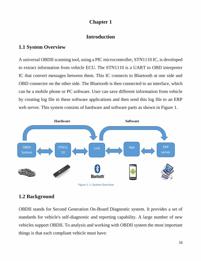
1.1 System Overview
A universal OBDII scanning tool, using a PIC microcontroller, STN1110 IC, is developed
to extract information from vehicle ECU. The STN1110 is a UART to OBD interpreter
IC that convert messages between them. This IC connects to Bluetooth at one side and
OBD connector on the other side. The Bluetooth is then connected to an interface, which
can be a mobile phone or PC software. User can save different information from vehicle
by creating log file in these software applications and then send this log file to an ERP
web server. This system consists of hardware and software parts as shown in Figure 1.
Hardware Software
1.2 Background
OBDII stands for Second Generation On-Board Diagnostic system. It provides a set of
standards for vehicle's self-diagnostic and reporting capability. A large number of new
vehicles support OBDII. To analysis and working with OBDII system the most important
things is that each compliant vehicle must have:
Link App ERP
server
STN11
10
OBDII
System
Figure 1. 1: System Overview
11
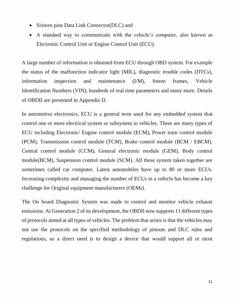
Sixteen pins Data Link Connector(DLC) and
A standard way to communicate with the vehicle’s computer, also known as
Electronic Control Unit or Engine Control Unit (ECU).
A large number of information is obtained from ECU through OBD system. For example
the status of the malfunction indicator light (MIL), diagnostic trouble codes (DTCs),
information inspection and maintenance (I/M), freeze frames, Vehicle
Identification Numbers (VIN), hundreds of real time parameters and many more. Details
of OBDII are presented in Appendix D.
In automotive electronics, ECU is a general term used for any embedded system that
control one or more electrical system or subsystem in vehicles. There are many types of
ECU including Electronic/ Engine control module (ECM), Power train control module
(PCM), Transmission control module (TCM), Brake control module (BCM / EBCM),
Central control module (CCM), General electronic module (GEM), Body control
module(BCM), Suspension control module (SCM). All these system taken together are
sometimes called car computer. Latest automobiles have up to 80 or more ECUs.
Increasing complexity and managing the number of ECUs in a vehicle has become a key
challenge for Original equipment manufacturers (OEMs).
The On board Diagnostic System was made to control and monitor vehicle exhaust
emissions. At Generation 2 of its development, the OBDII now supports 11 different types
of protocols aimed at all types of vehicles. The problem that arises is that the vehicles may
not use the protocols on the specified methodology of pinouts and DLC rules and
regulations, so a direct need is to design a device that would support all or most
12
communication protocols and have a transfer and scan mechanism for successfully
establishing communication to any vehicle [1].
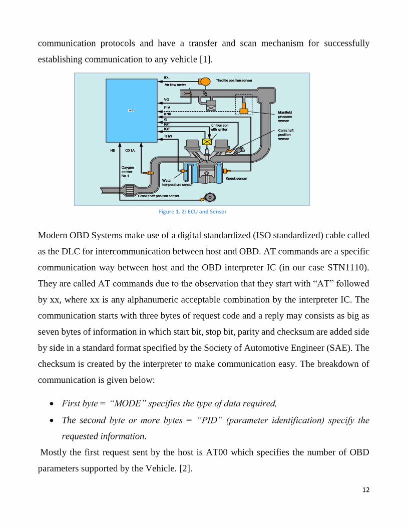
Modern OBD Systems make use of a digital standardized (ISO standardized) cable called
as the DLC for intercommunication between host and OBD. AT commands are a specific
communication way between host and the OBD interpreter IC (in our case STN1110).
They are called AT commands due to the observation that they start with “AT” followed
by xx, where xx is any alphanumeric acceptable combination by the interpreter IC. The
communication starts with three bytes of request code and a reply may consists as big as
seven bytes of information in which start bit, stop bit, parity and checksum are added side
by side in a standard format specified by the Society of Automotive Engineer (SAE). The
checksum is created by the interpreter to make communication easy. The breakdown of
communication is given below:
First byte = “MODE” specifies the type of data required,
The second byte or more bytes = “PID” (parameter identification) specify the
requested information.
Mostly the first request sent by the host is AT00 which specifies the number of OBD
parameters supported by the Vehicle. [2].
Figure 1. 2: ECU and Sensor

13
ERP system is a platform used for business management. It is an integrated application
that an organization can use to store and manage data. ERP system provides a real-time
view of fundamental business processes by using common database. It eases information
flow between all business function and manages connections to outside stakeholders.
1.3 Objectives and Motivation
There are different OBDII Scan tools available for vehicle diagnostics, but these are
specific in their functions and are compatible only with vehicles having the same OBDII
standard as scanning device have. Also, some of these diagnostic tools have high cost, not
too efficient nor user friendly. Also, software solutions for vehicle management and
performance optimization are costly. Therefore, project objectives are:
1. A low cost universal OBDII scanning device that is compatible with every type of
vehicle, for real time monitoring and optimization of automobile’s performance.
2. To develop a vehicle performance optimization module in OpenERP.
1.4 System Architecture
Vehicle health and positioning telemetry system is a way of monitoring status of engine
condition, location, movements, status and behaviour of a vehicle or fleet of vehicles. This
is achieved through a remote collection of data through a combination of hardware devices
installed in a vehicle, communication technologies and software’s. With the advancement
of new paradigms of technology, it is becoming easy to manage and control vehicles
through telemetric systems. Enterprises having large fleet of vehicles are facing
challenges of management and performance optimization. Therefore, a telemetry system
is developed for optimal management through real time monitoring of vehicle health and
its positioning.
Hardware and software platforms are required for extracting, logging, reporting and
analysis of vehicle health and other data. This data from vehicle is acquired through On-
Board Diagnostic (OBD) system &Engine control Unit (ECU). There are several sensors
14
available in the vehicles which are connected to the ECU. One can communicate with an
ECU through connecting an OBD scanning tool in OBD data link connector or port, as
OBD system has then made it easy to extract data from the engine. The latest technology
in use is OBD-II and there is a 16 pin OBD-II connector, in most of the cars manufactured
after 1996 models. One can view information such as mileage, mpg, fuel consumption,
error codes, air/fuel ratio, timing and many other parameters depending on the sensors
available in the vehicle to see the performance of a vehicle.
Communication technologies and software’s are used to view this OBD system data.
There are many ways to read the data using android device or desktop application. A
mobile, desktop or web application connects to the OBD scanner through a Bluetooth or
WI-FI. These applications are used to get data from OBD scanner. Also, the user is able
to save the data into log files on the mobile device or PC. Similarly, the data can be sent
to the Enterprise Resource Planning (ERP) system in an organization, just in time to the
repair and maintenance department, where it is evaluated to identify the faults or to detect
anomalies, and can help for managing the performance of vehicles in an optimal manner.
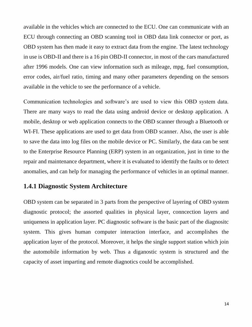
1.4.1 Diagnostic System Architecture
OBD system can be separated in 3 parts from the perspective of layering of OBD system
diagnostic protocol; the assorted qualities in physical layer, conncection layers and
uniqueness in application layer. PC diagnostic software is the basic part of the diagnositc
system. This gives human computer interaction interface, and accomplishes the
application layer of the protocol. Moreover, it helps the single support station which join
the automobile information by web. Thus a diganostic system is structured and the
capacity of asset imparting and remote diagnotics could be accomplished.

15
Vehicle Communication interface (VCI) system is the bridge which connects the vehicle
diagnoictic system and host computer diagnosis system. It implements the conversion of
different communication protocols between network and host computer diagnosis system.
When the car is moving, ECU constantly mointors the input information of sensors and
actuators by CAN. When it detects one or more fault information, it will lit up the MIL
and then store the fault information in the form of diagnostic codes into memory. When
diagnosing fautls, diagnostic devices communicate with ECU and get the storage fault
codes and other information, according to diagnostic protocols used. Architecture of the
over all system is shown in Figure 3.
1.4.2 Logging Data
Data of available sensor can be logged and stored in log file for further analysis. The file
is in CSV format generally store in the log folder of the available software.
Figure 1. 3: Architecture of Diagnostic system
16
1.5 Significance of Proposed Work
OBDII system requires all light duty cars and trucks to monitor specific systems using
generic criteria for evaluation and reporting of system status, and for indicating problems
to the motorist and/or technician. OBDII code provides definitions, description, symptoms
and a possible solution of vehicles faults.
Using this OBDII scan tool one can easily diagnose vehicle and can avoid different
accident due to hide failures in vehicle. Also future faults in vehicle are easily diagnosed.
Also for fleet management organization, it provide a better and sophisticated way of
diagnosing and monitoring status of engine condition, location, movements, status and
behaviour of a vehicle.
17
Chapter 2
Literature Review
Automization of vehicle is very important field and is started since 1990s. Many scientist
contributes in this area and achieve many important goals. Lots of hardware are made and
many techniques and methods are applied to achieve efficiency in automization of
vehicles. In this chapter, few methods and techniques of onboard diagnostic system
engineering is briefly described.
This chapter mainly focus on description about related work on OBDII system and OBDII
scanning devices. A sketch of ERP system and its related work are also defined. Literature
review covers the OBDII system analysis, Data Collection, Monitoring Performance,
Efficiency analysis and actions based on test data, Fleet management, Managing
Teenage/Amateur Drivers, Preventive measures, Proactive measures.
2.1 Universal OBDII Scan tool
On-Board Diagnostic System (OBD) is a very important component in automization of
vehicles and machinery. Jie and H. Fuwu (2010, March) Developed PC-Based
Automobile Diagnostic System Based on OBD System. Automobile diagnosis has been
taken into considerations at the start of 1970 in the form of sensors embedded in them.
Today, the international manufacturers all over the world have successfully adapted OBD
II as the standard for checking, maintaining, diagnosing and removing faults in
automobiles in order to eliminate environmental hazards due to emissions of toxic gases
and particles.
2.2 A Prototype System
Roscaet. Al (2011) developed and described the design, development, and data processing
characteristics of the prototype system [2]. A microcomputer-based multichannel data
18
acquisition system is used to acquire high frequency transient information typified by, but
not limited to, automotive vehicle crash test applications. The system was designed to be
mounted on the test vehicle during a vehicle crash, will accommodate up to 240 channels.
Each channel is comprised of a stand-alone microcomputer, memory for data storage,
signal conditioning for piezo-resistive transducers, automatic calibration and zero offsets,
and programmable gain amplifier. The microcomputer is based upon a Motorola
6801/68701 microcomputer.
2.3 Elimination of Fault Codes
The On-board Diagnostic (OBD) standards were released and established as a measure to
get control over the vehicular emissions. The Engine Control Unit (ECU) constantly
monitors the various aspects of the vehicle for any possible faults such as an engine
misfire, or a high temperature or a failure of the torque system. Upon failure or detection
of an error, the ECU stores that data in a memory location of the ECU called as the freeze
frame memory. Freeze frame is a snapshot of the information of all the sensors at the time
of occurrence of a fault.
If we focus on the preventive side of the possible applications of a remote data scanner
device, there is almost no or very scarce work available. OBDII is specialized in a sense
that it has assigned alphanumeric codes to errors that may occur in the automobile. So at
the occurrence of the error, the info is stored and a Diagnostic Trouble Code is set in the
ECU which can be read in the memory of the ECU by the scanner device and then try to
eliminate it [3]. The ECU of a vehicle stores only faults and DTCs when there is an actual
error in the vehicle. The device:
1. Detect and transmit fault codes to the host
2. Predict faults that may occur with time

19
Global Information System (GIS) is utilized in the vehicle and the location of the vehicle
is also being transmitted to the server through cell-phone’s General Packet Radio Service
(GPRS) system [4].
2.4 Fleet Monitoring
Siegel, J. E. (2011) Design and developed a remotely reconfigurable vehicle telemetry
system for consumer and government applications. Government and enterprises are
seeking ways to control vehicle through online monitoring system based on the social
determinants, cost optimization, automobile’s health. This system will provide ways of
billing, monitoring, safety and control over disaster and accident preventive methods as
well as optimization techniques for automobiles services. Consumers will appreciate the
amount of information that their cars will feedback to them through mobile phones or
web-based applications.
Few aspects On-Board Diagnostic System try to cover.
Data Collection
Monitoring Performance
Efficiency analysis and actions based on test data
Fleet management
Managing Teenage/Amateur Drivers
Preventive measures
Proactive measures.
No such system is made until now which can tackle all the above mentioned aspects.
Presently just handheld standalone tools are present for diagnostics purposes of detecting
faults and diagnostics trouble codes associated with automobile control units. Problem
with this handheld standalone device are:
Engine parameters measurement is not done freely for calculations purposes.
Real time feedback is not provided [5].

20
United States Environmental Protection Agency (EPA) has mandated that the DTCs
should be set only when there is emissions beyond control ranges. But manufacturers have
programmed their vehicles to trigger DTC events based on any faults in the vehicle.
Consider a scenario in which no DTC is set but there is a definite problem in the vehicle’s
functioning. So in that case, we may need data fetched from the OBD scanner for the
purpose of eliminating and correcting faults for optimization and preventive measures. A
technician may sometime use his common sense and intuition to detect faults based on
experience. But these methods are time consuming and tiring.
So a universal scanner is needed with advanced diagnostics capabilities to better cope with
these MIL, DTC and other unknown errors for the health and safety and performance
optimization of machinery [6]. OBD is responsible for monitoring:
Catalytic converters
Evaporative control system
Emissions control system
Oxygen sensors
Emissions related sensors and actuators
Engine misfire
Exhaust gas recirculation (EGR)
Fuel system
Closed loop system performance etc. [7]
2.5 Standard Protocols
OBD-II Standards are installed inside the Engine Control Unit (ECU) known as power
train control module of the vehicle (PCM). OBD-II scan tool is used to extract useful
information from vehicle. Some of OBD-II scan tool related devices are available in the
market e.g. personal digital assistant Dyno/ OBD-II scan tool, Car Chip fleet, Driver Right
600, Scan Gauge. But there are some limitations in these devices. So to supports all the
21
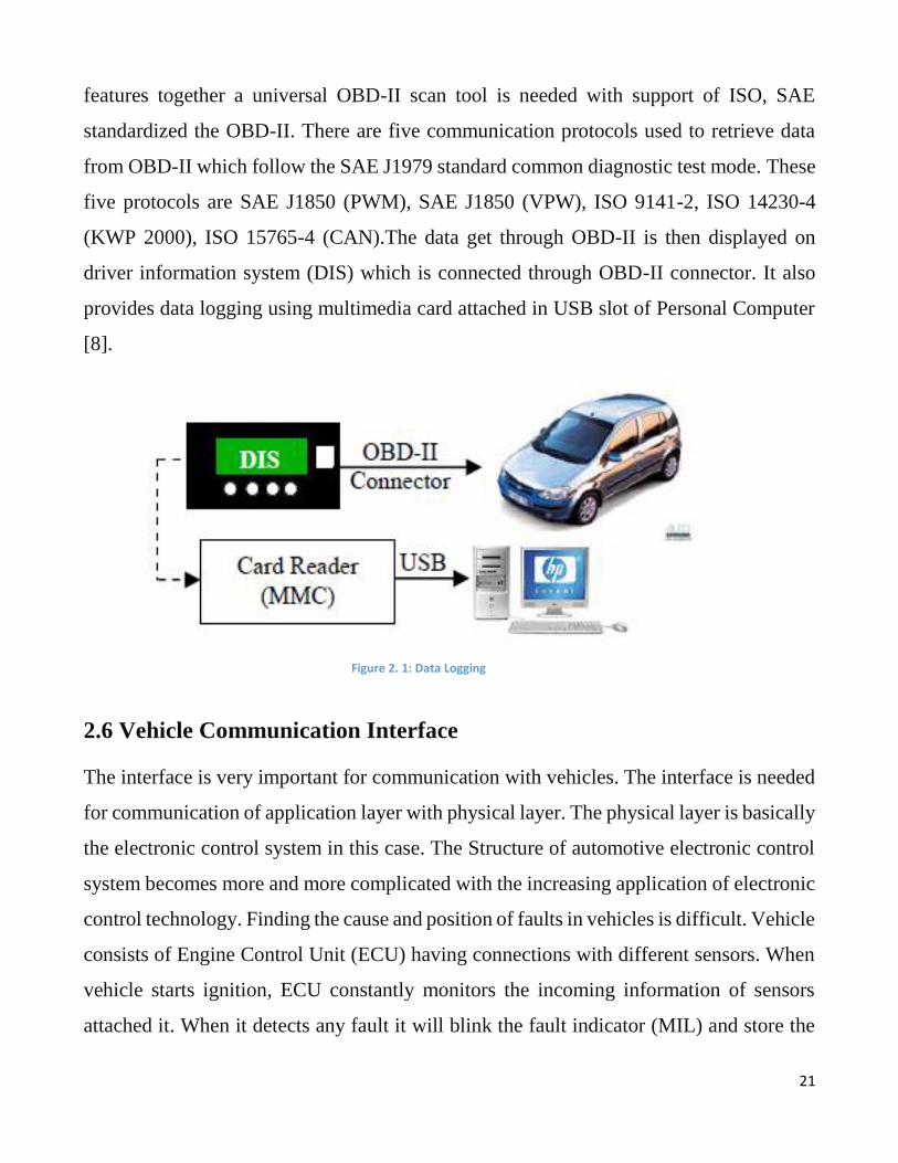
features together a universal OBD-II scan tool is needed with support of ISO, SAE
standardized the OBD-II. There are five communication protocols used to retrieve data
from OBD-II which follow the SAE J1979 standard common diagnostic test mode. These
five protocols are SAE J1850 (PWM), SAE J1850 (VPW), ISO 9141-2, ISO 14230-4
(KWP 2000), ISO 15765-4 (CAN).The data get through OBD-II is then displayed on
driver information system (DIS) which is connected through OBD-II connector. It also
provides data logging using multimedia card attached in USB slot of Personal Computer
[8].
2.6 Vehicle Communication Interface
The interface is very important for communication with vehicles. The interface is needed
for communication of application layer with physical layer. The physical layer is basically
the electronic control system in this case. The Structure of automotive electronic control
system becomes more and more complicated with the increasing application of electronic
control technology. Finding the cause and position of faults in vehicles is difficult. Vehicle
consists of Engine Control Unit (ECU) having connections with different sensors. When
vehicle starts ignition, ECU constantly monitors the incoming information of sensors
attached it. When it detects any fault it will blink the fault indicator (MIL) and store the
Figure 2. 1: Data Logging

22
incoming fault information in the memory in the form of diagnostic codes. When
diagnostic devices communicate with ECU it will retrieve the storage fault diagnostic
codes and other information from the memory, according to diagnostic protocols occur in
diagnostic devices. OBD systems can analysis different kinds of diagnostic protocol use
on OBD diagnostic system. Presently, widely used diagnostic equipment is OBD-II.
Desktop based diagnostic software is used to diagnose the system which is the main part
of diagnostic system. It provides human-computer communication interface. The vehicle
diagnostic system and diagnostic software can be connected with the help of vehicle
Communication Interface (VCI) system. This system is used for data transmission as well
as conversion of different communication protocols between network and computer [9].
There are three sub module of Vehicle Communication Interface (VCI) system.
1. Protocol conversion function module: This module is used for level transmission
between vehicles protocol and computer (Host).
2. Host microcontroller module: This module is used for analysis the on board data
and send message to Host and at the same time receive data from host.
3. USB bridge module: This module is used to transfer serial data to USB data and
ensure the communication between microcontroller and the Computer (host).
2.7 ERP System Characteristics
ERP stands for Enterprise Resource Planning, ERP is basically known as Enterprise
Information System. It has great advantages over the manual information system e.g.
efficient monitoring over all the resources of enterprise, timely scheduled maintenance
and management, human resource planning, project planning, Accounts and financial
planning and monitoring etc. Because of such great advantages ERP system gets very
importance in the industries, and most of the companies adopts ERP systems.
Companies are usually triggered by the appearance of some symptoms to adopt ERP
systems. Such symptoms can be high levels of inventory, mismatched stock, lack of
23
coordinated activity, excessive need for reconciliation, flouting of controls, poor customer
response levels, poor cost control, lack of efficiency and lack of a total visibility into the
overall supply chain performance [22]. Shehab et al. (2004) argue that the ERP package
selection process is deceptively difficult.
There is a concept used in software engineer’s community known as Open Source
Community. Open Source Software (OSS) now exists for many of the most common types
of software ranging from servers to office programs. OSS means that the source code is
available for programmers to view, read, modify and re-distribute. OS software are given
GPL (General Public Licence) Licence. Same concept is also present in ERP systems i.e.
Openbravo, tryton, xTuple ERP, AvERP, OpenERP (now known as ODOO) etc. An ERP
system integrates business processes throughout an organization, thereby improving
speed, efficiency and accessibility of information flows. This offers benefits such as
lowered cost for software, along with flexibility and avoidance of vendor lock-in.
According to Umble et al. ( “a successful ERP project can cut the fat out of operating
costs, generate more accurate demand forecast, speed production cycles, and greatly
enhance customer service”. The evaluation of the chosen Open Source ERP systems is
going to be performed based on a set of dimensions and features. The defined set of
dimensions is inspired from the organizations’ needs [23].
2.8 Open ERP (ODOO)
The concept of OpenERP and development of application begins 2005, and AGPL licence
was given. The development of software is done mostly in Python, because the python-
based system is familiar to both Windows and Linux operating systems. It uses
PostgreSQL database and for export and import CSV format is used.
There are around 300 modules present in ODOO with different functionalities. Few
modules are automatically installed during installation of ODOO system. Installing
24
additional module along with their visual presentation data provides an appropriate way
of exploring the entire basic system. The update facility is also available but it depends
on the client’s choice, whether the client want to update the module automatically or
manually or may be the client do not want any update for specific module. That is why
the update is left on the user’s choice.

25
Chapter 3
Hardwar Design and Implementation
Hardware is the core part of our project. The hardware consists of multiple components
where STN1110 IC is the main component of hardware. The function and structure of
each component are presented in the following section. Temporary testing and
implementation of this hardware is carried out using a breadboard. Simulation and
Schematic of this system was designed using different software’s such as Proteus, Eagle
and Multisim etc.
3.1 Main Hardware Components Used
The following components are used during hardware implementation:
STN1110 IC, LM399PWR IC, LM317LD IC, MCP2551 IC,78MO5 IC, AME1117 IC,
1N4148 Diodes, 2N3904 and 2N3906 Transistors, DLC and various resistors.
3.2 STN1110 (Multiprotocol OBD to UART Interpreter IC)
The smallest and lowest cost PIC multiprotocol OBD to UART interpreter IC is STN1110.
With the help of STN1110 one can easily access vehicle data such as diagnostic trouble
codes, MIL status, Inspection and Maintenance information. ELM327 command set has
full supported by STN1110.This IC is based on PIC micro-controller which is
implemented on PIC24HJ128GP502 reference family. It support all AT command like
ELM327. It also supports ST commands sets.
3.2.1 Features:
This IC is supported all legislated OBDII protocols. Such as
ISO 15765-4 (CAN)
ISO 14230-4 (keyword protocol 2000)
ISO 9141-2 (Asian, European, Chrysler vehicles)
26
SAE J1850 VPW (GM vehicles)
It also has support for non-legislated OBDII protocols. Such as
ISO 15765
ISO 11898 (raw CAN)
And also support for SAE J1939 OBDII protocol.
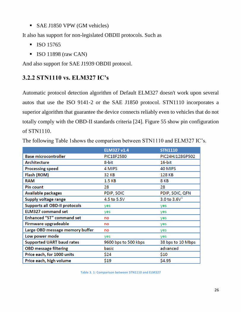
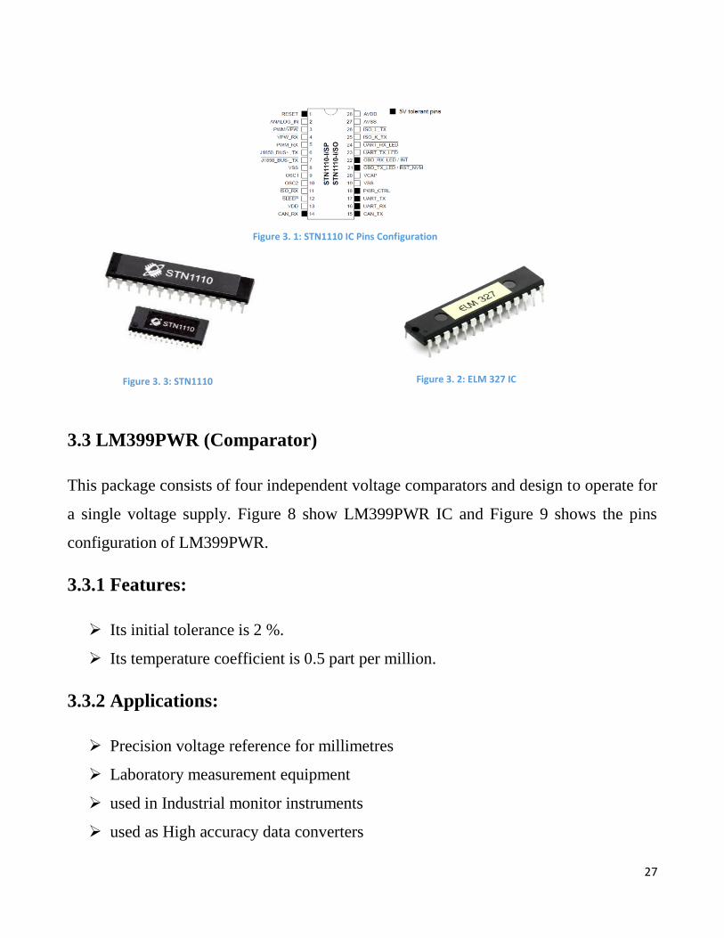
3.2.2 STN1110 vs. ELM327 IC’s
Automatic protocol detection algorithm of Default ELM327 doesn't work upon several
autos that use the ISO 9141‐2 or the SAE J1850 protocol. STN1110 incorporates a
superior algorithm that guarantee the device connects reliably even to vehicles that do not
totally comply with the OBD‐II standards criteria [24]. Figure 55 show pin configuration
of STN1110.
The following Table 1shows the comparison between STN1110 and ELM327 IC’s.
Table 3. 1: Comparison between STN1110 and ELM327
27
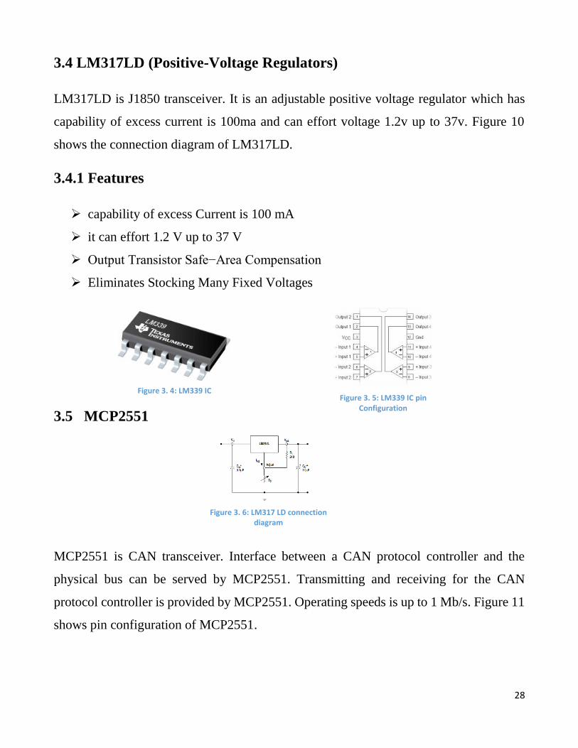
3.3 LM399PWR (Comparator)
This package consists of four independent voltage comparators and design to operate for
a single voltage supply. Figure 8 show LM399PWR IC and Figure 9 shows the pins
configuration of LM399PWR.
3.3.1 Features:
Its initial tolerance is 2 %.
Its temperature coefficient is 0.5 part per million.
3.3.2 Applications:
Precision voltage reference for millimetres
Laboratory measurement equipment
used in Industrial monitor instruments
used as High accuracy data converters
Figure 3. 1: STN1110 IC Pins Configuration
Figure 3. 3: STN1110 Figure 3. 2: ELM 327 IC
28
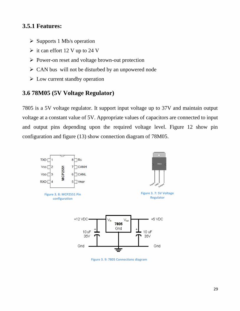
3.4 LM317LD (Positive-Voltage Regulators)
LM317LD is J1850 transceiver. It is an adjustable positive voltage regulator which has
capability of excess current is 100ma and can effort voltage 1.2v up to 37v. Figure 10
shows the connection diagram of LM317LD.
3.4.1 Features
capability of excess Current is 100 mA
it can effort 1.2 V up to 37 V
Output Transistor Safe−Area Compensation
Eliminates Stocking Many Fixed Voltages
3.5 MCP2551
MCP2551 is CAN transceiver. Interface between a CAN protocol controller and the
physical bus can be served by MCP2551. Transmitting and receiving for the CAN
protocol controller is provided by MCP2551. Operating speeds is up to 1 Mb/s. Figure 11
shows pin configuration of MCP2551.
Figure 3. 4: LM339 IC Figure 3. 5: LM339 IC pin
Configuration
Figure 3. 6: LM317 LD connection diagram
29
3.5.1 Features:
Supports 1 Mb/s operation
it can effort 12 V up to 24 V
Power-on reset and voltage brown-out protection
CAN bus will not be disturbed by an unpowered node
Low current standby operation
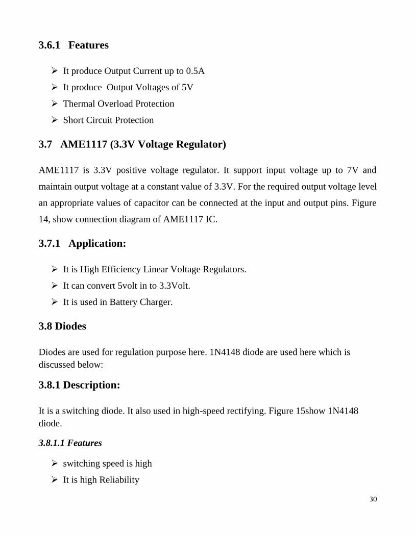
3.6 78M05 (5V Voltage Regulator)
7805 is a 5V voltage regulator. It support input voltage up to 37V and maintain output
voltage at a constant value of 5V. Appropriate values of capacitors are connected to input
and output pins depending upon the required voltage level. Figure 12 show pin
configuration and figure (13) show connection diagram of 78M05.
Figure 3. 8: MCP2551 Pin configuration
Figure 3. 7: 5V Voltage Regulator
Figure 3. 9: 7805 Connections diagram
30
3.6.1 Features
It produce Output Current up to 0.5A
It produce Output Voltages of 5V
Thermal Overload Protection
Short Circuit Protection
3.7 AME1117 (3.3V Voltage Regulator)
AME1117 is 3.3V positive voltage regulator. It support input voltage up to 7V and
maintain output voltage at a constant value of 3.3V. For the required output voltage level
an appropriate values of capacitor can be connected at the input and output pins. Figure
14, show connection diagram of AME1117 IC.
3.7.1 Application:
It is High Efficiency Linear Voltage Regulators.
It can convert 5volt in to 3.3Volt.
It is used in Battery Charger.
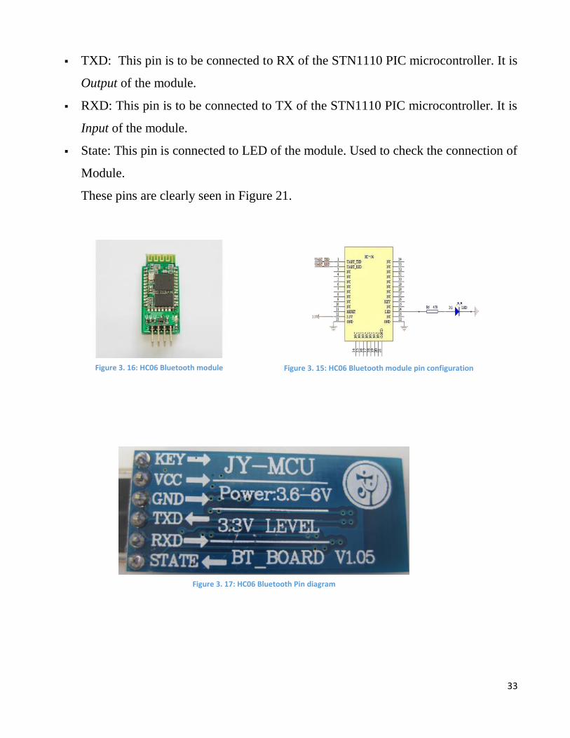
3.8 Diodes
Diodes are used for regulation purpose here. 1N4148 diode are used here which is
discussed below:
3.8.1 Description:
It is a switching diode. It also used in high-speed rectifying. Figure 15show 1N4148
diode.
3.8.1.1 Features
switching speed is high
It is high Reliability
31
very low current leakage
3.9 Transistor:
3.9.1 2N3904
It is NPN General Purpose Amplifier. Its pin configuration is shown in Figure 16.
3.9.1.1 Features
It is used as amplifier and as a switch.
3.9.2 2N3906
It is PNP switching transistor. Its pin diagram is shown in Figure 3.12.
3.9.2.2 Applications
High-speed switching used in industrial applications.
Figure 3. 10: AME 1117 Connection diagram
Figure 3. 11: 1N4148 diode

32
3.10 DLC (Data Link Connector)
Data Link Connector is connected under the dash at the steering column. It is sixteen pins
diagnostic connector used for connection with ECU. It interfaces the OBDII scan tool
with the vehicle computer to access On-Board Diagnostic and live data streams.
3.11 Bluetooth Serial Interface Module
There is different level of Bluetooth module.HC-06 is civil level module. It is used for
converting serial port to Bluetooth. There are two modes of Bluetooth modules master
and slaver device. The HC-06 module only can be a slave. It is shown in Figure 3.15, and
its pin configuration is shown in Figure 3.16.
KEY: This pin need to pull-up while power-on-reset of the module to enforce AT
mode.
VCC: It indicated Voltage. It worked for both 3.3V and 5V.
GND: It indicates Ground.
Figure 3. 13: 2N3904 Transistor pin diagram Figure 3. 12: 2N3906 Transistor pin diagram
Figure 3. 14: DLC connector
33
TXD: This pin is to be connected to RX of the STN1110 PIC microcontroller. It is
Output of the module.
RXD: This pin is to be connected to TX of the STN1110 PIC microcontroller. It is
Input of the module.
State: This pin is connected to LED of the module. Used to check the connection of
Module.
These pins are clearly seen in Figure 21.
Figure 3. 16: HC06 Bluetooth module Figure 3. 15: HC06 Bluetooth module pin configuration
Figure 3. 17: HC06 Bluetooth Pin diagram
34
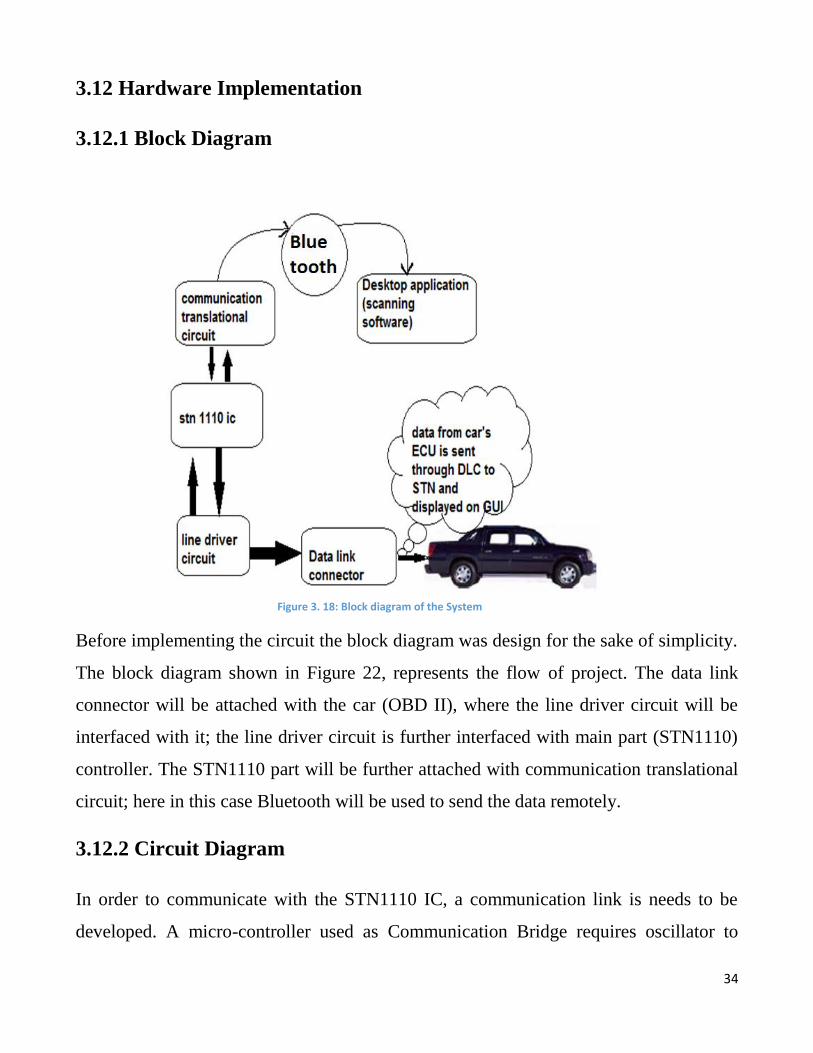
3.12 Hardware Implementation
3.12.1 Block Diagram
Before implementing the circuit the block diagram was design for the sake of simplicity.
The block diagram shown in Figure 22, represents the flow of project. The data link
connector will be attached with the car (OBD II), where the line driver circuit will be
interfaced with it; the line driver circuit is further interfaced with main part (STN1110)
controller. The STN1110 part will be further attached with communication translational
circuit; here in this case Bluetooth will be used to send the data remotely.
3.12.2 Circuit Diagram
In order to communicate with the STN1110 IC, a communication link is needs to be
developed. A micro-controller used as Communication Bridge requires oscillator to
Figure 3. 18: Block diagram of the System
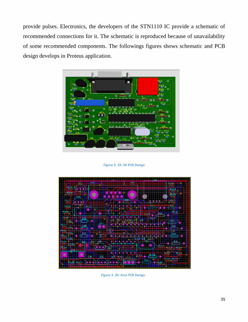
35
provide pulses. Electronics, the developers of the STN1110 IC provide a schematic of
recommended connections for it. The schematic is reproduced because of unavailability
of some recommended components. The followings figures shows schematic and PCB
design develops in Proteus application.
Figure 3. 19: 3D PCB Design
Figure 3. 20: Ares PCB Design
36
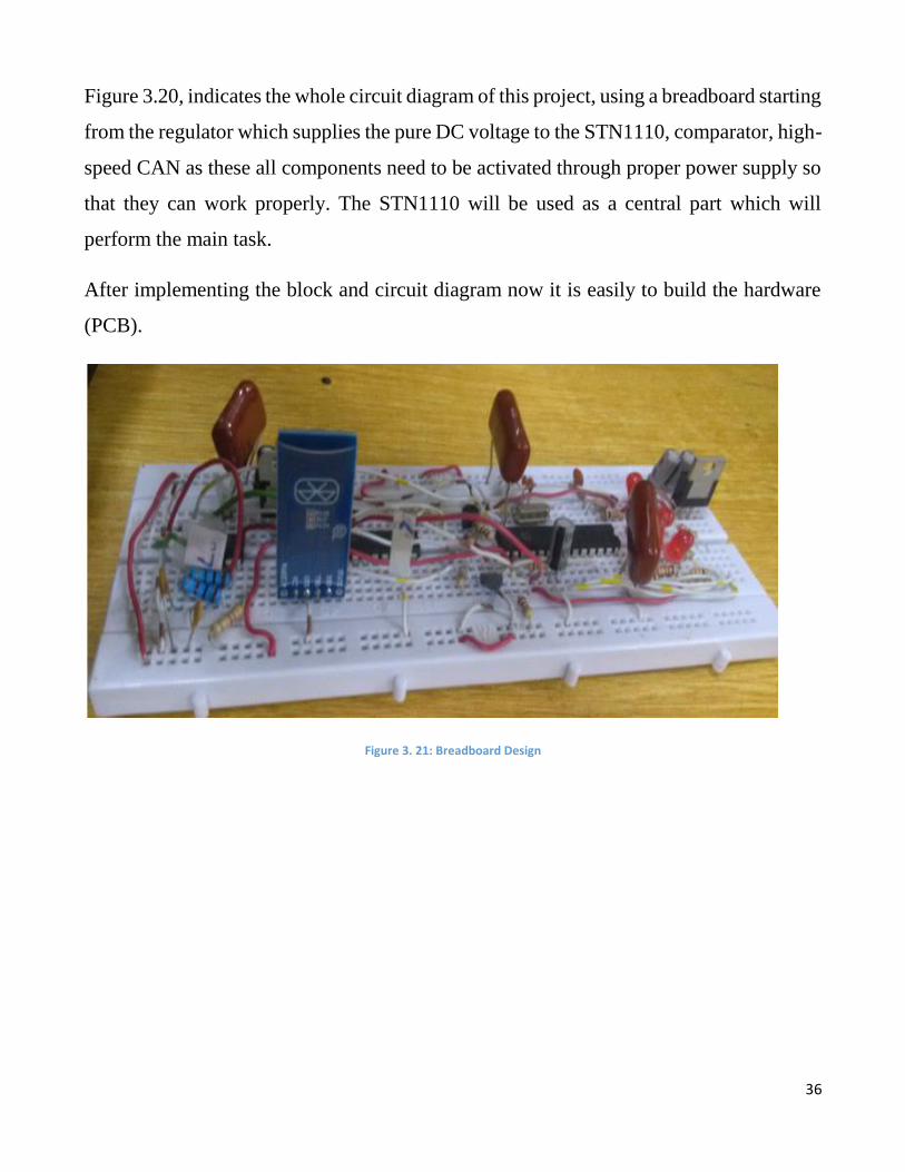
Figure 3.20, indicates the whole circuit diagram of this project, using a breadboard starting
from the regulator which supplies the pure DC voltage to the STN1110, comparator, high-
speed CAN as these all components need to be activated through proper power supply so
that they can work properly. The STN1110 will be used as a central part which will
perform the main task.
After implementing the block and circuit diagram now it is easily to build the hardware
(PCB).
Figure 3. 21: Breadboard Design

37
Chapter 4
ERP System Module Development
Enterprise Resource Planning (ERP) is business management software. This is an
integrated application that an organization can use to store and accomplish data from every
stage of business, including all sorts of product planning and development. ERP provides
a real time view of core business processes by using common database. It eases
information flow between all business function and manages connections to outside
stakeholders.
4.1 OpenERP (Odoo) System
ERP system is a platform used for business management. It is an integrated application
that an organization can use to store and manage data. ERP system provides a real time
view of fundamental business processes by using common database.
Organizations are usually triggered by the appearance of some symptoms to adopt ERP
systems. Such symptoms can be high levels of inventory, mismatched stock, lack of
coordinated activity, excessive need for reconciliation, flouting of controls, poor customer
response levels, poor cost control, lack of efficiency and lack of a total visibility into the
overall supply chain performance. Open source software (OSS) now exists for many of
the most common types of software ranging from servers to office programs. OSS means
that the source code is available for programmers to view, read, modify and re-distribute.
An OpenERP system integrates business processes throughout an organization, thereby
improving speed, efficiency and accessibility of information flows. Organizations require
a cost effective business management solution that enables control and efficiencies, so
OpenERP is a business management solution. It requires free software licenses and is
platform independent. OpenERP is free to use and share. OpenERP featuring HR,
Manufacturing, CRM, Accounting, Sales, Warehouse Management and more. It is based

38
on a modular, intuitive and scalable Rapid Application Development (RAD) framework
which is written in Python.
4.1.1 Proposed Work
The task is to make the data online available, which we receive from OBDII scan tool.
For this we choose OpenERP system. As it is an open source, so it is easily customized
and make data online available in OpenERP system. For receiving data in OpenERP, we
have to develop a module in it. OpenERP has built-in APIs, by using which we can easily
develop a module in minimum time. Module contains different directories, folders and
files (.py, .xml etc.) which contain codes for module view, interface, database connection
and entry of data to database.
The basic module structure is shown in Figure 4.2.
To install OpenERP v7, requires
Windows7 or
Ubuntu 12.04
Figure 4. 1: OpenERP (old name) Odoo (new name) Labels
Figure 4. 2: Module in OpenERP/ Odoo
39
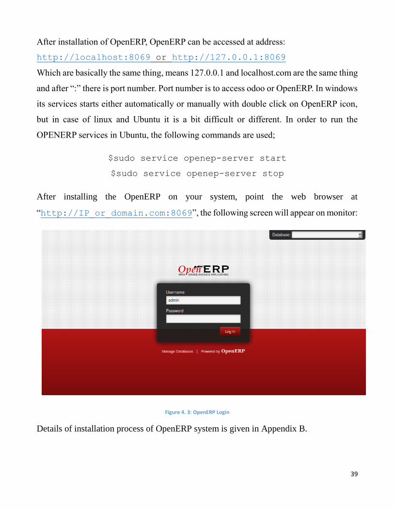
After installation of OpenERP, OpenERP can be accessed at address:
http://localhost:8069 or http://127.0.0.1:8069
Which are basically the same thing, means 127.0.0.1 and localhost.com are the same thing
and after “:” there is port number. Port number is to access odoo or OpenERP. In windows
its services starts either automatically or manually with double click on OpenERP icon,
but in case of linux and Ubuntu it is a bit difficult or different. In order to run the
OPENERP services in Ubuntu, the following commands are used;
$sudo service openep-server start
$sudo service openep-server stop
After installing the OpenERP on your system, point the web browser at
“http://IP_or_domain.com:8069”, the following screen will appear on monitor:
Figure 4. 3: OpenERP Login
Details of installation process of OpenERP system is given in Appendix B.
40
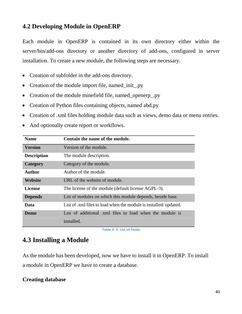
4.2 Developing Module in OpenERP
Each module in OpenERP is contained in its own directory either within the
server/bin/add-ons directory or another directory of add-ons, configured in server
installation. To create a new module, the following steps are necessary.
Creation of subfolder in the add-ons directory.
Creation of the module import file, named_init_.py
Creation of the module minefield file, named_openerp_.py
Creation of Python files containing objects, named abd.py
Creation of .xml files holding module data such as views, demo data or menu entries.
And optionally create report or workflows.
Name Contain the name of the module.
Version Version of the module.
Description The module description.
Category Category of the module.
Author Author of the module.
Website URL of the website of module.
License The license of the module (default license AGPL-3).
Depends List of modules on which this module depends, beside base.
Data List of .xml files to load when the module is installed/ updated.
Demo List of additional .xml files to load when the module is
installed.
Table 4. 1: List of Fields
4.3 Installing a Module
As the module has been developed, now we have to install it in OpenERP. To install
a module in OpenERP we have to create a database.
Creating database
41
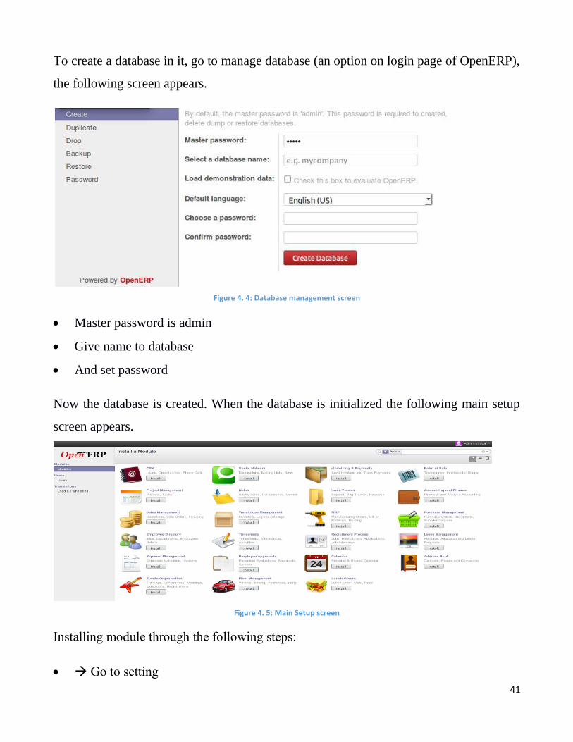
To create a database in it, go to manage database (an option on login page of OpenERP),
the following screen appears.
Figure 4. 4: Database management screen
Master password is admin
Give name to database
And set password
Now the database is created. When the database is initialized the following main setup
screen appears.
Figure 4. 5: Main Setup screen
Installing module through the following steps:
Go to setting
42
user
switch user to admin
check the technical features in access rights
save
We obtain some additional options. Now go to update module list, then installed modules,
remove the installed option from search bar and write name of module to search. The
module become visible and can be installed.
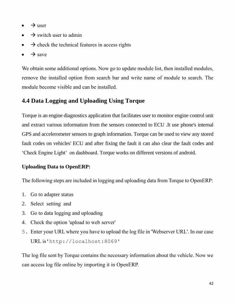
4.4 Data Logging and Uploading Using Torque
Torque is an engine diagnostics application that facilitates user to monitor engine control unit
and extract various information from the sensors connected to ECU .It use phone's internal
GPS and accelerometer sensors to graph information. Torque can be used to view any stored
fault codes on vehicles' ECU and after fixing the fault it can also clear the fault codes and
‘Check Engine Light’ on dashboard. Torque works on different versions of android.
Uploading Data to OpenERP:
The following steps are included in logging and uploading data from Torque to OpenERP:
1. Go to adapter status
2. Select setting and
3. Go to data logging and uploading
4. Check the option 'upload to web server'
5. Enter your URL where you have to upload the log file in 'Webserver URL'. In our case
URL is'http://localhost:8069'
The log file sent by Torque contains the necessary information about the vehicle. Now we
can access log file online by importing it in OpenERP.
43
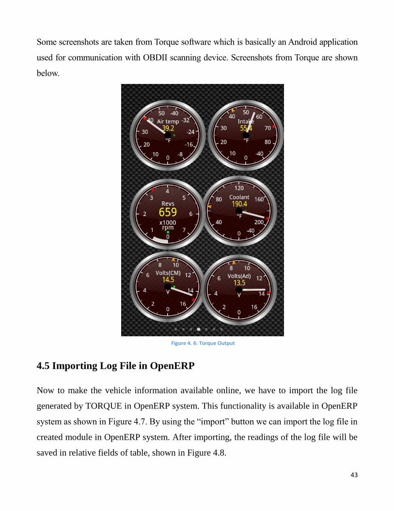
Some screenshots are taken from Torque software which is basically an Android application
used for communication with OBDII scanning device. Screenshots from Torque are shown
below.
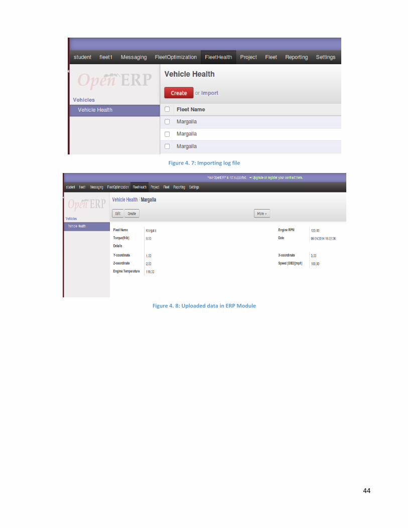
4.5 Importing Log File in OpenERP
Now to make the vehicle information available online, we have to import the log file
generated by TORQUE in OpenERP system. This functionality is available in OpenERP
system as shown in Figure 4.7. By using the “import” button we can import the log file in
created module in OpenERP system. After importing, the readings of the log file will be
saved in relative fields of table, shown in Figure 4.8.
Figure 4. 6: Torque Output
44
Figure 4. 7: Importing log file
Figure 4. 8: Uploaded data in ERP Module
45
Chapter 5
Testing and Results
5.1 Testing OBDII Hardware
To work with OBDII prototype, it need to be tested first, to make sure that the hardware
circuitry, serial communication as well as the signaling protocol worked fine. To do so a
terminal software called Teraterm is used. After successful testing the hardware is then
apply on vehicle in real time which gives the correct measurement.
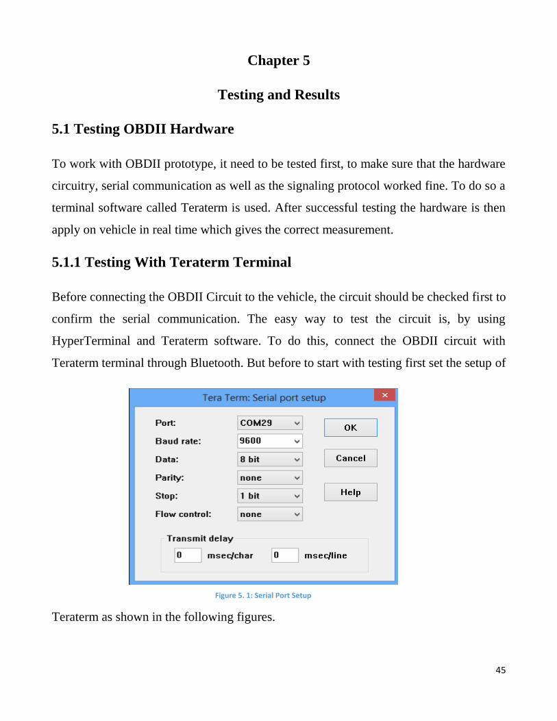
5.1.1 Testing With Teraterm Terminal
Before connecting the OBDII Circuit to the vehicle, the circuit should be checked first to
confirm the serial communication. The easy way to test the circuit is, by using
HyperTerminal and Teraterm software. To do this, connect the OBDII circuit with
Teraterm terminal through Bluetooth. But before to start with testing first set the setup of
Teraterm as shown in the following figures.
Figure 5. 1: Serial Port Setup
46
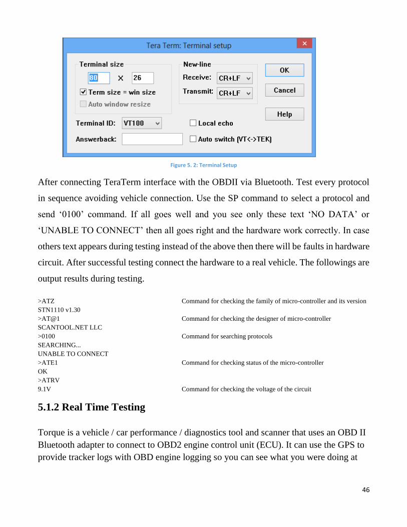
Figure 5. 2: Terminal Setup
After connecting TeraTerm interface with the OBDII via Bluetooth. Test every protocol
in sequence avoiding vehicle connection. Use the SP command to select a protocol and
send ‘0100’ command. If all goes well and you see only these text ‘NO DATA’ or
‘UNABLE TO CONNECT’ then all goes right and the hardware work correctly. In case
others text appears during testing instead of the above then there will be faults in hardware
circuit. After successful testing connect the hardware to a real vehicle. The followings are
output results during testing.
>ATZ Command for checking the family of micro-controller and its version
STN1110 v1.30
>AT@1 Command for checking the designer of micro-controller
SCANTOOL.NET LLC
>0100 Command for searching protocols
SEARCHING...
UNABLE TO CONNECT
>ATE1 Command for checking status of the micro-controller
OK
>ATRV
9.1V Command for checking the voltage of the circuit
5.1.2 Real Time Testing
Torque is a vehicle / car performance / diagnostics tool and scanner that uses an OBD II
Bluetooth adapter to connect to OBD2 engine control unit (ECU). It can use the GPS to
provide tracker logs with OBD engine logging so you can see what you were doing at

47
any point in real time. It can also show and reset a DTC fault codes and show you exact
location of faults.
To start with OBDII and Torque, First connect the OBDII with vehicle on one side and
with Torque on other side. Successful connection of torque with OBDII shown in the
following Figure 4.
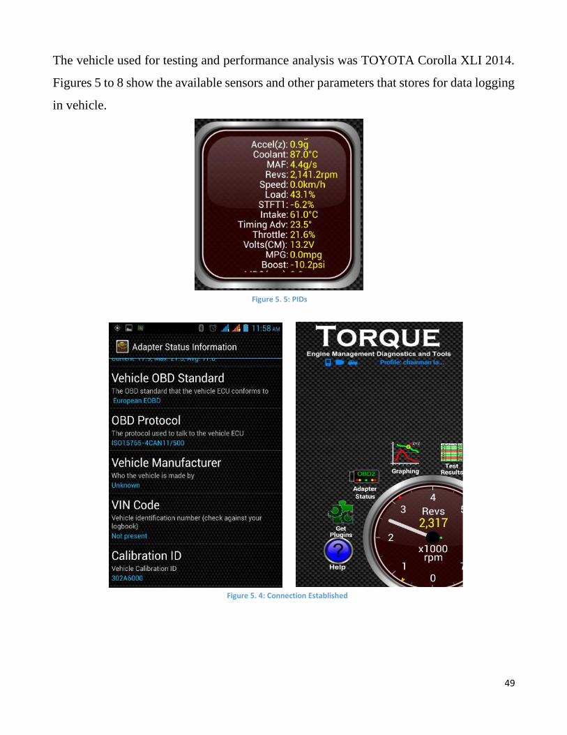
After establishing the connection of torque with communication device, the information
is then retrieving from the vehicle ECU. The adaptor status information also shows the
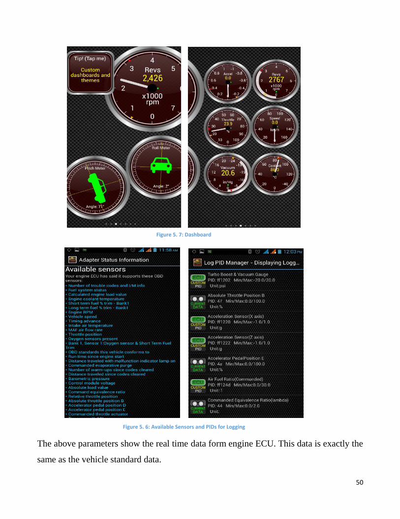
vehicle OBD standard, OBD protocol used by vehicle, calibration id and available sensor
etc. The OBDII port is capable of reading the following information from a vehicle:
a) Turbo Boost Pressure (PSI)
b) Fuel Economy (Real-Time/AVG/Trip)
c) Timing Position
d) Speed (MPH, KPH)
e) Engine RPM
f) Coolant Temperature
g) Throttle Position (in percent)
h) Injection Pulse width (IPW)
i) Air Intake Temperature
j) Mass Air Flow (g/sec)
Figure 5. 3: Successful connection of Torque
48
k) Throttle Position
l) Barometer
m) Battery Voltage
n) Engine Oil Temperature
o) Injection Control Pressure (ICP)
p) Transmission temperature
q) Load
49
The vehicle used for testing and performance analysis was TOYOTA Corolla XLI 2014.
Figures 5 to 8 show the available sensors and other parameters that stores for data logging
in vehicle.
Figure 5. 5: PIDs
Figure 5. 4: Connection Established
50
The above parameters show the real time data form engine ECU. This data is exactly the
same as the vehicle standard data.
Figure 1: Adapter Status information Main Menu Figure 5. 7: Dashboard
Figure 5. 6: Available Sensors and PIDs for Logging
51
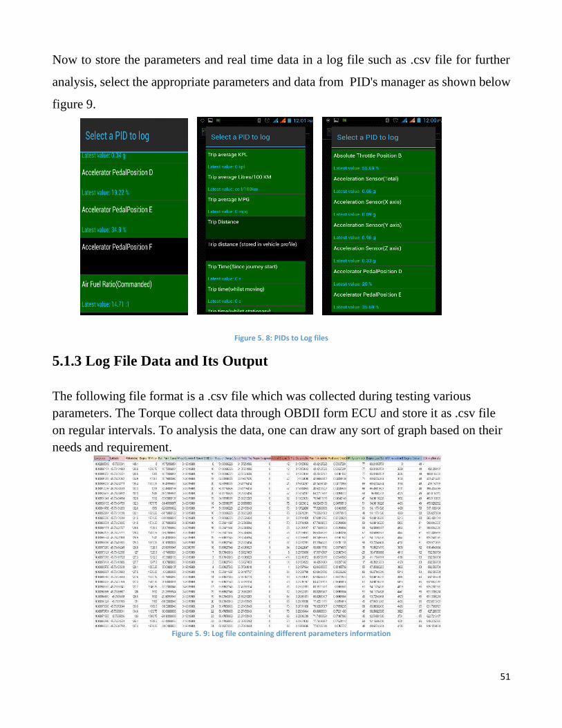
Now to store the parameters and real time data in a log file such as .csv file for further
analysis, select the appropriate parameters and data from PID's manager as shown below
figure 9.
Figure 5. 8: PIDs to Log files
5.1.3 Log File Data and Its Output
The following file format is a .csv file which was collected during testing various
parameters. The Torque collect data through OBDII form ECU and store it as .csv file
on regular intervals. To analysis the data, one can draw any sort of graph based on their
needs and requirement.
Figure 5. 9: Log file containing different parameters information
52
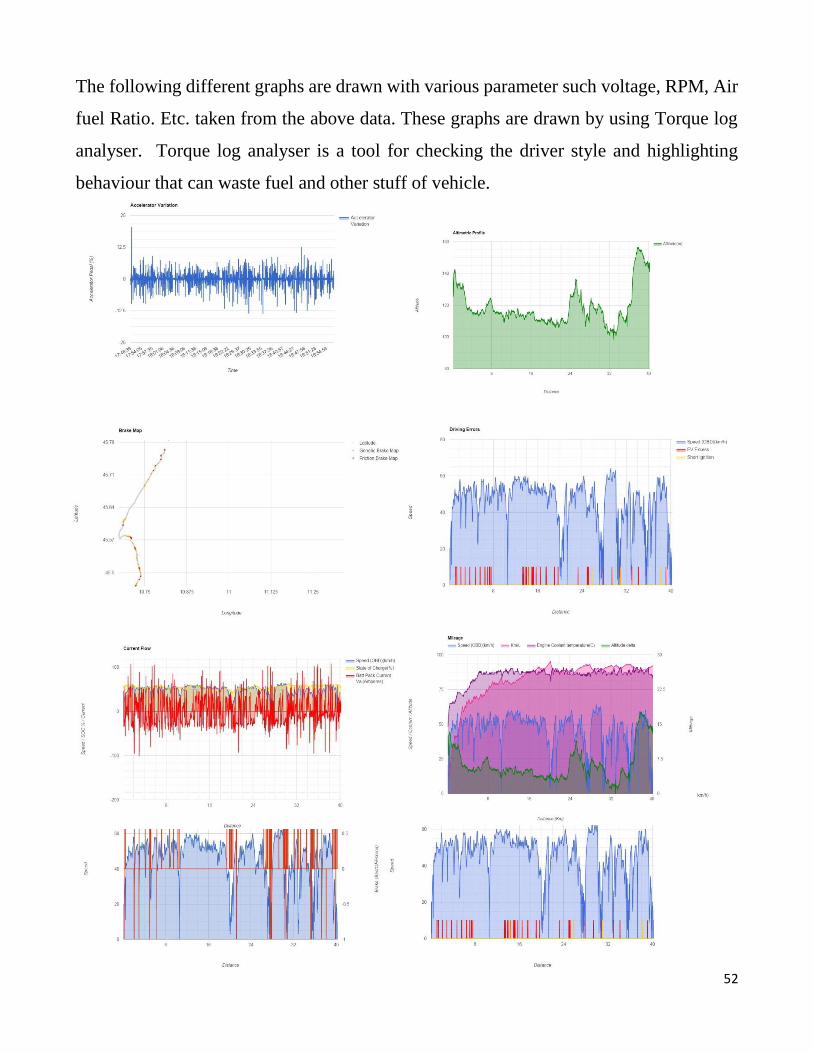
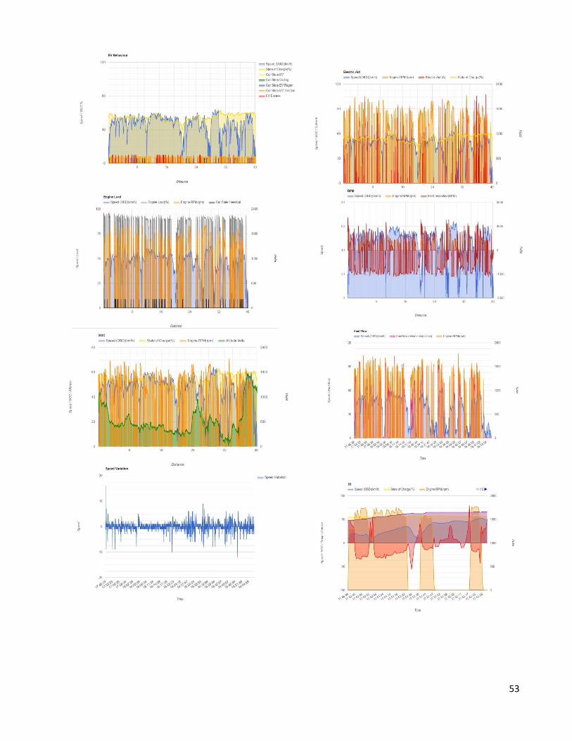
The following different graphs are drawn with various parameter such voltage, RPM, Air
fuel Ratio. Etc. taken from the above data. These graphs are drawn by using Torque log
analyser. Torque log analyser is a tool for checking the driver style and highlighting
behaviour that can waste fuel and other stuff of vehicle.
53
54
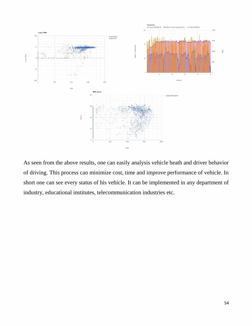
As seen from the above results, one can easily analysis vehicle heath and driver behavior
of driving. This process can minimize cost, time and improve performance of vehicle. In
short one can see every status of his vehicle. It can be implemented in any department of
industry, educational institutes, telecommunication industries etc.
55
Chapter 6
Application and Conclusion
6.1 Applications:
Potential Application of our proposed and developed work is: one can remotely monitor
vehicle health, check faults, emission detection problems, avoid the higher fuel
consumptions etc. Using this parameters individual or industries or groups can optimize
the expense of vehicles and faults can be predicted and notify the managers in time.
6.1.1 User Applications
Individual and Industrial Users can benefit from it in many ways. E.g. he can locate their
vehicle, monitor the vehicle performance and detect faults in any part of vehicle. To detect
the fault on time one can drive safely and prevent accidents. User can benefit from it by
checking his vehicle itself, thus reduce operation and mechanical costs.
6.1.2 Enterprise applications
Some Enterprise application may include Fleet tracking, monitoring fuel efficiency.
Through this device Enterprise can know the driving behavior of their drivers. Also they
can remotely diagnostic their vehicles in areas where vehicle repair service is not
available.
6.2 Conclusion
This project gives us the information about the technology used in vehicles for extracting
data through ECU from vehicle sensors. The extracted data is subsequently used for
vehicle management, monitoring and health performance optimization. It’s an exciting
area in the field of automotive engineering. This can enhance existing telemetry system.
56
It will be helpful in developing a commercial grade machinery performance optimization
system.
6.3 Recommendation
The remote examination of OBD information has been considered OBDIII or OBD X.
This concept implicates that using wireless techniques in the OBDII scan tool which is
directly connected to the ECU of vehicle should be equipped permanently. The real-time
information gets from ECU through OBDII scan tool is directly send to the database of
ERP System, where the data is automatically analyzed and diagnosed. This can handle a
large fleet of vehicles. Such system would be simple and convenient for both users and
enterprise fleet solution.
57
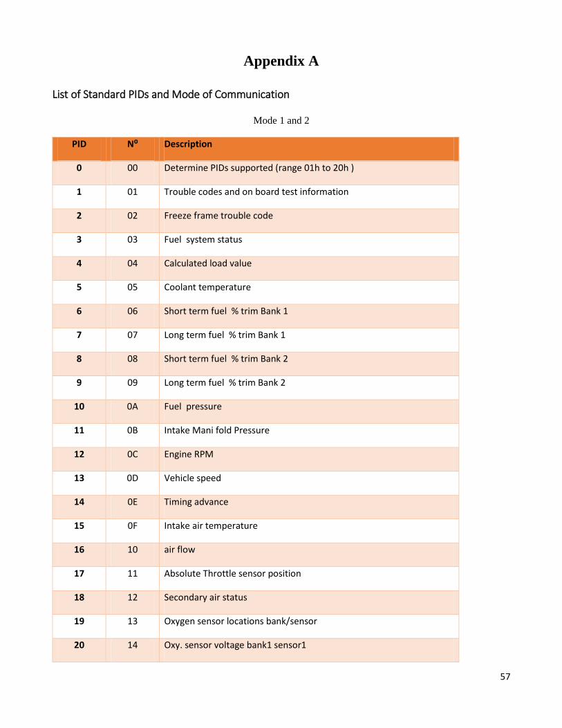
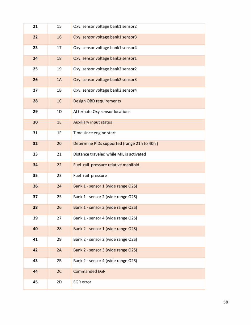
Appendix A
List of Standard PIDs and Mode of Communication
Mode 1 and 2
PID N⁰ Description
0 00 Determine PIDs supported (range 01h to 20h )
1 01 Trouble codes and on board test information
2 02 Freeze frame trouble code
3 03 Fuel system status
4 04 Calculated load value
5 05 Coolant temperature
6 06 Short term fuel % trim Bank 1
7 07 Long term fuel % trim Bank 1
8 08 Short term fuel % trim Bank 2
9 09 Long term fuel % trim Bank 2
10 0A Fuel pressure
11 0B Intake Mani fold Pressure
12 0C Engine RPM
13 0D Vehicle speed
14 0E Timing advance
15 0F Intake air temperature
16 10 air flow
17 11 Absolute Throttle sensor position
18 12 Secondary air status
19 13 Oxygen sensor locations bank/sensor
20 14 Oxy. sensor voltage bank1 sensor1
58
21 15 Oxy. sensor voltage bank1 sensor2
22 16 Oxy. sensor voltage bank1 sensor3
23 17 Oxy. sensor voltage bank1 sensor4
24 18 Oxy. sensor voltage bank2 sensor1
25 19 Oxy. sensor voltage bank2 sensor2
26 1A Oxy. sensor voltage bank2 sensor3
27 1B Oxy. sensor voltage bank2 sensor4
28 1C Design OBD requirements
29 1D Al ternate Oxy sensor locations
30 1E Auxiliary input status
31 1F Time since engine start
32 20 Determine PIDs supported (range 21h to 40h )
33 21 Distance traveled while MIL is activated
34 22 Fuel rail pressure relative manifold
35 23 Fuel rail pressure
36 24 Bank 1 - sensor 1 (wide range O2S)
37 25 Bank 1 - sensor 2 (wide range O2S)
38 26 Bank 1 - sensor 3 (wide range O2S)
39 27 Bank 1 - sensor 4 (wide range O2S)
40 28 Bank 2 - sensor 1 (wide range O2S)
41 29 Bank 2 - sensor 2 (wide range O2S)
42 2A Bank 2 - sensor 3 (wide range O2S)
43 2B Bank 2 - sensor 4 (wide range O2S)
44 2C Commanded EGR
45 2D EGR error
59
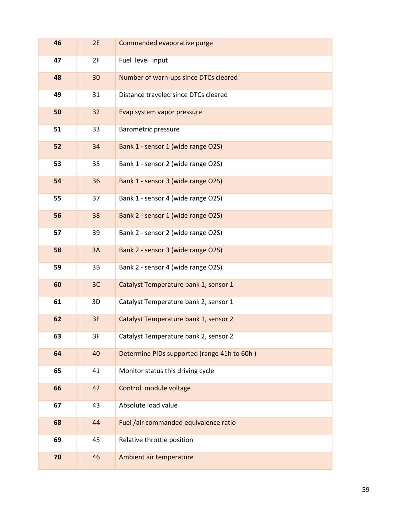
46 2E Commanded evaporative purge
47 2F Fuel level input
48 30 Number of warn-ups since DTCs cleared
49 31 Distance traveled since DTCs cleared
50 32 Evap system vapor pressure
51 33 Barometric pressure
52 34 Bank 1 - sensor 1 (wide range O2S)
53 35 Bank 1 - sensor 2 (wide range O2S)
54 36 Bank 1 - sensor 3 (wide range O2S)
55 37 Bank 1 - sensor 4 (wide range O2S)
56 38 Bank 2 - sensor 1 (wide range O2S)
57 39 Bank 2 - sensor 2 (wide range O2S)
58 3A Bank 2 - sensor 3 (wide range O2S)
59 3B Bank 2 - sensor 4 (wide range O2S)
60 3C Catalyst Temperature bank 1, sensor 1
61 3D Catalyst Temperature bank 2, sensor 1
62 3E Catalyst Temperature bank 1, sensor 2
63 3F Catalyst Temperature bank 2, sensor 2
64 40 Determine PIDs supported (range 41h to 60h )
65 41 Monitor status this driving cycle
66 42 Control module voltage
67 43 Absolute load value
68 44 Fuel /air commanded equivalence ratio
69 45 Relative throttle position
70 46 Ambient air temperature
60
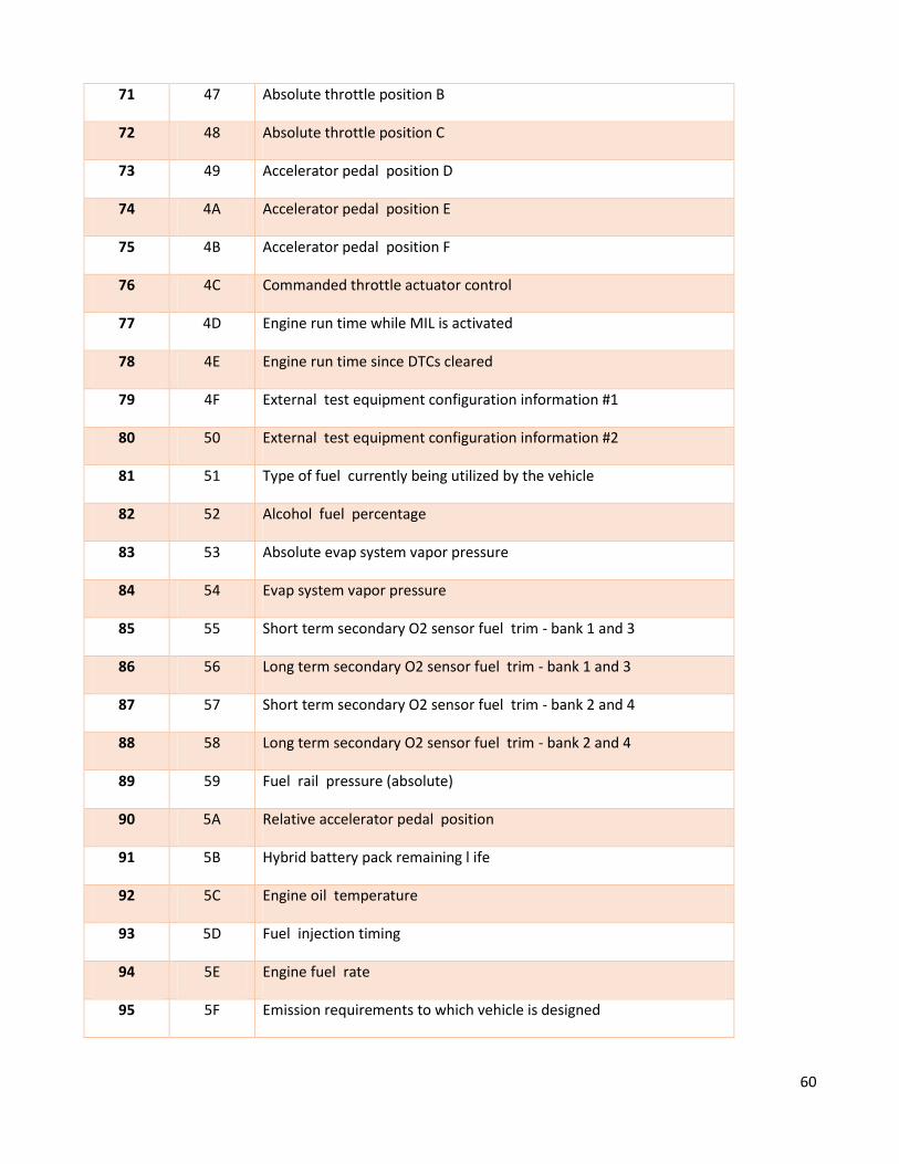
71 47 Absolute throttle position B
72 48 Absolute throttle position C
73 49 Accelerator pedal position D
74 4A Accelerator pedal position E
75 4B Accelerator pedal position F
76 4C Commanded throttle actuator control
77 4D Engine run time while MIL is activated
78 4E Engine run time since DTCs cleared
79 4F External test equipment configuration information #1
80 50 External test equipment configuration information #2
81 51 Type of fuel currently being utilized by the vehicle
82 52 Alcohol fuel percentage
83 53 Absolute evap system vapor pressure
84 54 Evap system vapor pressure
85 55 Short term secondary O2 sensor fuel trim - bank 1 and 3
86 56 Long term secondary O2 sensor fuel trim - bank 1 and 3
87 57 Short term secondary O2 sensor fuel trim - bank 2 and 4
88 58 Long term secondary O2 sensor fuel trim - bank 2 and 4
89 59 Fuel rail pressure (absolute)
90 5A Relative accelerator pedal position
91 5B Hybrid battery pack remaining l ife
92 5C Engine oil temperature
93 5D Fuel injection timing
94 5E Engine fuel rate
95 5F Emission requirements to which vehicle is designed
61
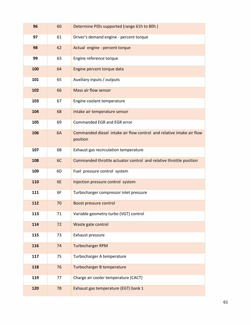
96 60 Determine PIDs supported (range 61h to 80h )
97 61 Driver's demand engine - percent torque
98 62 Actual engine - percent torque
99 63 Engine reference torque
100 64 Engine percent torque data
101 65 Auxiliary inputs / outputs
102 66 Mass air flow sensor
103 67 Engine coolant temperature
104 68 Intake air temperature sensor
105 69 Commanded EGR and EGR error
106 6A Commanded diesel intake air flow control and relative intake air flow
position
107 6B Exhaust gas recirculation temperature
108 6C Commanded throttle actuator control and relative throttle position
109 6D Fuel pressure control system
110 6E Injection pressure control system
111 6F Turbocharger compressor inlet pressure
112 70 Boost pressure control
113 71 Variable geometry turbo (VGT) control
114 72 Waste gate control
115 73 Exhaust pressure
116 74 Turbocharger RPM
117 75 Turbocharger A temperature
118 76 Turbocharger B temperature
119 77 Charge air cooler temperature (CACT)
120 78 Exhaust gas temperature (EGT) bank 1
62
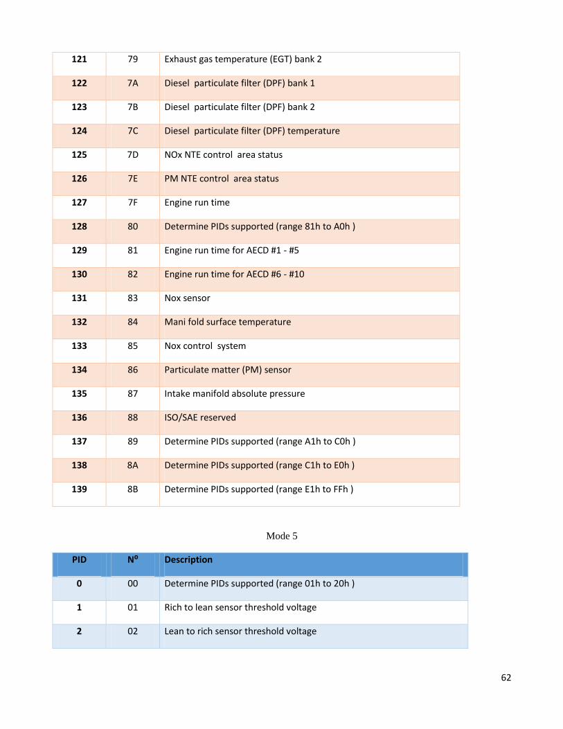
121 79 Exhaust gas temperature (EGT) bank 2
122 7A Diesel particulate filter (DPF) bank 1
123 7B Diesel particulate filter (DPF) bank 2
124 7C Diesel particulate filter (DPF) temperature
125 7D NOx NTE control area status
126 7E PM NTE control area status
127 7F Engine run time
128 80 Determine PIDs supported (range 81h to A0h )
129 81 Engine run time for AECD #1 - #5
130 82 Engine run time for AECD #6 - #10
131 83 Nox sensor
132 84 Mani fold surface temperature
133 85 Nox control system
134 86 Particulate matter (PM) sensor
135 87 Intake manifold absolute pressure
136 88 ISO/SAE reserved
137 89 Determine PIDs supported (range A1h to C0h )
138 8A Determine PIDs supported (range C1h to E0h )
139 8B Determine PIDs supported (range E1h to FFh )
Mode 5
PID N⁰ Description
0 00 Determine PIDs supported (range 01h to 20h )
1 01 Rich to lean sensor threshold voltage
2 02 Lean to rich sensor threshold voltage
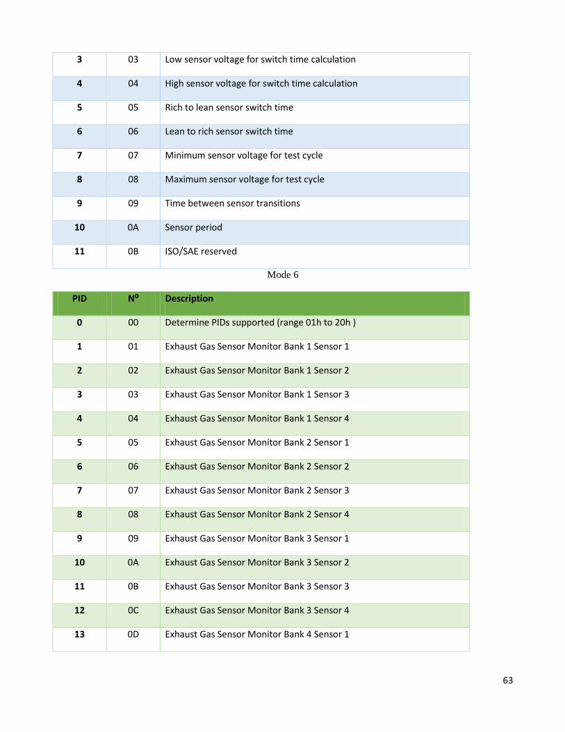
63
3 03 Low sensor voltage for switch time calculation
4 04 High sensor voltage for switch time calculation
5 05 Rich to lean sensor switch time
6 06 Lean to rich sensor switch time
7 07 Minimum sensor voltage for test cycle
8 08 Maximum sensor voltage for test cycle
9 09 Time between sensor transitions
10 0A Sensor period
11 0B ISO/SAE reserved
Mode 6
PID N⁰ Description
0 00 Determine PIDs supported (range 01h to 20h )
1 01 Exhaust Gas Sensor Monitor Bank 1 Sensor 1
2 02 Exhaust Gas Sensor Monitor Bank 1 Sensor 2
3 03 Exhaust Gas Sensor Monitor Bank 1 Sensor 3
4 04 Exhaust Gas Sensor Monitor Bank 1 Sensor 4
5 05 Exhaust Gas Sensor Monitor Bank 2 Sensor 1
6 06 Exhaust Gas Sensor Monitor Bank 2 Sensor 2
7 07 Exhaust Gas Sensor Monitor Bank 2 Sensor 3
8 08 Exhaust Gas Sensor Monitor Bank 2 Sensor 4
9 09 Exhaust Gas Sensor Monitor Bank 3 Sensor 1
10 0A Exhaust Gas Sensor Monitor Bank 3 Sensor 2
11 0B Exhaust Gas Sensor Monitor Bank 3 Sensor 3
12 0C Exhaust Gas Sensor Monitor Bank 3 Sensor 4
13 0D Exhaust Gas Sensor Monitor Bank 4 Sensor 1
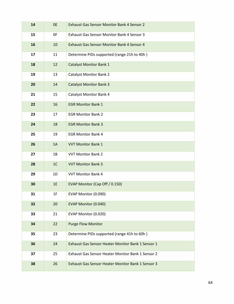
64
14 0E Exhaust Gas Sensor Monitor Bank 4 Sensor 2
15 0F Exhaust Gas Sensor Monitor Bank 4 Sensor 3
16 10 Exhaust Gas Sensor Monitor Bank 4 Sensor 4
17 11 Determine PIDs supported (range 21h to 40h )
18 12 Catalyst Monitor Bank 1
19 13 Catalyst Monitor Bank 2
20 14 Catalyst Monitor Bank 3
21 15 Catalyst Monitor Bank 4
22 16 EGR Monitor Bank 1
23 17 EGR Monitor Bank 2
24 18 EGR Monitor Bank 3
25 19 EGR Monitor Bank 4
26 1A VVT Monitor Bank 1
27 1B VVT Monitor Bank 2
28 1C VVT Monitor Bank 3
29 1D VVT Monitor Bank 4
30 1E EVAP Monitor (Cap Off / 0.150)
31 1F EVAP Monitor (0.090)
32 20 EVAP Monitor (0.040)
33 21 EVAP Monitor (0.020)
34 22 Purge Flow Monitor
35 23 Determine PIDs supported (range 41h to 60h )
36 24 Exhaust Gas Sensor Heater Monitor Bank 1 Sensor 1
37 25 Exhaust Gas Sensor Heater Monitor Bank 1 Sensor 2
38 26 Exhaust Gas Sensor Heater Monitor Bank 1 Sensor 3
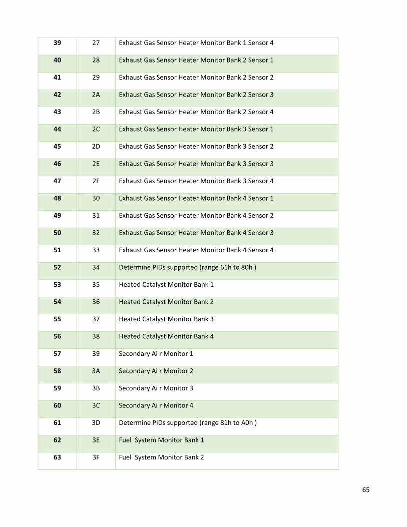
65
39 27 Exhaust Gas Sensor Heater Monitor Bank 1 Sensor 4
40 28 Exhaust Gas Sensor Heater Monitor Bank 2 Sensor 1
41 29 Exhaust Gas Sensor Heater Monitor Bank 2 Sensor 2
42 2A Exhaust Gas Sensor Heater Monitor Bank 2 Sensor 3
43 2B Exhaust Gas Sensor Heater Monitor Bank 2 Sensor 4
44 2C Exhaust Gas Sensor Heater Monitor Bank 3 Sensor 1
45 2D Exhaust Gas Sensor Heater Monitor Bank 3 Sensor 2
46 2E Exhaust Gas Sensor Heater Monitor Bank 3 Sensor 3
47 2F Exhaust Gas Sensor Heater Monitor Bank 3 Sensor 4
48 30 Exhaust Gas Sensor Heater Monitor Bank 4 Sensor 1
49 31 Exhaust Gas Sensor Heater Monitor Bank 4 Sensor 2
50 32 Exhaust Gas Sensor Heater Monitor Bank 4 Sensor 3
51 33 Exhaust Gas Sensor Heater Monitor Bank 4 Sensor 4
52 34 Determine PIDs supported (range 61h to 80h )
53 35 Heated Catalyst Monitor Bank 1
54 36 Heated Catalyst Monitor Bank 2
55 37 Heated Catalyst Monitor Bank 3
56 38 Heated Catalyst Monitor Bank 4
57 39 Secondary Ai r Monitor 1
58 3A Secondary Ai r Monitor 2
59 3B Secondary Ai r Monitor 3
60 3C Secondary Ai r Monitor 4
61 3D Determine PIDs supported (range 81h to A0h )
62 3E Fuel System Monitor Bank 1
63 3F Fuel System Monitor Bank 2
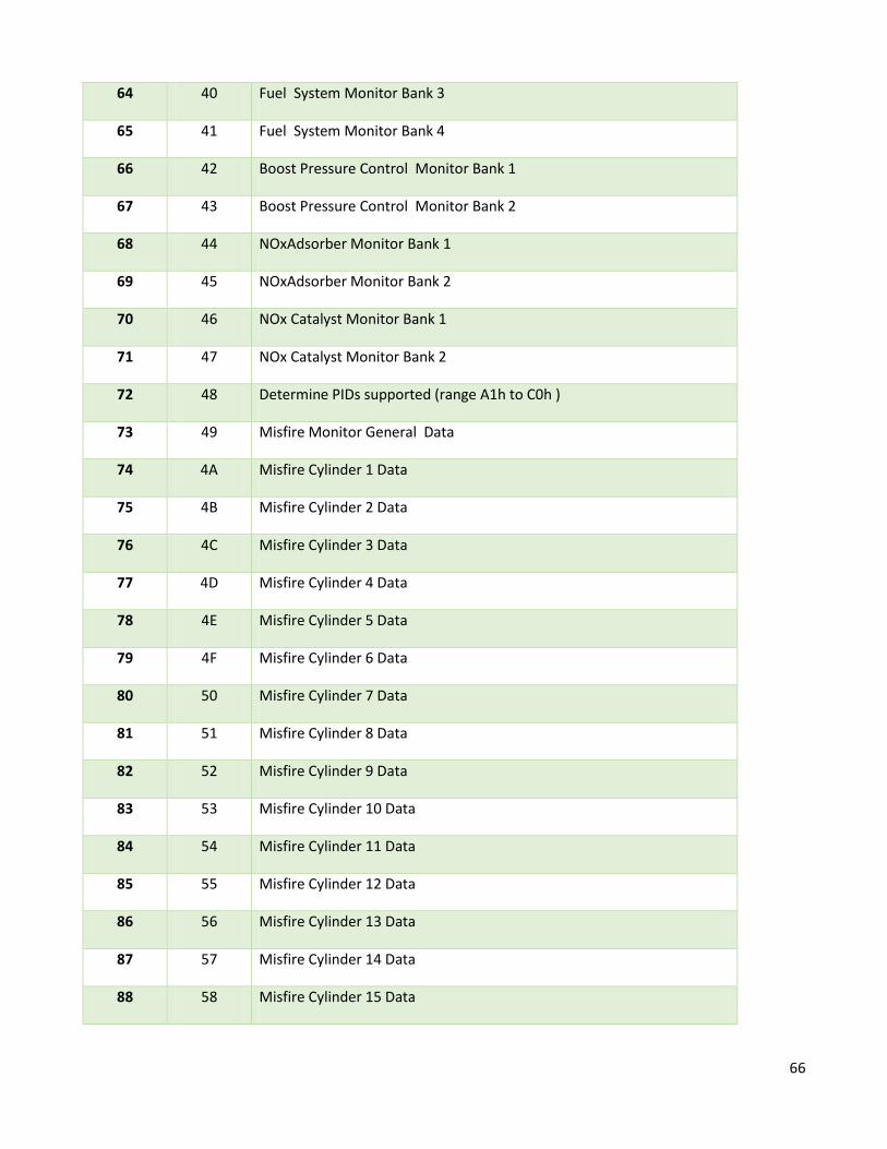
66
64 40 Fuel System Monitor Bank 3
65 41 Fuel System Monitor Bank 4
66 42 Boost Pressure Control Monitor Bank 1
67 43 Boost Pressure Control Monitor Bank 2
68 44 NOxAdsorber Monitor Bank 1
69 45 NOxAdsorber Monitor Bank 2
70 46 NOx Catalyst Monitor Bank 1
71 47 NOx Catalyst Monitor Bank 2
72 48 Determine PIDs supported (range A1h to C0h )
73 49 Misfire Monitor General Data
74 4A Misfire Cylinder 1 Data
75 4B Misfire Cylinder 2 Data
76 4C Misfire Cylinder 3 Data
77 4D Misfire Cylinder 4 Data
78 4E Misfire Cylinder 5 Data
79 4F Misfire Cylinder 6 Data
80 50 Misfire Cylinder 7 Data
81 51 Misfire Cylinder 8 Data
82 52 Misfire Cylinder 9 Data
83 53 Misfire Cylinder 10 Data
84 54 Misfire Cylinder 11 Data
85 55 Misfire Cylinder 12 Data
86 56 Misfire Cylinder 13 Data
87 57 Misfire Cylinder 14 Data
88 58 Misfire Cylinder 15 Data

67
89 59 Misfire Cylinder 16 Data
90 5A PM Filter Monitor Bank 1
91 5B PM Filter Monitor Bank 2
92 5C Determine PIDs supported (range C1h to E0h )
93 5D Determine PIDs supported (range E1h to FFh )
94 5E Manufacturer specific
Mode 9
PID N⁰ Description
0 00 Determine PIDs supported (range 01h to 20h )
1 01 MessageCount VIN
2 02 Vehicle Identification Number
3 03 MessageCount CALID
4 04 Calibration Identifications
5 05 MessageCount CVN
6 06 Calibration Verification Numbers
7 07 MessageCount IPT
8 08 In-use Performance Tracking
9 09 MessageCount ECU name
10 0A ECU name
11 0B In-use Performance Tracking
12-255 0C-FF ISO/SAE reserved
68
Appendix B
Steps for Installing OpenERP in Ubuntu
Following steps are required for installing OpenERP in Ubuntu:
Step 1:
Make sure your server has all the latest versions by doing an update:
sudo apt-get update
sudo apt-get dist-upgrade
Step 2:
Create the OpenERP user that will own and run the application /opt/openerp directory is
created automatically by the following command and here the OpenERP server code will
reside.
sudoadduser --system --home=/opt/openerp --group openerp
To go in openERP’s home directory: /opt/openerp, use command:
sudosu - openerp -s /bin/bash
You can leave the openerpuser areas shell by typing "exit".
Step 3:
Install and configure the database server, PostgreSQL
sudo apt-get install postgresql
Then configure the OpenERP user on PostgreSQL:
69
To have the necessary privileges to configure the database, change to the postgres user by
using the command:
sudosu - postgres
Now create a new database user so that OpenERP has access rights to connect to
PostgreSQL and to create and drop databases.
createuser --createdb --username postgres --no-
createrole --no-superuser --pwpromptopenerp
Enter password for new role: ********
Enter it again: ********
Then exit from postgres user account by using "exit" command.
Step 4:
Install the necessary Python libraries for the server
sudo apt-get install python-dateutil python-docutils python-
feedparser python-gdata \
python-jinja2 python-ldap python-libxslt1 python-lxml
python-mako python-mock python-openid \
python-psycopg2 python-psutil python-pybabel python-pychart
python-pydot python-pyparsing \
python-reportlab python-simplejson python-tz python-
unittest2 python-vatnumber python-vobject \
python-webdav python-werkzeug python-xlwt python-yaml
python-zsi
By doing this, all the dependencies for installing OpenERP 7.0 will be satisfied.
70
Step 5:
Install the OpenERP server
Get the latest version of OpenERP in your home directory using following command.
wget
http://nightly.openerp.com/7.0/nightly/src/openerp-7.0-
latest.tar.gz
To extract the tarball in the /opt/openerp/. cd to the /opt/openerp/
cd /opt/openerp/
sudo tar xvf ~/openerp-7.0-latest.tar.gz
Now change the ownership of all the files to the OpenERP user and group by using
command:
sudochown -R openerp: *
sudocp -a openerp-7.0 server
Step 6:
Configuring the OpenERP application
The following commands make the file owned and writeable only by the openerp user and
group and only readable by openerp and root.
sudocp /opt/openerp/server/install/openerp-server.conf
/etc/
sudochownopenerp: /etc/openerp-server.conf
sudochmod 640 /etc/openerp-server.conf
71
Change line db_password = False to the same password you used back in step 3 by using
the command:
sudonano /etc/openerp-server.conf
logfile = /var/log/openerp/openerp-server.log
Now we can start the server just to check if it actually runs.
sudosu - openerp -s /bin/bash
/opt/openerp/server/openerp-server
If you end up with a few lines eventually saying OpenERP is running and waiting for
connections then you are all set. Enter CTL+C to stop the server and then exit to leave the
openerp user account and go back to your own shell. To make it executable and owned by
root use commands:
sudochmod 755 /etc/init.d/openerp-server
sudochown root: /etc/init.d/openerp-server
Step 7:
Now we need to create a directory so that the server has somewhere to log and we must
make it writeable by the openerp user:
sudomkdir /var/log/openerp
sudochownopenerp:root /var/log/openerp
Step 8:
Testing the server. To start the OpenERP server type:
sudo /etc/init.d/openerp-server start
To stop the OpenERP server type:
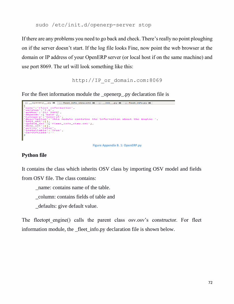
72
sudo /etc/init.d/openerp-server stop
If there are any problems you need to go back and check. There’s really no point ploughing
on if the server doesn’t start. If the log file looks Fine, now point the web browser at the
domain or IP address of your OpenERP server (or local host if on the same machine) and
use port 8069. The url will look something like this:
http://IP_or_domain.com:8069
For the fleet information module the _openerp_.py declaration file is
Figure Appendix B. 1: OpenERP.py
Python file
It contains the class which inherits OSV class by importing OSV model and fields
from OSV file. The class contains:
_name: contains name of the table.
_column: contains fields of table and
_defaults: give default value.
The fleetopt_engine() calls the parent class osv.osv’s constructor. For fleet
information module, the _fleet_info.py declaration file is shown below.
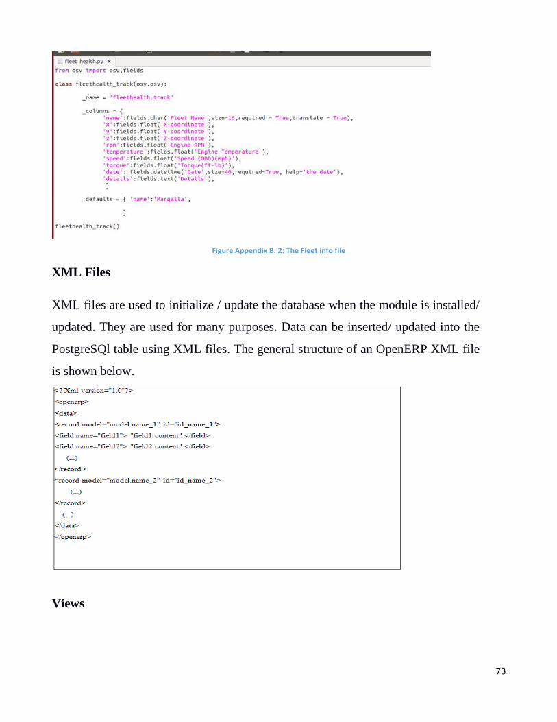
73
Figure Appendix B. 2: The Fleet info file
XML Files
XML files are used to initialize / update the database when the module is installed/
updated. They are used for many purposes. Data can be inserted/ updated into the
PostgreSQl table using XML files. The general structure of an OpenERP XML file
is shown below.
Views

74
Views are a way to represent objects on the client side. They indicate the client how
to layout the data on the screen coming from the objects.
There are three types of views.
Form view
Tree view
Search view
Form view:
It is used when the user wants to edit or add the information. By default each field is
preceded by a label, with its name. The following code displays the form view of module.
Tree View
Tree view is aslo called list view. We can specify columns which we want to add in
the list.
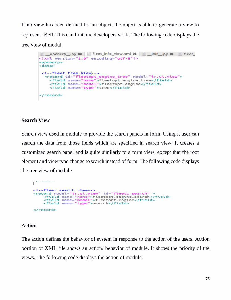
75
If no view has been defined for an object, the object is able to generate a view to
represent itself. This can limit the developers work. The following code displays the
tree view of modul.
Search View
Search view used in module to provide the search panels in form. Using it user can
search the data from those fields which are specified in search view. It creates a
customized search panel and is quite similarly to a form view, except that the root
element and view type change to search instead of form. The following code displays
the tree view of module.
Action
The action defines the behavior of system in response to the action of the users. Action
portion of XML file shows an action/ behavior of module. It shows the priority of the
views. The following code displays the action of module.

76
Menu
In OpenERP, this element represents a menu structure. We can trigger an action created
above by clicking on the menu. The following code displays the menu of module.
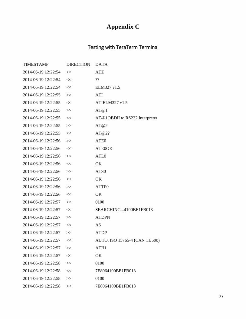
77
Appendix C
Testing with TeraTerm Terminal
TIMESTAMP DIRECTION DATA
2014-06-19 12:22:54 >> ATZ
2014-06-19 12:22:54 << ??
2014-06-19 12:22:54 << ELM327 v1.5
2014-06-19 12:22:55 >> ATI
2014-06-19 12:22:55 << ATIELM327 v1.5
2014-06-19 12:22:55 >> AT@1
2014-06-19 12:22:55 << AT@1OBDII to RS232 Interpreter
2014-06-19 12:22:55 >> AT@2
2014-06-19 12:22:55 << AT@2?
2014-06-19 12:22:56 >> ATE0
2014-06-19 12:22:56 << ATE0OK
2014-06-19 12:22:56 >> ATL0
2014-06-19 12:22:56 << OK
2014-06-19 12:22:56 >> ATS0
2014-06-19 12:22:56 << OK
2014-06-19 12:22:56 >> ATTP0
2014-06-19 12:22:56 << OK
2014-06-19 12:22:57 >> 0100
2014-06-19 12:22:57 << SEARCHING...4100BE1FB013
2014-06-19 12:22:57 >> ATDPN
2014-06-19 12:22:57 << A6
2014-06-19 12:22:57 >> ATDP
2014-06-19 12:22:57 << AUTO, ISO 15765-4 (CAN 11/500)
2014-06-19 12:22:57 >> ATH1
2014-06-19 12:22:57 << OK
2014-06-19 12:22:58 >> 0100
2014-06-19 12:22:58 << 7E8064100BE1FB013
2014-06-19 12:22:58 >> 0100
2014-06-19 12:22:58 << 7E8064100BE1FB013
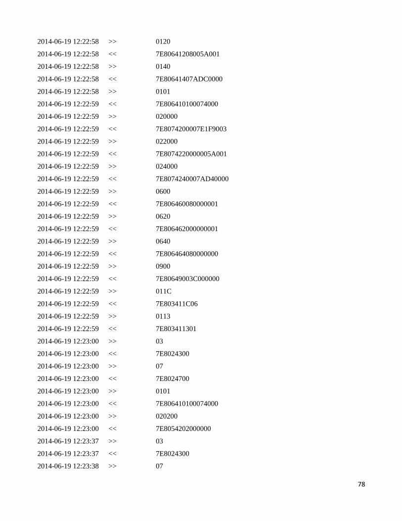
78
2014-06-19 12:22:58 >> 0120
2014-06-19 12:22:58 << 7E80641208005A001
2014-06-19 12:22:58 >> 0140
2014-06-19 12:22:58 << 7E80641407ADC0000
2014-06-19 12:22:58 >> 0101
2014-06-19 12:22:59 << 7E806410100074000
2014-06-19 12:22:59 >> 020000
2014-06-19 12:22:59 << 7E8074200007E1F9003
2014-06-19 12:22:59 >> 022000
2014-06-19 12:22:59 << 7E8074220000005A001
2014-06-19 12:22:59 >> 024000
2014-06-19 12:22:59 << 7E8074240007AD40000
2014-06-19 12:22:59 >> 0600
2014-06-19 12:22:59 << 7E806460080000001
2014-06-19 12:22:59 >> 0620
2014-06-19 12:22:59 << 7E806462000000001
2014-06-19 12:22:59 >> 0640
2014-06-19 12:22:59 << 7E806464080000000
2014-06-19 12:22:59 >> 0900
2014-06-19 12:22:59 << 7E80649003C000000
2014-06-19 12:22:59 >> 011C
2014-06-19 12:22:59 << 7E803411C06
2014-06-19 12:22:59 >> 0113
2014-06-19 12:22:59 << 7E803411301
2014-06-19 12:23:00 >> 03
2014-06-19 12:23:00 << 7E8024300
2014-06-19 12:23:00 >> 07
2014-06-19 12:23:00 << 7E8024700
2014-06-19 12:23:00 >> 0101
2014-06-19 12:23:00 << 7E806410100074000
2014-06-19 12:23:00 >> 020200
2014-06-19 12:23:00 << 7E8054202000000
2014-06-19 12:23:37 >> 03
2014-06-19 12:23:37 << 7E8024300
2014-06-19 12:23:38 >> 07
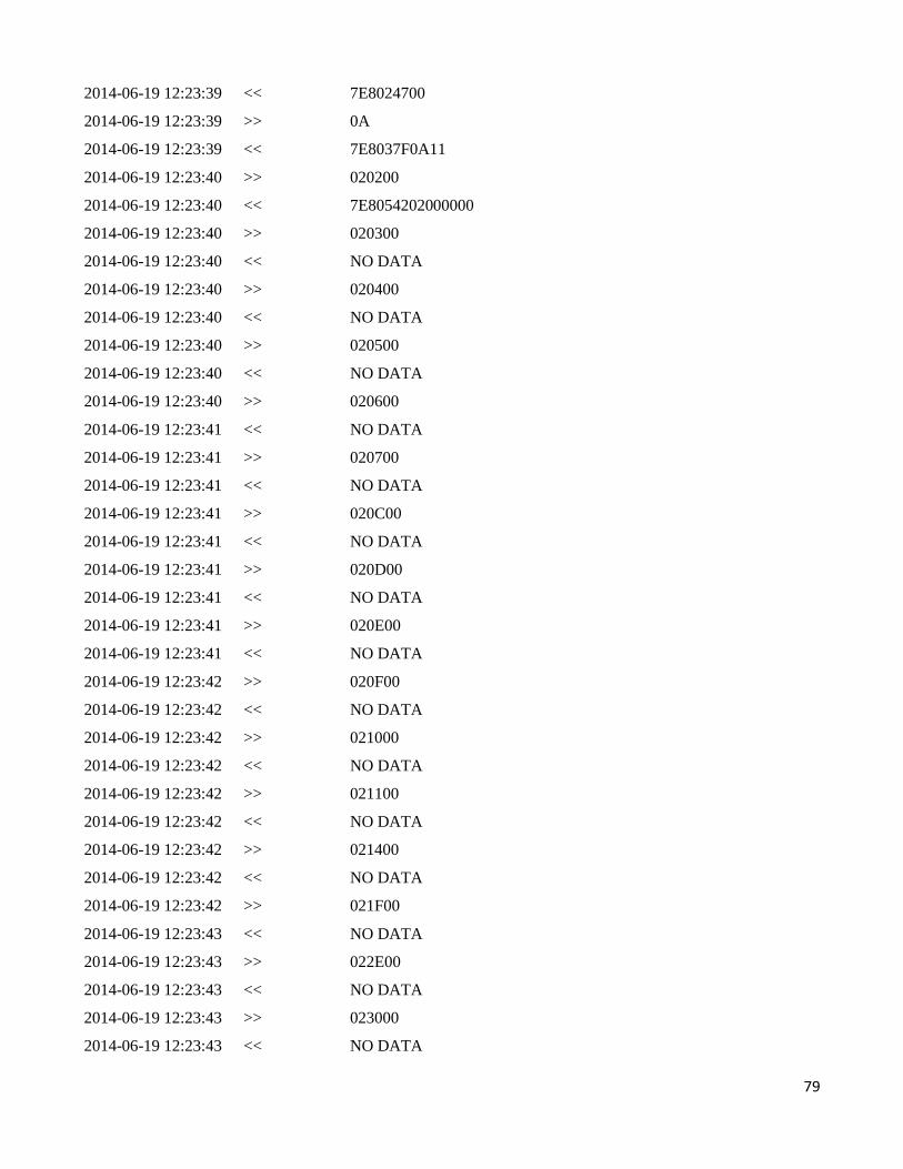
79
2014-06-19 12:23:39 << 7E8024700
2014-06-19 12:23:39 >> 0A
2014-06-19 12:23:39 << 7E8037F0A11
2014-06-19 12:23:40 >> 020200
2014-06-19 12:23:40 << 7E8054202000000
2014-06-19 12:23:40 >> 020300
2014-06-19 12:23:40 << NO DATA
2014-06-19 12:23:40 >> 020400
2014-06-19 12:23:40 << NO DATA
2014-06-19 12:23:40 >> 020500
2014-06-19 12:23:40 << NO DATA
2014-06-19 12:23:40 >> 020600
2014-06-19 12:23:41 << NO DATA
2014-06-19 12:23:41 >> 020700
2014-06-19 12:23:41 << NO DATA
2014-06-19 12:23:41 >> 020C00
2014-06-19 12:23:41 << NO DATA
2014-06-19 12:23:41 >> 020D00
2014-06-19 12:23:41 << NO DATA
2014-06-19 12:23:41 >> 020E00
2014-06-19 12:23:41 << NO DATA
2014-06-19 12:23:42 >> 020F00
2014-06-19 12:23:42 << NO DATA
2014-06-19 12:23:42 >> 021000
2014-06-19 12:23:42 << NO DATA
2014-06-19 12:23:42 >> 021100
2014-06-19 12:23:42 << NO DATA
2014-06-19 12:23:42 >> 021400
2014-06-19 12:23:42 << NO DATA
2014-06-19 12:23:42 >> 021F00
2014-06-19 12:23:43 << NO DATA
2014-06-19 12:23:43 >> 022E00
2014-06-19 12:23:43 << NO DATA
2014-06-19 12:23:43 >> 023000
2014-06-19 12:23:43 << NO DATA
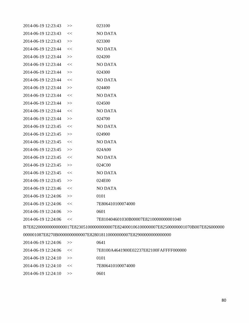
80
2014-06-19 12:23:43 >> 023100
2014-06-19 12:23:43 << NO DATA
2014-06-19 12:23:43 >> 023300
2014-06-19 12:23:44 << NO DATA
2014-06-19 12:23:44 >> 024200
2014-06-19 12:23:44 << NO DATA
2014-06-19 12:23:44 >> 024300
2014-06-19 12:23:44 << NO DATA
2014-06-19 12:23:44 >> 024400
2014-06-19 12:23:44 << NO DATA
2014-06-19 12:23:44 >> 024500
2014-06-19 12:23:44 << NO DATA
2014-06-19 12:23:44 >> 024700
2014-06-19 12:23:45 << NO DATA
2014-06-19 12:23:45 >> 024900
2014-06-19 12:23:45 << NO DATA
2014-06-19 12:23:45 >> 024A00
2014-06-19 12:23:45 << NO DATA
2014-06-19 12:23:45 >> 024C00
2014-06-19 12:23:45 << NO DATA
2014-06-19 12:23:45 >> 024E00
2014-06-19 12:23:46 << NO DATA
2014-06-19 12:24:06 >> 0101
2014-06-19 12:24:06 << 7E806410100074000
2014-06-19 12:24:06 >> 0601
2014-06-19 12:24:06 << 7E810404601030B00007E8210000000001040
B7E822000000000000017E823051000000000007E824000106100000007E82500000001070B007E826000000
000001087E8270B0000000000007E828018110000000007E82900000000000000
2014-06-19 12:24:06 >> 0641
2014-06-19 12:24:06 << 7E8100A4641900E02237E82100FAFFFF000000
2014-06-19 12:24:10 >> 0101
2014-06-19 12:24:10 << 7E806410100074000
2014-06-19 12:24:10 >> 0601
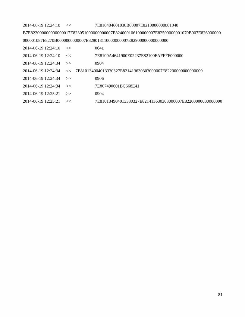
81
2014-06-19 12:24:10 << 7E810404601030B00007E8210000000001040
B7E822000000000000017E823051000000000007E824000106100000007E82500000001070B007E826000000
000001087E8270B0000000000007E828018110000000007E82900000000000000
2014-06-19 12:24:10 >> 0641
2014-06-19 12:24:10 << 7E8100A4641900E02237E82100FAFFFF000000
2014-06-19 12:24:34 >> 0904
2014-06-19 12:24:34 << 7E810134904013330327E821413630303000007E82200000000000000
2014-06-19 12:24:34 >> 0906
2014-06-19 12:24:34 << 7E807490601BC668E41
2014-06-19 12:25:21 >> 0904
2014-06-19 12:25:21 << 7E810134904013330327E821413630303000007E82200000000000000
82
Appendix D
OBDII
In the 1970’s and later in 1980’s manufacturers’ underway of using electronic means to
control engine functionality and detect engine problems. It was the primarily aim to meet
EPA emission standards. Over the years OBDII system has become more developed.
OBDII a new standard was presented in 1990 which provide almost all engine control and
also monitors parts of the chassis, body and accessory devices, as well as the diagnostic
control network of the vehicle.
For avoiding smog problems in the LA Basin, the California state started demanding an
emission control systems on 66’s model cars. Smog problem in the LA basin, the State of
California started demand in emission control systems on 1966 model cars. Afterwards
the federal government in 1968 extended these controls countrywide. Congress approved
the Clean Air Act in 1970 and established the Environmental Protection Agency (EPA).
Thus a sequence of graduated emission standards and requirements for optimization and
maintenance of vehicles health had started for extended period of time. To come upon
these standards, manufactures turned into electronically controlled fuel feed and ignition
systems. Different sensors available in the vehicle measured engine performance and
adjusted the systems to provide minimum pollution.
In the beginning each manufacturer had their own framework for extracting data. In 1988,
the Society of Automotive Engineers (SAE) set a standard connector plug and set of
diagnostic test signals. The standard connector plug consists of sixteen pin and in which
five are data pins. OBDII is an extended set of standards and practices developed by SAE
and adopted by the EPA and California Air Resources Board (CARB) for implementation
by 1 January 1996.
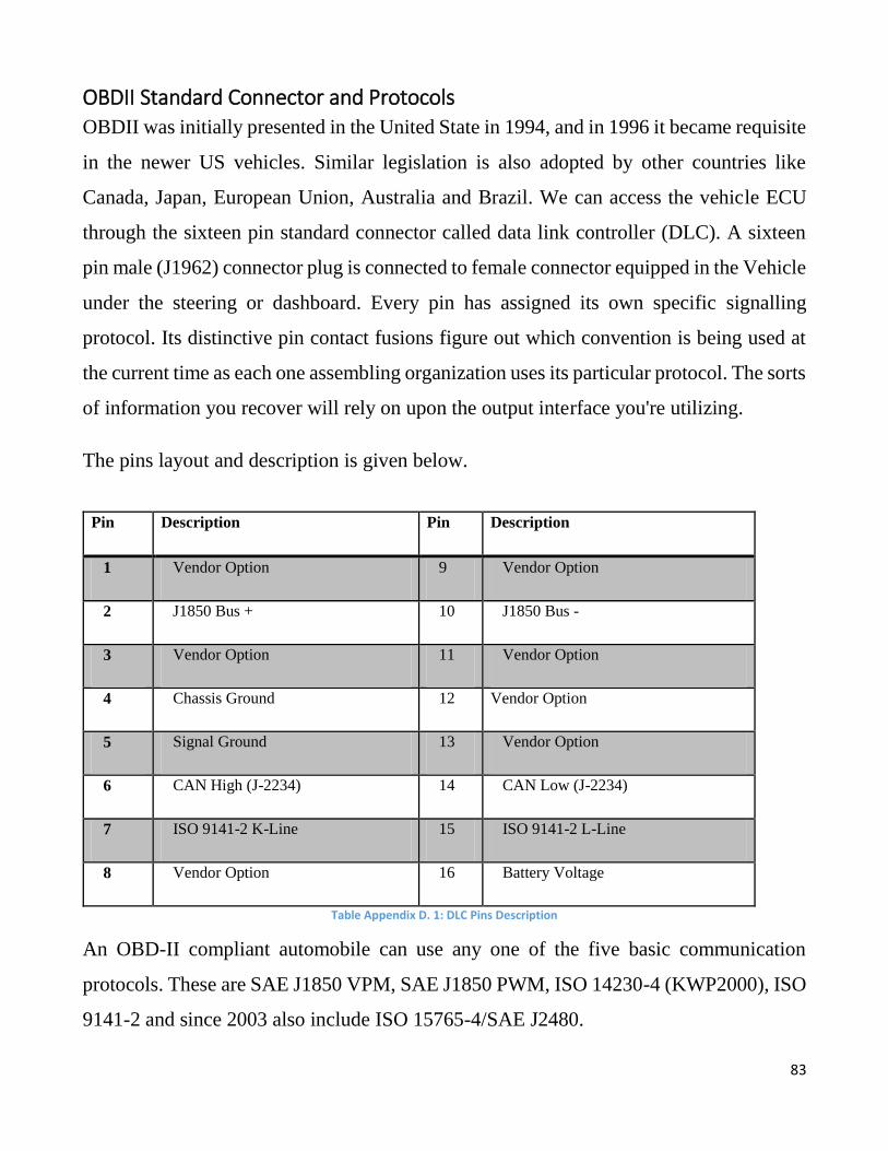
83
OBDII Standard Connector and Protocols OBDII was initially presented in the United State in 1994, and in 1996 it became requisite
in the newer US vehicles. Similar legislation is also adopted by other countries like
Canada, Japan, European Union, Australia and Brazil. We can access the vehicle ECU
through the sixteen pin standard connector called data link controller (DLC). A sixteen
pin male (J1962) connector plug is connected to female connector equipped in the Vehicle
under the steering or dashboard. Every pin has assigned its own specific signalling
protocol. Its distinctive pin contact fusions figure out which convention is being used at
the current time as each one assembling organization uses its particular protocol. The sorts
of information you recover will rely on upon the output interface you're utilizing.
The pins layout and description is given below.
Pin Description Pin Description
1 Vendor Option 9 Vendor Option
2 J1850 Bus + 10 J1850 Bus -
3 Vendor Option 11 Vendor Option
4 Chassis Ground 12 Vendor Option
5 Signal Ground 13 Vendor Option
6 CAN High (J-2234) 14 CAN Low (J-2234)
7 ISO 9141-2 K-Line 15 ISO 9141-2 L-Line
8 Vendor Option 16 Battery Voltage
Table Appendix D. 1: DLC Pins Description
An OBD-II compliant automobile can use any one of the five basic communication
protocols. These are SAE J1850 VPM, SAE J1850 PWM, ISO 14230-4 (KWP2000), ISO
9141-2 and since 2003 also include ISO 15765-4/SAE J2480.

84
DETERMINING PROTOCOL FROM OBD-II PINOUT
When in doubt, we can detect which protocol our vehicle is using by gazing at the pin
layout of the OBDII connector. The following table 4 shows the communicating pins with
respect to specific protocol.
Standard Pin no 2 Pin no 6 Pin no 7 Pin no 10 Pin no
14
Pin no
15
J1850 PWM Must
have
----------- ----------- Must
have
----------- -------------
J1850 VPM Must
have
------------ ----------- ------------ ------------- ------------
ISO9141/14230 ------------- ------------ Must
have
------------ ------------- Optional
ISO15765(CAN) ------------ Must have ---------- ------------ Must have -----------
Table Appendix D. 2: Protocol specification
OBDII Signal Protocol Description
There are five protocols in use with the OBD-II interface, and often it is possible to make
an educated guess about the protocol in use based on which pins are present on the J1962
connector:
a. SAE J1850 PWM (41.6 kbaud, standard of the Ford Motor Company)
(1) pin 2: Bus-
(2) pin 10: Bus+
(3) High voltage is +5V
(4) Message length is restricted to 12 bytes, including CRC
(5) Employs a multi-master arbitration scheme called 'Carrier Sense
Multiple Access with Non-Destructive Arbitration' (CSMA/NDA)
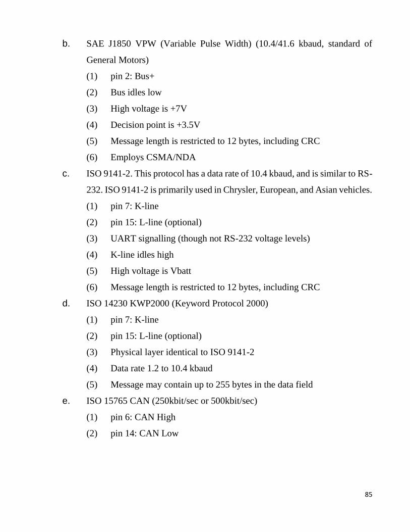
85
b. SAE J1850 VPW (Variable Pulse Width) (10.4/41.6 kbaud, standard of
General Motors)
(1) pin 2: Bus+
(2) Bus idles low
(3) High voltage is +7V
(4) Decision point is +3.5V
(5) Message length is restricted to 12 bytes, including CRC
(6) Employs CSMA/NDA
c. ISO 9141-2. This protocol has a data rate of 10.4 kbaud, and is similar to RS-
232. ISO 9141-2 is primarily used in Chrysler, European, and Asian vehicles.
(1) pin 7: K-line
(2) pin 15: L-line (optional)
(3) UART signalling (though not RS-232 voltage levels)
(4) K-line idles high
(5) High voltage is Vbatt
(6) Message length is restricted to 12 bytes, including CRC
d. ISO 14230 KWP2000 (Keyword Protocol 2000)
(1) pin 7: K-line
(2) pin 15: L-line (optional)
(3) Physical layer identical to ISO 9141-2
(4) Data rate 1.2 to 10.4 kbaud
(5) Message may contain up to 255 bytes in the data field
e. ISO 15765 CAN (250kbit/sec or 500kbit/sec)
(1) pin 6: CAN High
(2) pin 14: CAN Low

86
Note: Pin 5 (Battery ground) and pin 16 (Battery positive) are present in all
configurations. As ISO 9141 and ISO 14230 use the same pin layout, thus we cannot
differentiate between the two by simply examining the DLC connector.
OBDII Diagnostic Data
When there is a troubleshooting problems inside a vehicle, the OBDII retrieve various
data from ECU and provide valuable source of information. The standard SAE J1979
describes a method for requesting numerous diagnostic data and a list of standard
parameter’s that might be available from ECU. The several parameters that are available
are called “parameter identification numbers” OR PIDs. These are explained in J1979.
See appendix A for basic PIDs and their definitions.
The EMC (engine control module), PMC (power control module) constantly monitoring
standard Parameter ID (PID) codes. If the EMC and PMC detect any potential problem
with engine, the warning light call MIL (malfunction indicator light) is lit up to alert the
driver about the problem. After 1996 every vehicle must be capable of sending and
receiving these codes over it OBDII connector.
We need combination of software (Desktop application OR android application) and
hardware (OBDII scan tool) to get these information from ECU. The hardware is acts as
a cable between the diagnostic connector and the device that runs software for reading
codes and data. OBDII provides way for reading codes and all kinds of information. E.g.
live data, test result and ECU information. It record and display any trouble code that the
vehicle is sending. Users can then use the code to see what’s wrong with the vehicle.
What is DTC
Diagnostic trouble codes also known as DTCs are alphanumeric codes that an
automobile's computer yields when it detects a failure. These codes are transferred by a
vehicle's on-board diagnostics (OBD) system and can be read using a diagnostic scanner
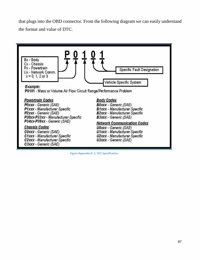
87
that plugs into the OBD connector. From the following diagram we can easily understand
the format and value of DTC.
Figure Appendix D. 1: DTC Specification
88
Bibliography
[1]. Jie, H., Fuwu, Y., Jing, T., Pan, W., & Kai, C. (2010, March). Developing PC-
Based Automobile Diagnostic System Based on OBD System. In Power and
Energy Engineering Conference (APPEEC), 2010 Asia-Pacific (pp. 1-5). IEEE.
[2]. Rosca, G., Daniel-Alexandru, A., Ilina-Elena, I., Cristina, L., Mihai, M., Paval, D.,
& Iftene, A. (2011, June). Remote Equipment Diagnosis using Bluetooth
Communication. In Roedunet International Conference (RoEduNet), 2011 10th (pp.
1-5). IEEE.
[3]. Zaldivar, J., Calafate, C. T., Cano, J. C., & Manzoni, P. (2011, October). Providing
accident detection in vehicular networks through OBD-II devices and Android-
based smartphones. In Local Computer Networks (LCN), 2011 IEEE 36th
Conference on (pp. 813-819). IEEE.
[4]. Tahat, A., Said, A., Jaouni, F., & Qadamani, W. (2012, June). Android-based
universal vehicle diagnostic and tracking system. In Consumer Electronics (ISCE),
2012 IEEE 16th International Symposium on (pp. 137-143). IEEE.
[5]. Siegel, J. E. (2011). Design, development, and validation of a remotely
reconfigurable vehicle telemetry system for consumer and government
applications (Doctoral dissertation, Massachusetts Institute of Technology).
[6]. Bertosa, Thomas, Michael Gessner, and Hamid Namaky. "Diagnostic tool with
advanced diagnostic capabilities." U.S. Patent No. 7,809,482. 5 Oct. 2010.
[7]. Dzhelekarski, P., &Alexiev, D. (2005). Initializing communication to vehicle obdii
system. ELECTRONICS, 5, 21.
[8]. Development of OBD-II driver information system, International Journal of
Engineering and Technology, Vol. 4, No. 2, 2007, pp. 253-259
[9]. M.A.S. Kamal, M. Mukai, J. Murata, T. Kawabe, “On board eco-driving system for
varying road-traffic environments using model predictive control,” 2010 IEEE
International Conference on Control Applications, 2010, pp. 1636-1641.
89
[10]. Noxon, Jeff. “Opendiag OBD-II Schematics & PCB Layout.” Planetfall. N.p., 13
Jan. 2009. Web. 21 Feb. 2011. http://www.planetfall.com/cms/content/ opendiag-
obd-ii-schematics-pcb-layout
[11]. OBD-II Background.” The OBD II Home Page. N.p., 2011. Web. 23 Feb. 2011.
<http://www.obdii.com/background.html>.
[12]. OBD2 Diagnostic Operational Modes.” CanOBD2. Innova, 2011. Web. 18 Feb.
2011.
[13]. OBD FAQ: OBD-II Communication Protocols.” OBD-Codes. N.p., n.d. Web. 21
Mar. 2011. <http://www.obd-codes.com/faq/obd-ii-protocols.php>.
[14]. OBD-II PIDs, http://en.wikipedia.org/wiki/OBD-II_PIDs
[15]. Scantool, http://www.scantool.net/
[16]. Elm Electronics, http://www.elmelectronics.com/
[17]. http://ahdesign.us/blog/stn1170-bluetooth-obdii-adapter/bluetooth-obdii-adapter/
[18]. http://nabiltewolde.blogspot.com/2011/11/bluetooth-obd-ii-adapter.html
[19]. http://nicegear.co.nz/electronics-gear/obdii-uart/
[20]. http://softgyan.com/2009/06/top-5-java-erp-software-11422/
[21]. http://torque-bhp.com/software/torque-android-obd2-adapters/. May 2011
[22]. E.M. Shehab, M.W. Sharp, L. Supramaniam& T.A. Spedding, ‘Enterprise Resource
Planning An Integrative Review’, Business Process Management Journal , Vol. 10,
No. 4, 2004, pp. 359-386
[23]. Magnusson, Monika. "Intentions to Adopt Open Source Software ERP Systems-A
Case Study of Four Swedish Municipalities." In System Sciences (HICSS), 2011
44th Hawaii International Conference on, pp. 1-10. IEEE, 2011.
[24]. http://www.obdsol.com/downloads/stn1110_vs_elm327.pdf


