1
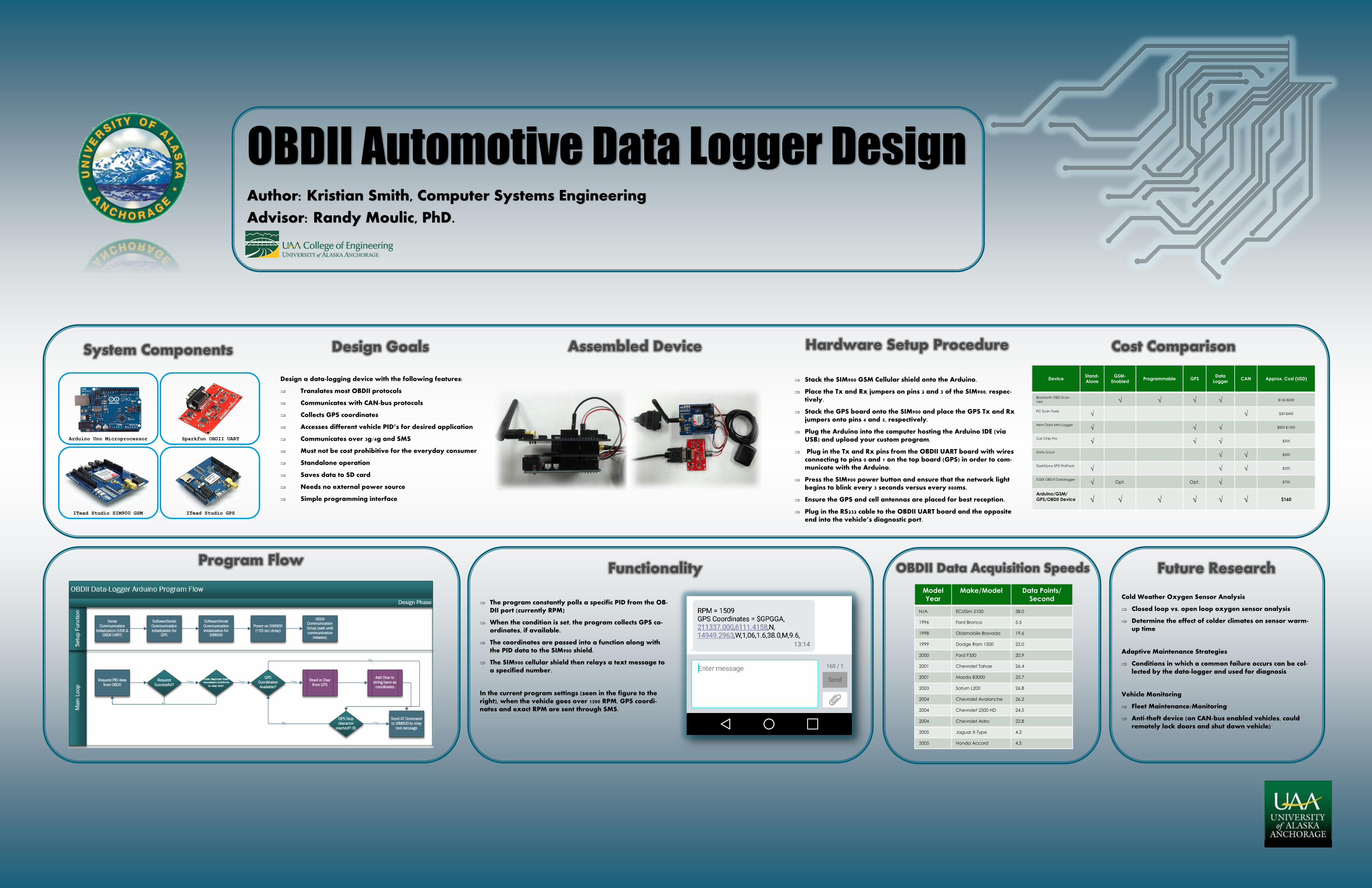
Arduino Uno Microprocessor Sparkfun OBDII UART ITead Studio SIM900 GSM ITead Studio GPS System Components Device Stand- Alone GSM- Enabled Programmable GPS Data Logger CAN Approx. Cost (USD) Bluetooth OBD Scan- ners √ √ √ √ $150-$500 PC Scan Tools √ √ $30-$400 Hem Data Mini Logger √ √ √ $800-$1500 Car Chip Pro √ √ √ $305 Data Scout √ √ $500 DashDyno SPD ProPack √ √ √ $320 IOSiX OBD-II Datalogger √ Opt. Opt. √ $700 Arduino/GSM/ GPS/OBDII Device √ √ √ √ √ √ $160 Cost Comparison Assembled Device OBDII Automotive Data Logger Design Author: Kristian Smith, Computer Systems Engineering Advisor: Randy Moulic, PhD. Design Goals Design a data-logging device with the following features: Translates most OBDII protocols Communicates with CAN-bus protocols Collects GPS coordinates Accesses different vehicle PID’s for desired application Communicates over 3g/4g and SMS Must not be cost prohibitive for the everyday consumer Standalone operation Saves data to SD card Needs no external power source Simple programming interface Hardware Setup Procedure Stack the SIM900 GSM Cellular shield onto the Arduino. Place the Tx and Rx jumpers on pins 2 and 3 of the SIM900, respec- tively. Stack the GPS board onto the SIM900 and place the GPS Tx and Rx jumpers onto pins 4 and 5, respectively. Plug the Arduino into the computer hosting the Arduino IDE (via USB) and upload your custom program. Plug in the Tx and Rx pins from the OBDII UART board with wires connecting to pins 0 and 1 on the top board (GPS) in order to com- municate with the Arduino. Press the SIM900 power button and ensure that the network light begins to blink every 3 seconds versus every 800ms. Ensure the GPS and cell antennas are placed for best reception. Plug in the RS232 cable to the OBDII UART board and the opposite end into the vehicle’s diagnostic port. Functionality The program constantly polls a specific PID from the OB- DII port (currently RPM) When the condition is set, the program collects GPS co- ordinates, if available. The coordinates are passed into a function along with the PID data to the SIM900 shield. The SIM900 cellular shield then relays a text message to a specified number. In the current program settings (seen in the figure to the right), when the vehicle goes over 1500 RPM, GPS coordi- nates and exact RPM are sent through SMS. Future Research Cold Weather Oxygen Sensor Analysis Closed loop vs. open loop oxygen sensor analysis Determine the effect of colder climates on sensor warm- up time Adaptive Maintenance Strategies Conditions in which a common failure occurs can be col- lected by the data-logger and used for diagnosis Vehicle Monitoring Fleet Maintenance/Monitoring Anti-theft device (on CAN-bus enabled vehicles, could remotely lock doors and shut down vehicle) Model Year Make/Model Data Points/ Second N/A ECUSim 5100 38.0 1996 Ford Bronco 5.5 1998 Oldsmobile Bravada 19.6 1999 Dodge Ram 1500 22.0 2000 Ford F350 20.9 2001 Chevrolet Tahoe 26.4 2001 Mazda B3000 25.7 2003 Saturn L200 26.8 2004 Chevrolet Avalanche 26.2 2004 Chevrolet 2500 HD 24.5 2004 Chevrolet Astro 22.8 2005 Jaguar X-Type 4.2 2005 Honda Accord 4.5 OBDII Data Acquisition Speeds Program Flow