8 Object-Handling Tasks Based on Active Tactile and Slippage Sensations Masahiro Ohka 1 , Hanafiah Bin Yussof 2 and Sukarnur Che Abdullah 1,2 1 Nagoya University 2 Universiti Teknologi MARA Japan Malaysia 1. Introduction Many tactile sensors have been developed to enhance robotic manufacturing tasks, such as assembly, disassembly, inspection and materials handling as described in several survey papers (Harmon, 1982; Nicholls & Lee 1989; Ohka, 2009a). In the last decade, progress has been made in tactile sensors by focusing on limited uses. Many examples of practical tactile sensors have gradually appeared. Using a Micro Electro Mechanical System, MEMS-based tactile sensors have been developed to incorporate pressure-sensing elements and piezoelectric ceramic actuators into a silicon tip for detecting not only pressure distribution but also the hardness of a target object (Hasegawa et al., 2004). Using PolyVinylidene DiFluoride, a PVDF film-based tactile sensor has been developed to measure the hardness of tumors based on comparison between the obtained sensor output and the input oscillation (Tanaka et al., 2003). A wireless tactile sensor using two-dimensional signal transmission has been developed to be stretched over a large sensing area (Chigusa et al., 2007). An advanced conductive rubber-type tactile sensor has been developed to be mounted on robotic fingers (Shimojo et al., 2004). Furthermore, image based tactile sensors have been developed using a charge-coupled device (CCD) and complementary metal oxide semiconductor (CMOS) cameras and image data processing, which are mature techniques (Ohka, 1995, 2004, 2005a, 2005b, Kamiyama et al., 2005). In particular, the three-axis tactile sensor that is categorized as an image based tactile sensor has attracted the greatest anticipation for improving manipulation because a robot must detect the distribution not only of normal force but also of slippage force applied to its finger surfaces (Ohka, 1995, 2004, 2005a, 2005b, 2008). In addition to our three-axis tactile sensors, there are several designs of multi-axis force cells based on such physical phenomena as magnetic effects (Hackwood et al., 1986), variations in electrical capacity (Novak, 1989; Hakozaki & Shinoda 2002), PVDF film (Yamada & Cutkosky, 1994), and a photointerrupter (Borovac et al., 1996). Our three-axis tactile sensor is based on the principle of an optical waveguide-type tactile sensor (Mott et al., 1984; Tanie et al., 1986; Nicholls et al., 1990; Kaneko et al., 1992; Maekawa et al., 1992), which is composed of an acrylic hemispherical dome, a light source, an array of rubber sensing elements, and a CCD camera (Ohka, 1995, 2004a, 2005a, 2005b, 2008). The sensing element of the silicone rubber comprises one columnar feeler and eight conical www.intechopen.com
Transcript
8
Object-Handling Tasks Based on Active Tactile and Slippage Sensations
Masahiro Ohka1, Hanafiah Bin Yussof2 and Sukarnur Che Abdullah1,2
1Nagoya University 2Universiti Teknologi MARA
Japan Malaysia
1. Introduction
Many tactile sensors have been developed to enhance robotic manufacturing tasks, such as assembly, disassembly, inspection and materials handling as described in several survey papers (Harmon, 1982; Nicholls & Lee 1989; Ohka, 2009a). In the last decade, progress has been made in tactile sensors by focusing on limited uses. Many examples of practical tactile sensors have gradually appeared. Using a Micro Electro Mechanical System, MEMS-based tactile sensors have been developed to incorporate pressure-sensing elements and piezoelectric ceramic actuators into a silicon tip for detecting not only pressure distribution but also the hardness of a target object (Hasegawa et al., 2004). Using PolyVinylidene DiFluoride, a PVDF film-based tactile sensor has been developed to measure the hardness of tumors based on comparison between the obtained sensor output and the input oscillation (Tanaka et al., 2003). A wireless tactile sensor using two-dimensional signal transmission has been developed to be stretched over a large sensing area (Chigusa et al., 2007). An advanced conductive rubber-type tactile sensor has been developed to be mounted on robotic fingers (Shimojo et al., 2004). Furthermore, image based tactile sensors have been developed using a charge-coupled device (CCD) and complementary metal oxide semiconductor (CMOS) cameras and image data processing, which are mature techniques (Ohka, 1995, 2004, 2005a, 2005b, Kamiyama et al., 2005). In particular, the three-axis tactile sensor that is categorized as an image based tactile sensor has attracted the greatest anticipation for improving manipulation because a robot must detect the distribution not only of normal force but also of slippage force applied to its finger surfaces (Ohka, 1995, 2004, 2005a, 2005b, 2008). In addition to our three-axis tactile sensors, there are several designs of multi-axis force cells based on such physical phenomena as magnetic effects (Hackwood et al., 1986), variations in electrical capacity (Novak, 1989; Hakozaki & Shinoda 2002), PVDF film (Yamada & Cutkosky, 1994), and a photointerrupter (Borovac et al., 1996). Our three-axis tactile sensor is based on the principle of an optical waveguide-type tactile sensor (Mott et al., 1984; Tanie et al., 1986; Nicholls et al., 1990; Kaneko et al., 1992; Maekawa et al., 1992), which is composed of an acrylic hemispherical dome, a light source, an array of rubber sensing elements, and a CCD camera (Ohka, 1995, 2004a, 2005a, 2005b, 2008). The sensing element of the silicone rubber comprises one columnar feeler and eight conical
www.intechopen.com
Robot Arms
138
feelers. The contact areas of the conical feelers, which maintain contact with the acrylic dome, detect the three-axis force applied to the tip of the sensing element. Normal and shearing forces are then calculated from integration and centroid displacement of the grayscale value derived from the conical feeler’s contacts. The tactile sensor is evaluated with a series of experiments using an x-z stage, a rotational stage, and a force gauge. Although we discovered that the relationship between the integrated grayscale value and normal force depends on the sensor’s latitude on the hemispherical surface, it is easy to modify the sensitivity based on the latitude to make the centroid displacement of the grayscale value proportional to the shearing force. To demonstrate the effectiveness of the three-axis tactile sensor, we designed a hand system composed of articulated robotic fingers sensorized with the three-axis tactile sensor (Ohka, 2009b, 2009c). Not only tri-axial force distribution directly obtained from the tactile sensor but also the time derivative of the shearing force distribution are used for the hand control algorithm: the time derivative of tangential force is defined as slippage; if slippage arises, grasping force is enhanced to prevent fatal slippage between the finger and an object. In the verification test, the robotic hand twists on a bottle cap completely. In the following chapters, after the optical three-axis tactile sensor is explained, the robotic hand sensorized with the tactile sensors is described. The above cap-twisting task is discussed to show the effectiveness of tri-axial tactile data for robotic control.
2. Optical three-axis tactile sensor
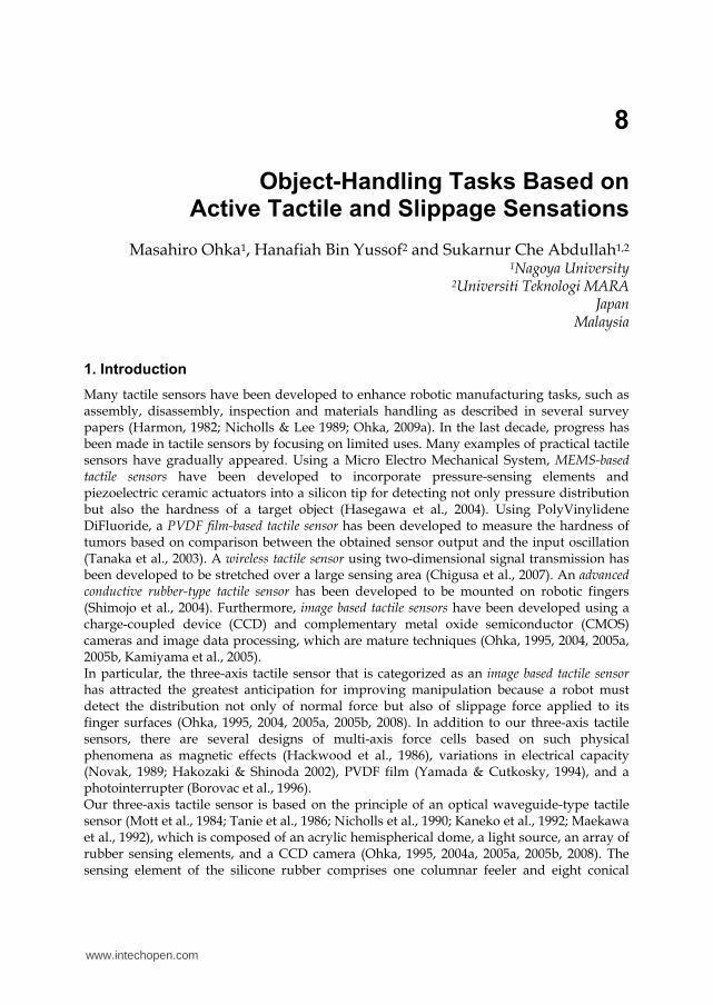
2.1 Sensing principle 2.1.1 Structure of optical tactile sensors Figure 1 shows a schematic view of the present tactile processing system to explain the sensing principle. The present tactile sensor is composed of a CCD camera, an acrylic dome, a light source, and a computer. The light emitted from the light source is directed into the optical waveguide dome. Contact phenomena are observed as image data, acquired by the CCD camera, and transmitted to the computer to calculate the three-axis force distribution.
Fig. 1. Principle of the three-axis tactile sensor system
www.intechopen.com
Object-Handling Tasks Based on Active Tactile and Slippage Sensations
139
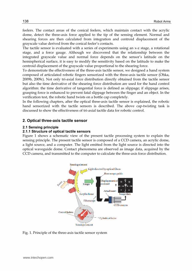
In this chapter, we adopt a sensing element comprised of a columnar feeler and eight conical feelers, as shown in Fig. 2, because the element showed wide measuring range and good linearity in a previous paper (Ohka, 2004b). Since a single sensing element of the present tactile sensor should carry a heavier load compared to a flat-type tactile sensor, the height of the columnar feeler of the flat-type tactile sensor is reduced from 5 to 3 mm. The sensing elements are made of silicone rubber (KE119, Shinetsu) and are designed to maintain contact with the conical feelers and the acrylic board and to make the columnar feelers touch an object. Each columnar feeler features a flange to fit into a counter bore portion in the fixing dome to protect the columnar feeler from horizontal displacement caused by shearing force.
2.1.2 Expressions for sensing element located on vertex Dome brightness is inhomogeneous because the edge of the dome is illuminated and light converges on its parietal region. Since the optical axis coincides with the center line of the vertex, the apparent image of the contact area changes based on the sensing element’s latitude. Although we must consider the above problems to formulate a series of equations for the three components of force, the most basic sensing element located on the vertex will be considered first.
Fig. 2. Sensing element
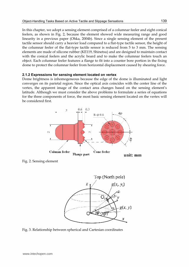
Fig. 3. Relationship between spherical and Cartesian coordinates
www.intechopen.com
Robot Arms
140
Coordinate O-xyz is adopted, as shown in Fig. 3. Based on previous studies (Ohka, 2005),
since grayscale value ,g x y obtained from the image data is proportional to pressure ,p x y caused by contact between the acrylic dome and the conical feeler, normal force is
calculated from integrated grayscale value G . Additionally, shearing force is proportional
to the centroid displacement of the grayscale value. Therefore, the x
F , y
F , and z
F values are
calculated using integrated grayscale value G and the horizontal displacement of the
centroid of grayscale distribution x y
u u u i j as follows:
( )x x x
F f u , (1)
( )y y y
F f u , (2)
( )z
F g G , (3)
where i and j are the orthogonal base vectors of the x- and y-axes of a Cartesian
coordinate, respectively, and ( )x
f x , ( )y
f x , and ( )g x are approximate curves estimated in
calibration experiments.
2.1.3 Expressions for sensing elements other than those located on vertex
For sensing elements other than those located on the vertex, each local coordinate Oi-xiyizi is
attached to the root of the element, where suffix i denotes element number. Each zi-axis is
aligned with the center line of the element and its direction is along the normal direction of
the acrylic dome. The zi-axis in local coordinate Oi-xiyizi is taken along the center line of
sensing element i so that its origin is located on the crossing point of the center line and the
acrylic dome's surface and its direction coincides with the normal direction of the acrylic
dome. If the vertex is likened to the North Pole, the directions of the xi- and yi-axes are north
to south and west to east, respectively. Since the optical axis direction of the CCD camera
coincides with the direction of the z-axis, information of every tactile element is obtained as
an image projected into the O-xy plane. The obtained image data ,g x y should be
transformed into modified image ,i i
g x y , which is assumed to be taken in the negative
direction of the zi-axis attached to each sensing element. The transform expression is derived
from the coordinate transformation of the spherical coordinate to the Cartesian coordinate
as follows:
( , ) ( , ) /sini i i
g x y g x y (4)
Centroid displacements included in Eqs. (1) and (2), and ,x
u x y and ,y
u x y should be
transformed into ,x i i
u x y and ,y i i
u x y as well. In the same way as Eq. (4), the transform
expression is derived from the coordinate transformation of the spherical coordinate to the
Cartesian coordinate as follows:
( , )cos ( , )sin
( , )sin
x i y i
x i i
i
u x y u x yu x y
, (5)
( , ) ( , )sin ( , )cosy i i x i y i
u x y u x y u x y . (6)
www.intechopen.com
Object-Handling Tasks Based on Active Tactile and Slippage Sensations
141
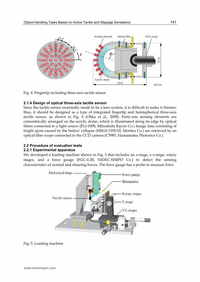
Fig. 4. Fingertip including three-axis tactile sensor
2.1.4 Design of optical three-axis tactile sensor
Since the tactile sensor essentially needs to be a lens system, it is difficult to make it thinner; thus, it should be designed as a type of integrated fingertip and hemispherical three-axis tactile sensor, as shown in Fig. 4 (Ohka et al., 2008). Forty-one sensing elements are concentrically arranged on the acrylic dome, which is illuminated along its edge by optical fibers connected to a light source (ELI-100S, Mitsubishi Rayon Co.) Image data consisting of bright spots caused by the feelers’ collapse (MSGS-1350-III, Moritex Co.) are retrieved by an optical fiber scope connected to the CCD camera (C5985, Hamamatsu Photonics Co.)
2.2 Procedure of evaluation tests 2.2.1 Experimental apparatus
We developed a loading machine shown in Fig. 5 that includes an x-stage, a z-stage, rotary
stages, and a force gauge (FGC-0.2B, NIDEC-SIMPO Co.) to detect the sensing
characteristics of normal and shearing forces. The force gauge has a probe to measure force
Fig. 5. Loading machine
www.intechopen.com
Robot Arms
142
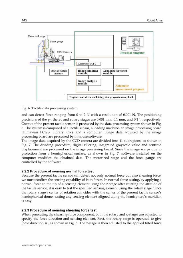
Fig. 6. Tactile data processing system
and can detect force ranging from 0 to 2 N with a resolution of 0.001 N. The positioning
precisions of the y-, the z-, and rotary stages are 0.001 mm, 0.1 mm, and 0.1 , respectively. Output of the present tactile sensor is processed by the data processing system shown in Fig. 6. The system is composed of a tactile sensor, a loading machine, an image processing board (Himawari PCI/S, Library, Co.), and a computer. Image data acquired by the image processing board are processed by in-house software. The image data acquired by the CCD camera are divided into 41 subregions, as shown in Fig. 7. The dividing procedure, digital filtering, integrated grayscale value and centroid displacement are processed on the image processing board. Since the image warps due to projection from a hemispherical surface, as shown in Fig. 7, software installed on the computer modifies the obtained data. The motorized stage and the force gauge are controlled by the software.
2.2.2 Procedure of sensing normal force test
Because the present tactile sensor can detect not only normal force but also shearing force, we must confirm the sensing capability of both forces. In normal-force testing, by applying a normal force to the tip of a sensing element using the z-stage after rotating the attitude of the tactile sensor, it is easy to test the specified sensing element using the rotary stage. Since the rotary stage’s center of rotation coincides with the center of the present tactile sensor’s hemispherical dome, testing any sensing element aligned along the hemisphere’s meridian is easy.
2.2.3 Procedure of sensing shearing force test
When generating the shearing-force component, both the rotary and x-stages are adjusted to specify the force direction and sensing element. First, the rotary stage is operated to give
force direction , as shown in Fig. 8. The x-stage is then adjusted to the applied tilted force
www.intechopen.com
Object-Handling Tasks Based on Active Tactile and Slippage Sensations
143
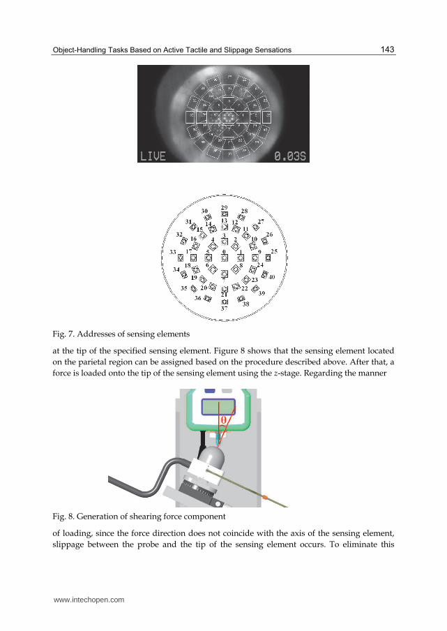
Fig. 7. Addresses of sensing elements
at the tip of the specified sensing element. Figure 8 shows that the sensing element located
on the parietal region can be assigned based on the procedure described above. After that, a
force is loaded onto the tip of the sensing element using the z-stage. Regarding the manner
Fig. 8. Generation of shearing force component
of loading, since the force direction does not coincide with the axis of the sensing element,
slippage between the probe and the tip of the sensing element occurs. To eliminate this
www.intechopen.com
Robot Arms
144
problem, a spherical concave portion is formed on the probe surface to mate the concave
portion with the hemispherical tip of the tactile element. Normal force N
F and shearing
force S
F applied to the sensing elements are calculated using the following formulas, when
force F is applied to the tip of the tactile element:
cosN
F F (7)
sinS
F F (8)
2.3 Sensing ability of optical three-axis tactile sensor 2.3.1 Sensing ability of normal force
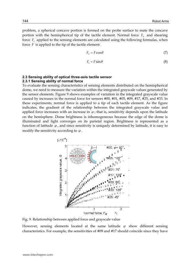
To evaluate the sensing characteristics of sensing elements distributed on the hemispherical dome, we need to measure the variation within the integrated grayscale values generated by the sensor elements. Figure 9 shows examples of variation in the integrated grayscale value caused by increases in the normal force for sensors #00, #01, #05, #09, #17, #25, and #33. In these experiments, normal force is applied to a tip of each tactile element. As the figure indicates, the gradient of the relationship between the integrated grayscale value and applied force increases with an increase in ; that is, sensitivity depends upon the latitude
on the hemisphere. Dome brightness is inhomogeneous because the edge of the dome is illuminated and light converges on its parietal region. Brightness is represented as a function of latitude , and since sensitivity is uniquely determined by latitude, it is easy to
modify the sensitivity according to .
Fig. 9. Relationship between applied force and grayscale value
However, sensing elements located at the same latitude show different sensing
characteristics. For example, the sensitivities of #09 and #17 should coincide since they have
www.intechopen.com
Object-Handling Tasks Based on Active Tactile and Slippage Sensations
145
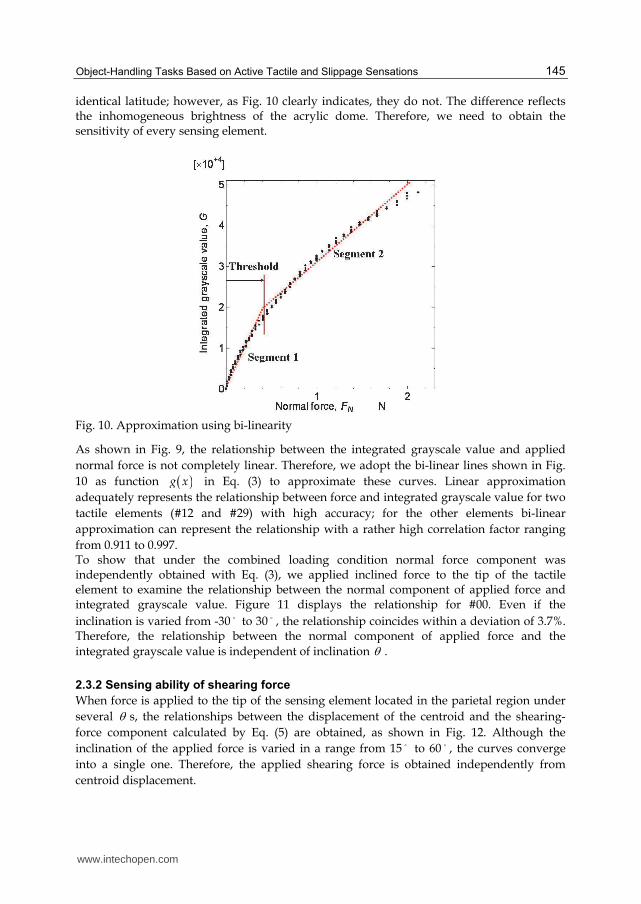
identical latitude; however, as Fig. 10 clearly indicates, they do not. The difference reflects the inhomogeneous brightness of the acrylic dome. Therefore, we need to obtain the sensitivity of every sensing element.
Fig. 10. Approximation using bi-linearity
As shown in Fig. 9, the relationship between the integrated grayscale value and applied
normal force is not completely linear. Therefore, we adopt the bi-linear lines shown in Fig.
10 as function g x in Eq. (3) to approximate these curves. Linear approximation
adequately represents the relationship between force and integrated grayscale value for two
tactile elements (#12 and #29) with high accuracy; for the other elements bi-linear
approximation can represent the relationship with a rather high correlation factor ranging
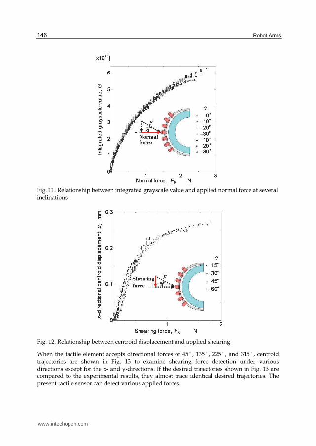
from 0.911 to 0.997. To show that under the combined loading condition normal force component was independently obtained with Eq. (3), we applied inclined force to the tip of the tactile element to examine the relationship between the normal component of applied force and integrated grayscale value. Figure 11 displays the relationship for #00. Even if the
inclination is varied from -30 to 30 , the relationship coincides within a deviation of 3.7%. Therefore, the relationship between the normal component of applied force and the
integrated grayscale value is independent of inclination .
2.3.2 Sensing ability of shearing force
When force is applied to the tip of the sensing element located in the parietal region under
several s, the relationships between the displacement of the centroid and the shearing-
force component calculated by Eq. (5) are obtained, as shown in Fig. 12. Although the
inclination of the applied force is varied in a range from 15 to 60 , the curves converge
into a single one. Therefore, the applied shearing force is obtained independently from
centroid displacement.
www.intechopen.com
Robot Arms
146
Fig. 11. Relationship between integrated grayscale value and applied normal force at several inclinations
Fig. 12. Relationship between centroid displacement and applied shearing
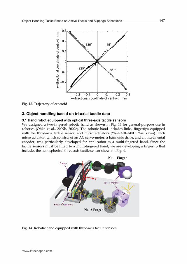
When the tactile element accepts directional forces of 45 , 135 , 225 , and 315 , centroid trajectories are shown in Fig. 13 to examine shearing force detection under various directions except for the x- and y-directions. If the desired trajectories shown in Fig. 13 are compared to the experimental results, they almost trace identical desired trajectories. The present tactile sensor can detect various applied forces.
www.intechopen.com
Object-Handling Tasks Based on Active Tactile and Slippage Sensations
147
–0.2 –0.1 0 0.1 0.2 0.3
–0.2
–0.1
0
0.1
0.2
0.3
x–directional coordinate of centroid mm
y–
dir
ectio
na
l co
ord
ina
te o
f ce
ntr
oid
m
m
45°135°
225°315°
O
Fig. 13. Trajectory of centroid
3. Object handling based on tri-axial tactile data
3.1 Hand robot equipped with optical three-axis tactile sensors
We designed a two-fingered robotic hand as shown in Fig. 14 for general-purpose use in robotics (Ohka et al., 2009b, 2009c). The robotic hand includes links, fingertips equipped with the three-axis tactile sensor, and micro actuators (YR-KA01-A000, Yasukawa). Each micro actuator, which consists of an AC servo-motor, a harmonic drive, and an incremental encoder, was particularly developed for application to a multi-fingered hand. Since the tactile sensors must be fitted to a multi-fingered hand, we are developing a fingertip that includes the hemispherical three-axis tactile sensor shown in Fig. 4.
Fig. 14. Robotic hand equipped with three-axis tactile sensors
www.intechopen.com
Robot Arms
148
3.2 Kinematics of hand robot
As shown in Fig. 14, each robotic finger has three movable joints. The frame of the
workspace is set on the bottom of the z-stage. The kinematics of the present hand is derived
according to Denavit-Hartenberg notation shown in Fig. 14. The frame of the workspace is
defined as O-xyz. The frames of Oi- ( i i ix y z ) (in the following, O-xyz is used instead of O0-
0 0 0x y z ) are attached on each joint, the basement of the z-stage, or the fingertip, as shown in
Fig. 14. The velocities of the micro actuators ( 1 2 3 θ ) are calculated with
1θ J θ r (9)
to satisfy specified velocity vector r ( x y z ), which is calculated from the planed
trajectory. Jacobian J θ is obtained by the kinematics of the robotic hand as follows:
13 2 3 2 4 23 3 11 3 12 3 4 12 12 4
23 2 3 2 4 23 3 21 3 22 3 4 22 22 4
33 2 3 2 4 23 3 31 3 32 3 4 32 32 4
,
R l l c l c l R s R c l R R l
R l l c l c l R s R c l R R l
R l l c l c l R s R c l R R l
J θ (10)
where
11 12 13 11 23 13 23 11 23 13 23 12
21 22 23 21 23 23 23 21 23 23 23 22
31 32 33 31 23 33 23 31 23 33 33 32
,
R R R a c a s a s a c a
R R R a c a s a s a c a
R R R a c a s a s a c a
11 12 13 1 1 1 2 1 1 1 1 2 1 1 2
21 22 23 2 1 2 1 2
31 32 33 1 1 1 2 1 1 1 1 2 1 1 2
a a a c c s s s c s s s s s c
a a a c s c s s
a a a s c s s s s s c s c c c
(11)
cosi i
c , sini i
s , cosi i
c , sini i
s ,
cosij i j
c , sinij i j
s , ( i ; 1, 2, 3j ).
In the above equations, the rotations of the first frame around the 0
x - and 0
y -axes are
denoted as 1
and 2
, respectively. The distance between the origins of the m-th and m+1-
th frames is denoted as m
l . The joint angles of the micro actuators on O2- 2 2 2x y z , O3- 3 3 3
x y z
and O4- 4 4 4x y z are
1 ,
2 , and
3 , respectively.
Position control of the fingertip is performed based on resolved motion rate control. In this
control method, joint angles are assumed at the first step, and displacement vector 0
r is
calculated with kinematics. Adjustment of joint angles is obtained by Eq. (9) and the
difference between 0
r and objective vector d
r to modify joint angle 1tθ at the next step.
The modified joint angle is designated as the current angle in the next step, and the above
procedure is repeated until the displacement vector at k-th step k
r coincides with objective
vector d
r within a specified error. That is, the following Eqs. (12) and (13) are calculated
until d kr r becomes small enough:
k kr Jθ (12)
www.intechopen.com
Object-Handling Tasks Based on Active Tactile and Slippage Sensations
149
1
1k k d k
θ θ J r r (13)
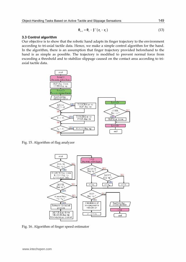
3.3 Control algorithm
Our objective is to show that the robotic hand adapts its finger trajectory to the environment according to tri-axial tactile data. Hence, we make a simple control algorithm for the hand. In the algorithm, there is an assumption that finger trajectory provided beforehand to the hand is as simple as possible. The trajectory is modified to prevent normal force from exceeding a threshold and to stabilize slippage caused on the contact area according to tri-axial tactile data.
Fig. 15. Algorithm of flag analyzer
Fig. 16. Algorithm of finger speed estimator
www.intechopen.com
Robot Arms
150
The hand is controlled according to velocity control. First, hand status becomes “search
mode” to make fingers approach an object with finger speed 0
v v . After the fingers touch
the object, the hand status becomes “move mode” to manipulate the object with finger speed
mv v . During both search and move modes, when the absolute time derivative of the
shearing force of a sensing element exceeds a threshold dr , this system regards the sensing
element as slippage. To prevent the hand from dropping the object, re-compressive velocity
is defined as moving the fingertip along the counter direction of applied force.
However, if normal force of a sensing element exceeds a threshold 2
F , the re-compressive
velocity is cancelled to prevent the sensing element from breaking. The hand is controlled
by a control module with applying total velocity obtained by adding the re-compressive
velocity to current velocity.
In our system, the sensor control program and hand control program are executed in
different computers because CPU time is efficiently consumed using a multi-task program
method. These programs are synchronized with the following five flags.
SEARCH: Fingers search for an object with initial finger velocity 0
v until normal force of a
sensing element exceeds a threshold 1
F or Slip flag is raised. MOVE: This flag is raised whenever the robotic hand manipulates an object. TOUCH: This flag is raised whenever one of the fingers touches an object. SLIP: This flag is raised whenever the time derivative of shearing force exceeds a threshold
dr .
OVER: This flag is raised when normal force of a sensing element exceeds a threshold 2
F . These flags are decided according to tri-axial tactile data and finger motions. Since two modules, the flag analyzer and finger speed estimator, mainly play the role of object handling, these modules are shown in Figs. 15 and 16, respectively.
In the flag analyzer, TOUCH flag, SLIP flag and OVER flag are decided. The flag analyzer
regards finger status as touching an object when normal force of a sensing element is
exceeded or the absolute time derivative of the shearing force is exceeded (SLIP flag is
raised). Whenever it regards finger status as touching an object, the TOUCH flag is raised.
The OVER flag is raised when normal force of a sensing element exceeds 1
F to prohibit re-
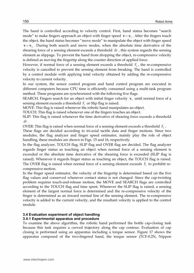
compressive motion. In the finger speed estimator, the velocity of the fingertip is determined based on the five flag values and conserved whenever contact status is not changed. Since the cap-twisting problem requires touch-and-release motion, the MOVE and SEARCH flags are controlled according to the TOUCH flag and time spent. Whenever the SLIP flag is raised, a sensing element of the largest normal force is determined and the re-compressive velocity of the finger is determined as an inward normal line of the sensing element. The re-compressive velocity is added to the current velocity, and the resultant velocity is applied to the control module.
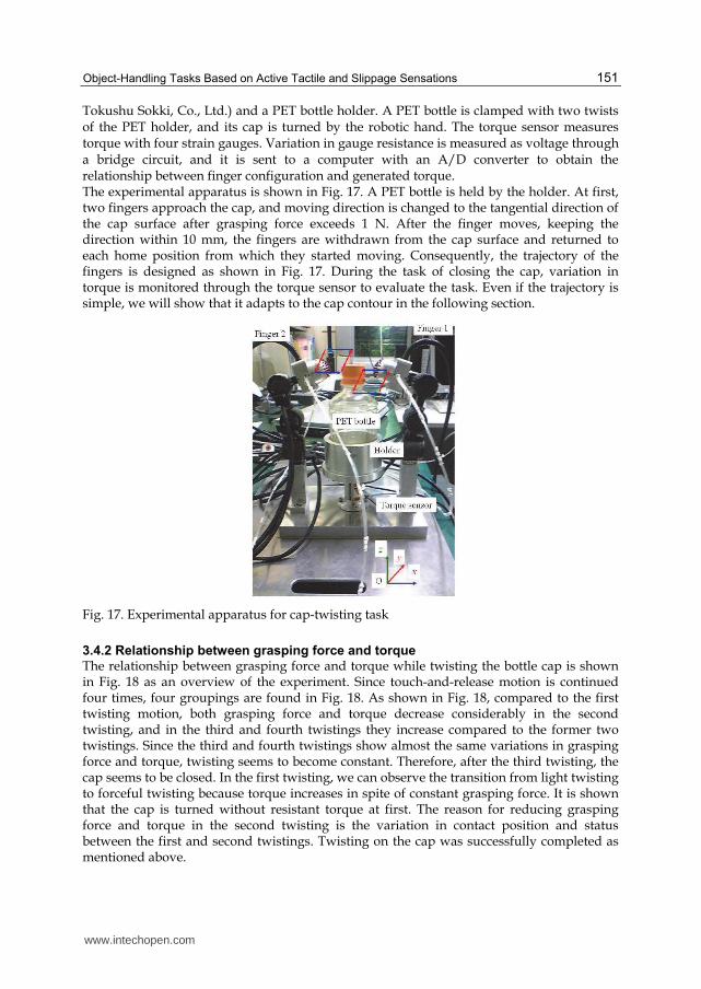
3.4 Evaluation experiment of object handling 3.4.1 Experimental apparatus and procedure
To examine the above algorithm, the robotic hand performed the bottle cap-closing task because this task requires a curved trajectory along the cap contour. Evaluation of cap closing is performed using an apparatus including a torque sensor. Figure 17 shows the apparatus composed of the two-fingered hand, the torque sensor (TCF-0.2N, Nippon
www.intechopen.com
Object-Handling Tasks Based on Active Tactile and Slippage Sensations
151
Tokushu Sokki, Co., Ltd.) and a PET bottle holder. A PET bottle is clamped with two twists of the PET holder, and its cap is turned by the robotic hand. The torque sensor measures torque with four strain gauges. Variation in gauge resistance is measured as voltage through a bridge circuit, and it is sent to a computer with an A/D converter to obtain the relationship between finger configuration and generated torque. The experimental apparatus is shown in Fig. 17. A PET bottle is held by the holder. At first, two fingers approach the cap, and moving direction is changed to the tangential direction of the cap surface after grasping force exceeds 1 N. After the finger moves, keeping the direction within 10 mm, the fingers are withdrawn from the cap surface and returned to each home position from which they started moving. Consequently, the trajectory of the fingers is designed as shown in Fig. 17. During the task of closing the cap, variation in torque is monitored through the torque sensor to evaluate the task. Even if the trajectory is simple, we will show that it adapts to the cap contour in the following section.
Fig. 17. Experimental apparatus for cap-twisting task
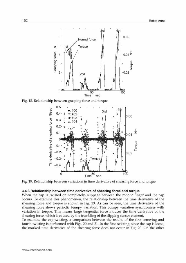
3.4.2 Relationship between grasping force and torque
The relationship between grasping force and torque while twisting the bottle cap is shown in Fig. 18 as an overview of the experiment. Since touch-and-release motion is continued four times, four groupings are found in Fig. 18. As shown in Fig. 18, compared to the first twisting motion, both grasping force and torque decrease considerably in the second twisting, and in the third and fourth twistings they increase compared to the former two twistings. Since the third and fourth twistings show almost the same variations in grasping force and torque, twisting seems to become constant. Therefore, after the third twisting, the cap seems to be closed. In the first twisting, we can observe the transition from light twisting to forceful twisting because torque increases in spite of constant grasping force. It is shown that the cap is turned without resistant torque at first. The reason for reducing grasping force and torque in the second twisting is the variation in contact position and status between the first and second twistings. Twisting on the cap was successfully completed as mentioned above.
www.intechopen.com
Robot Arms
152
50 1000
2
4
6
0
0.02
0.04
0.06
Time sec
Gra
sp
ing
fo
rce
N
To
rqu
e N
m
Normal force
Torque1st
2nd
3rd 4th
Fig. 18. Relationship between grasping force and torque
0 50 100
–0.4
–0.3
–0.2
–0.1
0
0.1
0.2
0.3
0.4
0.5
0
0.02
0.04
0.06
Time sec
Tim
e d
eri
va
tive
of sh
ea
rin
g fo
rce
N
/se
c
To
rqu
e N
m
Torque
: #00: #02: #03: #04
1st
2nd
3rd4th
Fig. 19. Relationship between variations in time derivative of shearing force and torque
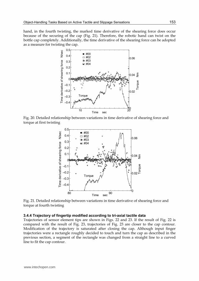
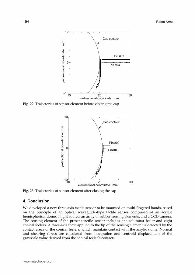
3.4.3 Relationship between time derivative of shearing force and torque When the cap is twisted on completely, slippage between the robotic finger and the cap occurs. To examine this phenomenon, the relationship between the time derivative of the shearing force and torque is shown in Fig. 19. As can be seen, the time derivative of the shearing force shows periodic bumpy variation. This bumpy variation synchronizes with variation in torque. This means large tangential force induces the time derivative of the shearing force, which is caused by the trembling of the slipping sensor element. To examine the cap-twisting, a comparison between the results of the first screwing and fourth twisting is performed with Figs. 20 and 21. In the first twisting, since the cap is loose, the marked time derivative of the shearing force does not occur in Fig. 20. On the other
www.intechopen.com
Object-Handling Tasks Based on Active Tactile and Slippage Sensations
153
hand, in the fourth twisting, the marked time derivative of the shearing force does occur because of the securing of the cap (Fig. 21). Therefore, the robotic hand can twist on the bottle cap completely. Additionally, the time derivative of the shearing force can be adopted as a measure for twisting the cap.
10 20
–0.4
–0.3
–0.2
–0.1
0
0.1
0.2
0.3
0.4
0.5
0
0.02
0.04
0.06
Time sec
Tim
e d
eri
va
tive
of sh
ea
rin
g fo
rce
N
/se
c
To
rqu
e N
m
Torque
: #00: #02: #03: #04
Fig. 20. Detailed relationship between variations in time derivative of shearing force and torque at first twisting
80 90
–0.4
–0.3
–0.2
–0.1
0
0.1
0.2
0.3
0.4
0.5
0
0.02
0.04
0.06
Time sec
Tim
e d
eri
va
tive
of sh
ea
rin
g fo
rce
N
/se
c
To
rqu
e N
m
Torque
: #00: #02: #03: #04
Fig. 21. Detailed relationship between variations in time derivative of shearing force and torque at fourth twisting
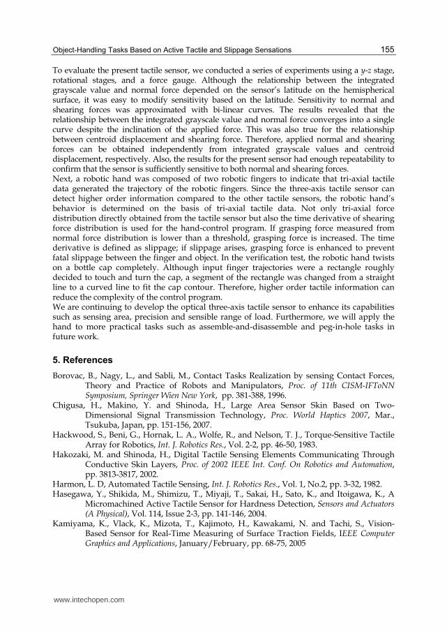
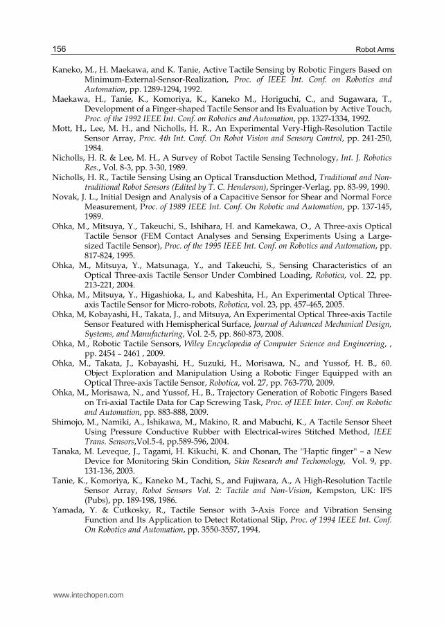
3.4.4 Trajectory of fingertip modified according to tri-axial tactile data Trajectories of sensor element tips are shown in Figs. 22 and 23. If the result of Fig. 22 is compared with the result of Fig. 23, trajectories of Fig. 23 are closer to the cap contour. Modification of the trajectory is saturated after closing the cap. Although input finger trajectories were a rectangle roughly decided to touch and turn the cap as described in the previous section, a segment of the rectangle was changed from a straight line to a curved line to fit the cap contour.
www.intechopen.com
Robot Arms
154
10 20 30–10
0
10
x–directional coordinate mm
y–
dir
ectio
na
l co
ord
ina
te m
m
Pin #02
Pin #03
Cap contour
Fig. 22. Trajectories of sensor element before closing the cap
10 20 30–10
0
10
x–directional coordinate mm
y–
dir
ectio
na
l co
ord
ina
te m
m
Pin #02
Pin #03
Cap contour
Fig. 23. Trajectories of sensor element after closing the cap
4. Conclusion
We developed a new three-axis tactile sensor to be mounted on multi-fingered hands, based on the principle of an optical waveguide-type tactile sensor comprised of an acrylic hemispherical dome, a light source, an array of rubber sensing elements, and a CCD camera. The sensing element of the present tactile sensor includes one columnar feeler and eight conical feelers. A three-axis force applied to the tip of the sensing element is detected by the contact areas of the conical feelers, which maintain contact with the acrylic dome. Normal and shearing forces are calculated from integration and centroid displacement of the grayscale value derived from the conical feeler’s contacts.
www.intechopen.com
Object-Handling Tasks Based on Active Tactile and Slippage Sensations
155
To evaluate the present tactile sensor, we conducted a series of experiments using a y-z stage, rotational stages, and a force gauge. Although the relationship between the integrated grayscale value and normal force depended on the sensor’s latitude on the hemispherical surface, it was easy to modify sensitivity based on the latitude. Sensitivity to normal and shearing forces was approximated with bi-linear curves. The results revealed that the relationship between the integrated grayscale value and normal force converges into a single curve despite the inclination of the applied force. This was also true for the relationship between centroid displacement and shearing force. Therefore, applied normal and shearing forces can be obtained independently from integrated grayscale values and centroid displacement, respectively. Also, the results for the present sensor had enough repeatability to confirm that the sensor is sufficiently sensitive to both normal and shearing forces. Next, a robotic hand was composed of two robotic fingers to indicate that tri-axial tactile data generated the trajectory of the robotic fingers. Since the three-axis tactile sensor can detect higher order information compared to the other tactile sensors, the robotic hand’s behavior is determined on the basis of tri-axial tactile data. Not only tri-axial force distribution directly obtained from the tactile sensor but also the time derivative of shearing force distribution is used for the hand-control program. If grasping force measured from normal force distribution is lower than a threshold, grasping force is increased. The time derivative is defined as slippage; if slippage arises, grasping force is enhanced to prevent fatal slippage between the finger and object. In the verification test, the robotic hand twists on a bottle cap completely. Although input finger trajectories were a rectangle roughly decided to touch and turn the cap, a segment of the rectangle was changed from a straight line to a curved line to fit the cap contour. Therefore, higher order tactile information can reduce the complexity of the control program. We are continuing to develop the optical three-axis tactile sensor to enhance its capabilities such as sensing area, precision and sensible range of load. Furthermore, we will apply the hand to more practical tasks such as assemble-and-disassemble and peg-in-hole tasks in future work.
5. References
Borovac, B., Nagy, L., and Sabli, M., Contact Tasks Realization by sensing Contact Forces, Theory and Practice of Robots and Manipulators, Proc. of 11th CISM-IFToNN Symposium, Springer Wien New York, pp. 381-388, 1996.
Chigusa, H., Makino, Y. and Shinoda, H., Large Area Sensor Skin Based on Two-Dimensional Signal Transmission Technology, Proc. World Haptics 2007, Mar., Tsukuba, Japan, pp. 151-156, 2007.
Hackwood, S., Beni, G., Hornak, L. A., Wolfe, R., and Nelson, T. J., Torque-Sensitive Tactile Array for Robotics, Int. J. Robotics Res., Vol. 2-2, pp. 46-50, 1983.
Hakozaki, M. and Shinoda, H., Digital Tactile Sensing Elements Communicating Through Conductive Skin Layers, Proc. of 2002 IEEE Int. Conf. On Robotics and Automation, pp. 3813-3817, 2002.
Harmon, L. D, Automated Tactile Sensing, Int. J. Robotics Res., Vol. 1, No.2, pp. 3-32, 1982. Hasegawa, Y., Shikida, M., Shimizu, T., Miyaji, T., Sakai, H., Sato, K., and Itoigawa, K., A
Micromachined Active Tactile Sensor for Hardness Detection, Sensors and Actuators (A Physical), Vol. 114, Issue 2-3, pp. 141-146, 2004.
Kamiyama, K., Vlack, K., Mizota, T., Kajimoto, H., Kawakami, N. and Tachi, S., Vision-Based Sensor for Real-Time Measuring of Surface Traction Fields, IEEE Computer Graphics and Applications, January/February, pp. 68-75, 2005
www.intechopen.com
Robot Arms
156
Kaneko, M., H. Maekawa, and K. Tanie, Active Tactile Sensing by Robotic Fingers Based on Minimum-External-Sensor-Realization, Proc. of IEEE Int. Conf. on Robotics and Automation, pp. 1289-1294, 1992.
Maekawa, H., Tanie, K., Komoriya, K., Kaneko M., Horiguchi, C., and Sugawara, T., Development of a Finger-shaped Tactile Sensor and Its Evaluation by Active Touch, Proc. of the 1992 IEEE Int. Conf. on Robotics and Automation, pp. 1327-1334, 1992.
Mott, H., Lee, M. H., and Nicholls, H. R., An Experimental Very-High-Resolution Tactile Sensor Array, Proc. 4th Int. Conf. On Robot Vision and Sensory Control, pp. 241-250, 1984.
Nicholls, H. R. & Lee, M. H., A Survey of Robot Tactile Sensing Technology, Int. J. Robotics Res., Vol. 8-3, pp. 3-30, 1989.
Nicholls, H. R., Tactile Sensing Using an Optical Transduction Method, Traditional and Non-traditional Robot Sensors (Edited by T. C. Henderson), Springer-Verlag, pp. 83-99, 1990.
Novak, J. L., Initial Design and Analysis of a Capacitive Sensor for Shear and Normal Force Measurement, Proc. of 1989 IEEE Int. Conf. On Robotic and Automation, pp. 137-145, 1989.
Ohka, M., Mitsuya, Y., Takeuchi, S., Ishihara, H. and Kamekawa, O., A Three-axis Optical Tactile Sensor (FEM Contact Analyses and Sensing Experiments Using a Large-sized Tactile Sensor), Proc. of the 1995 IEEE Int. Conf. on Robotics and Automation, pp. 817-824, 1995.
Ohka, M., Mitsuya, Y., Matsunaga, Y., and Takeuchi, S., Sensing Characteristics of an Optical Three-axis Tactile Sensor Under Combined Loading, Robotica, vol. 22, pp. 213-221, 2004.
Ohka, M., Mitsuya, Y., Higashioka, I., and Kabeshita, H., An Experimental Optical Three-axis Tactile Sensor for Micro-robots, Robotica, vol. 23, pp. 457-465, 2005.
Ohka, M, Kobayashi, H., Takata, J., and Mitsuya, An Experimental Optical Three-axis Tactile Sensor Featured with Hemispherical Surface, Journal of Advanced Mechanical Design, Systems, and Manufacturing, Vol. 2-5, pp. 860-873, 2008.
Ohka, M., Robotic Tactile Sensors, Wiley Encyclopedia of Computer Science and Engineering, , pp. 2454 – 2461 , 2009.
Ohka, M., Takata, J., Kobayashi, H., Suzuki, H., Morisawa, N., and Yussof, H. B., 60. Object Exploration and Manipulation Using a Robotic Finger Equipped with an Optical Three-axis Tactile Sensor, Robotica, vol. 27, pp. 763-770, 2009.
Ohka, M., Morisawa, N., and Yussof, H., B., Trajectory Generation of Robotic Fingers Based on Tri-axial Tactile Data for Cap Screwing Task, Proc. of IEEE Inter. Conf. on Robotic and Automation, pp. 883-888, 2009.
Shimojo, M., Namiki, A., Ishikawa, M., Makino, R. and Mabuchi, K., A Tactile Sensor Sheet Using Pressure Conductive Rubber with Electrical-wires Stitched Method, IEEE Trans. Sensors,Vol.5-4, pp.589-596, 2004.
Tanaka, M. Leveque, J., Tagami, H. Kikuchi, K. and Chonan, The ''Haptic finger'' – a New Device for Monitoring Skin Condition, Skin Research and Techonology, Vol. 9, pp. 131-136, 2003.
Tanie, K., Komoriya, K., Kaneko M., Tachi, S., and Fujiwara, A., A High-Resolution Tactile Sensor Array, Robot Sensors Vol. 2: Tactile and Non-Vision, Kempston, UK: IFS (Pubs), pp. 189-198, 1986.
Yamada, Y. & Cutkosky, R., Tactile Sensor with 3-Axis Force and Vibration Sensing Function and Its Application to Detect Rotational Slip, Proc. of 1994 IEEE Int. Conf. On Robotics and Automation, pp. 3550-3557, 1994.
www.intechopen.com
Robot ArmsEdited by Prof. Satoru Goto
ISBN 978-953-307-160-2Hard cover, 262 pagesPublisher InTechPublished online 09, June, 2011Published in print edition June, 2011
InTech ChinaUnit 405, Office Block, Hotel Equatorial Shanghai No.65, Yan An Road (West), Shanghai, 200040, China
Phone: +86-21-62489820 Fax: +86-21-62489821
Robot arms have been developing since 1960's, and those are widely used in industrial factories such aswelding, painting, assembly, transportation, etc. Nowadays, the robot arms are indispensable for automation offactories. Moreover, applications of the robot arms are not limited to the industrial factory but expanded toliving space or outer space. The robot arm is an integrated technology, and its technological elements areactuators, sensors, mechanism, control and system, etc.
How to referenceIn order to correctly reference this scholarly work, feel free to copy and paste the following:
Masahiro Ohka, Hanafiah Bin Yussof and Sukarnur Che Abdullah (2011). Object-Handling Tasks Based onActive Tactile and Slippage Sensations, Robot Arms, Prof. Satoru Goto (Ed.), ISBN: 978-953-307-160-2,InTech, Available from: http://www.intechopen.com/books/robot-arms/object-handling-tasks-based-on-active-tactile-and-slippage-sensations


![Sonovortex: Aerial Haptic Layer Rendering by Aerodynamic ... · provide tactile sensations in mid-air without the need for a user actuator [5] [2]. The position of the focal point](https://static.documents.pub/doc/80x56/5fa1ff6689b0f8072005dd1a/sonovortex-aerial-haptic-layer-rendering-by-aerodynamic-provide-tactile-sensations.jpg)


