Tutorial seriesQuick tourStructural modelingUse case modeling
Object Modeling with UML 3
Tutorial Series
Introduction to UML November 1999, Cambridge, US
Behavioral Modeling with UML January 2000, Mesa, Arizona, US
Advanced Modeling with UML March 2000, Denver, US
Metadata Integration with UML, XMI and MOF June 2000, Oslo, Norway
Object Modeling with UML 4
Tutorial Goals
What you will learn: what the UML is and what is it not UML’s basic constructs, rules and diagram techniques how the UML can model large, complex systems how the UML can specify systems in an implementation-
independent manner how UML, XMI and MOF can facilitate metadata
integration
What you will not learn: Object Modeling 101 object methods or processes Metamodeling 101
Object Modeling with UML 5
Quick Tour
Why do we model?What is the UML?Foundation elementsUnifying conceptsLanguage architectureRelation to other OMG technologies
Object Modeling with UML 6
Provide structure for problem solving
Experiment to explore multiple solutions
Furnish abstractions to manage complexity
Reduce time-to-market for business problem solutions
The Visual Display of Quantitative Information, 1983
1 bitmap = 1 megaword. Anonymous visual modeler
Object Modeling with UML 10
The UML is a graphical language for specifying visualizing constructing documenting
the artifacts of software systemsAdded to the list of OMG adopted technologies in November 1997 as UML 1.1Most recent minor revision is UML 1.3 (November 1999)
Quick Tour
Object Modeling with UML 11
Define an easy-to-learn but semantically rich visual modeling languageUnify the Booch, OMT, and Objectory modeling languagesInclude ideas from other modeling languagesIncorporate industry best practicesAddress contemporary software development issues scale, distribution, concurrency, executability, etc.
Provide flexibility for applying different processesEnable model interchange and define repository interfaces
UML Goals
Object Modeling with UML 12
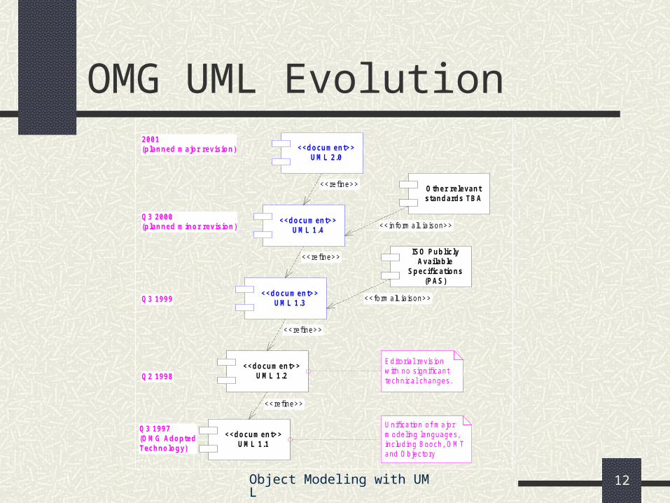
OMG UML Evolution
<<docum ent>>UM L 1.1
<<docum ent>>UM L 1.2
<<docum ent>>UM L 1.3
<<refine>>
<<docum ent>>UM L 1.4
<<docum ent>>UM L 2.0
<<refine>>
<<refine>>
<<refine>>
Q3 1997(OM G AdoptedTechnology)
Q2 1998
Q3 1999
Q3 2000(planned m inor revision)
2001(planned m ajor revision)
Editorial revisionwith no significanttechnical changes.
ISO PubliclyAvailable
Specifications(PAS)
Other relevantstandards TBA
<<inform alLiaison>>
<<form alLiaison>>
Unification of m ajorm odeling languages,including Booch, OMTand Objectory
Object Modeling with UML 13
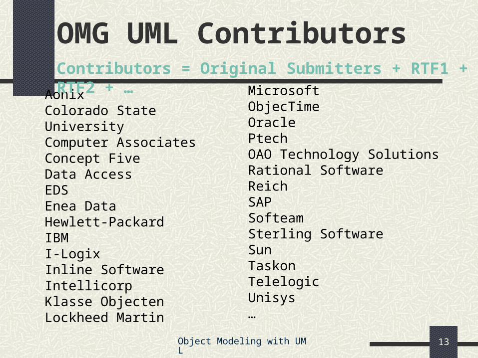
OMG UML Contributors
AonixColorado State UniversityComputer AssociatesConcept FiveData AccessEDSEnea DataHewlett-Packard IBMI-LogixInline SoftwareIntellicorpKlasse ObjectenLockheed Martin
Contributors = Original Submitters + RTF1 + RTF2 + …
Object Modeling with UML 14
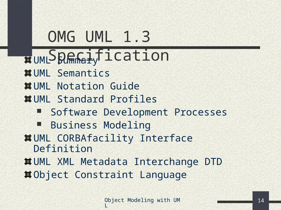
OMG UML 1.3 Specification
UML SummaryUML SemanticsUML Notation GuideUML Standard Profiles Software Development Processes Business Modeling
UML CORBAfacility Interface DefinitionUML XML Metadata Interchange DTDObject Constraint Language
Object Modeling with UML 15
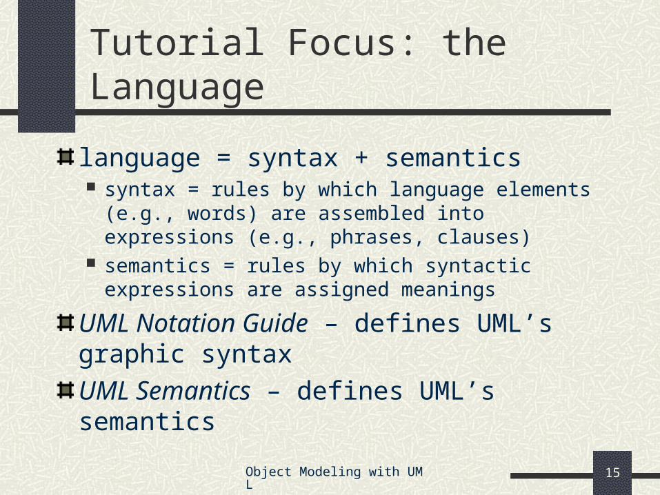
Tutorial Focus: the Language
language = syntax + semantics syntax = rules by which language elements (e.g.,
words) are assembled into expressions (e.g., phrases, clauses)
semantics = rules by which syntactic expressions are assigned meanings
UML Notation Guide – defines UML’s graphic syntax
UML Semantics – defines UML’s semantics
Object Modeling with UML 16
Building blocks
Well-formedness rules
Foundation Concepts
Object Modeling with UML 17
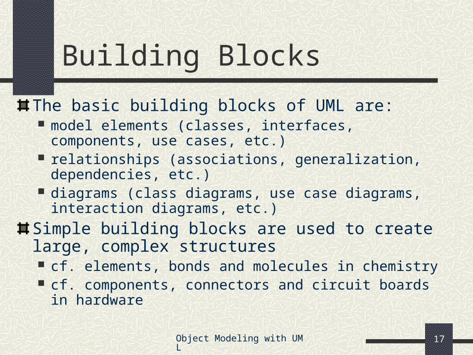
The basic building blocks of UML are: model elements (classes, interfaces, components, use cases,
etc.) relationships (associations, generalization, dependencies, etc.) diagrams (class diagrams, use case diagrams, interaction
diagrams, etc.)
Simple building blocks are used to create large, complex structures cf. elements, bonds and molecules in chemistry cf. components, connectors and circuit boards in hardware
Building Blocks
Object Modeling with UML 18
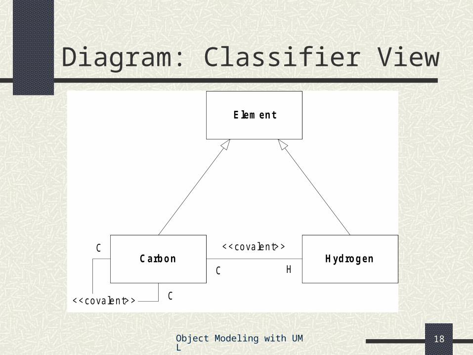
Diagram: Classifier View
Elem ent
Carbon Hydrogen
<<covalent>>
<<covalent>>C
C
C H
Object Modeling with UML 19
Diagram: Instance View
:Carbon :Carbon
:Hydrogen
:Hydrogen
:Hydrogen
:Hydrogen
:Hydrogen:Hydrogen
Object Modeling with UML 20
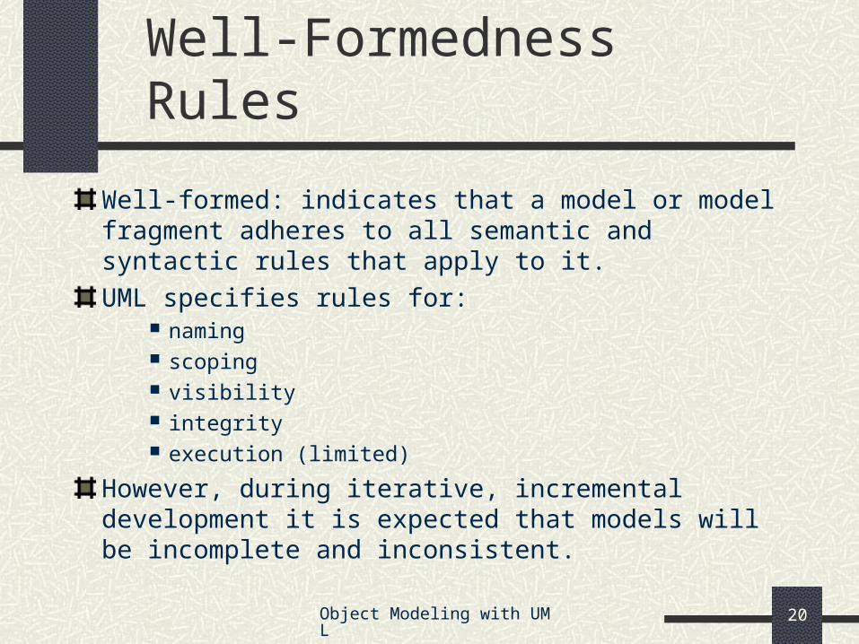
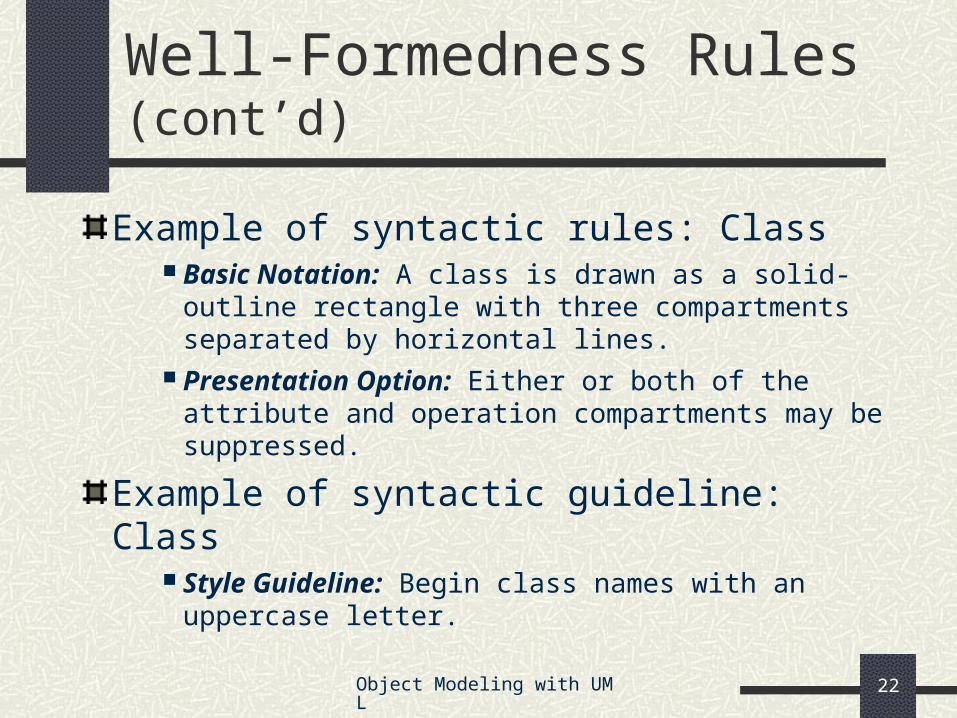
Well-Formedness Rules
Well-formed: indicates that a model or model fragment adheres to all semantic and syntactic rules that apply to it.
Example of syntactic rules: Class Basic Notation: A class is drawn as a solid-outline
rectangle with three compartments separated by horizontal lines.
Presentation Option: Either or both of the attribute and operation compartments may be suppressed.
Example of syntactic guideline: Class Style Guideline: Begin class names with an
uppercase letter.
Object Modeling with UML 23
Unifying Concepts
classifier-instance dichotomy e.g., an object is an instance of a class OR
a class is the classifier of an object
specification-realization dichotomy e.g., an interface is a specification of a class OR
a class is a realization of an interface
analysis-time vs. design-time vs. run-time modeling phases (“process creep”) usage guidelines suggested, not enforced
Object Modeling with UML 24
Language Architecture
Metamodel architecture
Package structure
Object Modeling with UML 25
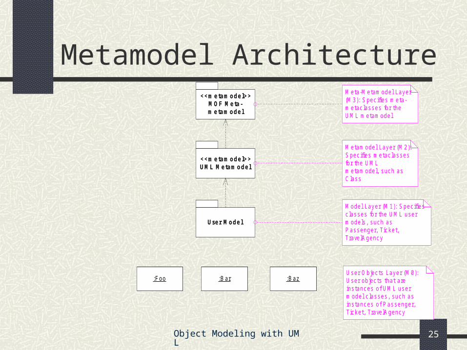
Metamodel Architecture<<m e ta m ode l>>
MOF Me ta -m e ta m ode l
<<m e ta m ode l>>UML Me ta m ode l
Use r Mode l
:Foo
Meta-Metamodel Layer(M3): Spec ifies meta-metac lasses for theUML metamodel
Metamodel Layer (M2):Spec ifies metac lassesfor the UMLmetamodel, such asClass
Model Layer (M1): Spec ifiesc lasses for the UML usermodels , such asPassenger, Ticket,TravelAgency
User Objects Layer (M0):User objects that areins tances of UML usermodel c lasses, such asinstances of Passenger,Ticket, TravelAgency
:Bar :Baz
Object Modeling with UML 26
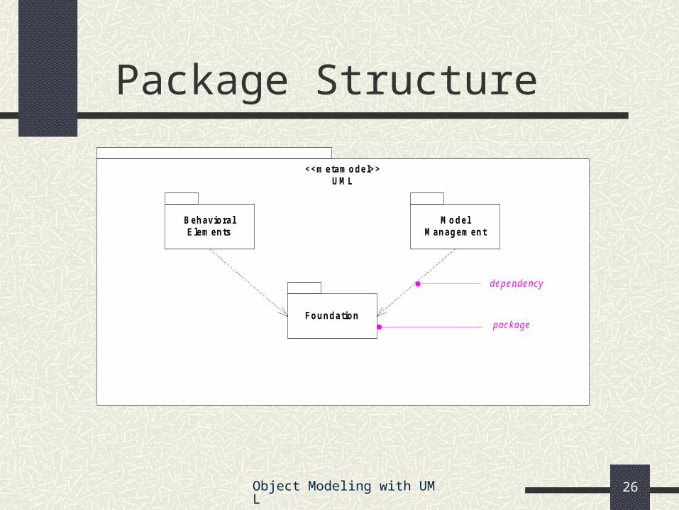
Package Structure
<<m etam odel>>UM L
M odelM anagem ent
BehavioralE lem ents
Foundationpackage
dependency
Object Modeling with UML 27
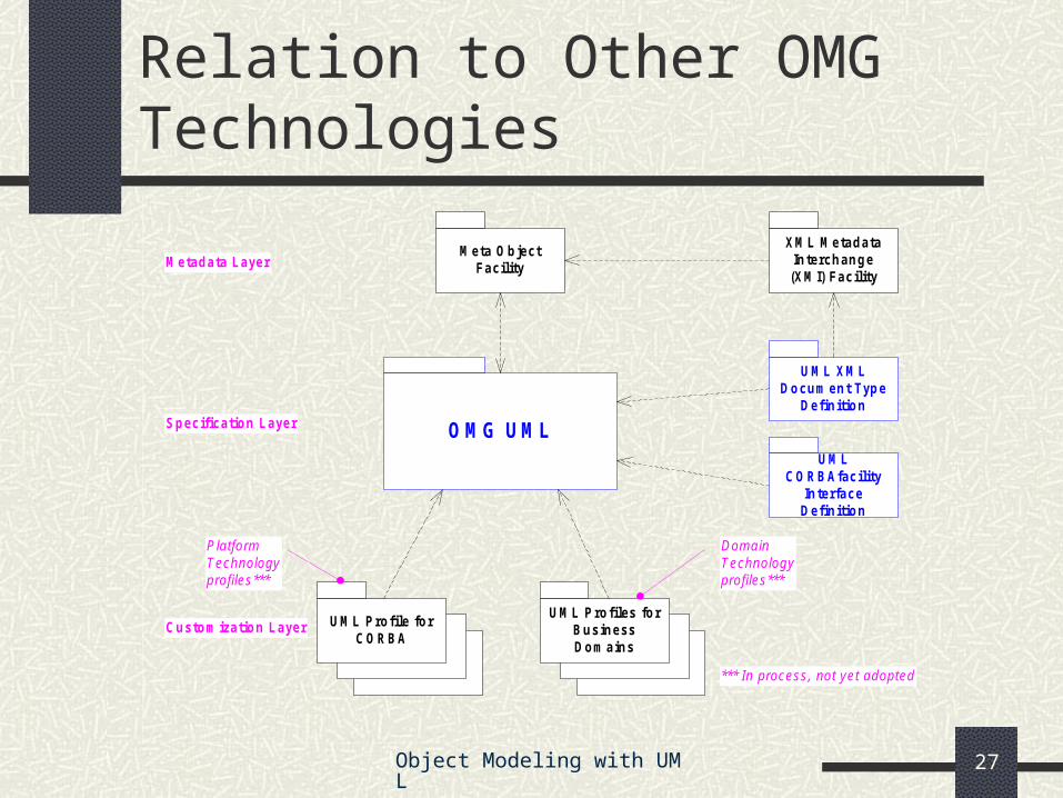
Relation to Other OMG Technologies
OMG UML
UM L XM LDocum ent Type
Definition
XM L M etadataInterchange
(XM I) Facility
UM L Profile forCORBA
UM L Profiles forBusinessDom ains
M eta ObjectFacility
Specification Layer
M etadata Layer
Custom ization Layer
PlatformTechnologyprofiles***
DomainTechnologyprofiles***
*** In process, not yet adopted
UM LCORBAfacility
InterfaceDefinition
Object Modeling with UML 28
Structural Modeling
What is structural modeling?
Core concepts
Diagram tour
When to model structure
Modeling tips
Example: Interface-based design
Object Modeling with UML 29
What is structural modeling?
Structural model: a view of an system that emphasizes the structure of the objects, including their classifiers, relationships, attributes and operations.
Object Modeling with UML 30
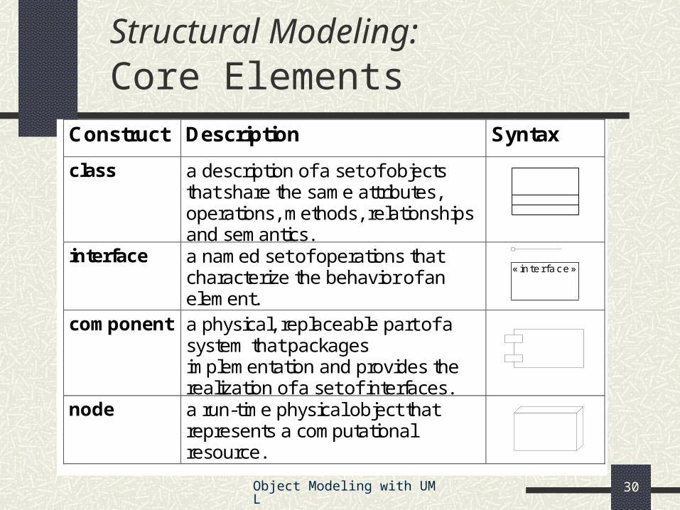
Structural Modeling: Core Elements
Construct Description Syntax
class a description of a set of objects that share the same attributes, operations, methods, relationships and semantics.
interface a named set of operations that characterize the behavior of an element.
component a physical, replaceable part of a system that packages implementation and provides the realization of a set of interfaces.
node a run-time physical object that represents a computational resource.
«interface»
Object Modeling with UML 31
Structural Modeling: Core Elements (cont’d)
Construct Description Syntax
constraint¹ a semantic condition or restriction.
{constra in t}
¹ An extension mechanism useful for specifying structural elements.
Object Modeling with UML 32
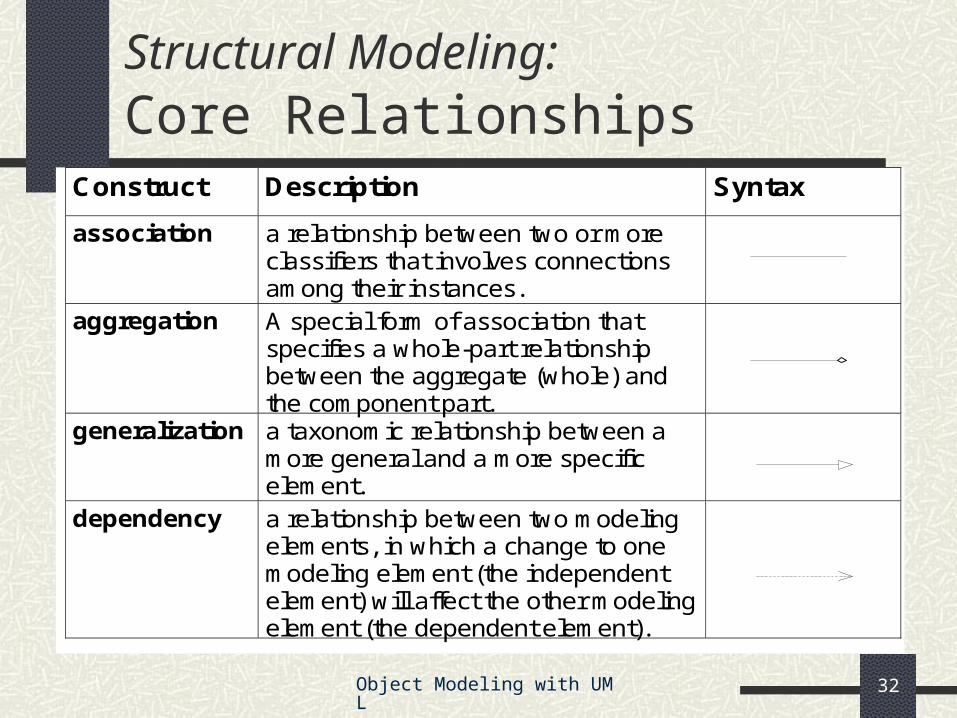
Construct Description Syntax
association a relationship between two or more classifiers that involves connections among their instances.
aggregation A special form of association that specifies a whole-part relationship between the aggregate (whole) and the component part.
generalization a taxonomic relationship between a more general and a more specific element.
dependency a relationship between two modeling elements, in which a change to one modeling element (the independent element) will affect the other modeling element (the dependent element).
Structural Modeling: Core Relationships
Object Modeling with UML 33
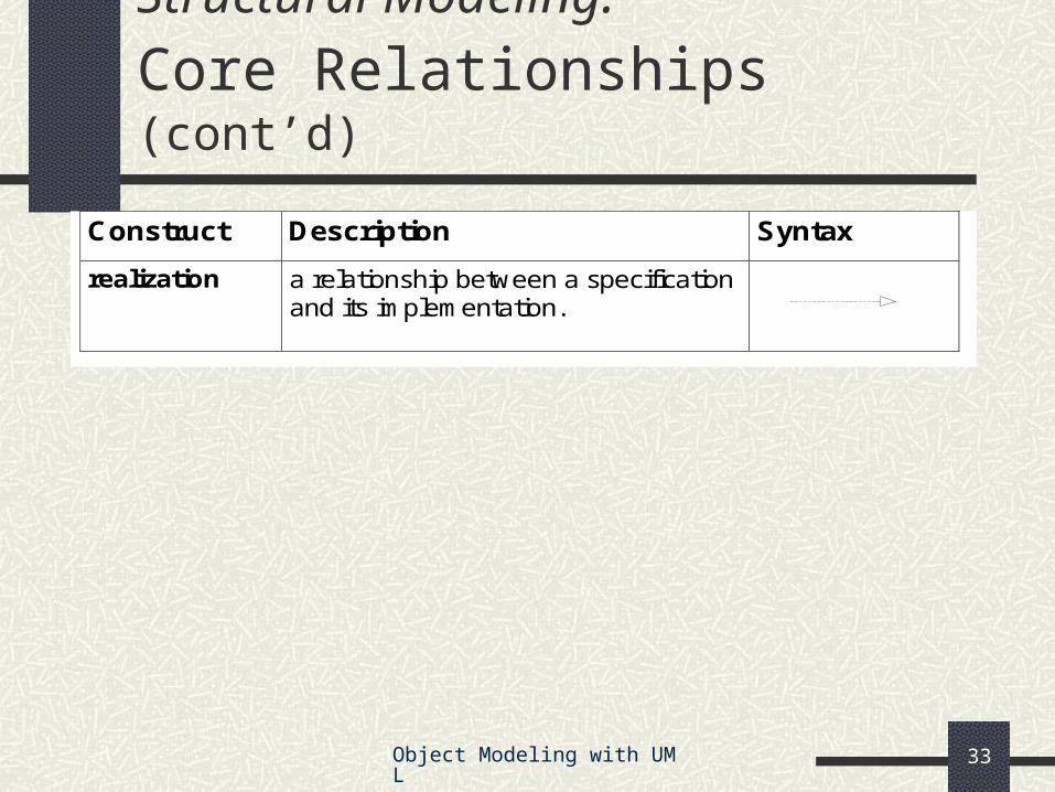
Construct Description Syntax
realization a relationship between a specification and its implementation.
Structural Modeling: Core Relationships (cont’d)
Object Modeling with UML 34
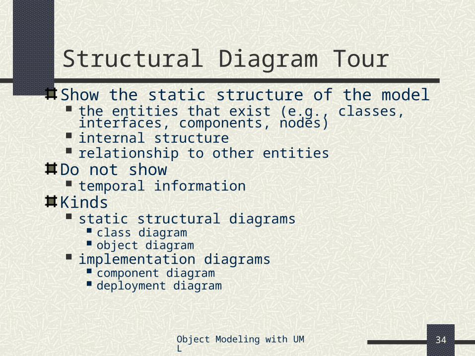
Show the static structure of the model the entities that exist (e.g., classes, interfaces,
components, nodes) internal structure relationship to other entities
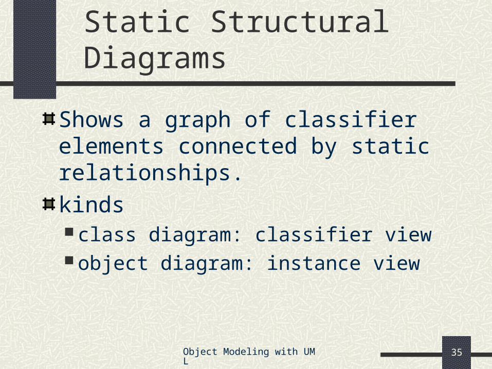
Shows a graph of classifier elements connected by static relationships.
kinds class diagram: classifier view object diagram: instance view
Object Modeling with UML 36
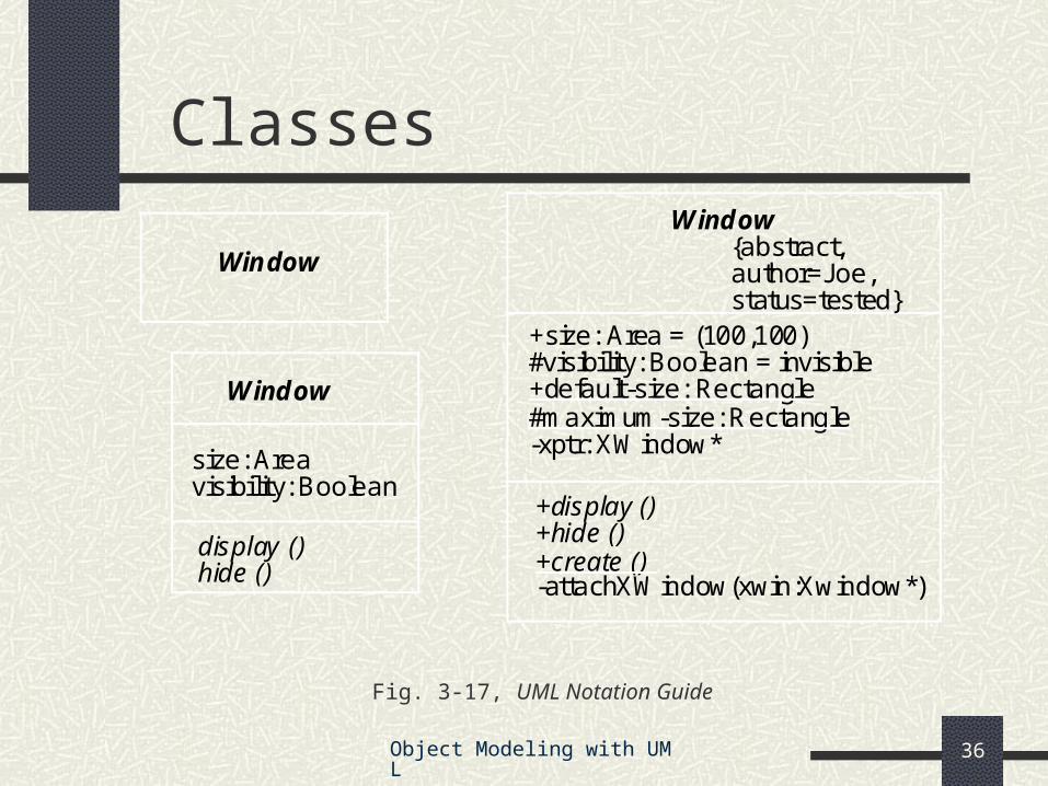
Classes
Fig. 3-17, UML Notation Guide
Window
display ()
size: Areavisibility: Boolean
hide ()
Window
Window
+default-size: Rectangle#maximum-size: Rectangle
+create ()
+display ()
+size: Area = (100,100)#visibility: Boolean = invisible
+hide ()
-xptr: XWindow*
-attachXWindow(xwin:Xwindow*)
{abstract,author=Joe,status=tested}
Object Modeling with UML 37
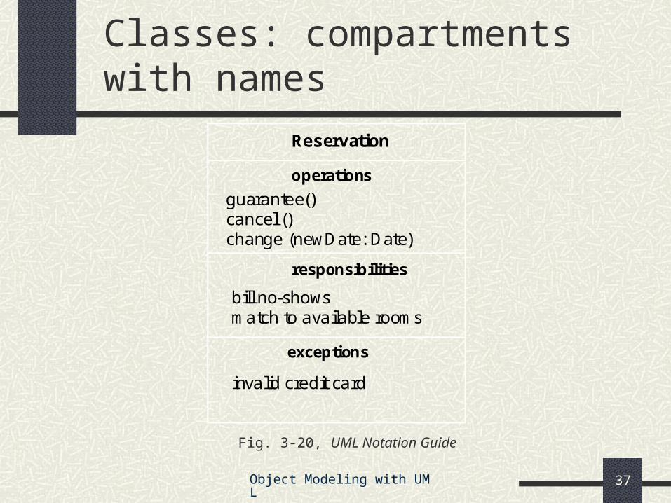
Classes: compartments with names
Fig. 3-20, UML Notation Guide
bill no-shows
Reservation
operations
guarantee()cancel ()change (newDate: Date)
responsibilities
match to available rooms
exceptions
invalid credit card
Object Modeling with UML 38
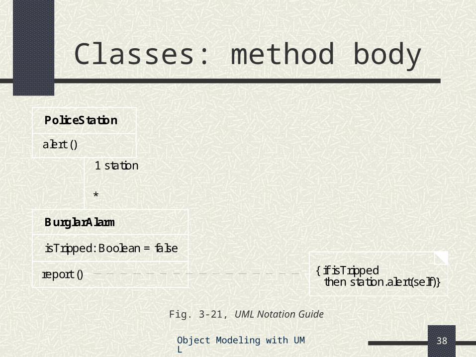
Classes: method body
Fig. 3-21, UML Notation Guide
report ()
BurglarAlarm
isTripped: Boolean = false
PoliceStation
1 station
*
{ if isTrippedthen station.alert(self)}
alert ()
Object Modeling with UML 39
Interfaces
Fig. 3-24, UML Notation Guide
HashTable
Hashable
Comparable
String. . .
isEqual(String):Booleanhash():Integer
contents*
Comparable«interface»
isEqual(String):Booleanhash():Integer
. . .
«use»
Object Modeling with UML 40
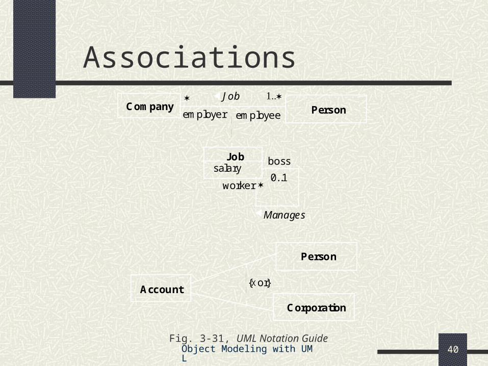
Associations
Fig. 3-31, UML Notation Guide
Person
Manages
JobCompany
boss
worker
employeeemployer
0..1
Job
Account
Person
Corporation
{Xor}
salary
Object Modeling with UML 41
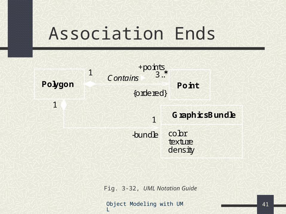
Association Ends
Fig. 3-32, UML Notation Guide
Polygon PointContains
{ordered}
3..1
GraphicsBundle
colortexturedensity
1
1
-bundle
+points
Object Modeling with UML 42
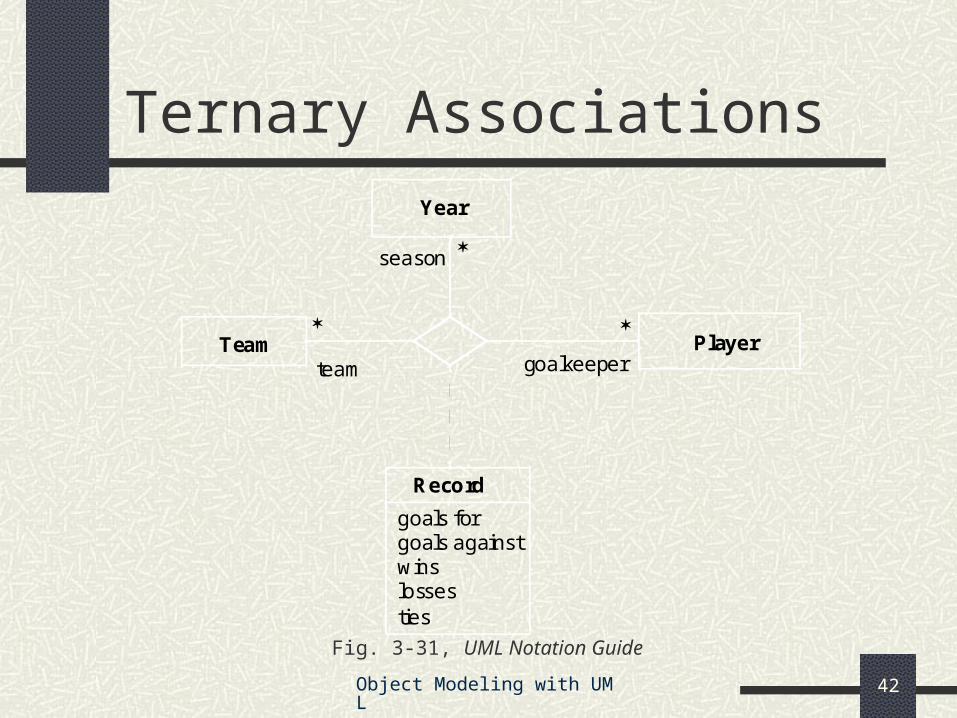
Fig. 3-31, UML Notation Guide
PlayerTeam
Year
Record
goals forgoals againstwinslosses
goalkeeper
season
team
ties
Ternary Associations
Object Modeling with UML 43
Composition
Fig. 3-36, UML Notation Guide
Window
scrollbar [2]: Slidertitle: Headerbody: Panel
Window
scrollbar title body
Header Panel
2 1 1
Slider
111
Object Modeling with UML 44
Composition
Fig. 3-36, UML Notation Guide
scrollbar:Slider
Window
2
title:Header1
body:Panel1
Object Modeling with UML 45
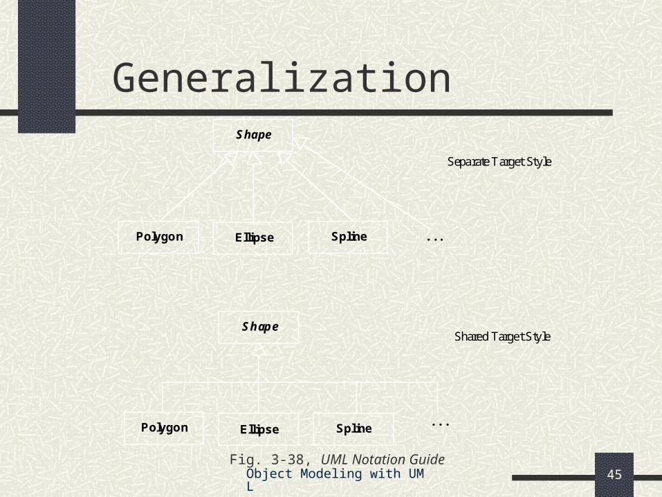
Generalization
Fig. 3-38, UML Notation Guide
Shape
SplineEllipsePolygon
Shape
SplineEllipsePolygon
Shared Target Style
Separate Target Style
. . .
. . .
Object Modeling with UML 46
Generalization
Fig. 3-39, UML Notation Guide
Vehicle
WindPoweredVehicle
MotorPoweredVehicle
LandVehicle
WaterVehicle
venue
venuepowerpower
SailboatTruck
{overlapping} {overlapping}
Object Modeling with UML 47
Dependencies
Fig. 3-41, UML Notation Guide
«friend»ClassA ClassB
ClassC
«instantiate»
«call»
ClassD
operationZ()«friend»
ClassD ClassE
«refine»ClassC combines
two logical classes
Object Modeling with UML 48
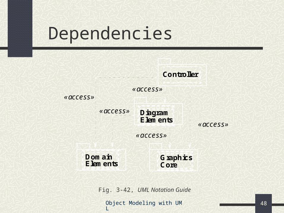
Dependencies
Fig. 3-42, UML Notation Guide
Controller
DiagramElements
DomainElements
GraphicsCore
«access»
«access»
«access»
«access»
«access»
Object Modeling with UML 49
Objects
Fig. 3-29, UML Notation Guide
triangle: Polygon
center = (0,0)vertices = ((0,0),(4,0),(4,3))borderColor = blackfillColor = white
triangle: Polygon
triangle
:Polygon
scheduler
Object Modeling with UML 50
Composite objects
Fig. 3-30, UML Notation Guide
horizontalBar:ScrollBar
verticalBar:ScrollBar
awindow : Window
surface:Pane
title:TitleBar
moves
moves
Object Modeling with UML 51
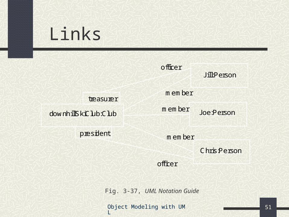
Links
Fig. 3-37, UML Notation Guide
downhillSkiClub:Club Joe:Person
Jill:Person
Chris:Person
member
member
member
treasurer
officer
president
officer
Object Modeling with UML 52
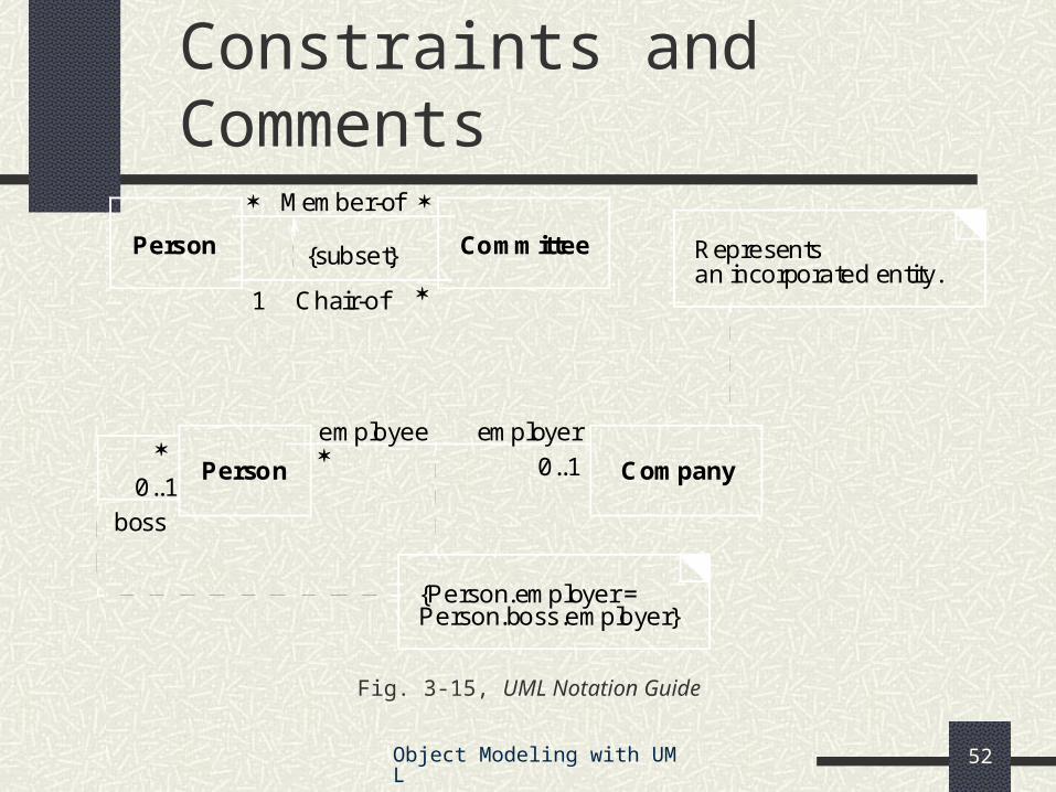
Constraints and Comments
Fig. 3-15, UML Notation Guide
Member-of
Chair-of
{subset}Person Committee
Person Company
boss
{Person.employer =Person.boss.employer}
employeremployee
0..1
0..1
1
Representsan incorporated entity.
Object Modeling with UML 53
Implementation Diagrams
Show aspects of model implementation, including source code structure and run-time implementation structure
Kinds component diagram deployment diagram
Object Modeling with UML 54
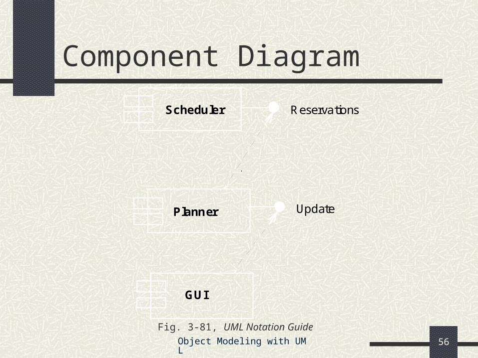
Shows the dependencies among software components
Components include source code components binary code components executable components
Component Diagram
Object Modeling with UML 55
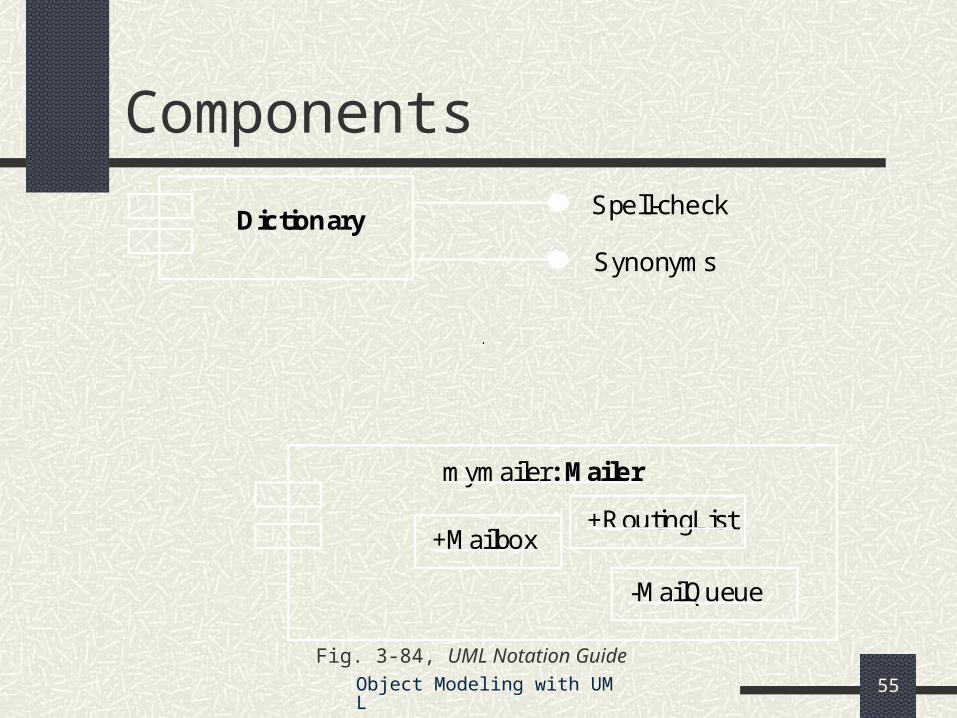
Fig. 3-84, UML Notation Guide
Components
DictionarySpell-check
Synonyms
mymailer: Mailer
+Mailbox+RoutingList
-MailQueue
Object Modeling with UML 56
Fig. 3-81, UML Notation Guide
Component Diagram
Planner
Scheduler
GUI
Reservations
Update
Object Modeling with UML 57
Deployment Diagram
Shows the configuration of run-time processing elements and the software components, processes and objects that live on them
Deployment diagrams may be used to show which components may run on which nodes
Object Modeling with UML 58
Deployment Diagram
Fig. 3-82, UML Notation Guide
AdminServer:HostMachine
Joe’sMachine:PC
:Scheduler reservations
:Planner
«database»meetingsDB
Object Modeling with UML 59
Deployment Diagram (cont’d)
Fig. 3-83, UML Notation Guide
Node1
Node2
«cluster»
x y
«cluster»
x y
«become»
«database»
w z
Object Modeling with UML 60
When to model structure
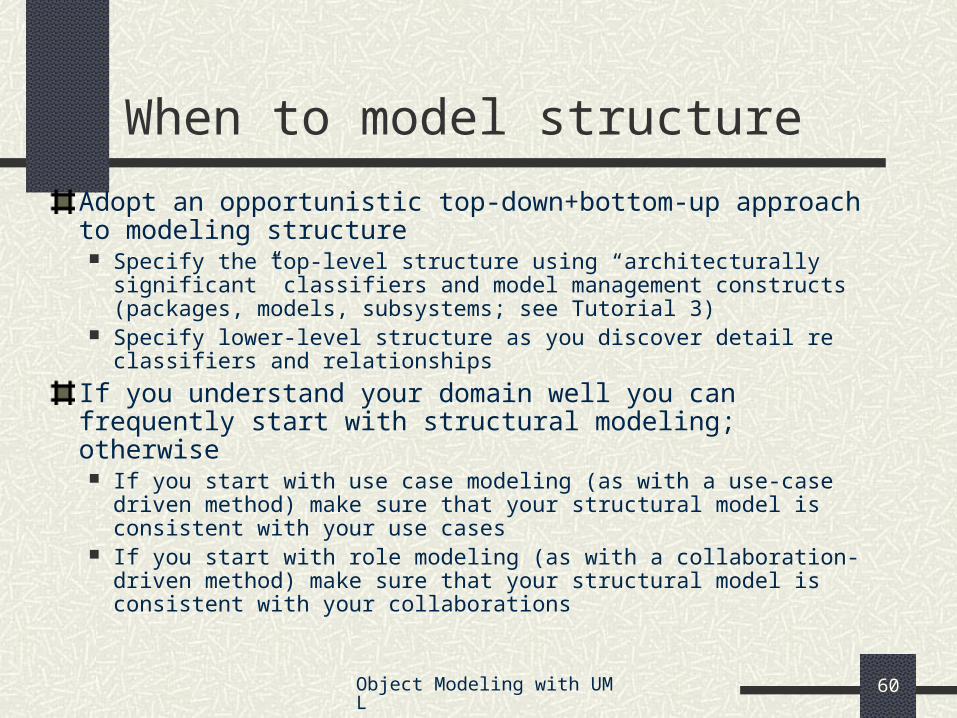
Adopt an opportunistic top-down+bottom-up approach to modeling structure Specify the top-level structure using “architecturally significant”
classifiers and model management constructs (packages, models, subsystems; see Tutorial 3)
Specify lower-level structure as you discover detail re classifiers and relationships
If you understand your domain well you can frequently start with structural modeling; otherwise If you start with use case modeling (as with a use-case driven method)
make sure that your structural model is consistent with your use cases If you start with role modeling (as with a collaboration-driven method)
make sure that your structural model is consistent with your collaborations
Object Modeling with UML 61
Structural Modeling Tips
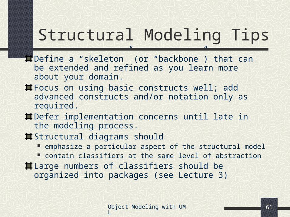
Define a “skeleton” (or “backbone”) that can be extended and refined as you learn more about your domain.Focus on using basic constructs well; add advanced constructs and/or notation only as required.Defer implementation concerns until late in the modeling process.Structural diagrams should emphasize a particular aspect of the structural model contain classifiers at the same level of abstraction
Large numbers of classifiers should be organized into packages (see Lecture 3)
Object Modeling with UML 62
Example: Interface-based designmodule POS{ typedef long POSId; typedef string Barcode;
Chapter to appear, CORBA Fundamentals and Programming (2d ed.), [Siegel 00]
Object Modeling with UML 64
Use Case Modeling
What is use case modeling?
Core concepts
Diagram tour
When to model use cases
Modeling tips
Example: Online HR System
Object Modeling with UML 65
What is use case modeling?
use case model: a view of a system that emphasizes the behavior as it appears to outside users. A use case model partitions system functionality into transactions (‘use cases’) that are meaningful to users (‘actors’).
Object Modeling with UML 66
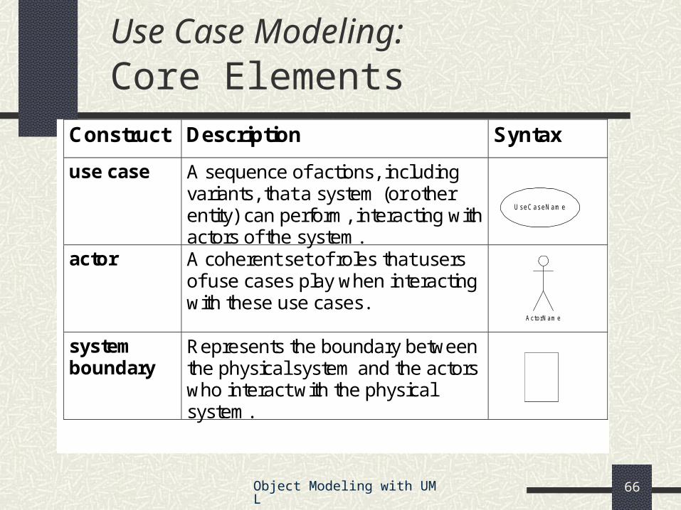
Use Case Modeling: Core Elements
Construct Description Syntax
use case A sequence of actions, including variants, that a system (or other entity) can perform, interacting with actors of the system.
actor A coherent set of roles that users of use cases play when interacting with these use cases.
system boundary
Represents the boundary between the physical system and the actors who interact with the physical system.
UseCaseNam e
ActorNam e
Object Modeling with UML 67
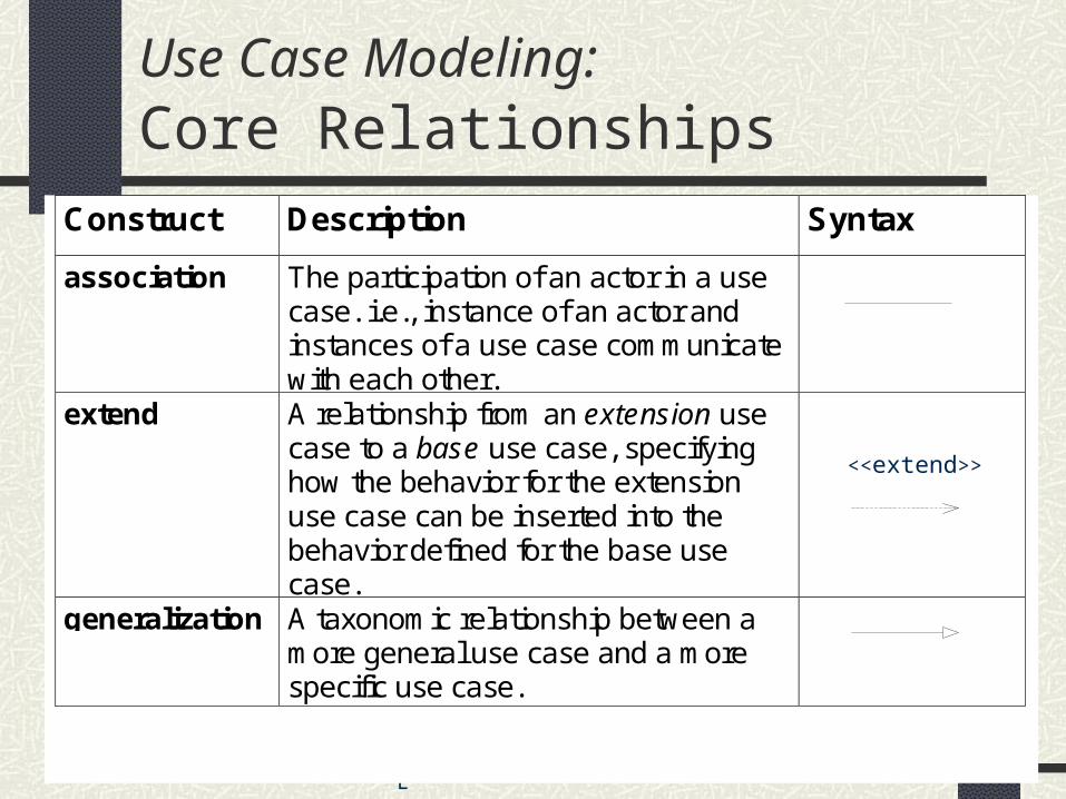
Construct Description Syntax
association The participation of an actor in a usecase. i.e., instance of an actor andinstances of a use case communicatewith each other.
extend A relationship from an extension usecase to a base use case, specifyinghow the behavior for the extensionuse case can be inserted into thebehavior defined for the base usecase.
generalization A taxonomic relationship between amore general use case and a morespecific use case.
Use Case Modeling: Core Relationships
<<extend>>
Object Modeling with UML 68
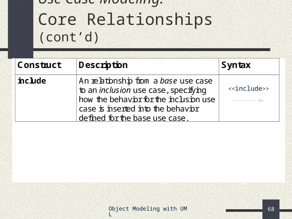
Construct Description Syntax
include An relationship from a base use caseto an inclusion use case, specifyinghow the behavior for the inclusion usecase is inserted into the behaviordefined for the base use case.
Use Case Modeling: Core Relationships (cont’d)
<<include>>
Object Modeling with UML 69
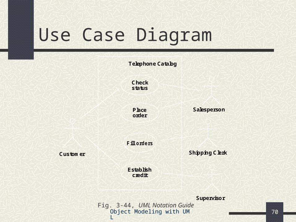
Shows use cases, actor and their relationships
Use case internals can be specified by text and/or interaction diagrams (see Lecture 2)Kinds use case diagram use case description
Use Case Diagram Tour
Object Modeling with UML 70Fig. 3-44, UML Notation Guide
Customer
Supervisor
SalespersonPlace
Establishcredit
Check
Telephone Catalog
F ill orde rs
Shipping Clerk
status
order
Use Case Diagram
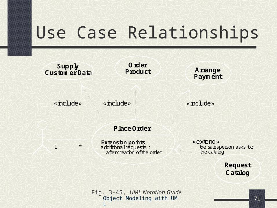
Object Modeling with UML 71Fig. 3-45, UML Notation Guide
Use Case Relationships
additional requests :
OrderProduct
SupplyArrange
«include»«include»«include»
RequestCatalog
«extend»Extension points
PaymentCustomer Data
after creation of the order
Place Order
1 * the salesperson asks forthe catalog
Object Modeling with UML 72Fig. 3-46, UML Notation Guide
Traveler has logged on to the system and selected ‘change flight itinerary’ option
Basic course System retrieves traveler’s account and flight itinerary from client account database System asks traveler to select itinerary segment she wants to change; traveler selects itinerary segment. System asks traveler for new departure and destination information; traveler provides information. If flights are available then … System displays transaction summary.
Alternative courses If no flights are available then …
Object Modeling with UML 74
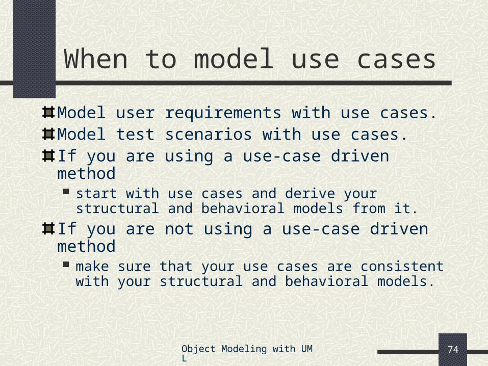
When to model use cases
Model user requirements with use cases.Model test scenarios with use cases.If you are using a use-case driven method start with use cases and derive your structural and
behavioral models from it.
If you are not using a use-case driven method make sure that your use cases are consistent with your
structural and behavioral models.
Object Modeling with UML 75
Use Case Modeling TipsMake sure that each use case describes a significant chunk of system usage that is understandable by both domain experts and programmersWhen defining use cases in text, use nouns and verbs accurately and consistently to help derive objects and messages for interaction diagrams (see Lecture 2)Factor out common usages that are required by multiple use cases If the usage is required use <<include>> If the base use case is complete and the usage may be optional, consider
use <<extend>>
A use case diagram should contain only use cases at the same level of abstraction include only actors who are required
Large numbers of use cases should be organized into packages (see Lecture 3)
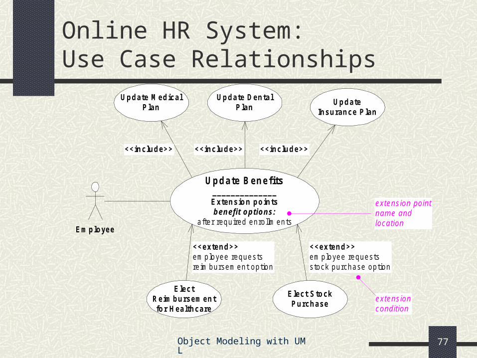
<<extend>>em ployee requestsreim bursem ent option
extensioncondition
extension pointname andlocation
Object Modeling with UML 78
Online HR System: Update Benefits Use Case
Actors: employee, employee account db, healthcare plan system, insurance plan systemPreconditions:
Employee has logged on to the system and selected ‘update benefits’ option
Basic course System retrieves employee account from employee account db System asks employee to select medical plan type; include Update Medical Plan. System asks employee to select dental plan type; include Update Dental Plan. …
Alternative courses If health plan is not available in the employee’s area the employee is informed and asked to select another plan...
Object Modeling with UML 79
Wrap Up
Ideas to take away
Preview of next tutorial
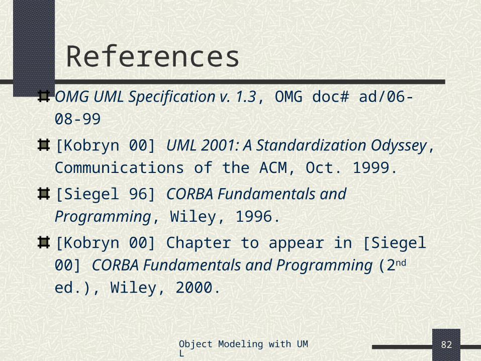
References
Further info
Object Modeling with UML 80
UML is effective for modeling large, complex software systemsIt is simple to learn for most developers, but provides advanced features for expert analysts, designers and architectsIt can specify systems in an implementation-independent manner10-20% of the constructs are used 80-90% of the timeStructural modeling specifies a skeleton that can be refined and extended with additional structure and behaviorUse case modeling specifies the functional requirements of system in an object-oriented manner