30
Object-Oriented Analysis and Design CHAPTERS 16: UML CLASS DIAGRAMS 1
| Date post: | 24-Dec-2015 |
| Category: |
Documents |
| Upload: | sherman-pope |
| View: | 221 times |
| Download: | 0 times |
1
Object-Oriented Analysis and DesignCHAPTERS 16: UML CLASS DIAGRAMS
2
What will we learn?UML Class Diagrams – What are they, how to create them
3
IntroductionUML provides the tools for creating general class diagrams, i.e. static object modeling, that can be used to create Domain Models or software class diagrams
We will look in more detail at the UML notation that can be used, irrespective of the perspective (conceptual or software class)
Note that UML provides a set of diagraming tools, most of which are optional to useStandardized diagram language, makes it easier to communicate designs
The next slide gives an overview of the concepts we will be discussing in this lecture
4
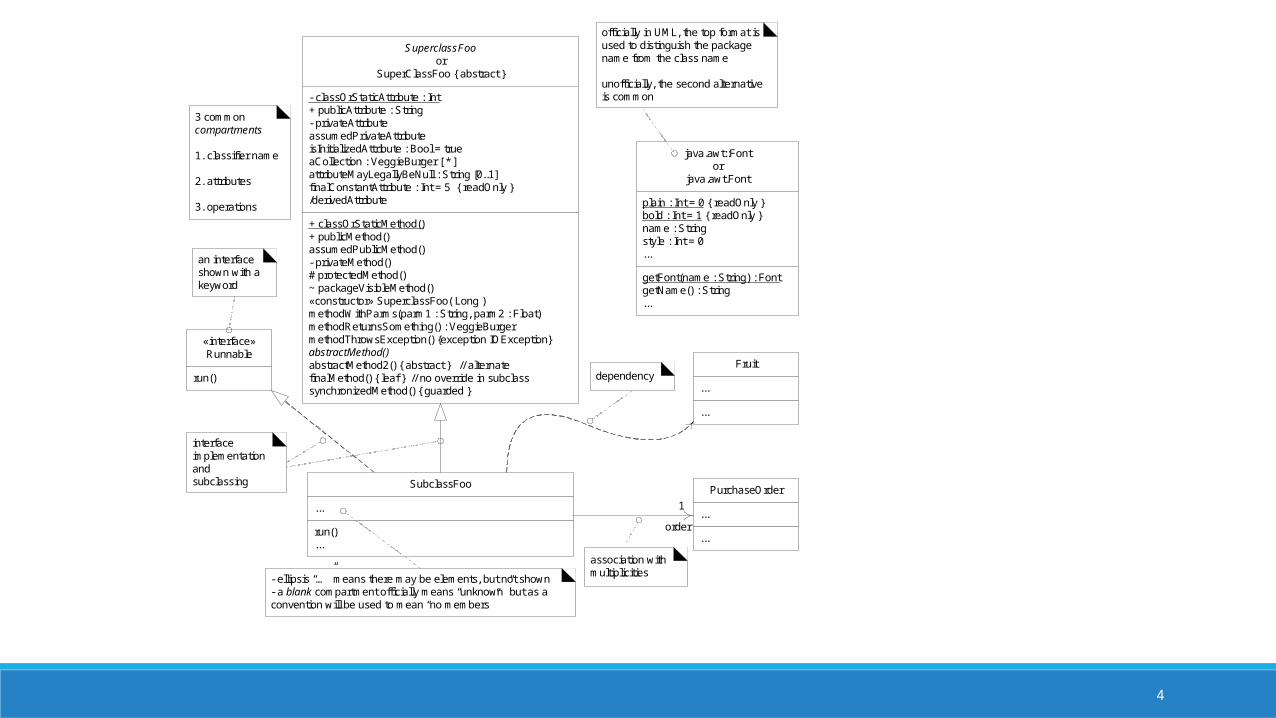
java.awt::Fontor
java.awt.Font
plain : Int = 0 { readOnly }bold : Int = 1 { readOnly }name : Stringstyle : Int = 0...
getFont(name : String) : FontgetName() : String...
«interface»Runnable
run()
- ellipsis “…” means there may be elements, but not shown- a blank compartment officially means “unknown” but as a convention will be used to mean “no members”
SubclassFoo
...
run()...
SuperclassFooor
SuperClassFoo { abstract }
- classOrStaticAttribute : Int+ publicAttribute : String- privateAttributeassumedPrivateAttributeisInitializedAttribute : Bool = trueaCollection : VeggieBurger [ * ]attributeMayLegallyBeNull : String [0..1] finalConstantAttribute : Int = 5 { readOnly }/derivedAttribute
+ classOrStaticMethod()+ publicMethod()assumedPublicMethod()- privateMethod()# protectedMethod()~ packageVisibleMethod()«constructor» SuperclassFoo( Long )methodWithParms(parm1 : String, parm2 : Float)methodReturnsSomething() : VeggieBurgermethodThrowsException() {exception IOException}abstractMethod()abstractMethod2() { abstract } // alternatefinalMethod() { leaf } // no override in subclasssynchronizedMethod() { guarded }
3 common compartments
1. classifier name
2. attributes
3. operations
interface implementation andsubclassing
Fruit
...
...
PurchaseOrder
...
...
1
association with multiplicities
dependency
officially in UML, the top format is used to distinguish the package name from the class name
unofficially, the second alternative is common
order
an interface shown with a keyword
5
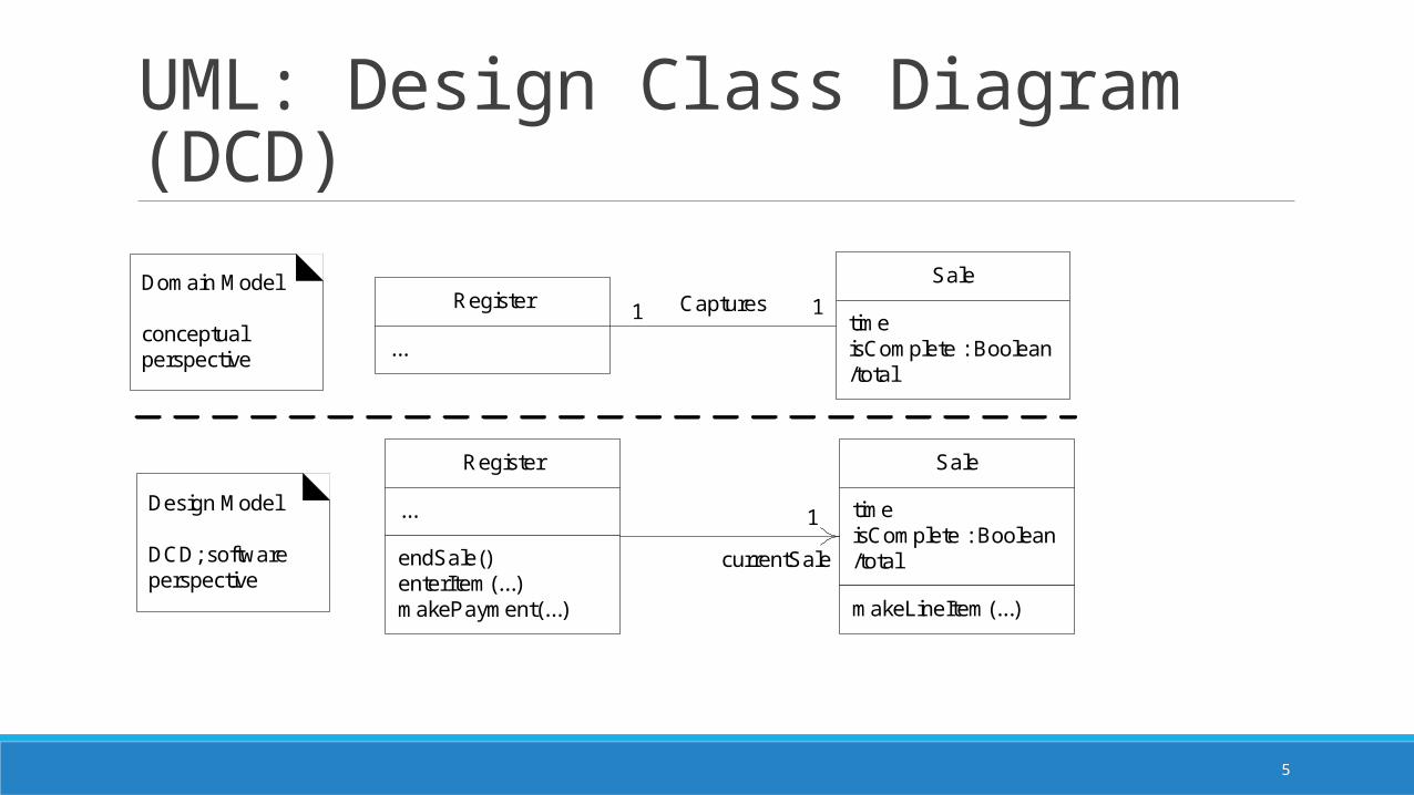
UML: Design Class Diagram (DCD)
Register
...
endSale()enterItem(...)makePayment(...)
Sale
timeisComplete : Boolean/total
makeLineItem(...)
Register
...
Sale
timeisComplete : Boolean/total
Captures
1
11Domain Model
conceptual perspective
Design Model
DCD; software perspective
currentSale
6
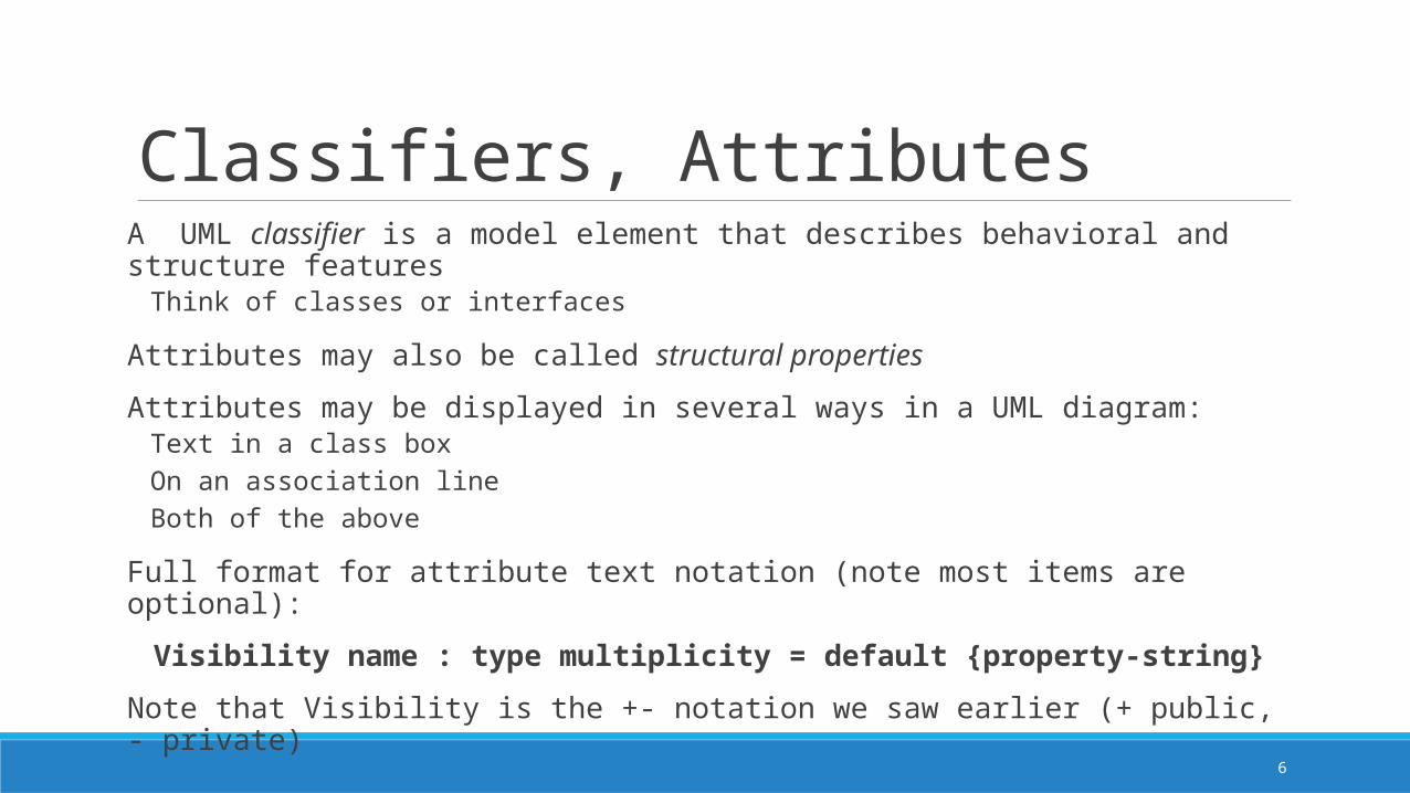
Classifiers, AttributesA UML classifier is a model element that describes behavioral and structure features
Think of classes or interfaces
Attributes may also be called structural properties
Attributes may be displayed in several ways in a UML diagram:Text in a class boxOn an association lineBoth of the above
Full format for attribute text notation (note most items are optional):
Visibility name : type multiplicity = default {property-string}
Note that Visibility is the +- notation we saw earlier (+ public, - private)
7
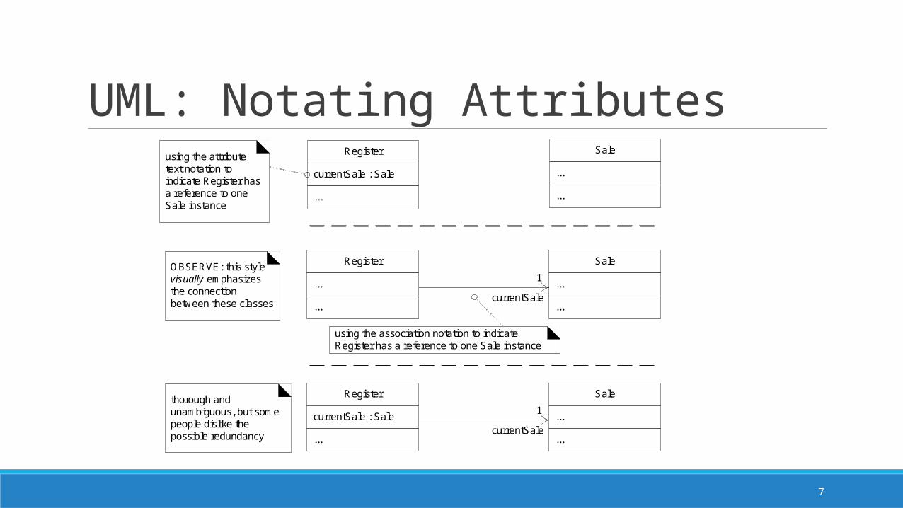
UML: Notating Attributes
Register
...
...
Sale
...
...
1
Register
currentSale : Sale
...
Sale
...
...
using the attribute text notation to indicate Register has a reference to one Sale instance
using the association notation to indicate Register has a reference to one Sale instance
OBSERVE: this style visually emphasizes the connection between these classes
currentSale
Register
currentSale : Sale
...
Sale
...
...
1thorough and unambiguous, but some people dislike the possible redundancy
currentSale

8
Attributes As AssociationsNotice that there are subtle differences between the conceptual perspective (Domain Model) and software perspective (Design Model) for attributes that are defined as associations
For DCDs, there is usually A navigability arrow A multiplicity at the target end, but not the sourceA role nameNo association name
9
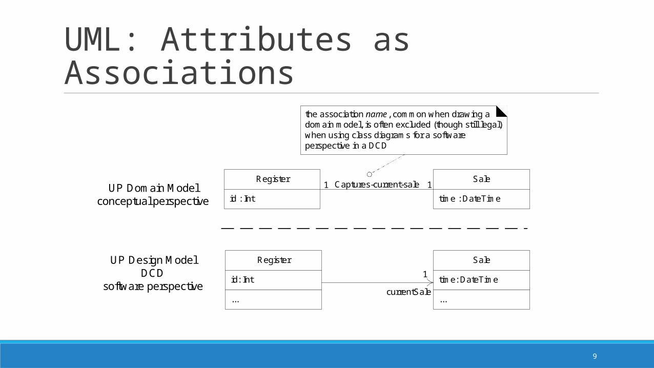
UML: Attributes as Associationsthe association name, common when drawing a domain model, is often excluded (though still legal) when using class diagrams for a software perspective in a DCD
Register
id: Int
...
Sale
time: DateTime
...
1
currentSale
Register
id : Int
Sale
time : DateTime
Captures-current-sale1 1UP Domain Modelconceptual perspective
UP Design ModelDCD
software perspective
10
Attributes: Text versus Associations
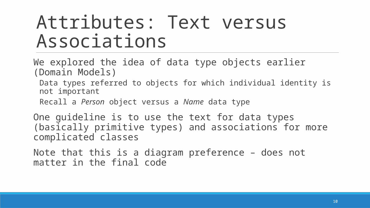
We explored the idea of data type objects earlier (Domain Models)Data types referred to objects for which individual identity is not importantRecall a Person object versus a Name data type
One guideline is to use the text for data types (basically primitive types) and associations for more complicated classes
Note that this is a diagram preference – does not matter in the final code
11
UML: Attributes as Associations
Register
id: Int
...
Sale
time: DateTime
...
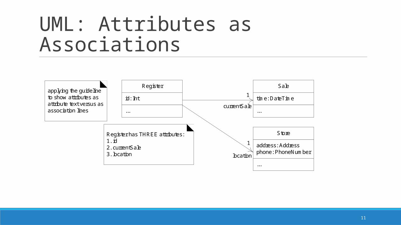
1applying the guideline to show attributes as attribute text versus as association lines
Store
address: Addressphone: PhoneNumber
...
1
Register has THREE attributes:1. id2. currentSale3. location
currentSale
location
12
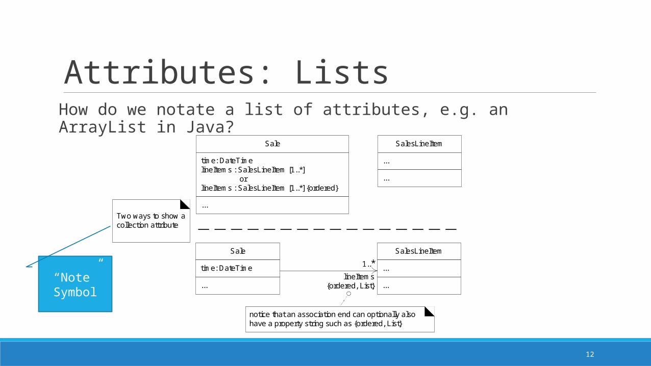
Attributes: ListsHow do we notate a list of attributes, e.g. an ArrayList in Java?
notice that an association end can optionally also have a property string such as {ordered, List}
Sale
time: DateTime
...
SalesLineItem
...
...
1..*lineItems
{ordered, List}
Sale
time: DateTimelineItems : SalesLineItem [1..*] orlineItems : SalesLineItem [1..*] {ordered}
...
SalesLineItem
...
...
Two ways to show a collection attribute
“Note” Symbol
13
Operations and MethodsOperations are usually displayed in the class box with the notation:
visibility name (parameter-list) {property-string}
Sometime a return-type is value is added
Assume public if no visibility is shown
An operation is a declaration (name, parameters, return type, exceptions list)
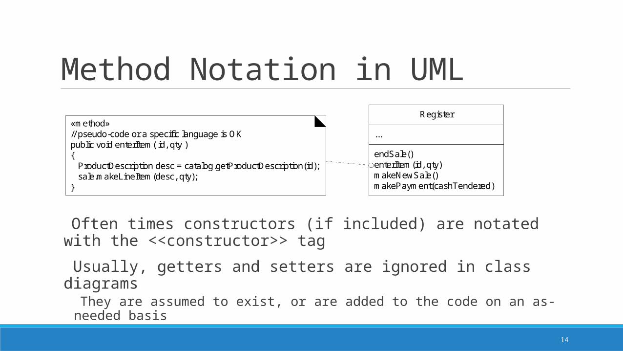
A method is an implementation of an operation in sequence diagrams, may show the details and sequence of messages In class diagram, usually include some pseudo-code in a note with the <<method>> tag
14
Method Notation in UMLRegister
...
endSale()enterItem(id, qty)makeNewSale()makePayment(cashTendered)
«method»// pseudo-code or a specific language is OKpublic void enterItem( id, qty ){ ProductDescription desc = catalog.getProductDescription(id); sale.makeLineItem(desc, qty);}
Often times constructors (if included) are notated with the <<constructor>> tag
Usually, getters and setters are ignored in class diagrams They are assumed to exist, or are added to the code on an as-needed basis

15
KeywordsKeywords are textual adornments used to categorize a model element – they provide some additional information about the element.
Usually notated <<keyword>>, and sometimes {keyword}
Some examples:<<actor>> - this entity is an actor<<interface>> - this entity is an interface{abstract} – this is an abstract element, it can’t be instantiated{ordered} – this set of objects is ordered, e.g. the ArrayList example shown earlier
16
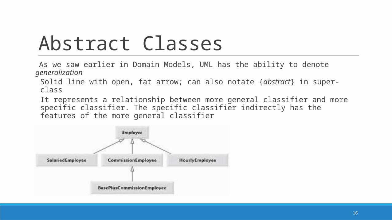
Abstract Classes As we saw earlier in Domain Models, UML has the ability to denote generalization
Solid line with open, fat arrow; can also notate {abstract} in super-classIt represents a relationship between more general classifier and more specific classifier. The specific classifier indirectly has the features of the more general classifier
17
Dependency in UMLIn UML, dependency lines can be used in any diagram, but they are especially common in class and package diagrams.
In UML, a general dependency relationship indicates that a client element (class, package, use case, etc.) has knowledge of a supplier element and that a change in the supplier could affect the client
Indicated by a dashed arrow from the client to the supplier
Note that we often associate elements with associations (e.g. super- and sub-classes as we just saw), so we do not need to add dependency arrows if an association already exists
Often used when a class has an attribute of another class type, or if one class sends a message to another class

18
Dependency in UMLGuideline: Use dependency in UML to depict global parameter variable, local variable, and static-method call to another class.
SalesLineItem
...
...
ProductDescription
...
...
1..*lineItems
Sale
...
updatePriceFor( ProductDescription )...
the Sale has parameter visibility to a ProductDescription, and thus some kind of dependency Public class Sale
{Public void updatePrice(ProductDescription description) { Money basePrice = description.getPrice(); …. } ….}

19
Dependency in UML
Public class Foo{Public void doX() { system.runFinalization(); …. } ….}
System
...
runFinalization()...
Foo
...
doX()...
the doX method invokes the runFinalization static method, and thus has a dependency on the System class
20
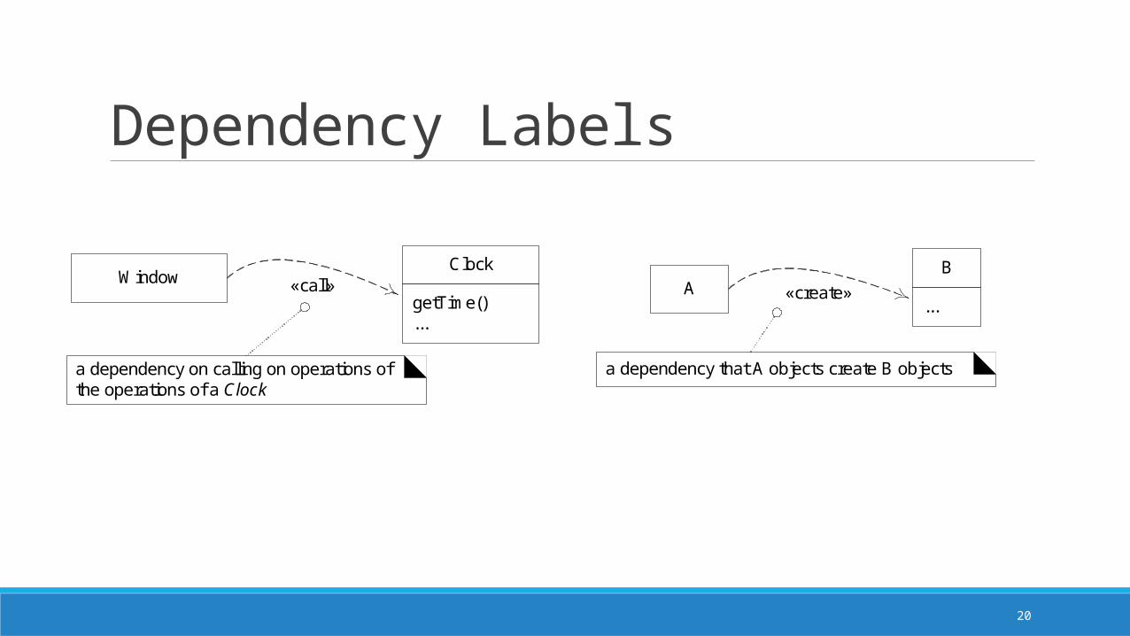
Dependency Labels
«call»Window
a dependency on calling on operations of the operations of a Clock
Clock
getTime()...
«create»A
a dependency that A objects create B objects
B
...
21
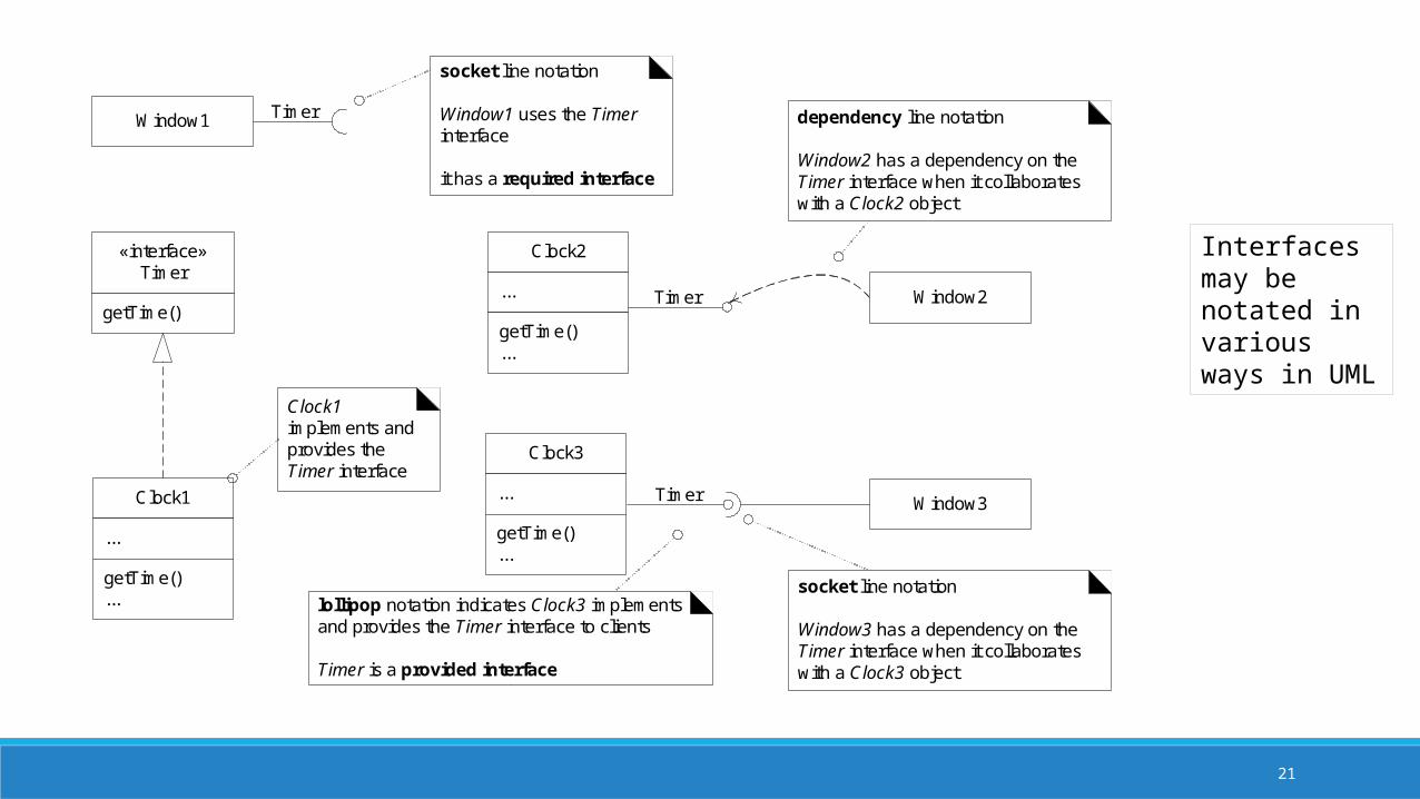
«interface»Timer
getTime()
Clock1
...
getTime()... lollipop notation indicates Clock3 implements
and provides the Timer interface to clients
Timer is a provided interface
Timer
Clock3
...
getTime()...
Window2
Window3
dependency line notation
Window2 has a dependency on the Timer interface when it collaborates with a Clock2 object
socket line notation
Window3 has a dependency on the Timer interface when it collaborates with a Clock3 object
Window1 Timer
socket line notation
Window1 uses the Timer interface
it has a required interface
Clock2
...
getTime()...
Clock1 implements and provides the Timer interface
Timer
Interfaces may be notated in various ways in UML

22
Composition and AggregationWe saw this earlier in Domain Models …
Composition is a whole-part relationship between model entities, such thatan instance of the part belongs to only one instance of the compositea part must belong to a compositethe composite is responsible for creating/deleting the parts. (So if the composite is destroyed, the parts are destroyed or become attached to another composite.)
Aggregation is a weaker form of composition, where the above requirements are not necessarily true
Aggregation does not imply ownership of the parts
Composition involves instantiating objects, aggregation involves pointers to other objects
23
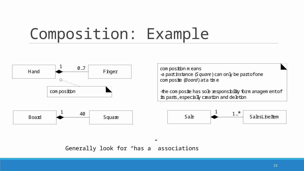
Composition: Example
Finger0..7
Hand
composition
1
Square40
Board1
SalesLineItem1..*
Sale1
composition means -a part instance (Square) can only be part of one composite (Board) at a time
-the composite has sole responsibility for management of its parts, especially creation and deletion
Generally look for “has a” associations
24
Constraints and Qualified Associations
In UML diagrams, a constraint is a restriction on an element
Usually indicated as some text between curly braces in the diagram, either in the class box or next to it
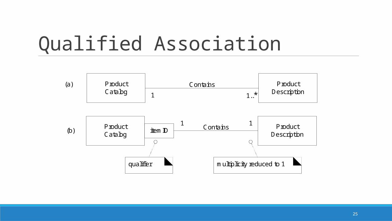
Associations may be qualified – this means the association may depend upon a particular key or parameter.
In the example on the next slide, we see a ProductCatalog that contains many ProductDescriptions. Each one is identified by an itemID.
Note the change in multiplicity in the UML diagram; the association is now related to a single instance, but it is understood that the there may be many associations
25
Qualified Association
ProductCatalog
ProductDescription
itemID Contains
ProductCatalog
ProductDescription
Contains
1..*
multiplicity reduced to 1
(a)
(b)
qualifier
1
11
26
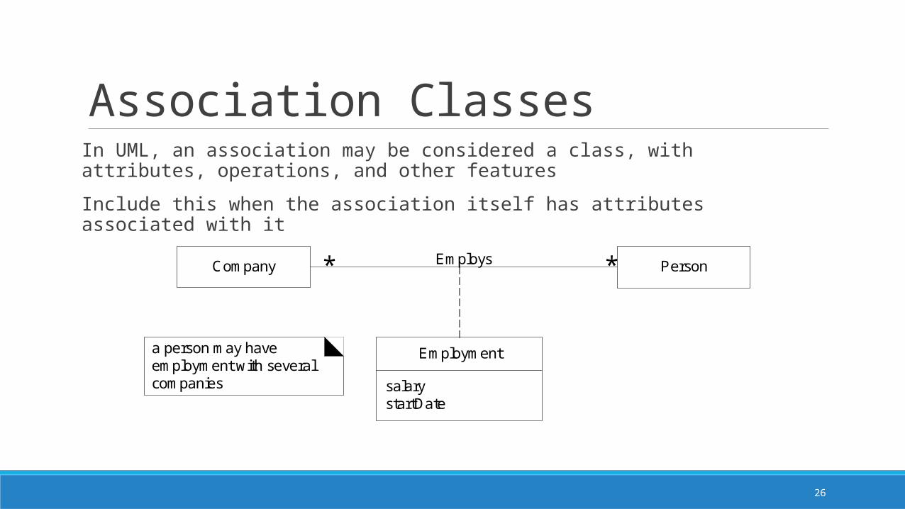
Association ClassesIn UML, an association may be considered a class, with attributes, operations, and other features
Include this when the association itself has attributes associated with it
salarystartDate
Employment
EmploysCompany Person**
a person may have employment with several companies
27

28
29
Takeaways from Chapter 16Understand the basics of reading UML diagrams, in particular with how they represent class diagrams.
30
Next …Chapter 15 – Creating interaction diagrams in UML


