Page 1
1
OBJECT TRACKING
By
ANIS SYAFIRIN BINTI EZHAR
FINAL PROJECT REPORT
Submitted to the Department of Electrical & Electronic Engineering
in Partial Fulfilment of the Requirements
for the Degree
Bachelor of Engineering (Hons)
(Electrical and Electronics Engineering)
Universiti Teknologi PETRONAS
Bandar Seri Iskandar
31750 Tronoh
Perak Darul Ridzuan
Copyright 2012
by
Anis Syafirin Binti Ezhar, 2012
Page 2
2
CERTIFICATION OF APPROVAL
OBJECT TRACKING
by
Anis Syafirin Binti Ezhar
A project dissertation submitted to the
Department of Electrical & Electronic Engineering
Universiti Teknologi PETRONAS
in partial fulfilment of the requirement for the
Bachelor of Engineering (Hons)
(Electrical & Electronic Engineering)
Approved:
__________________________
Mr Abu Bakar Sayuti Bin Hj. Mohd Saman
Project Supervisor
UNIVERSITI TEKNOLOGI PETRONAS
TRONOH, PERAK
December 2012
Page 3
3
CERTIFICATION OF ORIGINALITY
This is to certify that I am responsible for the work submitted in this project, that the
original work is my own except as specified in the references and
acknowledgements, and that the original work contained herein have not been
undertaken or done by unspecified sources or persons.
__________________________
Anis Syafirin Binti Ezhar
Page 4
4
ABSTRACT
„Object tracking‟ is an important task within the field of computer vision. The
prevention of theft, the focusing of light to the actor or model automatically during
theatre, award show, and concerts, then the law enforcement operation such as search
and rescue, prison yard security and helicopter chases. It is needed for simple object
tracking designed for simple technique to keep low cost and limited processing
power. This project is to develop simple object tracking by using infrared signal. The
technique that can be implemented is by allowing the object to be tracked through
transmitted infrared. Tracker detects infrared signal and more pointer (spotlight)
towards object and the position is the feedback to control system which actuated by
means of stepper motor. The adjustment can be in different elements using control
system such as P, PI, PD and PID controller. This project successfully can detect the
object maximum up to 3.2m.
Page 5
5
ACKNOWLEDGEMENTS
This dissertation was completed during my final year of study at Department of
Electrical & Electronics Engineering, PETRONAS Institute of Technology,
Malaysia, in the period of May 2012 to January 2013.
Foremost, I would like to express my deep gratitude to my supervisor, Mr Abu Bakar
Sayuti Bin Hj. Mohd Saman. He gave me the suggestions to this work and
opportunity to carry out this research work under his guidance. His continual support
and constructive criticism in numerous valuable discussions always inspired me in
my technical and personal development.
Furthermore, my personal sincere thank goes out to all my colleague at PETRONAS
Institute of Technology especially to all Electrical & Electronics Engineering
Department students of batch January 2008 for inspiring discussions, idea, and above
all, for the pleasing study environment which I really enjoyed during my stay here.
A very important part of this work goes to my family especially my parents, Ezhar
Bin Mustafa and Rosilah Binti Salleh, who have given me on-going and continuously
encouragement, trust, and supports.
Finally, this work was financially supported by my sponsorship, Majlis Amanah
Rakyat (MARA). Thank you for this support.
6th
December 2012
Anis Syafirin binti Ezhar
Page 6
6
Table of Contents
LIST OF FIGURES ................................................................................................................. 7
LIST OF TABLES ................................................................................................................... 8
1.0 INTRODUCTION ....................................................................................................... 9
1.1 Background of Study ................................................................................................ 9
1.2 Problem Statement ................................................................................................ 10
1.3 Objectives............................................................................................................... 11
1.4 Scope of Work ........................................................................................................ 11
2.0 LITERATURE REVIEW .......................................................................................... 12
2.1 Related previous project ........................................................................................ 12
2.2 Overview of an Object Tracking ............................................................................. 13
2.3 Infrared Sensors ..................................................................................................... 15
2.4 555 Timer ............................................................................................................... 18
2.5 Arduino Microcontroller ........................................................................................ 22
2.6 Arduino Internal Architecture ................................................................................ 24
2.7 Actuator ................................................................................................................. 26
2.8 The Operation of Stepper Motor ........................................................................... 27
2.9 Wire Connection Diagrams .................................................................................... 28
3.0 METHODOLOGY .......................................................................................................... 29
3.1 Project Work .......................................................................................................... 29
3.2 Object Tracking Closed-Loop Control System ........................................................ 30
3.3 Gantt Chart............................................................................................................. 32
3.4 Key Milestone ........................................................................................................ 32
3.5 Tools and Hardware Required ............................................................................... 33
4.0 RESULTS AND DISCUSSION ...................................................................................... 36
4.1 Infrared Receiver .......................................................................................................... 36
4.1.1 Construction of Digital Infrared Receiver Circuitry ............................................. 36
4.2 Infrared Transmitter .................................................................................................... 39
4.2.1 Construction of Infrared Transmitter Circuitry ..................................................... 39
4.3 Stepper Motor.............................................................................................................. 44
4.3.1 Construction of Stepper Motor Circuitry .............................................................. 44
4.3 Integration of Stepper motor circuitry and Infrared receiver circuitry ....................... 47
Page 7
7
5.0 CONCLUSION ................................................................................................................ 49
5.1 Conclusion .............................................................................................................. 49
REFERENCES ........................................................................................................................... 50
LIST OF FIGURES
Figure 1: A light focusing to the actor ..................................................................................... 9
Figure 2: Closed circuit television (CCTV) ............................................................................. 9
Figure 3: Safety purpose .......................................................................................................... 9
Figure 4: Layout of project setup ........................................................................................... 11
Figure 5: Concept of object tracking ...................................................................................... 13
Figure 6: Object tracking block diagram ............................................................................... 14
Figure 7: The reflection of digital infrared sensor on the object ............................................ 15
Figure 8: IR sensor concept ................................................................................................... 16
Figure 9: Modulating a 38kHz carrier signal ......................................................................... 16
Figure 10: IR sensors concept with enclosure........................................................................ 17
Figure 11: 555 timer block diagram ....................................................................................... 19
Figure 12: Basic Astable mode configuration ........................................................................ 20
Figure 13: Astable mode waveform (capacitor and output voltage) ...................................... 21
Figure 14: Arduino Pins ATmega328 .................................................................................... 24
Figure 15: Wire connection diagrams .................................................................................... 28
Figure 16: Project activities flow ........................................................................................... 29
Figure 17: General closed loop system block diagram .......................................................... 30
Figure 18: Object tracking closed loop system block diagram .............................................. 30
Figure 19: Block diagram closed-loop control system .......................................................... 30
Figure 20: Gantt chart for FYP1 ............................................................................................ 32
Figure 21: Key milestone for FYP1 and FYP2 ...................................................................... 32
Figure 22: Schematics of digital infrared receiver circuitry[26] ............................................ 36
Figure 23: Digital infrared receiver circuitry ......................................................................... 37
Figure 24: Maximum distance (cm) vs Angle (degree) ......................................................... 37
Figure 25: Layout of experimental IR receiver and IR transmitter ........................................ 38
Figure 26: Distance between IR receiver and IR transmitter in different angles (IronCAD) 38
Figure 27: Schematics of 555 timer circuitry using ISIS Professional 7.0 ............................ 39
Figure 28: Graph obtained from simulation ........................................................................... 40
Figure 29: Schematics of 555 timer circuitry using Fritzing ................................................. 40
Figure 30: 555 timer circuitry connected to digital infrared transmitter ................................ 41
Figure 31: Graph obtained from digital oscilloscope ............................................................. 41
Figure 32: Graph of actual vs desired frequency value .......................................................... 43
Figure 33: Schematic of stepper motor circuitry.................................................................... 44
Figure 34: Voltage regulator circuitry ................................................................................... 46
Figure 35: Schematic diagram of stepper motor and voltage regulator (veroboard) ............. 46
Figure 36: Circuit of stepper motor and voltage regulator ..................................................... 47
Page 8
8
Figure 37: The integration of stepper motor and IR receiver circuitry to Arduino ................ 48
LIST OF TABLES Table 1: Arduino hardware varieties ...................................................................................... 22
Table 2: Characteristics of Arduino ....................................................................................... 23
Table 3: Comparison of features among two Arduinos ......................................................... 23
Table 4: Comparison of actuator ............................................................................................ 26
Table 5: Tools and hardware required ................................................................................... 33
Table 6: Result of maximum angle and distance ................................................................... 37
Table 7: IR transmitter efficiency to transmit ........................................................................ 42
Table 8: Percentage errors from several trials........................................................................ 42
Page 9
9
1.0 INTRODUCTION
1.1 Background of Study
Particularly, it is very important to evaluate safety and reliability of
security system. Theft always occurred around less stringent security system
and unluckily sometimes these criminals managed to escape. This project has
the same concept or the idea which can prevent the theft as it can be
employed in security to detect theft. For example, mounted the closed-circuit
television (CCTV) (refer Figure 1.1) to replace the spotlight which it can
detect the object or human movement in order to implement this security
issue. Besides that, from the view of entertainment industry, this concept also
can be applied in award shows, fashion shows, theatre, concerts and many
more such as focusing the light to the actor (refer Figure 1.2) or model
throughout the events. As a result, the events will go smoothly without any
disturbance and also it will save costs to hire less professional staff in order to
accomplish the occasion. Moreover, applications in law enforcement also
have similar theory such as can be operated in search and rescue, prison yard
security and helicopter chases (refer Figure 1.3).
In its simplest form, tracking can be defined as the problem of estimating the
trajectory of an object in the image plane as it moves around a scene. There
are two main types of techniques that can be used for object tracking.
Figure 1.2 Figure 2: Closed circuit
television (CCTV) Figure 1: A light focusing to the
actor Figure 3: Safety purpose
Page 10
10
The first one is the video/image and the next one is the sensors. The core of
the project is finding and researching on object tracking algorithm. There are
tracking algorithms namely centroid, edge, multiple target track, phase
correlation and combined scenelock used for video.
On the other hand, the object tracking algorithms for sensors are interacting
multiple model expectation maximization, multiple hypothesis algorithm and
joint probabilistic data association algorithm [25]. For this project, sensors is
chose as the best alternative due to its simple processing, easy to implement,
and low cost compare to video/image which is an advanced technology that
required high computing processing. Practically, the sensors technique can be
done by using microcontroller, actuator and infrared sensors where it can be
model in a closed loop control system as a one dimension diagram.
1.2 Problem Statement
In football match, the cameraman having difficulties to capture every
movement of football player as it is unpredictable. Sometimes, they cannot
capture all the moment and also can miss the important part of match. This
project is about to ease the cameraman, or enable to capture every movement
by football player while moving in variety of speed, angles and position.
Page 11
11
1.3 Objectives
The objective of this project basically is to design and build a simple object
tracking system based on a small microcontroller system, simple actuator
which is stepper motor and sensors that used infrared sensors. For all this
hardware, an algorithm is assign to each of them to study their effectiveness.
1. To design and build a simple object tracking system based on small
microcontroller system, simple actuator (stepper motor) and sensors (infrared
sensor).
2. To implement algorithms based on hardware above to study their
effectiveness.
1.4 Scope of Work
The scope of this project consists of research, experimenting, analysis and
implementing a working circuit to ensure the best result. The effective
algorithm will be presented in this paper to study their effectiveness. A
comparison study between algorithms is to show performance of various
objects tracking algorithm. Furthermore, basic knowledge is applied to
develop efficient tracking and hardware implementation. The hardware can
be done by using Arduino Uno which is simple to use and popular, hybrid
stepper motor and infrared sensors. Infrared sensors are chosen because it is
easy to implement in small scale, cheap, very directional and requires line of
sight.
Figure 4: Layout of project setup
Page 12
12
2.0 LITERATURE REVIEW
2.1 Related previous project
The previous related works regarding object tracking similar to the objectives
of this project is discussed as below.
Firstly, a journal entitled „The Infrared Tracking Project‟ by Arun Israel,
Reda Dehy (2004), published by Cornell University ECE 176 Final Project is a
project based on tracking the object by using infrared sensors. The implementation of
the project is able to maintain with an objectively fast moving object by applying
triangulation algorithm. The problem encountered by them is that the sensor has
limited range and there are errors on motor control code.
Secondly, a journal on „Object tracking in a multi sensor‟ whose the author is
Sebatian de Vlaam (2004) issued by Smart Sensor Solutions, Networked Embedded
Systems is a project which the algorithm used is phase correlation. The application of
the researched done is it competent to detect the object with a Passive Infrared sensor
via analog input. The unwelcome matter is it has long warm-up time.
„Moving Object Tracking in Video‟ and „Object Tracking and Segmentation
in a Closed Loop‟ are the projects conducted by Yiwei Wang, John F. Doherty,
Robert E. Van Dyck and Kostantinos E. Papoutsakis, Antonis A. Argyros occlusion
respectively. Both projects are related to the video and camera usage and
implementing point-tracking and motion estimation algorithms. However, the camera
motion cannot contend with occlusion.
Lastly, a journal entitled „Object tracking method in distributed surveillance
system‟ by Boryslav Larin (2011) collaborated with department of applied
Mathematics and Information Software Engineering is a research on tracking the
movement of human. It allows the process information by nodes observe the location
when the object goes out of the sight of camera. Since it use camera as a tracker, it
unable to immaculate the accuracy of the objects in partial or complete occlusions.
Page 13
13
2.2 Overview of an Object Tracking
Object tracking is a system that is improved to detect an object moving via
infrared sensors which comprises of Arduino Uno microcontroller and stepper motor.
Commonly, according to the related projects, they consist of different types of
components such as ultrasonic sensor, DC Servo Motor, Motor Driver Circuitry,
Stepper Motor, PIC Microcontroller, Arduino Microcontroller and power supply.
[11-14]
Object tracking
Infrared Ultrasonic
Video
Directive Reflective
Transmitter
555 Timer
Receiver
38kHz
Microcontroller
Arduino Uno
Sensors
38kHz
Actuator
Figure 5: Concept of object tracking
Page 14
14
Explanation of the block diagram
i) 555 timer: Build 555 timer circuit to create a range of ±38kHz frequency.
Hence, it will provide the frequency to infrared transmitter (as the output)
ii) Infrared transmitter: Using LED Infrared transmitter to transmit the
iii) Infrared receiver: Using digital infrared receiver
iv) Microcontroller: Arduino Uno
v) Stepper motor: has good accuracy movement
vi) Power supply: +9v, +6v
Power Supply
Infrared Sensors Arduino Uno
ATmega328P-PU
Stepper Motor
555 Timer
Figure 6: Object tracking block diagram
Page 15
15
2.3 Infrared Sensors
There are two types of infrared sensors which are directive and
reflective sensor (refer Figure 2.4).Directive means it will be tracking directly
and in order to do so, emitter and receiver play their roles.
In the aspect of analysing and processing purposes, sensors play an important
role by obtaining the analogue outputs from the system. The output is used to
come out with suitable and appropriate action and react to it in the fastest
way. With the need for the robot system to be able to detect the obstacle, 2
types of sensors can be used which are the IR sensors and ultrasonic sensors.
Infrared (IR) sensor is one of the most easy to operate upon, simple yet
instrumental tool for implementing intelligence in a robot system. It radiation
has longer wavelength than visible light. To put it in the simplest way, for
any objects that generate heat likes living things, it will also generate infrared
radiation. In this project, the focus is given on mid-infrared (30 to 120 THz)
because this range is the range that is practically find in many applications
such as remote control, radio, etc. [17] The basic concept of IR obstacle
detection is to transmit the IR signal (radiation) in a direction and a signal is
received at the IR receiver when the radiation bounces back from a surface of
the object. The IR receiver can be a photodiode (phototransistor) or a
readymade module which decodes the signal. The object here can be anything
that has shape and size. [18]
Figure 7: The reflection of digital infrared sensor on the object
Page 16
16
When choosing particular IR receiver module, it need to be transmit to the
modulated wave with the same carrier frequency of that of an IR receiver
module.
ON state = 10 ms OFF state = 90 ms
From Figure 2.6, the modulation process is explained that is quite similar to
OOK (ON-OFF Keying) modulation where the carrier signal is ON for
certain period of time. It is essential for the carrier signal to be transmitted for
a short while and remains OFF for longer period of time because the receiver
will treat it as a noise and ignores receiving the transmitted signal. [19] IR
transmitter can be create in two ways either by using 7555 (compatible with
555) timer IC to generate a 38 kHz carrier signal or by using microcontroller
inbuilt wave generation module. Meanwhile, for IR receiver, it consists of IC
packages known as TSOP (Thin small outline package). Once the transmitter
and receiver are established, both should be placed side by side at certain
angle which is usually ±45º in order for the detection to happen in a proper
way. [20] However, since the IR radiation may bounce back from the
surrounding objects when the obstacle is to be detected in one direction, thick
Figure 8: IR sensor concept
Figure 9: Modulating a 38kHz carrier signal
Page 17
17
enclosure is needed. The enclosure can be made out of plastic or metal
material that is black.
Figure 10: IR sensors concept with enclosure
On the other hand, ultrasonic sensors work by creating high frequency sound
waves signal and then received back by the sensor. For this type of sensor,
the sensitivity and accuracy to determine the distance can decrease by the
shapes and the density or consistency of the material such as foam on the
surface of a fluid. [18] Then, by identifying the time interval between
signalling and receiving the signal by the detector, the sensors can calculate
the distance to an object (assume the speed of the sound in the air is already
known) by using the formula [19]
Where and is the speed of the acoustic waves in the air and
is the total propagation delay of acoustic waves. It is important
to notice that the speed of sound varies with altitude and temperature. At sea
level and room temperature, it is approximately 344.2 m/s. It will increase
with temperature and decrease with altitude. Ultrasonic sensor can determine
the distance to an object between 3 cm and 3 m away. For an object that is
closer than 3 cm, it will result in the sound waves echoing back to the sensor
before the detector is ready to receive. The ultrasonic sensor actually consists
of two parts which are an emitter that produces a 40 kHz sound wave and a
Page 18
18
detector which detects 40 kHz sound waves and sends an electrical signal
back to the microcontroller. However, the problem that occur with this
approach is to convert the data obtain into a digital format that can be
processed by the microcontroller. To overcome this, 8 bits analogue-digital
converter is needed.
2.4 555 Timer
555 timer is an IC used for precise timing as well can generate the waveform
or oscillations. In this project NE555N which operates on arrange from 00
to 700
centigrade; has been connected in astable mode. Astable mode is a circuit that output
a quasi-rectangular waveform that can produce a frequency. NE555N timer manages
to work on 5volt to 18volt power supply. The frequency can flexibly alter or
adjustable by the selection of resistor and capacitor (R1,R2 and C). Hence, the
percentage of NE555N duty cycle also dependable on the values of R1, R2 and C.
The output of this IC is Infrared Transmitter LED which required a range of
frequency around 38kHz. [21]
Inside 555 Integrated Chip consists of twenty-five transistors, sixteen
resistors and two diodes so that the operational vary depend on the application. From
the block diagram, 555 timer enclosed with 2 comparators resistive divider network
flip-flop and a discharge transistor. One of the comparator is a threshold and control
input. It is able to control until 0.6667Vcc and this matter conveniently when the
threshold voltage exceeds the high input cause the comparator to set the flip flop. Pin
7 is the location of the discharge transistor collector. There are two conditions
happen:
When Q is High: capacitor will be discharged and the Q output from the flip
flop will fill up the transistor.
When Q is Low: capacitor will be charged and opened transistor.
Pin 3 is undertaken as the output of the flip flop opposite signal. The function of the
reset pin is to avert the flip flop from its activities and it is connected to voltage
supply. A 0.3333V fixed voltage and the trigger input is attached to lower
comparator. Once 0.333V is not achieved, the comparator output increase and flip
Page 19
19
flop is reset. Pin 1 and 8 is recognised as ground and supply respectively.
[21]
Figure 11: 555 timer block diagram
The descriptions of 555 Timer pin diagram as follows:
Pin 1: Ground; this pin need to connect directly to ground (0 volt)
Pin 2: Trigger; voltage lower 0.3333V, the output goes high.
Pin 3: Output; approximately 1.7volt less than supply and the output for astable
mode get
pulses. Output high: Isource; when low: Isink, which both can reach up to 200mA.
Pin 4: Reset; latch is reset and the output will be low. Connect reset to Vcc if reset
no need to
be used.
8-pin T package 8-pin V package
Page 20
20
Pin 5: Control voltage; voltage control 555timer permit 0.6667Vcc voltage divider
point.
10nF capacitor connected to ground when it is unused.
Pin 6: Threshold; related to upper comparator input which reset the output when
voltage on the timing capacitor elevates greater than 0.6667Vcc.
Pin 7: Discharge; as a soon as output is low, it serve discharge path from the timing
capacitor to ground
Pin 8: Vcc, Power supply which NE555 (5-18V)
There are three modes operated by 555 timer such as monostable, astable and
bistable. In this project, the astable is constructed. Astable mode means no stable as
the output continually alternate constantly between low and high states which called
as pulse or square wave. [22]
Figure 12: Basic Astable mode configuration
Pulse Time High, t10.69 * (R1 + R2) * C
Pulse Time Low, t20.69 * R2 * C
Period of the Pulse t = f--1
= 0.69 * (R1 + 2R2) * C
Frequency f = 1.44 / (R1 + 2R2) * C
Duty Cycle Percentage d = High time/Pulse Period = High/t % or
Page 21
21
For the percentage of duty cycle, it is recommended at 67% and it is a must to ensure
that it is above 50%. [23]
Figure 13: Astable mode waveform (capacitor and output voltage)
Page 22
22
2.5 Arduino Microcontroller
There are many types of microcontroller chip exist nowadays for example,
ATMEGA, Arduino, Parallax, and Microchip (PIC Microcontroller). Arduino is
chosen because it is inexpensive, able to simplify the process or operational with
microcontrollers, and also can run on windows, mac and linux (cross platform)
which is simple and clear programming environment. Arduino is a physical piece of
hardware; necessitate employing in a programming environment to a community and
philosophy. Arduino presented in many hardware varieties such as Arduino
Microcontroller such as Arduino Mega 2560, UNO, NG, Diecimila, Duemilanove,
Mega ADK, Lilypad, Mini and Nano, please refer to Table 2.1 [15-16]. Arduino
UNO is selected since Arduino projects can be stand-alone or can be communicate
with software and it is the most practicable also suitable for basic purpose. [15]
Arduino Uno
Arduino MEGA
ArduinoProMini
Arduino Nano
Arduino Bluetooth
ArduinoLilypad
Table 1: Arduino hardware varieties
Page 23
23
Characteristics
It capable run on Windows, Mac OS X, Linux
The languages: Wiring/Arduino, C/C++
Provided getting started guides which are clear step-by-step instructions, from
download to blinking LED.
Knowledge base:
• Many simple examples included with download
• Good reference guide to the commands
• Large knowledge base on Arduino site and elsewhere
Advantages Disadvantage
• Can be run as I/O board, using Firmata
firmware
• Very large knowledge base
• Simple language, but expandable using C/C++
• Multiple models, for shields,
breadboards,wearables, extra I/O pins
• Many shield modules
• Large number of open source derivative boards
• C language constructs
(semicolons, brackets, case
sensitivity) are confusing
Table 2: Characteristics of Arduino
Arduino Mega Arduino Uno
Applicable for implementing a big
project
Suitable for a small project applications
Has more output (54) Has 13 output
Table 3: Comparison of features among two Arduinos
Arduino can do to sense stuff for example using sensors such as push buttons, touch
pads, tilt switches, variable resistors (for volume knob or sliders), photoresistors in
favour of sensing light levels, thermistors, LM35 chip measure the temperature
surrounding, ultrasound and infrared sensor (for proximity range finder). Besides
that, Arduino also be able to do stuff for instance lights (LED), motors, speakers, and
displays on Liquid Crystal Display (LCD).
Page 24
24
2.6 Arduino Internal Architecture
RAM: Random Access Memory which is temporary meaning that when the system
is off the data will disappear
EEPROM: Functioning to read only memory and it is store the data permanently
Program memory will instruct the port to work accordingly.
Arduino ATmega328P-PU pinout
Figure 14: Arduino Pins ATmega328
Program
Memory
Register RAM
EEPROM PORTS
Page 25
25
Pins 0-13: Digital pins which are able the input and output can detect high “1”, and
low “0”
Pins 14-19: (A0-A5),Analog pin also can function as input and output. Once there is
voltage, they can measure in 1024 steps. It is useful for light, temperature, sound
measurement (sense).
Pins 3,5,6,9,10,11: Special pins as its roles as Pulse Width Modulation (PWM)
output. Pins 0 and 1 are act as in and out. Pins 11 is serial data output (MISO), 12
and 13 are serial data input (MOSI) and serial clock (SCK) respectively.
Page 26
26
2.7 Actuator
In this project, there are two options on the selection of the actuator can be used
which are stepper motor and DC servo motor. For the ease of choosing the
comparison between both of them from various characteristics is summarized below.
The first one is the stability. On stepper motor, the stability provided is very high and
it can drive a wide range of frictional and inertial loops. Stepper motor is chose
because its accuracy movement
Table 4: Comparison of actuator
Page 27
27
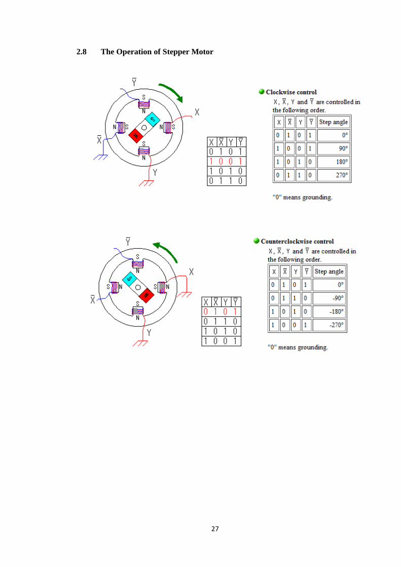
2.8 The Operation of Stepper Motor
Page 28
28
2.9 Wire Connection Diagrams
Figure 15: Wire connection diagrams
Page 29
29
3.0 METHODOLOGY
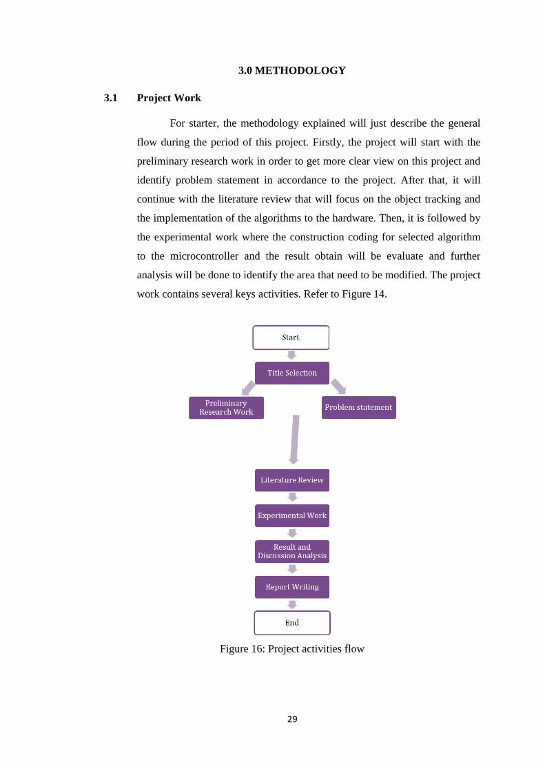
3.1 Project Work
For starter, the methodology explained will just describe the general
flow during the period of this project. Firstly, the project will start with the
preliminary research work in order to get more clear view on this project and
identify problem statement in accordance to the project. After that, it will
continue with the literature review that will focus on the object tracking and
the implementation of the algorithms to the hardware. Then, it is followed by
the experimental work where the construction coding for selected algorithm
to the microcontroller and the result obtain will be evaluate and further
analysis will be done to identify the area that need to be modified. The project
work contains several keys activities. Refer to Figure 14.
Figure 16: Project activities flow
Page 30
30
3.2 Object Tracking Closed-Loop Control System
Below is the closed-loop control system (refer Figure 15) where
inside the dot line is microcontroller Arduino Uno. SP can be defined as the
set point, for positioning sensors used are infrared and the actuator is stepper
motor
Figure 17: General closed loop system block diagram
Figure 18: Object tracking closed loop system block diagram
Page 31
31
Pseudo code for stepper motor control
1) Initialize ports
Pin 1-4 outputs to stepper motor
Pin 1 to wire A, Pin 2 to wire B, Pin 3 to A‟, Pin 4 to B'
Pin 13 output to LED
Pin 5 input from infrared sensor (receiver), which receives signal from infrared
transmitter
2) Pin 5 – gets signal from infrared
3) Pin 1-4 – stepper motor turns clockwise approximately in 180 degrees for 1100, 0110,
0011, 1001
Page 32
32
3.3 Gantt Chart
Figure 20: Gantt chart for FYP1
3.4 Key Milestone
Figure 21: Key milestone for FYP1 and FYP2
Page 33
33
3.5 Tools and Hardware Required
Software Hardware
Arduino Integrated Development
Environment (IDE)
Stepper Motor
Fritzing Software Stepper Motor Circuitry
ISIS Professional 7.10 Voltage Regulator Circuitry
IronCAD 10.0 Battery / Power Supplies
Arduino Uno Microcontroller
USB Cable
Infrared Sensors
Sensors Circuitry
555 Timer (NE555N)
Jumpers
Table 5: Tools and hardware required
Page 34
34
Software Characteristics
Arduino Integrated Development
Environment (IDE)
The steps involved are:
Create compile upload run finish
It allows the process of programming to be much
faster [24]
Designed with C/C+ library
There are two functions :
setup()
loop()
Fritzing Software
Able to generate a Printed Circuit Board (PCB)
design in order to record Arduino-based prototype.
It is an Electronic Design Automation (EDA) and
breadboard based prototype.
ISIS Professional 7.10
Utilise the tools also for Printed Circuit Board (PCB)
layout to generate a professional schematic
Retain a basic simulation also can be implement for
microcontroller
Page 35
35
Hardware
Stepper Motor Power Supply +9V and +6V
Arduino Uno Rev3 USB cable
NE55N Jumper (Male to male)
Page 36
36
4.0 RESULTS AND DISCUSSION
4.1 Infrared Receiver
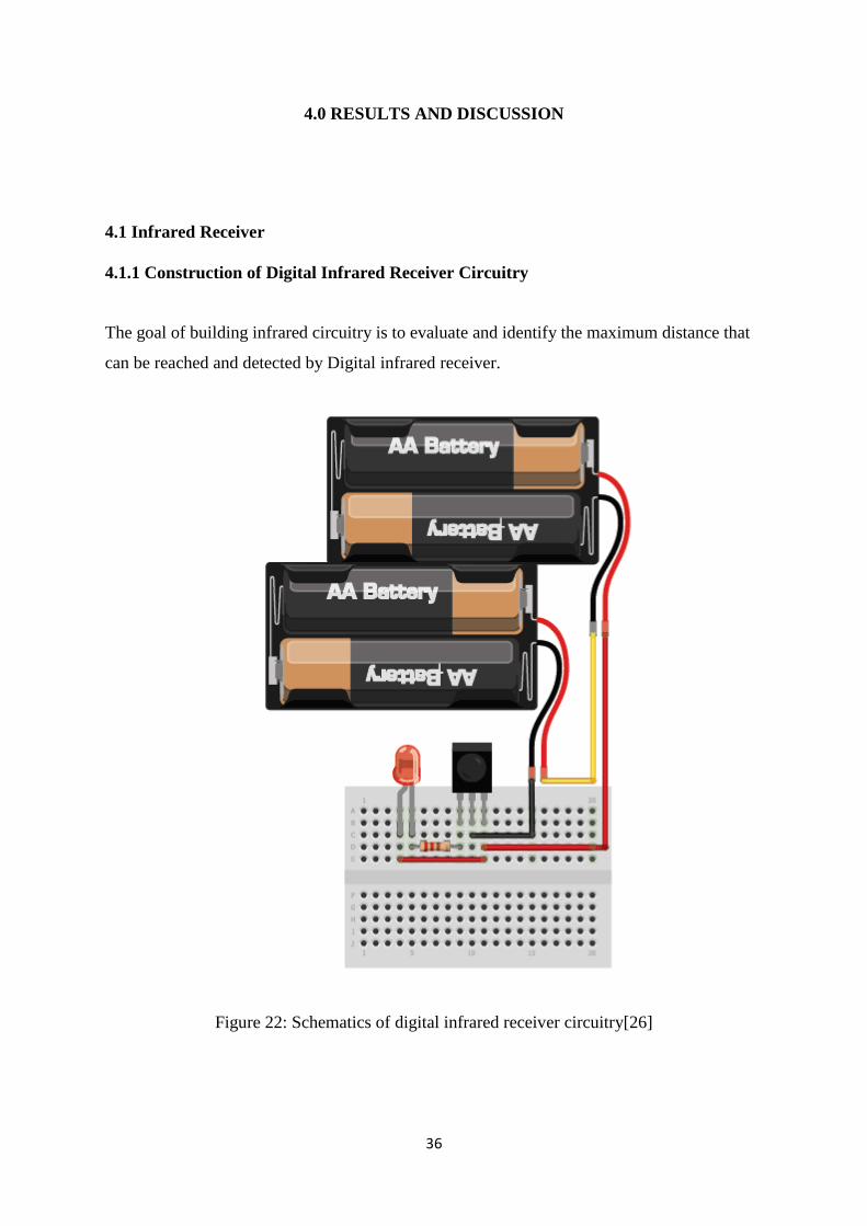
4.1.1 Construction of Digital Infrared Receiver Circuitry
The goal of building infrared circuitry is to evaluate and identify the maximum distance that
can be reached and detected by Digital infrared receiver.
Figure 22: Schematics of digital infrared receiver circuitry[26]
Page 37
37
Figure 23: Digital infrared receiver circuitry
Angle degree (θ) 0 45 90 135 180 225 270 315 360
Distance max (cm) 40 22 21 17 31 320 37 36 35.5
Table 6: Result of maximum angle and distance
Figure 24: Maximum distance (cm) vs Angle (degree)
0
50
100
150
200
250
300
350
0 45 90 135 180 225 270 315 360
Dis
tan
ce m
ax (
cm)
Angle degree
THE MAXIMUM DISTANCE BETWEEN IR TRANSMITTER AND RECEIVER
Page 38
38
Figure 25: Layout of experimental IR receiver and IR transmitter
Figure 26: Distance between IR receiver and IR transmitter in different angles (IronCAD)
Page 39
39
4.2 Infrared Transmitter
4.2.1 Construction of Infrared Transmitter Circuitry
Calculation of 555 timer
In order to select the value of 1R1, R2 and C, it is required to calculate as the formula stated
before.
Select R1 to be 10kΩ and R2 is 14kΩ
))
After that, sketch and design the circuit using ISIS Professional 7.0 software and Fritzing
software. The schematic is shown below.
Figure 27: Schematics of 555 timer circuitry using ISIS Professional 7.0
Page 40
40
Figure 28: Graph obtained from simulation
Figure 29: Schematics of 555 timer circuitry using Fritzing
Page 41
41
Figure 30: 555 timer circuitry connected to digital infrared transmitter
Figure 31: Graph obtained from digital oscilloscope
Page 42
42
Maximum distance 3.2m
Frequency (mean) 36.2530kHz
Time 18 s
Output Voltage 1.3V
Table 7: IR transmitter efficiency to transmit
Reading Desired Frequency Actual Frequency Percentage Error (%)
1 4.63
2 4.59
3 4.58
4 4.35
5 4.48
Table 8: Percentage errors from several trials
The percentage of error can be calculated using this formula:
100||
% xeActualvalu
eActualvaluueDesiredvalError
There are some errors due to human errors, systemic errors and random errors such as the
calibration of digital oscilloscope has systemic error ±5%, the experimental condition and
surroundings.
Page 43
43
Figure 32: Graph of actual vs desired frequency value
1 2 3 4 5
Actual 36.2168 36.2266 36.2362 36.3165 36.2686
Desired 37.8947 37.8947 37.8947 37.8947 37.8947
35
35.5
36
36.5
37
37.5
38
38.5
Fre
qu
en
cy o
f IR
tra
nsm
itte
r
Page 44
44
4.3 Stepper Motor
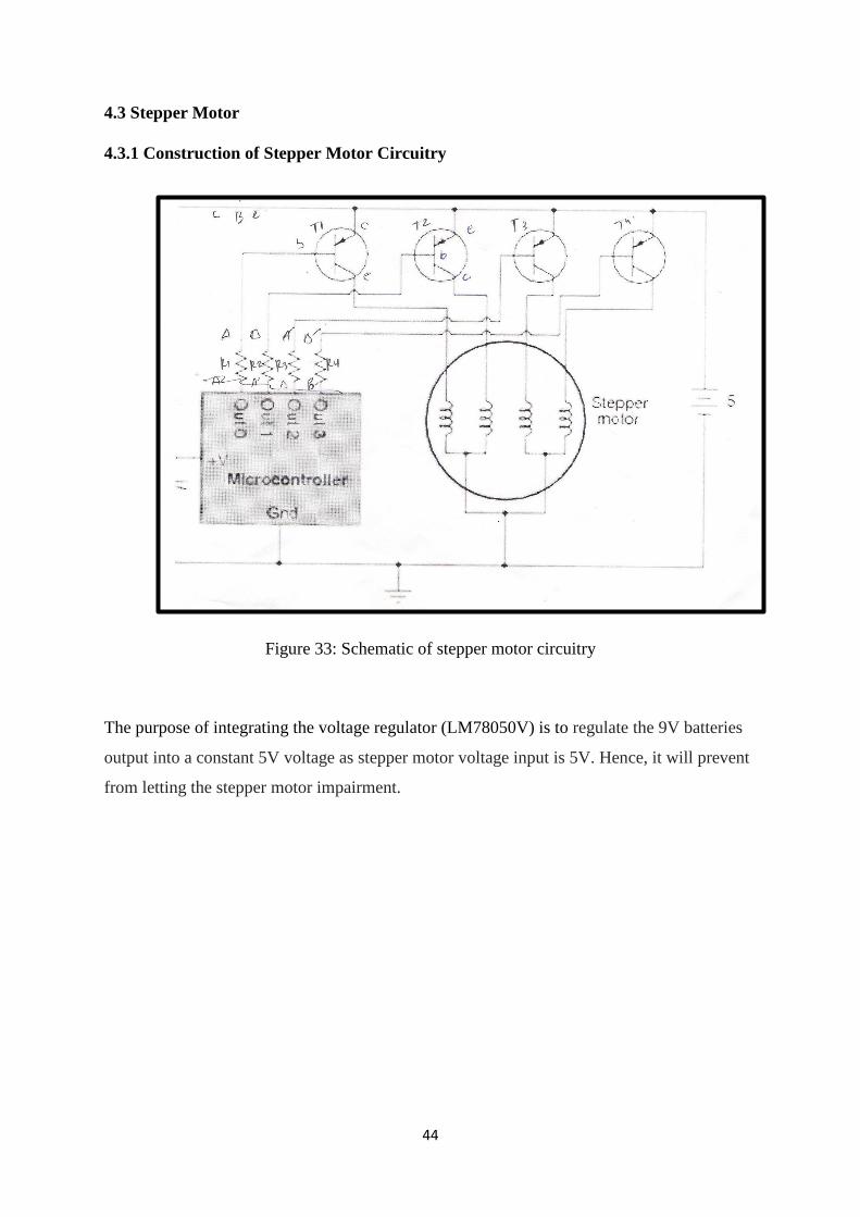
4.3.1 Construction of Stepper Motor Circuitry
Figure 33: Schematic of stepper motor circuitry
The purpose of integrating the voltage regulator (LM78050V) is to regulate the 9V batteries
output into a constant 5V voltage as stepper motor voltage input is 5V. Hence, it will prevent
from letting the stepper motor impairment.
Page 45
45
The components employed in the stepper motor circuitry are
+9V battery and battery snap
Voltage Regulator (LM78050V)
Four Power Transistors
Four Resistors (1kΩ)
Stepper Motor
Capacitors (100nF)
Page 46
46
Figure 34: Voltage regulator circuitry
Figure 35: Schematic diagram of stepper motor and voltage regulator (veroboard)
Page 47
47
Figure 36: Circuit of stepper motor and voltage regulator
4.3 Integration of Stepper motor circuitry and Infrared receiver circuitry
The approach used is the infrared detection and tracking algorithm in Arduino Uno code, pin 5 as the
input of infrared receiver. Once the digital infrared receiver caught signal, the output will be the
rotation of the stepper motor. In this case, the stepper motor will turn in clockwise direction. From the
project, if I want to relate this to real situation, transmitter can be described as an object that is
detected by the sensor which is in this case is IR receiver. Consequently, to show that the
microcontroller will further analysed data obtained from the IR receiver (input data) the
output is the moving stepper motor in 180 degree approximately.
Page 48
48
Figure 37: The integration of stepper motor and IR receiver circuitry to Arduino
Problem encountered
Sometimes, when infrared transmitter transmits to IR digital receiver, it delays a few minutes,
such as the stepper motor will rotate to clockwise direction not precisely in the same time
when the infrared receiver acquire the signals.
Page 49
49
5.0 CONCLUSION
5.1 Conclusion
At the end of this project, it is shown that the object tracking is worked accordingly.
The method used is infrared search and track (IRST) and closed loop system PID
controller involving the stepper motor, Arduino Uno and infrared transmitter and
receivers. The improvement can be further do by increasing the tracking accuracy
with better algorithm such as PI controller and using the most sensitive infrared
transmitter and receiver. For future extension work, complex coding can define the
stability and precision of the stepper motor rotation and reaction. Adding more
infrared receivers can control variety of angles and directions.
Page 50
50
REFERENCES [1] azega. Controlling a stepper motor with an arduino. Retrieved July 19, 2012, from azega
[2] azega. Stepper driver. Retrieved July 19, 2012, from azega
[3] handyboard. Hardware faqs for dc-vs-servo. Retrieved July 26, 2012, from handyboard
[4] probotix. Unipolar. Retrieved July 26, 2012, from probotix
[5] machinetoolhelp. Stepper dc-vs-servo. Retrieved July 30, 2012, from machinetoolhelp
[6] Arun Israel, Reda Dehy. (2004). Cornell University ECE 476 Final Project.
[7] Yiwei Wang, John F. Doherty, Robert E. Van Dyck. Pennsylvania State University and National
Institute of Standards and Technology.
[8] Konstantinos E. Papoutsakis, Antonis A. Argyros. Institute of Computer Science, FORTH and
University of Crete.
[9] Sebastian de Vlaam. (2004). Smart Sensor Solution. Network Embedded Systems.
[10] Boryslav Larin. (2011). Department of Applied Mathematics and Information Software
Engineering.
11-14] cornell. Retrieved September 10, 2012, from
http://people.ece.cornell.edu/land/courses/ece4760/FinalProjects/s2012/xz227_gm348/xz227_gm3
48/index.html
[15] arduino for beginners. Retrieved September 10, 2012, from http://arduino-for-
beginners.blogspot.com/2010/11/so-many-types-of-arduino-which-one.html
[16] instructables. Retrieved September 12, 2012, from http://www.instructables.com/id/Intro-to-
Arduino/
[17] instructables. Retrieved September 10, 2012, from http://www.instructables.com/id/Intro-to-
Arduino/
[18] KCytron Technologies. (May 2010). IR Sensors Version 1.1.
[19] Fernando Montes-Gonzalez, Daniel Flandes-Eusebio, Luis Pellegrin-Zazueta. (2012). Action
Selection and Obstacle Avoidance Using Ultrasonic and Infrared Sensors. Department of Artificial
Intelligence, University of Veracruzana.
[20] Keith W. Gray. (2000). Obstacle Detection and Avoidance for an Autonamous Farm Tractor.
Master of Science.
[21] scribd. Retrieved September 13, 2012, from http://www.scribd.com/doc/45627872?Mini
[22] Embedded Solutions. Retrieved September 10, 2012, from http://www.embedded-
solutions.dk/uhh/articles/555-Timer.html
Page 51
51
[24] wisegeek. Retrieved September 10, 2012, from http://www.wisegeek.com/what-is-an-arduino-
ide.htm
[25] Sushil Kumar, Prof. U.B. Desai (2004). Detection and Tracking Algorithms for Infrared search and
track. EE department Bombay.
[26] Ladyada, testing infrared sensor, adafruit US
.
Page 52
52
APPENDIX A
DATASHEET OF STEPPER MOTOR
Page 54
54
APPENDIX B
DATASHEET OF POWER TRANSISTOR (TIP31A)
Page 55
55
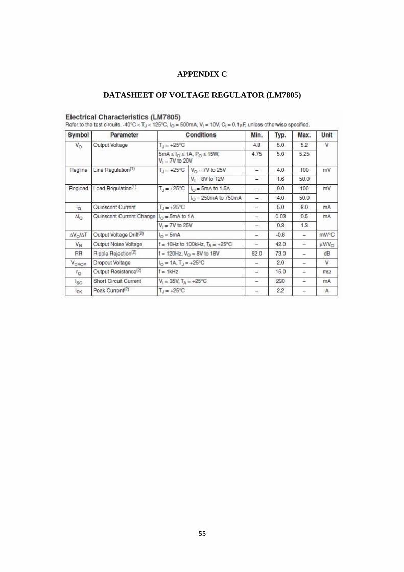
APPENDIX C
DATASHEET OF VOLTAGE REGULATOR (LM7805)
Page 56
56
APPENDIX D
DATASHEET OF DIGITAL INFRARED RECEIVER
Page 57
57
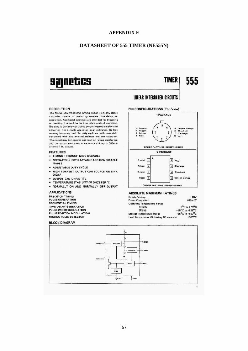
APPENDIX E
DATASHEET OF 555 TIMER (NE555N)
Page 58
58
APPENDIX F
LAYOUT OF CONFIGURATIONS OF ARDUINO UNO
Page 59
59
APPENDIX G
DATASHEET OF ATMEGA328P-PU
Page 60
60
APPENDIX H
ARDUINO STEPPER MOTOR AND INFRARED CONTROL CODE