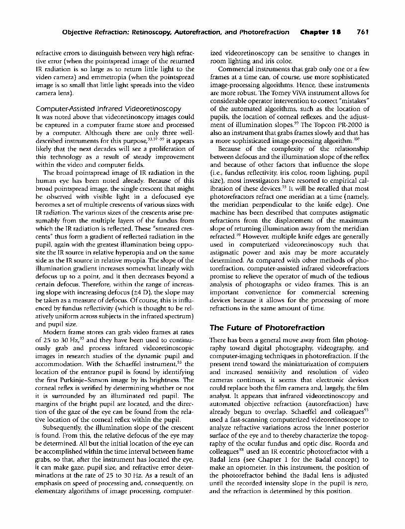
18 Objective Refraction: Retinoscopy, Autorefraction, and Photorefraction Charles E. Campbell, William J. Benjamin, Howard C. Howland T he term "objective refraction" is used when the refractive error of an eye is determined without input by the patient. The patient may be required to cooperate during the placement of the head and to fixate on a target for a short time, but subjective infor- mation is not obtained from the patient about the quality of vision during the procedure. Therefore, a patient's judgment is not required to derive an objective refraction. The refractive error is determined according to a set of criteria identified in advance by a human operator or by a programmed instrument. Retinoscopy is a form of objective refraction in which the judgment of a human operator is required to determine the refrac- tive error. Certain optometers, as noted in Chapter 1, can also provide objective assessments of refractive error. These optometers require that the endpoints be achieved by action of the human operator. When the judgment of a human operator is replaced by the logic of an instrument, a computer, or both and when the endpoint is reached by action of the instru- ment or computer, the objective refraction has been automated. Thus, an automated objective refraction does not require evaluations by a patient or an opera- tor in the derivation of the refractive error. It is accepted that a patient must be cooperative and that an operator may be necessary to ensure that conditions are met for proper functioning of the instrument and computer. Some automated objective refractors are more fully automated than others; thus, some of the requirements for patients and operators have been alleviated. For instance, certain automated objective refractors employ an autocentration mechanism to keep the instrument aligned and focused on the center of the entrance pupil after the operator has initially aligned and focused the instrument. Some automated objective refractors are equipped with an autofogging function to help the patient's accommodative system relax before measure- ment. Because the automation trend will continue, it 682 appears that the current requirements for an operator and for patient cooperation may slowly erode in the future. Refractive error can be estimated objectively by a process called photorefraction. A photograph or video- graph of the pupils is currently interpreted by a trained operator or clinician, but attempts are being made to automate the interpretations of photographic and videographic refractors. Photorefraction is especially useful when patient cooperation cannot be well maintained. THE EYE: A CLOSED OPTICAL SYSTEM Focusable light can only enter or exit the normal eye through the pupil. To measure the optical characteris- tics of a closed optical system, light must traverse the optical path twice, and there must be some structure at the closed end of the optical path that can reverse the direction oflight travel. The retina-or, more accurately, the ocular fundus-acts as the primary reflector that reverses the direction of light in the eye such that light emitted from the eye can be analyzed. The fundus reverses the direction of light travel through a combi- nation of reflections occurring at refractive index inho- mogeneities at surfaces or within the tissue. Specular reflections from the ocular fundus occur according to intensities derived from Fresnel's formula for specular reflection at the layered concave optical interfaces between the vitreous, the retina, the pigment epithe- lium, and the choroid (Figure 18-1). Specular reflections also occur at the interfaces between the transparent media of the eye, and these result in what are called the Purkinje-Sanson images; these reflections must not be allowed to significantly interfere with analysis of the fundus reflex.
Transcript
18
Objective Refraction: Retinoscopy,Autorefraction, and Photorefraction
Charles E. Campbell, William J. Benjamin,Howard C. Howland
The term "objective refraction" is used when therefractive error of an eye is determined without
input by the patient. The patient may be required tocooperate during the placement of the head and tofixate on a target for a short time, but subjective information is not obtained from the patient about thequality of vision during the procedure. Therefore, apatient's judgment is not required to derive an objectiverefraction. The refractive error is determined accordingto a set of criteria identified in advance by a humanoperator or by a programmed instrument. Retinoscopy isa form of objective refraction in which the judgment ofa human operator is required to determine the refractive error. Certain optometers, as noted in Chapter 1,can also provide objective assessments of refractiveerror. These optometers require that the endpoints beachieved by action of the human operator.
When the judgment of a human operator is replacedby the logic of an instrument, a computer, or both andwhen the endpoint is reached by action of the instrument or computer, the objective refraction has beenautomated. Thus, an automated objective refractiondoes not require evaluations by a patient or an operator in the derivation of the refractive error. It is acceptedthat a patient must be cooperative and that an operatormay be necessary to ensure that conditions are met forproper functioning of the instrument and computer.Some automated objective refractors are more fullyautomated than others; thus, some of the requirementsfor patients and operators have been alleviated. Forinstance, certain automated objective refractors employan autocentration mechanism to keep the instrumentaligned and focused on the center of the entrance pupilafter the operator has initially aligned and focused theinstrument. Some automated objective refractors areequipped with an autofogging function to help thepatient's accommodative system relax before measurement. Because the automation trend will continue, it
682
appears that the current requirements for an operatorand for patient cooperation may slowly erode in thefuture.
Refractive error can be estimated objectively by aprocess called photorefraction. A photograph or videograph of the pupils is currently interpreted by a trainedoperator or clinician, but attempts are being made toautomate the interpretations of photographic andvideographic refractors. Photorefraction is especiallyuseful when patient cooperation cannot be wellmaintained.
THE EYE: A CLOSEDOPTICAL SYSTEM
Focusable light can only enter or exit the normal eyethrough the pupil. To measure the optical characteristics of a closed optical system, light must traverse theoptical path twice, and there must be some structure atthe closed end of the optical path that can reverse thedirection oflight travel. The retina-or, more accurately,the ocular fundus-acts as the primary reflector thatreverses the direction of light in the eye such that lightemitted from the eye can be analyzed. The fundusreverses the direction of light travel through a combination of reflections occurring at refractive index inhomogeneities at surfaces or within the tissue. Specularreflections from the ocular fundus occur according tointensities derived from Fresnel's formula for specularreflection at the layered concave optical interfacesbetween the vitreous, the retina, the pigment epithelium, and the choroid (Figure 18-1). Specular reflectionsalso occur at the interfaces between the transparentmedia of the eye, and these result in what are called thePurkinje-Sanson images; these reflections must not beallowed to significantly interfere with analysis of thefundus reflex.
Objective Refraction: Retinoscopy, Autorefraction, and Photorefraction ' Chapter 18 683
CHOROID
PIGMENTEPITHELIUM
LAYER OF RODSAND CONES
OUTER NUCLEARLAYER
OUTER PLEXIFORM {LAYER
RETINA/PIGMENT-+---EPITHELIUM INTERFACE
..-OUTER LIMITINGMEMBRANE
INNER NUCLEARLAYER
INNER PLEXIFORMLAYER
GANGLION CELLLAYER
OPTIC NERVEFIBER LAYER
tVITREOUS
t t
VITREORETINALINTERFACE
.- ORINNER LIMITING
MEMBRANE
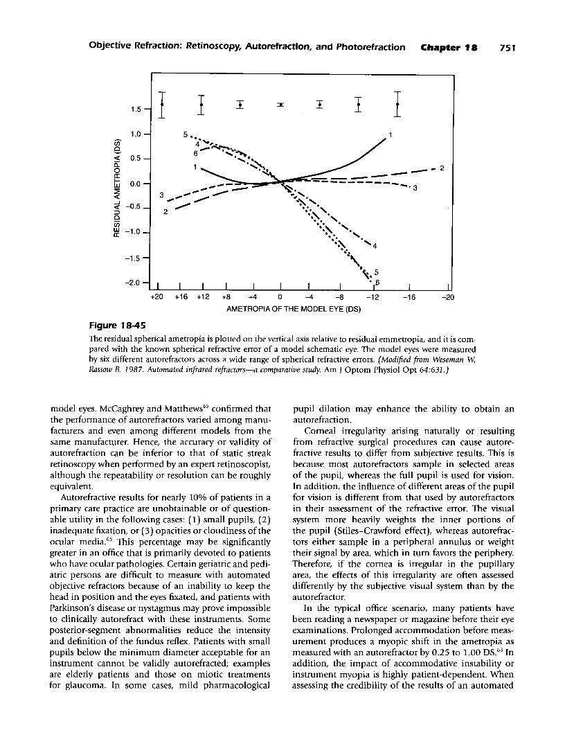
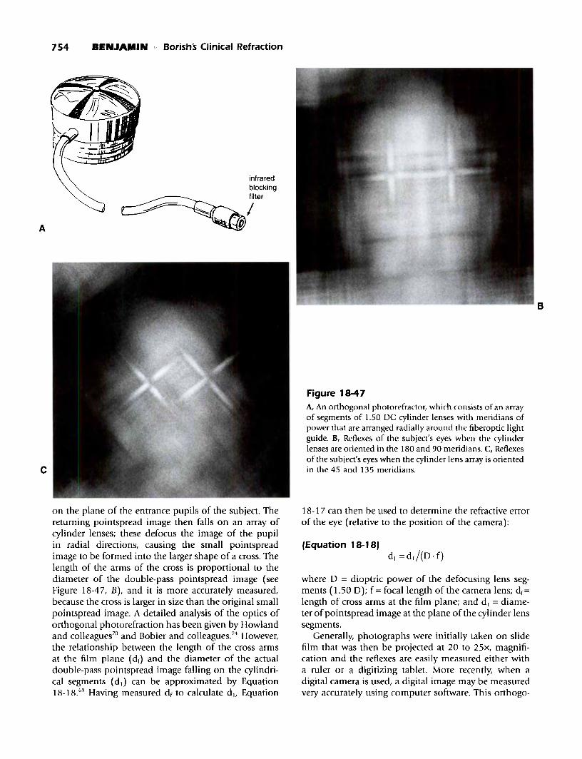
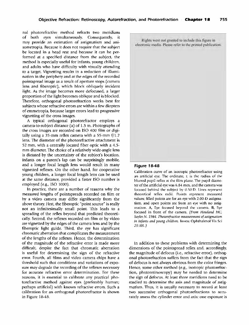
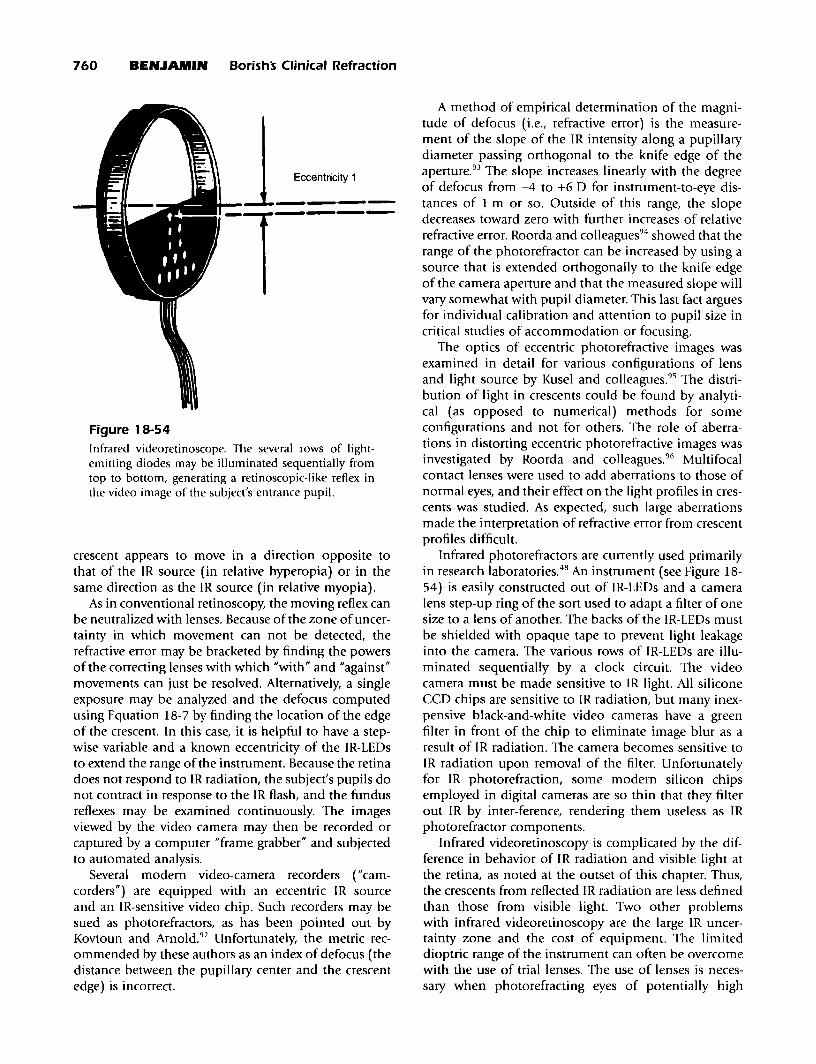
Figure 18-1Cross-sectional diagram of the retina showing the potential positions of the effective ocular reflecting surfaceat the retina/pigment epithelium interface, the outer limiting membrane, and the vitreoretinal interface. Theouter limiting membrane of the retina is most likely the layer onto which best image focus is attained duringthe subjective refraction. (Adapted from Polyak SL. 1941. The Retina. University of Chicago. )
(Equation 18-1)
[n' _n]2r- --
n' +n
where r = relative reflectance of the interface from 0 to1; n' = refractive index of the medium into which theincident light is going; and n = refractive index of themedium from which the incident light is leaving.
The major specular reflection that interferes withobjective refraction is the corneal reflex, because it iscomposed of 2.1% of the light incident on the cornea,and it is located approximately at the entrance pupil ofthe eye. The intensities of the other Purkinje-Sanson
images are between 0.022% and 0.085%, and they generally align behind the corneal reflex when observedfrom a position along the optic axis of the eye (i.e., asis seen with objective refraction). Specular reflectionfrom the vitreoretinal interface is of low intensity(0.08% of incident light), but it is located near thefundus, and it can confuse the analysis of the fundusreflex. It may seem counterintuitive that the vitreoretinal reflex is important; however, as a specular reflectorclose to the focus of the eye, the vitreoretinal surface isefficient for reflecting near-normal light back out of theeye through the pupil. Light is essentially retroreflectedalong the path from which it came, and little returned
684 BENJAMIN Barish's Clinical Refraction
light is lost by masking at the pupil. Millodot andO'Learyl concluded that the vitreoretinal reflex contributes significantly to the fundus reflexes of youngpatients when visible light is used during retinoscopyand photorefraction.
The radius of curvature of the foveal pit is less thana millimeter.2 Reflections from the region of the fovealpit are complex, because the vitreoretinal surface ishighly curved, and the curvature rapidly varies fromconvex to concave. The surface is toroidal in transition.In retinal photographs, the foveal reflex is sometimesseen as a ring of light surrounding the fovea or a spotof light at the fovea. For the greater portion of thefundus, however, the vitreoretinal interface can be considered to be a concave semitransparent mirror with aradius of curvature of about 12 mm and a center of curvature on the optical axis of the eye. The vitreoretinalmirror's image of the primary source becomes a secondary fundus source for return out of the eye to a planein visual space that is optically conjugate with the secondary fundus source. Progressively less light is returnedto a position of observation near the optic axis of theeye as illumination is moved away from the fovea. Thus,the contribution of the vitreoretinal reflex to lightreturning to a position of observation is greatest whenthe macular region is illuminated. This is the regionassessed during an objective refraction.
The axial location of the secondary vitreoretinalsource depends on the vergence of light that strikes thevitreoretinal surface. If the light is diverging from a pointbetween the vitreoretinal mirror and its focal plane6 mm in front of the mirror (Le., as would occur in amyopic eye viewing a distant primary source), the imageproduced by the vitreoretinal mirror lies posterior to themirror. If this image happens to coincide with the effective ocular reflecting surface, both surfaces contribute tothe same objective refractive error determination. To theextent that the vitreoretinal image is located away fromthe effective ocular reflecting surface, the correspondingrefractive errors diverge, and the net effect is an averagederror. In practice, the vergence of light incident at the vitreoretinal interface is a function of the refractive statusof the eye, of the corrective lenses employed, and of thevergence of incident light. Therefore, the impact of thevitreoretinal reflex on the result ofan objective refractionshould vary highly among patients.
It is a well-known concept in visual optics that300 Ilm of axial distance at the retina (0.3 mm) isapproximately equivalent to 1.00 0 of refractive error.When the endpoint of refraction is a neutralization ofthe refractive error (as is the case for retinoscopy and forsome automated objective refractors), it is possible tomake the vitreoretinal reflex nearly coincident with theeffective ocular reflecting surface at neutralization. Thiscan be done by focusing the incoming light so that it isconvergent by +0.67 OS to +0.82 OS; this moves the vitreoretinal reflex 200 to 245 Ilm posteriorly. This places
the vitreoretinal reflex at the position of the outer limiting membrane or the retina/pigment epithelium interface, respectively, both of which are candidates to be theeffective ocular reflecting surface (see below). The effectof the vitreoretinal reflex on the objective refraction isthen minimized when neutralization is achieved.
Effective Surface forSubjective Refraction
The retinal surface effectively responsible for detectionof the image during the subjective refraction is the outerlimiting membrane/ which separates photoreceptorinner segments and nuclei from their photosensitiveouter segments (see Figure 18-1). The outer lim itingmembrane lies approximately 45 Ilm in front of thepigment epithelium but approximately 200 Ilm behindthe vitreoretinal interface. Although there are subtleindex changes in the retina, the retina is essentiallytransparent until light arrives at the anterior ends of thereceptor outer segments at the outer limiting membrane. The retinal receptors act as optical waveguides forvisible light because of their tubular structure and theindex gradient between the internal medium of the celland the cell membrane.4 The receptors are packedtightly together within the retinal layer of rods andcones, and the resulting total structure acts like a coherent fiberoptic plate extending from the outer limitingmembrane to the pigment epithelium. A fiberoptic platehas the characteristic that the optical effects of a diffusesource placed on one side are transferred to the otherside such that the two sides are effectively in directcontact. Therefore, incident light rays that strike theouter limiting membrane are efficiently transmitted tothe photosensitive pigments in the outer segments by awaveguide mechanism.
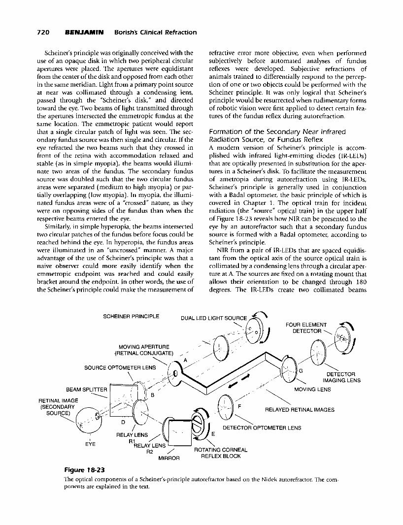
Formation of the Secondary FundusSource, or "Fundus Reflex"
Light reflected from the fundus has two components:(1) a diffuse component, which is also called backscatter,the result of light scattered because of reflection frommicroscopic and macroscopic particles or structureswithin the volume of the retina, the pigment epithelium, the choroid, or even the sclera (see Figure 18-1),and (2) a directed component, the result of light thathas been reflected from the neighborhood of theretina/pigmented epithelium interface and is waveguided by the retinal cones.4a
-4d
Diffusely reflected light is backscattered through alarge solid angle, and a great proportion of it is blockedfrom escaping through the pupil. Consider a normal eyewith a 4-mm pupil located 20 mm from the retina. Thesolid angle through which light can exit the eye is only0.0314 steradians. Ifone assumes that the fundus reflex isLambertian (Le., perfectly diffusing), less than 3.14% of
Objective Refraction: Retinoscopy, Autorefraction, and Photorefraction Chapter 18 685
the fundus reflex exits the eye. In the visible spectrum, thereflectivity of the pigment epithelium is between 0.5%and 7.0%.5 Therefore, the proportion of incident lightthat is returned from the pigment epithelium throughthe pupil is between 0.016% and 0.22%, which is ofsimilar magnitude to that of the vitreoretinal reflex(0.08%). One can now understand why the corneal reflex(2.1% of incident light) and light backscattered frommedia opacities or clouding can interfere with analysis ofthe fundus reflex during an objective refraction.
The most significant sources of diffuse visible lightare the pigment epithelium and the choroid. These arecomplex structures that are heterogeneous and thatcontain several important absorbers of light: melanin,hemoglobin, and xanthophil. The highest concentration of melanin is in the pigment epithelium, and thehighest concentration of hemoglobin occurs in thedense capillary net of the choriocapillaris, which liesdirectly behind the pigment epithelium and is of thesame thickness (10 11m). Light that returns from thesestructures is the result of competition between absorption and backscatter. Hence, the fundus reflex is of a redor orange color during retinoscopy and photorefraction.
The directed component of the fundus reflex originates from a very thin layer of tissue in the neighborhood of the retina/pigment epithelium interface and ismost likely due to Fresnel reflection from melanin granules in the pigment epithelium. These granules have ahigh index of refraction (1.7) compared with surrounding tissue (1.34) that makes them reflect about1.2% of the incident light (see Equation 18-1). Thislight reenters the cones, is wave-guided through them,and issues as narrow directed beams with approximatelyGaussian intensity profiles. 4a By the time the beamsreach the pupil of the eye, they have spread to approximately fill the pupil yet still retain Gaussian intensityprofiles. The multiple beams overlap in the pupil andform a single intensity pattern that retains the Gaussianprofile. So, while the intensity of the directed component is reduced, it is not reduced nearly as much as thediffuse component of the fundus reflex, which is spreadthrough a much wider solid angle when it reaches thepupil. It is of interest that about half of the lightreflected from the retina/pigment epithelium interfaceretains polarization of incident light. 6 For this amountof polarization to occur, there must be a low amountof multiple scattering in this component of the fundusreflex, because multiple scattering would causedepolarization.
Delori and Ptlibsen5 concluded that the magnitude ofthe reflectance and the apparent depth of the backscattervolume depend highly on wavelength. Because theocular absorbers of radiation are less efficient for absorbing infrared radiation, backscattering of infrared radiation occurs throughout the pigment epithelium andchoroid, but is greatest at the interface between thechoroid and the sclera. The reflectivity of the sclera is
40% to 50%, which retroilluminates the choroid andpigment epithelium with infrared radiation. Thus, thefundus reflex stems from an optically thick depth oftissue behind the retina when composed of infraredradiation during automated objective refraction.
The interface between a diffusely reflecting structure(the pigment epithelium) and an adjacent transparentmaterial (the retina) is the effective surface from whichfocusable visible light or infrared radiation originates.No focusable rays can form until radiation emergesfrom the surface of the backscattering structure into atransparent medium. Because of the waveguide natureof the layer of rods and cones for visible light (notedpreviously), the optical qualities of the epithelial surfaceare transferred to the outer limiting membrane. Hence,the effective ocular reflecting surface for visible light isat the outer limiting membrane during the performanceof retinoscopy or photorefraction. The waveguide natureof the retinal layer of rods and cones is weaker forinfrared radiation?; thus it might be thought that theeffective ocular reflecting surface is the retina/pigmentepithelium interface when infrared radiation is usedto illuminate the fundus. However, Williams and colleagues8 believe the waveguide mechanism to be sufficiently effective for infrared radiation (during its doublepass through the layer of rods and cones) that the outerlimiting membrane is the effective ocular reflectingsurface during automated objective refraction. Indeed,Lopez-Gil and colleagues43 have shown that, even forinfrared radiation, the outer limiting membrane is closeto the effective ocular reflecting surface.
It can now be noted that, in the case ofobjective refraction with visible light, the effective surfaces for reflectionand subjective refraction are probably coincident. Thedepth of tissue from which visible light is backscatteredis smaiL and fundus reflexes of visible light are quasispecular. For infrared radiation, the effective ocularreflecting surface may lie behind the effective surface forsubjective refraction by approximately 45 11m (0.15 D),but these effective surfaces could also be coincident ifthewaveguide mechanism is sufficiently effective forinfrared wavelengths. The depth of tissue from whichinfrared radiation is backscattered is large, and thefundus reflexes of infrared radiation are more diffuse. 8
Therefore, the definition of a fundus reflex with visiblelight is much better than an identical reflex producedwith infrared radiation. The impacts of these aspects ofvisible and infrared radiations on objective refraction arediscussed in later sections, because they are specific to themode of objective refraction employed.
STATIC STREAK RETINOSCOPY
The technique of retinoscopy is used to objectivelydetermine the refractive status of the eye relative to thepoint of fixation. Retinoscopy is usually the first tech-
686 BENJAMIN" Borishs Clinical Refraction
nique performed during the ocular examination thatdetermines the patient's refractive status, and it isimmediately followed by the subjective refraction (seeChapter 20). The retinoscopic findings, therefore,usually serve as the starting point for the subjectiverefraction, and they are independent confirmation ofthe subjective results. Retinoscopy can be performed oninfants, the mentally infirm, low-vision patients, anduncooperative or malingering patients. Thus, theretinoscopic findings may be heavily relied on for theprescription of optical corrections when patients areunable or unwilling to give reliable subjective responses.
In 1859, Sir William Bowman noticed a peculiarreflex in the pupil of astigmatic eyes that occurredduring ophthalmoscopy, and he used the reflex in thediagnosis of astigmatism. 10 Cuignet~ made known theclinical use of retinoscopy for the qualitative determination of refractive status, and explanations of theoptical concepts underlying retinoscopy were firstattempted by Landolt in 1878. Parent updated theoptical theory in 1880, and he began to quantitativelyassess the refractive error through the use of lensesinserted in front of the eye. IO Retinoscopy is actually amodification of the Foucault knife-edge method fordetermining the refractive power of a lens applied tothe eye. Commonly used synonyms of retinoscopy are"skiascopy" and "skiametry," and other synonymsoccasionally seen in literature were "umbrascopy, II
"pupilloscopy, II and "retinoskiascopy." The misnomer"retinoscopy" ("vision of the retina") was initiated byParent in 1881, and it has been generally accepted inEnglish-speaking countries, although the technique maynot really measure refractive status with respect to theretina. The term "skiascopy" ("vision of shadows") wasalso suggested and favored by Parent, and it becamethe accepted name of the technique in non-Englishspeaking countries. Jackson and Copeland gaveretinoscopy great clinical emphasis during the late 19thand early 20th centuries. n.12
In this section, the determination of ametropic correction during fixation at distance is covered withaccommodation relaxed. However, retinoscopy mayalso be used when fixating a near target, as noted at theend of this section. The procedures for "near"-orIIdynamic"-retinoscopy are further covered in Chapter21. The basic concepts of dynamic retinoscopy, which isperformed when accommodation is allowed to normally function when attending to a near target, are thesame as those of "static" retinoscopy, when attempts aremade to relax accommodation to a resting level whenattending to a distant target. Thus, the principlesinvolved in static retinoscopy are important when otherassessments of the visual system are discussed.
A retinoscope is a small, handheld device that emitsvisible white light toward the pupil of the eye being analyzed and allows the operator to view the red reflex of
light reflected back through the pupil from the ocularfundus. It is actually a modified form of the ophthalmoscope. Typically, the retinoscope has a plane reflecting surface (Figure 18-2), which allows light originatingfrom below to be reflected toward the patient's eye. Thereflecting surface is perforated or half-silvered, whichallows the operator to view the patient's eye through acentral aperture. A divergent beam of light from a filament source is refracted by a plus condensing lensbelow the reflecting surface before it is reflected by theperforated or half-silvered mirror. The reflected beam isusually divergent, and it is directed toward the patient'spupil. Most retinoscopes now have a control for changing the vergence of the emitted light beam; thus, thevergence of the emitted beam can be made significantlydivergent or convergent, and vergence may be variedcontinuously in between. The control is usually a sleeveor collar located in the barrel of the retinoscope, whichcan be made to move up or down. The sleeve or collarallows for the vertical positioning of an adjustable filament source above or below the focal point of a fixedcondensing lens between the source and the reflectingsurface, or it allows for the vertical positioning of anadjustable condensing lens such that its focal point isbelow or above a fixed filament (see Figure 18-2). Themajority of retinoscopists use a divergent setting, andthe examples shown in this chapter assume divergentlight emitted from the retinoscope, except wherespecified.
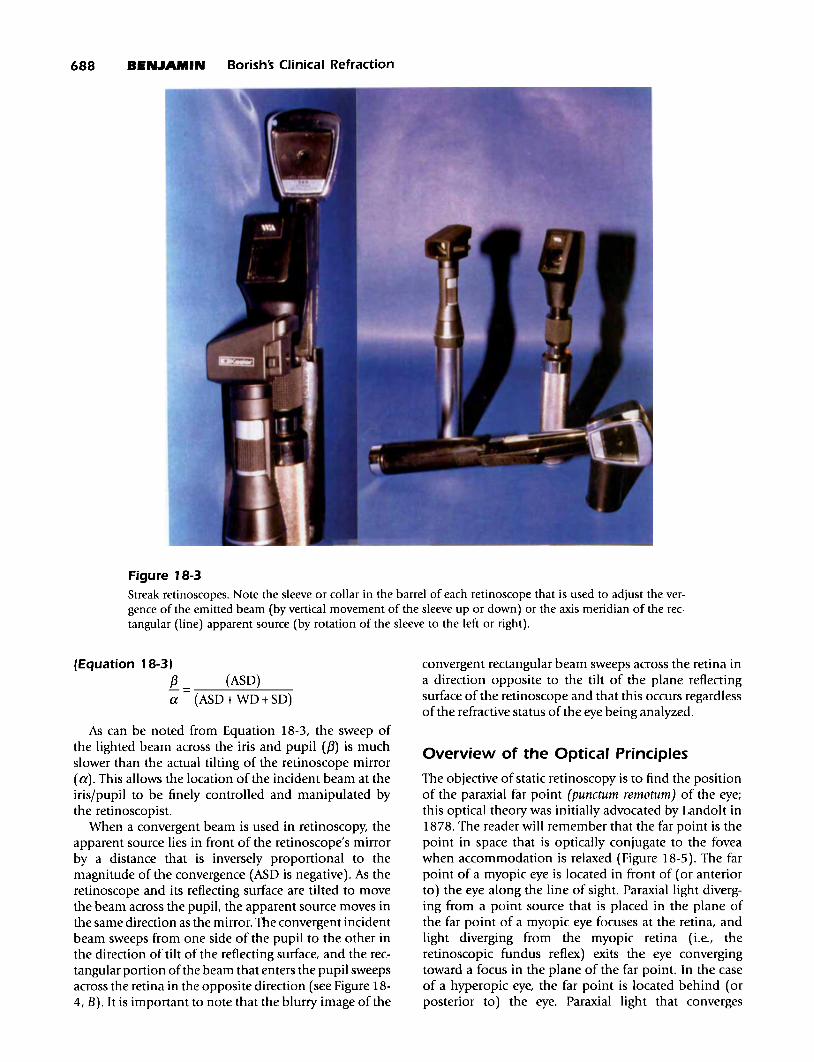
The basic optical design of the retinoscope has notchanged since the latter part of the 19th century. Ofcourse, retinoscopes are now self-luminous (i.e., theyhave their own internal light sources), and they havefiner optical systems resulting from modern electronicsand manufacturing capabilities. A more recent technicaldevelopment is the incorporation of a brighter halogenlight source instead of the earlier incandescent source.The "spot retinoscope II reflects a beam of light from acircular source, whereas the "streak retinoscope II emitsa beam from a line source. The rectangular beam froma streak retinoscope is adjustable for meridional orientation by rotation of the focusing sleeve or collar locatedin the barrel of the retinoscope. Of these two majorforms of retinoscope, the streak retinoscope is moreuseful clinically, because it can be more readily appliedto the determination of astigmatic corrections by assessment of the axis of the cylinder and refractive powersin the two primary ametropic meridians. Therefore, theuse of streak retinoscopy has generally replaced theuse of spot retinoscopy in ophthalmic practice. Streakretinoscopy was a major optical development of theretinoscope. It was attributed to Copeland during theearly 1920s, and he received a patent for it in 1927.Updated versions of the Copeland streak retinoscopeare still manufactured today. Several currently availableretinoscopes are shown in Figure 18-3.
Objective Refraction: Retinoscopy, Autorefraction, and Photorefraction Chapter 18 687
EYE OFPATIENT
oI ADJUSTABLE
VERTICAL POSITIONOF LINE SOURCE (S)ASD(-)
HALF-SILVEREDPLANE MIRROR
SCONVERGENT BEAM(S OUTSIDE FOCUS)
RETINOSCOPE __~~APERTURE •
PERFORATEDPLANE MIRROR
_____ .......-- CONDENSING LENS ---,i.~ "'_-""I
DIVERGENT BEAM(S INSIDE FOCUS)
ASD(+)
S' -ec __
A B
Figure 18-2The optical systems of two retinoscopes. A, The emitted retinoscope beam has been made divergent by placement of the source (S) inside the focal point of the condensing lens. The aperture of the retinoscope, throughwhich the operator views the patient's eye, is created by a perforation in the plane mirror. B, The beam hasbeen made convergent by placement of the source (S) outside the focal point of the condensing lens. Theplane mirror is half-silvered, and the aperture lies behind it. S', The apparent source, formed by the reflection of the retinoscope beam by a plane mirror; ASD, apparent source distance.
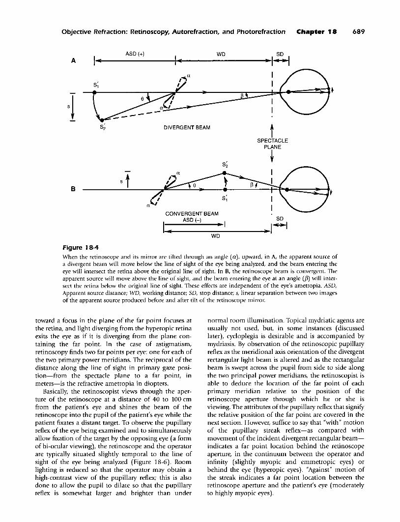
Usually a divergent beam is emitted by theretinoscope, and it is considered the incident beam ofthe optical system underlying retinoscopy (i.e., the beamis incident on the eye). The apparent source of the incident beam (formed by the reflection of the actual sourceby the plane mirror) lies behind the plane reflectingsurface by a distance that is inversely proportional to themagnitude of the divergence (the apparent source distance [ASD] is positive). The incident beam can bemoved by back-and-forth tilting of the retinoscope andits reflecting surface. The long dimension of the streakretinoscope's rectangular beam is set parallel to the axisof the cylinder of the primary power meridian, and thebeam is swept across the pupil in a direction perpendicular to the long dimension, along the primary powermeridian. As the reflecting surface is tilted, the apparentsource moves in the opposite direction, across the lineconnecting the retinoscope aperture and the eye. Thedivergent incident beam sweeps from one side of thepupil to the other in the direction of tilt of the reflectingsurface, and the rectangular portion of the beam thatenters the pupil sweeps across the retina in that directionas well (Figure 18-4, A). For example, if the retinoscopeis tilted toward the left, the beam emerging from theretinoscope (and incident on the eye) moves toward theleft; if tilted down, the emergent beam moves down, andso on. It is important to note that the blurry image of the
divergent rectangular beam sweeps across the retina inthe direction of tilt of the plane reflecting surface of theretinoscope and that this occurs regardless of the refractive status of the eye being analyzed.
The relationship between the angle of tilt of theretinoscope mirror and the angle through which thebeam incident on the iris and pupil has moved can bederived from simple trigonometry applied to Figure 184. If the angular tilt of the retinoscope mirror is denoteda and the angular separation of two incident beamsbefore and after tilt of the retinoscope mirror is denotedf3, then the following is given:
(Equation 18-21s = tan(f3) x (ASD+ WD+SD) = tan(a) x (ASD)
where ASD = apparent source distance from apparentsource to retinoscope aperture (+ for divergent lightemitted from the retinoscope and - for convergentlight); WD = working distance from retinoscope aperture to the spectacle plane (always +); SD = stop distance, spectacle plane to entrance pupil = vertex distance+ 3 mm (always +); and s = linear separation betweentwo images of the apparent source produced before andafter tilt of the retinoscope mirror. Therefore, after simplification and limitation to small angles in radians, thefollowing is given:
688 BENJAMIN Borish's Clinical Refraction
Figure 18-3Streak retinoscopes. Note the sleeve or collar in the barrel of each retinoscope that is used to adjust the vergence of the emitted beam (by vertical movement of the sleeve up or down) or the axis meridian of the rectangular (line) apparent source (by rotation of the sleeve to the left or right).
(Equation 18-31f3a
(ASD)
(ASD+ WD+SD)
convergent rectangular beam sweeps across the retina ina direction opposite to the tilt of the plane reflectingsurface of the retinoscope and that this occurs regardlessof the refractive status of the eye being analyzed.
As can be noted from Equation 18-3, the sweep ofthe lighted beam across the iris and pupil (f3) is muchslower than the actual tilting of the retinoscope mirror(a). This allows the location of the incident beam at theiris/pupil to be finely controlled and manipulated bythe retinoscopist.
When a convergent beam is used in retinoscopy, theapparent source lies in front of the retinoscope's mirrorby a distance that is inversely proportional to themagnitude of the convergence (ASD is negative). As theretinoscope and its reflecting surface are tilted to movethe beam across the pupiL the apparent source moves inthe same direction as the mirror. The convergent incidentbeam sweeps from one side of the pupil to the other inthe direction of tilt of the reflecting surface, and the rectangular portion ofthe beam that enters the pupil sweepsacross the retina in the opposite direction (see Figure 184, B). It is important to note that the blurry image of the
Overview of the Optical Principles
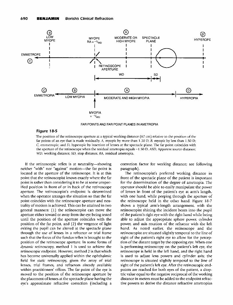
The objective of static retinoscopy is to find the positionof the paraxial far point (punctum remotum) of the eye;this optical theory was initially advocated by Landolt in1878. The reader will remember that the far point is thepoint in space that is optically conjugate to the foveawhen accommodation is relaxed (Figure 18-5). The farpoint of a myopic eye is located in front of (or anteriorto) the eye along the line of sight. Paraxial light diverging from a point source that is placed in the plane ofthe far point of a myopic eye focuses at the retina, andlight diverging from the myopic retina (Le., theretinoscopic fundus reflex) exits the eye convergingtoward a focus in the plane of the far point. In the caseof a hyperopic eye, the far point is located behind (orposterior to) the eye. Paraxial light that converges
Objective Refraction: Retinoscopy, Autorefraction, and Photorefraction Chapter 18 689
AASD (+) WD so
1..1(-----III4-1(-----....·I~
tSPECTACLE
PLANE
t
S;
DIVERGENT BEAM
CONVERGENT BEAMASD (-) SO
1_1(e-----..-I---....~ I~
B
WD
Figure 18-4When the retinoscope and its mirror are tilted through an angle (a), upward, in A, the apparent source ofa divergent beam will move below the line of sight of the eye being analyzed, and the beam entering theeye will intersect the retina above the original line of sight. In B, the retinoscope beam is convergent. Theapparent source will move above the line of sight, and the beam entering the eye at an angle ({3) will intersect the retina below the original line of sight. These effects are independent of the eye's ametropia. ASD,Apparent source distance; WD, working distance; SD, stop distance; s, linear separation between two imagesof the apparent source produced before and after tilt of the retinoscope mirror.
toward a focus in the plane of the far point focuses atthe retina, and light diverging from the hyperopic retinaexits the eye as if it is diverging from the plane containing the far point. In the case of astigmatism,retinoscopy finds two far points per eye: one for each ofthe two primary power meridians. The reciprocal of thedistance along the line of sight in primary gaze position-from the spectacle plane to a far point, inmeters-is the refractive ametropia in diopters.
Basically, the retinoscopist views through the aperture of the retinoscope at a distance of 40 to 100 cmfrom the patient's eye and shines the beam of theretinoscope into the pupil of the patient's eye while thepatient fixates a distant target. To observe the pupillaryreflex of the eye being examined and to simultaneouslyallow fixation of the target by the opposing eye (a formof bi-ocular viewing), the retinoscope and the operatorare typically situated slightly temporal to the line ofsight of the eye being analyzed (Figure 18-6). Roomlighting is reduced so that the operator may obtain ahigh-contrast view of the pupillary reflex; this is alsodone to allow the pupil to dilate so that the pupillaryreflex is somewhat larger and brighter than under
normal room illumination. Topical mydriatic agents areusually not used, but, in some instances (discussedlater), cycloplegia is desirable and is accompanied bymydriasis. By observation of the retinoscopic pupillaryreflex as the meridional axis orientation of the divergentrectangular light beam is altered and as the rectangularbeam is swept across the pupil from side to side alongthe two principal power meridians, the retinoscopist isable to deduce the location of the far point of eachprimary meridian relative to the position of theretinoscope aperture through which he or she isviewing. The attributes of the pupillary reflex that signifythe relative position of the far point are covered in thenext section. However, suffice to say that "with" motionof the pupillary streak reflex-as compared withmovement of the incident divergent rectangular beamindicates a far point location behind the retinoscopeaperture, in the continuum between the operator andinfinity (slightly myopic and emmetropic eyes) orbehind the eye (hyperopic eyes). "Against" motion ofthe streak indicates a far point location between theretinoscope aperture and the patient's eye (moderatelyto highly myopic eyes).
690 BEN.lAMIN Borishs Clinical Refraction
® 0 ®LOW MODERATE OR SPECTACLEMYOPE HYPEROPEMYOPE RA=-l/WDHIGH MYOPE PLANE
I I I I II I I I
eI
EMMETROPEI 1/ I I I
I(,
/~"• I P@ I I I I
I I RETINOSCOPE I I IAPERTURE
II(
WD SD
·H@ ® I 0 @
EMMETROPIA.........-L-O-W-M-Y-O-P-IA--- ....I(...-----------------...~I-----~·~t MODERATE AND HIGH MYOPIA HYPEROPIA
MYOPIA=-1/WD
FAR POINTS AND FAR POINT PLANES IN AMETROPIA
Figure 18-5
The position of the retinoscope aperture at a typical working distance (67 cm) relative to the position of thefar points of an eye that is made residually, A, myopic by more than 1.50 0; B, myopic by less than 1.50 0;C. emmetropic; and D, hyperopic by insertion of lenses at the spectacle plane. The far point coincides withthe aperture of the retinoscope when the residual ametropia equals -1.50 D. ASD, Apparent source distance;WD, working distance; SD, stop distance; RA, residual ametropia.
If the retinoscopic reflex is at neutrality-showingneither "with" nor "against" motion-the far point islocated at the aperture of the retinoscope. It is at thispoint that the retinoscopist knows exactly where the farpoint is rather than considering it to be at some unspecified position in front of or in back of the retinoscopeaperture. The retinoscopist's endpoint is determinedwhen the operator arranges the situation so that the farpoint coincides with the retinoscope aperture and neutrality of motion is achieved. This can be attained in twogeneral manners: (1) the retinoscopist can move theaperture either toward or away from the eye being testeduntil the position of the aperture coincides with theposition of the far point, and (2) the vergence of lightexiting the pupil can be altered at the spectacle planethrough the use of lenses in a refractor or trial framesuch that the focus of the fundus reflex is brought to theposition of the retinoscope aperture. In some forms ofdynamic retinoscopy, method 1 is used to achieve theretinoscopic endpoint. However, method 2 is that whichhas become universally applied within the ophthalmicfield for static retinoscopy, given the array of triallenses, trial frames, and refractors already availablewithin practitioners' offices. The far point of the eye ismoved to the position of the retinoscope aperture bythe placement of lenses at the spectacle plane having theeye's approximate refractive correction (including a
correction factor for working distance; see followingparagraph).
The retinoscopist's preferred working distance infront of the spectacle plane of the patient is importantfor the determination of the degree of ametropia. Theoperator should be able to easily manipulate the powerof lenses in front of the patient's eye at arm's length,with one hand, while peeping through the aperture ofthe retinoscope held in the other hand. Figure 18-7shows a typical arm's-length arrangement, with theretinoscopist shining the incident beam into the pupilof the patient's right eye with the right hand while beingable to adjust the appropriate sphere power, cylinderpower, and axis rotation of the refractor with the lefthand. As noted earlier, the retinoscope and theretinoscopist are situated slightly temporal to the line ofsight of the patient's right eye to allow for the perception of the distant target by the opposing eye. When oneis performing retinoscopy on the patient's left eye, theretinoscope is held in the left hand, and the right handis used to adjust lens powers and cylinder axis; theretinoscope is situated slightly temporal to the line ofsight of the patient's left eye. After the retinoscopic endpoints are reached for both eyes of the patient, a dioptric value equal to the negative reciprocal of the workingdistance in meters must be added to the endpoint refractive powers to derive the distance refractive ametropias
Objective Refraction: Retinoscopy, Autorefraction, and Photorefraction Chapter 18 691
A
PATIENTS EYES
RETINOSCOPE+ APERTURE
~
/RETINOSCOPIST
EDISTANTTARGET
MONOCULAR VIEWINGOF DISTANT TARGET
UNDER BI-OCULAR CONDITIONS(E ~ 3° OR LESS)
RETINOSCOPIST /
B
PATIENTS EYES
EDISTANTTARGET
BINOCULAR VIEWINGOF DISTANT TARGET
DURING RETINOSCOPY(E ~ 10° OR GREATER)
Figure 18-6A, If the operator is seated so that his or her head blocks the view of the distant target for the eye beingtested, the patient must continue to bi-ocularly view at distance with the contralateral eye fixating the target.The patient must disregard the view of the eye being tested. This is sometimes difficult for the patient to doif the tested eye is also the dominant eye. B, Occasionally, then, the retinoscopist must be positioned sufficiently temporal to the line of sight of the eye being analyzed so that binocular vision of the distant targetis allowed. The obliquity of observation (e) should be kept to a minimum.
of the two eyes. For most retinoscopists, the working distance is approximately 67 cm, which necessitates that-1.50 0 be added to each refractive retinoscopic endpoint so that the actual refractive correction can bederived. However, for persons with shorter arms, theworking distance may be closer to 50 cm, whichrequires addition of -2.00 0 to the refractive endpoints.The retinoscopic endpoint should be of zero power inthe case of a -1.50 0 myopic eye tested at a working distance of 67 cm or a -2.000 myopic eye tested at 50 cm.Working distances may vary among operators from40 cm (2.50 D) to 1 m (1.00 D).
To summarize the overall technique of static streakretinoscopy, lenses of varying power are placed in frontof the patient's eye while the retinoscopist analyzes thered fundus reflex through the aperture of a retinoscopeheld at a customary working distance from the spectacle plane. The patient is bi-ocularly viewing a distant
target. The opposing eye is actually fixating the target,while the eye being examined is dazzled by the incidentlight from the retinoscope. In fact, the operator's headwould be blocking the examined eye's view of thedistant target were this eye not dazzled by the brightlight of the retinoscope. However, the operator's eye andthe retinoscope are situated sufficiently temporal to theline of sight of the eye being examined that the line ofsight of the opposing eye is open to the target. Shouldthe operator's eye and retinoscope move directly in frontof the eye being examined, the operator's head may alsoblock the view of the opposing eye, and distance fixation could be lost. It is important that the operator besituated so as to stay out of the way of the fixating eye.
The procedure used to obtain the endpoint is similarto that of "hand neutralization" of spectacle lenses, andit is applied to each primary meridian separately. When"against" motion is recognized for a primary meridian
692 BEN.JAMIN Borishs Clinical Refraction
be confused with another kind ofstraddling that involvescylinder axis.
Figure 18-7
A typical arm's-length pOSltlon, in which theretinoscopist views the patient's left eye with his or herown left eye, holding the retinoscope in the left hand.The retinoscopist uses the right hand to alter the powerand axis of correcting lenses placed at the spectacleplane. The operator's working distance is the distancebetween the retinoscope aperture and that spectacleplane that affords a comfortable and efficient manipulation of power at the spectacle plane. Room lightingwould be dim or dark if retinoscopy was actually beingconducted.
(indicating that a meridian of relative plus power ispresent), minus power is added at the spectacle planeuntil neutralization is achieved. When "with" motion isrecognized (indicating that a meridian of relative minuspower is present), neutralization is achieved throughthe addition of plus power at the spectacle plane. Whenendpoints for both eyes have been established, theymust be corrected by the addition of a dioptric value(usually -1.50 D, but possibly ranging from -1.00 D to-2.50 D) equal to the negative reciprocal of theretinoscopist's working distance in meters.
Neutrality is not an instantaneous point that is easilyidentified but rather a range of uncertainty between perceptible "with" and "against" motions. It is best tobracket midway between just noticeable with and againstmotions to more accurately determine the refractive endpoint. Bracketing can be performed by altering the poweroflenses at the spectacle plane, from lenses that produceperceptible "with" motion to lenses that produce perceptible "against" motion, thereby taking the middle lenspower as the bracketed endpoint. Bracketing can alsobe performed by increasing and decreasing the workingdistance surrounding neutrality, although this is a lesscommonly used method. The reflex motion becomesperceptibly with as the retinoscope aperture is movedslightly toward the patient, and it becomes perceptiblyagainst as the retinoscope aperture is moved slightlyaway from the patient relative to the original working distance at which neutrality was achieved. Bracketing powerby this method is sometimes called straddling, which can
Retinoscopic Fundus Reflex
The light that exits the pupil is that which has beenreflected from the vitreoretinal interface, the retinalpigment epithelium, the choroid, or some combinationthereof. Thus, the fundus reflex is red, although brightportions of the reflex may appear reddish orange or evenyellowish orange in the case of a blonde fundus. Thebright streak that is part of the fundus reflex is locatedat the portion of the fundus that is illuminated by theretinoscope's out-of-focus incident rectangular beam.The streak reflex is a diffuse reflection of light from theilluminated fundus: an elongated patch of fundus thatbecomes the illuminated object for refraction out of theeye. Six major aspects of the reflex indicate the refractivestatus of the eye: (1) brightness, (2) direction of motion,(3) speed of motion, (4) width, (5) definition, and (6)alignment. All of these ean be assessed when the incident retinoscopic beam is moved from one side of thepupil to the other and then back again; this is doneseveral times so that concurrent alterations in thefundus reflex may be observed.
Brightness of the Retinoscopic Fundus ReflexAs has been noted, the reflected light that exits the pupilhas a focal point that lies in front of the eye, as in amyopic primary meridian, or a virtual focal point thatlies in back of the eye, as in a hyperopic primary meridian. At neutrality, the retinoscopic refractive endpoint isreached when the focal point-or far point-has beenmoved to coincide with the aperture of the retinoscope.This occurs when the eye or meridian is naturally myopicby -1.50 D or when the eye or meridian is made to beresidually myopic by -1.50 D after insertion of lenses infront of the eye in a trial frame or refractor (working distance, 67 em). At neutrality, most of the light that exitsthe pupil is focused at the aperture of the retinoscope,and the retinoscopist's eye receives this light for observation: the pupillary reflex appears "bright." If the farpoint is a large distance in front of the retinoscope aperture, as in the case of the highly myopic eye or meridianshown in Figure 18-8, only a fraction of the exiting lightwavefronts move through the aperture of the retinoscopeto be collected by the retinoseopist's eye: the pupillaryreflex appears "dim." Similarly, the reflex will be dimif the eye or the meridian is highly hyperopic. As thefar point is made to approach the aperture of theretinoscope, an increasing proportion of the light wavefronts penetrate the retinoscope aperture. The pupillaryreflex becomes brighter until it reaches its brightest whenneutrality is attained (Figure 18-8).
Illumination (E) of the retinoscope aperture by apoint on the observed fundus reflex is an inverse function of the square of the distance of the far point
Objective Refraction: Retinoscopy, Autorefraction, and Photorefraction Chapter 18 693
RETINOSCOPE APERTURE t:1QI
ATFl POINT
RETINOSCOPE APERTURE 8I70lNT (NEUTRALITY)
1((((CO»» ))) ) )T
IIIIII
FAR POINT PLANE
.......~ DIRECTION OF........... _LIGHT TRAVEL
Figure 18-8The brightness of the fundus reflex is greatest when the retinoscope aperture coincides with the far point ofthe eye. Nearly all of the light making up the fundus image enters the pupil of the retinoscopist's eye. According to the inverse-square law, when the retinoscope aperture and the far point do not coincide, only a portionof the wavefronts will enter the retinoscope aperture to be collected by the retinoscopist's eye.
from the retinoscope aperture according to the inversesquare law:
(Equation 18-4)E = I/(WD+ I/RA)2
where E= illumination at the retinoscope aperture froma point on the fundus reflex at the far-point plane; I =intensity of a point of the fundus reflex when imaged atthe far-point plane; RA = residual ametropia referencedto the spectacle plane or the spectacle plane refraction;and WD = working distance from the retinoscope aperture to the spectacle plane (always +).
The relative brightness of the retinoscopic fundusreflex is, therefore, an indicator of the degree ofametropia or the degree to which the eye has been madeametropic by the insertion of lenses in front of the eye.In some cases, the reflex can be so dim as to be barelyperceptible. This might occur, for instance, whenretinoscopy is begun on an -11.50 D myope or an+8.50 D hyperope and a compensating lens has notbeen placed in front of the eye. By introducing a minuslens of sufficient power in front of the -11.50 D myopiceye or a plus lens of sufficient power in front of the+8.50 D hyperopic eye, the eye is effectively made lessametropic, and the fundus reflex becomes more perceptible. As additional power of the same sign (- or +)is added in the trial frame or refractor, the pupillaryreflex becomes progressively brighter as the far pointmoves closer to the retinoscope, until maximum brightness is obtained at neutrality.
Dimness ofthe retinoscopic fundus reflex is more pronounced in patients with small pupils (hyperopes andelderly patients), which allow less light to enter and exitthe eye, and for patients that have a highly pigmentedretinal epithelia, which reflects less of the incident lightfrom the retinoscope. The fundus reflex may also be dimin cases ofmedia opacification (e.g., when the ocular lensis clouded or has significant brunescens). The brightnessof the fundus reflex may be enhanced by increasing theluminous output of the retinoscope, decreasing theworking distance, dilating the patient's pupil, or enlarging the retinoscope aperture. The streak portion of thereflex may also be made brighter by adjustment of thevergence of the incident beam so as to concentratethe light in the smallest possible area of the fundus.
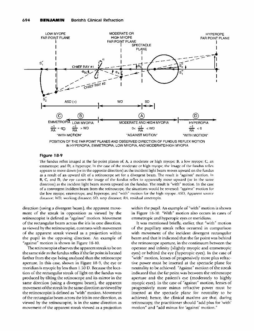
Direction of Motion of the RetinoscopicFundus ReflexThe exit of the fundus reflex from the eye is a separateoptical phenomenon from that of the incident lightdescribed earlier. The most logical explanation for reflexmotion was offered by Laurence and Wood. 13 As can benoted in Figure 18-9, points on the streak reflex originating from the fundus are refocused in the plane of thefar point. The retinoscopist observes the apparent streakto be on the opposite side of the fundus reflex if the farpoint is located between the retinoscope and the eyebeing analyzed. In this case, the eye or meridian ismyopic by more than 1.50 D. Because the location ofthe rectangular streak of light on the fundus is producedby tilting the retinoscope and its mirror in the same
I.......---------I.......;-----......·I~Io @1.......e---------.;~------;l)l~I----""---"""J·~MODERATE AND HIGH MYOPIA HYPEROPIA-1 -1
0< RA < WD RA < 0
"AGAINST MOTION" "WITH MOTION"
s'"1
POSITION OF THE FAR POINT PLANES AND OBSERVED DIRECTION OF FUNDUS REFLEX MOTIONIN HYPEROPIA, EMMETROPIA, LOW MYOPIA, AND MODERATE/HIGH MYOPIA
Figure 18-9The fundus reflex imaged at the far-point planes of, A, a moderate or high myope; B, a low myope; C, anemmetrope; and 0, a hyperope. In the case of the moderate or high myope, the image of the fundus reflexappears to move down (or in the opposite direction) as the incident light beam moves upward on the fundusas a result of an upward tilt of a retinoscope set for a divergent beam. The result is "against" motion. InB, C, and 0, the eye causes the image of the fundus reflex to apparently move upward (or in the samedirection) as the incident light beam moves upward on the fundus. The result is "with" motion. In the caseof a convergent incident beam from the retinoscope, the situations would be reversed: "against" motion forthe low myope, emmetrope, and hyperope, and "with" motion for the high myope. ASO, Apparent sourcedistance; WO, working distance; SO, stop distance; RA, residual ametropia.
direction (using a divergent beam), the apparent movement of the streak in opposition as viewed by theretinoscopist is defined as "against" motion. Movementof the rectangular beam across the iris in one direction,as viewed by the retinoscopist, contrasts with movementof the apparent streak viewed as a projection withinthe pupil in the opposing direction. An example of"against" motion is shown in Figure 18-10.
The retinoscopist observes the apparent streak to be onthe same side as the fundus reflex ifthe far point is locatedfarther from the eye being analyzed than the retinoscopeaperture. In this case, shown in Figure 18-9, the eye ormeridian is myopic by less than 1.50 D. Because the location of the rectangular streak of light on the fundus wasproduced by tilting the retinoscope and its mirror in thesame direction (using a divergent beam), the apparentmovement ofthe streak in the same direction as viewed bythe retinoscopist is defined as "with" motion. Movementof the rectangular beam across the iris in one direction, asviewed by the retinoscopist, is in the same direction asmovement of the apparent streak viewed as a projection
within the pupil. An example of "with" motion is shownin Figure 18-10. "With" motion also occurs in cases ofemmetropic and hyperopic eyes or meridians.
It was mentioned briefly, earlier, that "with" motionof the pupillary streak reflex occurred in comparisonwith movement of the incident divergent rectangularbeam and that it indicated that the far point was behindthe retinoscope aperture, in the continuum between theoperator and infinity (slightly myopic and emmetropiceyes) or behind the eye (hyperopic eyes). In the case of"with" motion, lenses of progressively more plus refractive power must be inserted at the spectacle plane forneutrality to be achieved. "Against" motion of the streakindicated that the far point was between the retinoscopeaperture and the patient's eye (moderately to highlymyopic eyes). In the case of "against" motion, lenses ofprogressively more minus refractive power must beinserted at the spectacle plane for neutrality to beachieved; hence, the clinical maxims are that, duringretinoscopy, the practitioner should "add plus for 'with'motion" and "add minus for 'against' motion."
A
Objective Refraction: Retinoscopy, Autorefraction, and Photorefraction Chapter 18 695
B
Figure '8-' 0A, "Against" motion and, B, "with" motion are demonstrated with a streak retinoscope. The incident beamhas been moved horizontally to the right along the 180 meridian. Note that the perceived fundus streak hasmoved in the direction opposite that of the incident beam relative to the center of the pupil in Aand in thesame direction as the incident beam relative to the center of the pupil in B. The position of the incidentbeam can be noted on the iris outside the pupil, and the position of the perceived fundus streak can benoted in the field of view within the pupil.
Speed of Motion of the RetinoscopicFundus ReflexThe apparent speed of motion of the perceived fundusreflex relative to the angular movement of the incidentbeam is related to the angular motion of the apparentsource for establishing a rectangular streak at theentrance pupil of the eye as well as to the angularmotion of the fundus reflex focused in the plane of thefar point by refraction out of the eye. Although theretinoscopist views the image of an illuminated patchof fundus focused in the plane of the far point, theretinoscopist's visual system projects the image onto thepupil of the eye being analyzed. The greater the angularmovement of the observed image relative to the angularmovement of the incident beam across the iris and pupil(created by tilting the retinoscope mirror), the greaterthe perceived speed of motion of the retinoscopicfundus reflex across the entrance pupil of the eye. 14
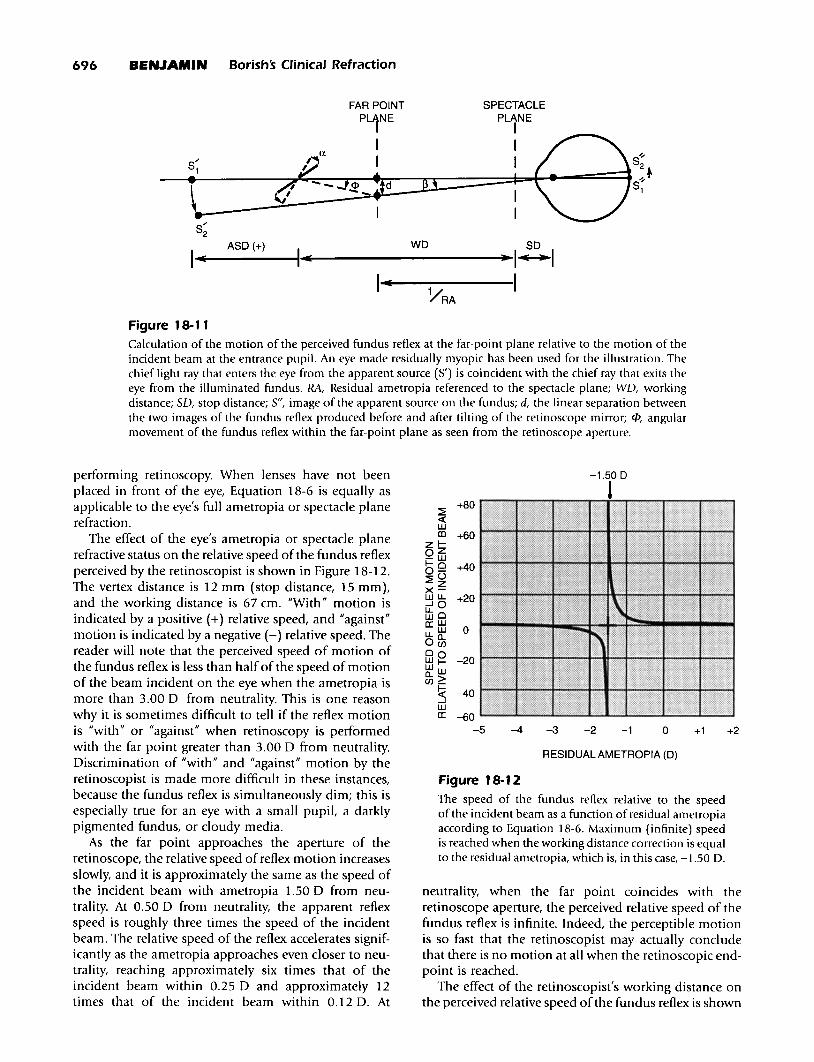
The diagram in Figure 18-11 will now be discussed,in which a divergent retinoscopic beam has beendirected by reflection off of a plane mirror from anapparent source to the fundus of a schematic eye. Theilluminated patch of fundus is refracted back out of theeye to an image in the far-point plane. If the angularseparation of two incident beams before and after tiltingthe retinoscope mirror by an angle a is denoted as fJ andthe angular separation of two fundus reflexes focused inthe plane of the far point before and after tilting isdenoted <I> (as viewed from the retinoscope aperture),then, by trigonometry, the following is given:
(Equation' 8-5)d =tan(fJ) x (SO-liRA) = -tan(<I» x (WO+ liRA)
where RA = residual ametropia referenced to the spectacle plane or spectacle plane refraction; WO = workingdistance from the retinoscope aperture to the spectacleplane; SO = stop distance from the spectacle plane tothe entrance pupil of the eye = vertex distance +3 mm;d = linear separation between two images of the fundusreflex produced before and after tilting the retinoscopemirror; and <1>/fJ = the speed of the observed fundusreflex relative to the speed of the incident beam. Therefore, after simplification and limitation to small anglesin radians, the following is given:
(Equation' 8-6)<I> l-(RA x SO)
fJ (RAxWO)+l
Equation 18-6 gives the degree of angular motion ofthe observed retinoscopic fundus reflex (<I» relative tothe angular motion of the rectangular retinoscope beamthat is incident on the eye (13). One can see that, if theworking distance and the vertex distance are held constant (as typically occurs during static retinoscopy), therelative speed of the reflex motion is controlled by theeye's residual ametropia referenced to the spectacleplane. Residual ametropia is the amount of uncorrectedametropia that exists during the period in which lensesare placed at the spectacle plane during the process of
Figure 18-11Calculation of the motion of the perceived fundus reflex at the far-point plane relative to the motion of theincident beam at the entrance pupil. An eye made residually myopic has been used for the illustration. Thechief light ray that enters the eye from the apparent source (5') is coincident with the chief ray that exits theeye from the illuminated fundus. RA, Residual ametropia referenced to the spectacle plane; WD, workingdistance; SD, stop distance; S", image of the apparent source on the fundus; d, the linear separation betweenthe two images of the fundus reflex produced before and after tilting of the retinoscope mirror; f/>, angularmovement of the fundus reflex within the far-point plane as seen from the retinoscope aperture.
neutrality, when the far point coincides with theretinoscope aperture, the perceived relative speed of thefundus reflex is infinite. Indeed, the perceptible motionis so fast that the retinoscopist may actually concludethat there is no motion at all when the retinoscopic endpoint is reached.
The effect of the retinoscopist's working distance onthe perceived relative speed ofthe fundus reflex is shown
Figure 18-1 2
The speed of the fundus reflex relative to the speedof the incident beam as a function of residual ametropiaaccording to Equation 18-6. Maximum (infinite) speedis reached when the working distance correction is equalto the residual ametropia, which is, in this case, -1.50 D.
RESIDUAL AMETROPIA (D)
-1.50 D
J
+2+1o-1-2
:2+80
«WlD +60
zl-oZ-w1-0 +400-:2°zx-wu. +20...JOltoa:: w
0u. WoBi0 0 -20wI-Wwll..>UJ_
~ -40wa:: -60
-5 -4 -3
performing retinoscopy. When lenses have not beenplaced in front of the eye, Equation 18-6 is equally asapplicable to the eye's full ametropia or spectacle planerefraction.
The effect of the eye's ametropia or spectacle planerefractive status on the relative speed of the fundus reflexperceived by the retinoscopist is shown in Figure 18-12.The vertex distance is 12 mm (stop distance, 15 mm),and the working distance is 67 cm. "With" motion isindicated by a positive (+) relative speed, and "against"motion is indicated by a negative (-) relative speed. Thereader will note that the perceived speed of motion ofthe fundus reflex is less than half of the speed of motionof the beam incident on the eye when the ametropia ismore than 3.00 D from neutrality. This is one reasonwhy it is sometimes difficult to tell if the reflex motionis "with" or "against" when retinoscopy is performedwith the far point greater than 3.00 D from neutrality.Discrimination of "with" and "against" motion by theretinoscopist is made more difficult in these instances,because the fundus reflex is simultaneously dim; this isespecially true for an eye with a small pupiL a darklypigmented fundus, or cloudy media.
As the far point approaches the aperture of theretinoscope, the relative speed of reflex motion increasesslowly, and it is approximately the same as the speed ofthe incident beam with ametropia 1.50 D from neutrality. At 0.50 D from neutrality, the apparent reflexspeed is roughly three times the speed of the incidentbeam. The relative speed of the reflex accelerates significantly as the ametropia approaches even closer to neutrality, reaching approximately six times that of theincident beam within 0.25 D and approximately 12times that of the incident beam within 0.12 D. At
Objective Refraction: Retinoscopy, Autorefraction, and Photorefraction Chapter 18 697
73 em
J~
+30«wen +20
zl-Oz-w1-0 +100-~()
zx-wu. 0...JOu. oWwa: w -10u.o..OC/)
00wI--20Ww
0..>C/)_
~ -30wa:
-400 20 40 60 80 100
WORKING DISTANCE, in em
Figure 18-1 3
The speed of the fundus reflex relative to the speed ofthe incident beam as a function of working distanceaccording to Equation 18-6. The residual ametropiais -1.37 D such that neutrality is achieved at a workingdistance of 73 em.
in Figure 18-13. The vertex distance is 12 mm, and theresidual ametropia chosen for the graph is-1.37 D. The reader will note that the reflex speed is"infinite" when the working distance is such that theretinoscope aperture coincides with the plane of the farpoint. Reasonable variations in the working distancewhile performing retinoscopy (±5 cm) do not muchinfluence the perceived reflex speed or direction unlessthe fundus reflex is near neutrality. With regard to neutrality, relatively small variations in the working distancecan have significant influence on the perception of"with" or "against" motion. Thus, the retinoscopist mustbe sure to keep the head still and the retinoscope aperture in the correct location when the static retinoscopicendpoint is approached by the insertion of lens power atthe spectacle plane (within 0.50 D of neutrality).
The impact of working distance variability is greaterfor retinoscopists using small working distances thanfor those using long working distances. It is, therefore,advantageous for the retinoscopist to use the longestcomfortable working distance to achieve more repeatable endpoints at neutrality. Alterations of vertex distance affect only minor changes of the perceived speedof the retinoscopic fundus reflex, and these can be clinically ignored in this regard.
Width of the Retinoscopic Fundus ReflexThe width of the observed fundus streak is a functionof the ametropia of the eye and the size of the pupil. 15
If the apparent line source of the streak retinoscope is
considered a series of points that are imaged on themyopic schematic eye in Figure 18-14, the size of theblur circle of one of those points on the retina can berelated to pupil size as follows:
(Equation 18-7)B=DxY/X
where B = blur-circle diameter on the retina; D = diameter of the entrance pupil; X = distance from pupil tofocus within schematic eye; and Y = distance from focusto blur circle at retina.
From Figure 18-14, the following is shown:
(Equation 18-8)
X = 1.336 d X Y 1.336--------,an + =---FE- 1 FE+RA
ASD+WD+SD
where FE = refractive power of the eye in diopters;RA = residual ametropia in diopters; ASD = apparentsource distance from apparent source to retinoscopeaperture; WD = working distance from retinoscopeaperture to the spectacle plane; and SD = stop distancefrom spectacle plane to entrance pupil of eye = vertexdistance + 3 mm.
The diameter of the blur circle (B) on the retina canbe calculated, and it can be refracted back out of theschematic eye to the far-point plane. The diameter of theimage of the circle (B') at the far-point plane is, therefore, the following:
(Equation 18-9)
( 1 )B' = D x +1RA· (ASD+ WD+SD)
Furthermore, the diameters of the entrance pupil (Q)and the circle imaged at the far-point plane (0) can bedescribed in terms of their angular sizes as viewed fromthe aperture of the retinoscope. For small angles inradians, the following is given:
(Equation 18-10)D = Q(WD + SD) and B' = 0(WD + SD + l/RA)
Therefore, the observed angular width of the fundusstreak relative to the angular width of the pupil is, forsmall angles in radians, the following:
The effect of the eye's residual ametropia or spectacleplane refractive status on the relative width of thefundus reflex perceived by the retinoscopist (0/Q) can
698 BENJAMIN Borishs Clinical Refraction
} B
BLUR CIRCLE FORMATION ON A HIGHLY MYOPIC RETINA
SPECTACLEPLANE
RETINOSCOPE IAPERTURE I
A
S'
ASO WO so X Y
I"~----I"~-------"-I~ ~ - ~I
B REFRACTION OF THE BLUR CIRCLE TO THE FAR-POINT PLANE
FAR-POINT
RETINOSCOPE PL1NE
APERTURE I
)~------.f{:_0·'I
SPECTACLEPLANE
I
: iB·YRA so X+Y
I....~.....----W-~-~----- ..~II~I • -IFigure 18-1 4Calculation of the width of the perceived fundus streak at the far-point plane relative to the width of theentrance pupil on the basis of the size of the retinal blur circle of a highly myopic eye. A, Light incident fromthe retinoscope. B, Light retro-reflected out of the eye. RA, Residual ametropia; ASD, apparent source distance;WD, working distance; SD, stop distance; 5', apparent source; 5", focus of apparent source in front of thefundus; B, blur circle diameter on the retina; B', blur circle diameter imaged at the far-point plane; D, diameter of the entrance pupil; X distance from the pupil to the focus within the schematic eye; Y, distance fromthe focus to the blur circle at retina; l{J, angular size of the blur circle imaged at the far-point plane as viewedfrom the retinoscope aperture; il, angular size of the entrance pupil as viewed from the retinoscope aperture.
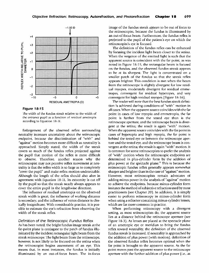
be noted in Figure 18-15 according to Eq. 18-11.The graph has been constructed on the basis that ASO= +33 em (divergent), WO = 67 em, and SO = 15 mm.Although negative values appear in the graph, whichindicates that the fundus streak is reversed, the streakwidth is always perceived as a positive value. When theresidual ametropia is more than ±3.00 0 away fromneutrality, the width of the observed streak is about thesame as the pupil diameter. As neutrality is approachedby the addition of plus power, the streak width slowlybecomes smaller. The perceived width of the fundusstreak is least at a hyperopic point approached byadding plus (with motion). At this point, the far pointcoincides with the apparent source, the source is imagedat the retina, and the diameter of the blur circle is theoretically zero. As neutrality is further approached past
the sharpest point, the width of the streak rapidlyexpands to infinity at neutrality. The retinoscopist thenperceives the pupil to be filled with light.
The reader should note that the fundus streak issharper when approached by the addition of plus powerwhen evaluating with motion. As neutrality isapproached by the addition of minus power when evaluating against motion, the fundus streak remains largerthan the pupil diameter, and it accelerates to an infinitesize at neutrality. To see the extent of the reflex streak,the retinoscopist must move the incident beam acrossthe pupil. At some point-perhaps when the streak isthree times the diameter of the pupil-the width of thereflex streak becomes so large that its extent encompasses the entire pupil, even though the incident beamis moved from one edge of the pupil to the other.
Objective Refraction: Retinoscopy, Autorefraction, and Photorefraction Chapter 18 699
-1.500
~+4
....Iii: +3::::>a..
~ +2LU>-a:::!;(LU +1....II-LULUa:::~
I~ 01-00
3: -1XLU....ILL
-2LUa:::
-3-10 -5 0 +5
RESIDUAL AMETROPIA (D)
Figure 18-1 5The width of the fundus streak relative to the width ofthe entrance pupil as a function of residual ametropiaaccording to Equation 18-11.
Enlargement of the observed reflex surroundingneutrality increases uncertainty about the retinoscopicendpoint, because the discrimination of "with" and"against" motion becomes more difficult as neutrality isapproached. Simply stated, the width of the streakcovers so much of the fundus reflex projected againstthe pupil that motion of the reflex is more difficultto observe. Therefore, another reason why theretinoscopist may not perceive reflex movement at neutrality is that the reflex width is so large as to completely"cover the pupil" and make reflex motion undetectable.Although the length of the reflex should also alter inagreement with Equation 18-11, its extremity is cut offby the pupil so that the streak nearly always appears tocover the entire pupil in the lengthwise direction.
The influence of residual ametropia on the observedstreak width is great; the influence of working distanceis secondary; and the influence of vertex distance is clinically insignificant. With considerable practice, it is possible to estimate the eye's refraction from observing thewidth of the streak reflex.
Definition of the Retinoscopic Fundus ReflexAs has been noted, the bright fundus image streak at thefar-point plane is conjugate to the patch of fundus illuminated by the incident rectangular light beam from thestreak retinoscope. The light beam from the retinoscope,however, is not likely to be focused on the retina whenthe retinoscopist begins assessment of an eye. Thismeans that, in most instances, the fundus is initiallyilluminated by an out-of-focus beam. The in-focus
image of the fundus streak appears to be out of focus tothe retinoscopist, because the fundus is illuminated byan out-of-focus beam. Furthermore, the fundus reflex isprojected to the pupil of the patient's eye on which theretinoscopist's eye is focused.
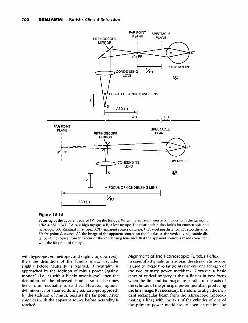
The definition of the fundus reflex can be enhancedby focusing the incident light beam closer to the retina.When the vergence of the emitted light is such that theapparent source is coincident with the far point, as wasnoted in Figure 18-15, the rectangular beam is focusedon the fundus, and the observed fundus streak appearsto be at its sharpest. The light is concentrated on asmaller patch of the fundus so that the streak reflexappears brighter. This condition is met when the beamfrom the retinoscope is slightly divergent for low residual myopes, moderately divergent for residual emmetropes, convergent for residual hyperopes, and veryconvergent for high residual myopes (Figure 18-16).
The reader will note that the best fundus streak definition is achieved during conditions of "with" motion inall cases. When the apparent source coincides with the farpoint in cases of low myopia and emmetropia, the farpoint is further from the tested eye than is theretinoscope aperture, and the retinoscope beam is divergent at the retina; the result is again "with" motion.When the apparent source coincides with the far point incases of hyperopia and high myopia, the far point isbehind the tested eye or between the retinoscope aperture and the tested eye, and the retinoscope beam is convergent at the retina; the result is again "with" motion. Itis common for some retinoscopists to prefer the analysisof "with" motion when the retinoscopic endpoints aredetermined in plus-cylinder form by the addition ofplus power at the spectacle plane. II This is because theretinoscopic fundus reflex generally appears somewhatsharper and brighter than in the case of "against" motion.However, most retinoscopists remain advocates ofadding minus power in the analysis of "against" motionto achieve the endpoints, because minus-cylinder formimitates the method ofsubjective refraction used by mostpractitioners (see Chapter 20). In addition, it is simplyeasier to perform retinoscopy in minus-cylinder formwhen using a refractor containing minus-cylinder lenses,which are far more common in practice.
When performing retinoscopy with a divergentsetting, as most retinoscopists do, the apparent sourcelies at a distance behind the retinoscope aperture (seeFigure 18-3). As lenses are placed at the spectacle planeof an ametropic eye or meridian to bring the fundusreflex toward neutrality, the definition of the observedfundus streak is increased. If neutrality is approached bythe addition of plus power (with motion), definition ofthe observed fundus reflex becomes optimal when thefar point is brought to the apparent source. As the farpoint moves past the apparent source to the retinoscopeaperture with the further addition of plus power (i.e., as
700 BENJAMIN Borishs Clinical Refraction
S~
®
SPECTACLEPLANE
II
S'= FPI
1iii
FAR POINT
PctNE
II
......'""'--"'-. CONDENSING YRALENS
ASD(-)I----~I
__________+I..• W_ D I~I....-----
• FOCUS OF CONDENSING LENS
S~
@
LOW MYOPE
SPECTACLE
PLtNE
I
--"""--- CONDENSINGLENS
zTI-
I-ASD (+)
FAR POINTPLANE
I RETINOSCOPEI MIRROR
I
+---=----------~r_-------~~-s'= FP ,II
Figure 18-16Focusing of the apparent source (S') on the fundus. When the apparent source coincides with the far point,liRA =ASD + WD for, A, a high myope or H, a low myope. The relationship also holds for emmetropia andhyperopia. RA, Residual ametropia; A5D, apparent source distance; WD, working distance; 5D, stop distance;Fp, far point; 5, source; 5", the image of the apparent source on the fundus; z, the vertically adjustable distance of the source from the focus of the condensing lens such that the apparent source is made coincidentwith the far point of the eye.
with hyperopic, emmetropic, and slightly myopic eyes),then the definition of the fundus image degradesslightly before neutrality is reached. If neutrality isapproached by the addition of minus power (againstmotion) (i.e., as with a highly myopic eye), then thedefinition of the observed fundus streak becomesbetter until neutrality is reached. However, optimaldefinition is not attained during retinoscopic approachby the addition of minus, because the far point nevercoincides with the apparent source before neutrality isreached.
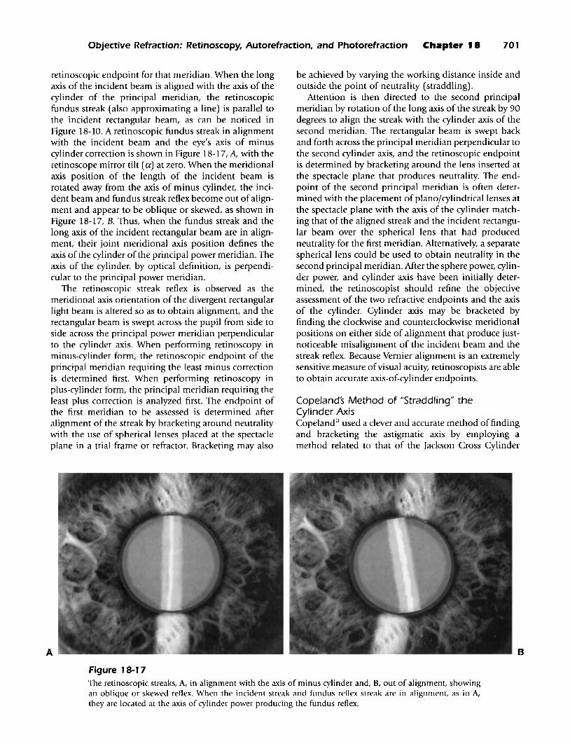
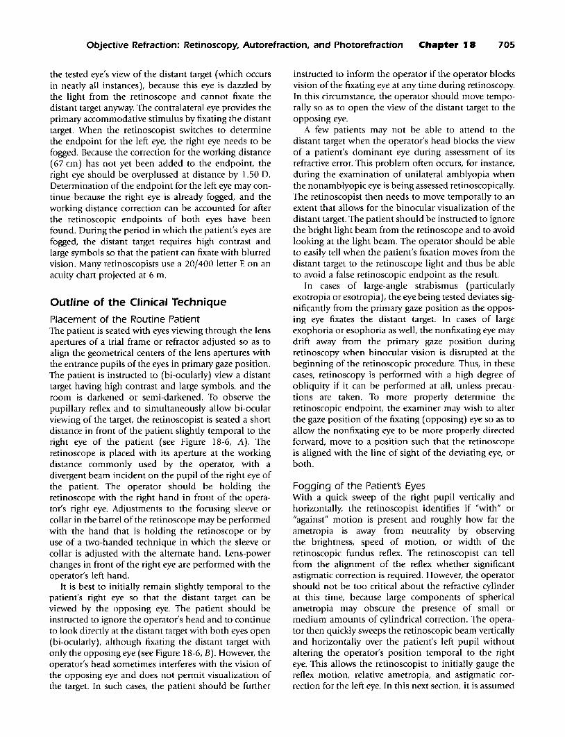
Alignment of the Retinoscopic Fundus ReflexIn cases of astigmatic ametropias, the streak retinoscopeis used to locate two far points per eye: one for each ofthe two primary power meridians. However, a basictenet of optical imagery is that a line is in best focuswhen the line and its image are parallel to the axis ofthe cylinder of the principal power meridian producingthe line image. It is necessary, therefore, to align the incident rectangular beam from the retinoscope (approximating a line) with the axis of the cylinder of one ofthe primary power meridians to then determine the
Objective Refraction: Retinoscopy, Autorefraction, and Photorefraction Chapter 18 701
retinoscopic endpoint for that meridian. When the longaxis of the incident beam is aligned with the axis of thecylinder of the principal meridian, the retinoscopicfundus streak (also approximating aline) is parallel tothe incident rectangular beam, as can be noticed inFigure 18-10. A retinoscopic fundus streak in alignmentwith the incident beam and the eye's axis of minuscylinder correction is shown in Figure 18-17, A, with theretinoscope mirror tilt (a) at zero. When the meridionalaxis position of the length of the incident beam isrotated away from the axis of minus cylinder, the incident beam and fundus streak reflex become out ofalignment and appear to be oblique or skewed, as shown inFigure 18-17, B. Thus, when the fundus streak and thelong axis of the incident rectangular beam are in alignment, their joint meridional axis position defines theaxis of the cylinder of the principal power meridian. Theaxis of the cylinder, by optical definition, is perpendicular to the principal power meridian.
The retinoscopic streak reflex is observed as themeridional axis orientation of the divergent rectangularlight beam is altered so as to obtain alignment, and therectangular beam is swept across the pupil from side toside across the principal power meridian perpendicularto the cylinder axis. When performing retinoscopy inminus-cylinder form, the retinoscopic endpoint of theprincipal meridian requiring the least minus correctionis determined first. When performing retinoscopy inplus-cylinder form, the principal meridian requiring theleast plus correction is analyzed first. The endpoint ofthe first meridian to be assessed is determined afteralignment of the streak by bracketing around neutralitywith the use of spherical lenses placed at the spectacleplane in a trial frame or refractor. Bracketing may also
A
be achieved by varying the working distance inside andoutside the point of neutrality (straddling).
Attention is then directed to the second principalmeridian by rotation of the long axis of the streak by 90degrees to align the streak with the cylinder axis of thesecond meridian. The rectangular beam is swept backand forth across the principal meridian perpendicular tothe second cylinder axis, and the retinoscopic endpointis determined by bracketing around the lens inserted atthe spectacle plane that produces neutrality. The endpoint of the second principal meridian is often determined with the placement of planojcylindrical lenses atthe spectacle plane with the axis of the cylinder matching that of the aligned streak and the incident rectangular beam over the spherical lens that had producedneutrality for the first meridian. Alternatively, a separatespherical lens could be used to obtain neutrality in thesecond principal meridian. After the sphere power, cylinder power, and cylinder axis have been initially determined, the retinoscopist should refine the objectiveassessment of the two refractive endpoints and the axisof the cylinder. Cylinder axis may be bracketed byfinding the clockwise and counterclockwise meridionalpositions on either side of alignment that produce justnoticeable misalignment of the incident beam and thestreak reflex. Because Vernier alignment is an extremelysensitive measure ofvisual acuity, retinoscopists are ableto obtain accurate axis-of-cylinder endpoints.
Cope/ands Method of "Straddling" theCylinder AxisCopeland II used a clever and accurate method of findingand bracketing the astigmatic axis by employing amethod related to that of the Jackson Cross Cylinder
B
Figure 18-1 7The retinoscopic streaks, A, in alignment with the axis of minus cylinder and, B, out of alignment, showingan oblique or skewed reflex. When the incident streak and fundus reflex streak are in alignment, as in A,they are located at the axis of cylinder power producing the fundus reflex.
702 BENJAMIN Borishs Clinical Refraction
technique used in the subjective refraction. For a complete description of the Jackson Cross Cylindertechnique and the optical principles behind it, Chapter20 can be consulted. Briefly, the incident retinoscopicstreak was rotated such that it became aligned 45 degreesoblique to the axis of the correcting cylinder lens beforethe patient's eye. The incident retinoscopic streak wasaligned obliquely, first to one side of the cyl inder axis by45 degrees and then to the other side of the cylinder axisby 45 degrees. Copeland would then compare the speedof rotation and alignment of the fundus reflex streakwith the correcting cylinder axis as he rotated the incident streak from one oblique incident position (45degrees to one side of the cylinder axis) to the other (45degrees to the other side of the cylinder axis). If the correcting cylinder was not perfectly aligned with the astigmatic component of the eye's refractive error, the fundusreflex streak would be misaligned farther away from thecorrecting cylinder axis when the incident beam was atone 45-degree position as compared with the misalignment in the other 45-degree position, and the speeds ofrotation would also be different.
Copeland could then adjust the axis of the correctingcylinder, always rotating the incident streak to 45-degreeobliquity on both sides of the axis, until the fundusstreak reflex became angularly equidistant from thecylinder axis and its speed of rotation identical for bothoblique positions of the incident beam. The accuracy ofthe cylinder axis could be refined even further bymoving the retinoscope aperture inside or outside thepoint of neutrality while simultaneously rotatingthe incident streak to the two oblique positions. Whenthe correcting cylinder axis matched that of the eye'sastigmatism, the fundus reflex streak resulting from one45-degree position would reach neutrality at the samepoint as the other 45-degree position. Copeland bracketed the axis of the correcting cylinder with this method,and he concluded that the correcting cylinder axis thenmatched that of the eye's astigmatic axis. He called thisprocedure straddling, 11 and it is easy to confuse this withthe other kind of straddling, which involves the bracketing of the power correction.
Confused Fundus Reflex and Scissors MotionWhen the refractive status of the eye is different throughone portion of the pupil than through another, theobserved fundus reflex exhibits characteristics of eachdifferent portion of the eye's optical system. One areaof the projected fundus reflex may be neutralized via alens placed at the spectacle plane having a certain refractive power, and a different area of the fundus reflex maybe neutralized with a different refractive power. Basically, each optically separate area within the fundusimage may be focused in a different far-point plane, andthere may be two or more conjugates of the fundus. Thedifferent conjugates can be created by irregular astig-
matism or distorted corneas (kerataconus) and bymonochromatic optical aberrations (especially spherical aberration and coma). The observed fundus reflexmotion will be confused according to the number ofseparate optical areas existing and the degree ofametropic refractive differences between these areas.
Acommonly encountered confused reflex is the resultof the eye's spherical aberration. Particularly in the caseof a large pupiL paraxial rays from an on-axis target traveling through the central pupillary zone likely will notfocus at the same point as do the peripheral rays traveling through the annular zone adjacent to the pupillaryfringe. The same phenomenon occurs for off-axis targetsin the form of coma. The usual situation is encounteredwhen positive (+) spherical aberration and positive (+)coma exist such that the eye's refractive power is greaterthrough the periphery than in the center of the pupil.Therefore, the eye is relatively myopic in the periphery,and it becomes even more myopic peripherally when thepupil dilates in the dark or in response to mydriatic eyedrops. The power change between the center and theperiphery of the pupil may occur continuously from thepupillary center to the edge. The result is a retinoscopicfundus reflex that both appears to move more quicklyin the central pupillary area than in the periphery ofthe pupil as neutrality is approached from the lessminus/more-plus direction and that appears to have aslightly wider streak in the central area than in theperiphery (Figure 18-18). Neutrality is reached first inthe center of the pupiL and more minus is necessary forneutralization of the peripheral reflex. The characteristicmovement of the confused reflex that is observed hasbeen likened to the motion of a pair of scissors-hencethe term scissors motion.
A confused reflex with scissors motion is morecommon and severe in myopic eyes than in hyperopiceyes, eyes with light irises as compared with dark irises,and eyes of young adults as compared with older adults;this is because myopic eyes, eyes with light irises, andyoung adults tend to have larger pupils. Ii> Eyes that areotherwise easily assessed during retinoscopy have pronounced confusion of the reflex when dilated by mydriatic agents. When a confused reflex is encountered, it isbest to neutralize the portion of the fundus reflex thatis projected against the central pupillary area l7 and torely on bracketing to further reduce error in determining the point of neutrality. In fact, it is excellent practiceto always attend to the central reflex and bracket aroundthe endpoint when performing retinoscopy, even ifreflex confusion is not obvious. It will be noted thatmost automated objective refractors sample from thecentral pupil at a diameter of 2.5 to 3.0 mm.
False NeutralityA condition of "false neutrality" may exist when theincident beam is made moderately convergent so that a
Objective Refraction: Retinoscopy, Autorefraction, and Photorefraction Chapter 18 703
Figure 18-1 8
A confused fundus streak reflex as might be seen duringretinoscopy of an eye having a large amount of spherical aberration. The incident streak has been moved horizontally to the right along the 180 meridian. Note thatthe fundus streak is wider centrally and thinner peripherally. Movement of the streak is "with" centrally and"against" peripherally, indicating greater myopia/lesshyperopia in the periphery than in the center of theentrance pupil. Hence, the retinoscopic endpoint wouldbe different centrally than peripherally in this eye.Motion of the incident beam back and forth creates amotion of the fundus reflex similar to that of a pair ofscissors-hence the term scissors motion.
real source is imaged at the entrance pupil of the eyebeing assessed. Essentially, a light source is created atthe entrance pupil of the eye by focusing the retinoscopebeam at the entrance pupil. The conditions are similarto the well-known Maxwellian view,18 and they allowlight to diverge from the exit pupil of the eye such thatthe entire fundus is brightly and uniformly illuminated,regardless of the residual ametropia. The bright fundusreflex is imaged in the far-point plane, and it appears toevenly fill the pupil with light (Figure 18-19). Motionof the fundus reflex is absent. This situation can becreated as the retinoscope beam is altered from divergent to convergent, or vice versa, and it can be confusedwith true retinoscopic neutrality. The effect is independent of refractive error, and it has also been calledincident neutrality. 19 The creation of false neutrality is anexcellent way of setting up a uniform red retroillumination for the visualization of media opacities andrefractile anomalies in the cornea and the crystallinelens during retinoscopy or ophthalmoscopy. In fact,retroillumination through the pupil is achieved inexactly this manner when using the slit-lamp biomicroscope (see Chapter 13).
Figure 18-1 9
The false neutrality is created by focusing the incidentbeam on the entrance pupil of the eye being tested. Notethat the incident beam is well focused on the iris, whichlies in approximately the same plane as the entrancepupil. The pupil is filled with light, and the reflex canbe mistaken for normal retinoscopic neutrality.
Simple Optometry with the RetinoscopeThe ability to determine when the retinoscope's incident beam is focused on the fundus can be used to estimate the ametropia of the eye without lenses placed atthe spectacle plane. If the line target and the image arealigned with the axis of the cylinder of a principalmeridian, the image can be focused sharply on thefundus by alteration of the vergence of the incidentbeam such that the apparent source is at the far pointof the eye (see Figure 18-15). "With" and "against"motion are not assessed, and the retinoscope beam isnot swept across the entrance pupil. If the sleeve orcollar in the barrel of the retinoscope is calibratedaccording to Newton's relationship such that the vergence of light emitted from the condensing lens isknown (given also a known working distance), therefractive correction of the eye can be calculated asfollows:
(Equation 18-12)-liRA = ASD+ WD
where RA = residual ametropia in diopters; ASD =apparent source distance from the apparent source tothe retinoscope aperture (+ for divergent light emittedfrom the retinoscope, - for convergent light); and WD= working distance from the retinoscope aperture to thespectacle plane (always +). The practitioner occasionallyhears of "retinoscopy" endpoints determined byadjustment of the vergence control of the retinoscope instead
704 BENJAMIN Borishs Clinical Refraction
of the alteration of refractive power at the spectacleplane. The method is basically like that of a simpleoptometer, and it was performed by Copeland withthe streak retinoscope. 11 The vergence control of theretinoscope must be calibrated in an exacting manner,and the endpoint is more difficult to discern than intrue retinoscopy. Even so, Weinstock and Wirtschafterothought that simple optometry with the retinoscope wasuseful for the estimation of refractive error in infantsand children.
Control of Accommodation
During retinoscopy, the patient is bi-ocularly (usually)or binocularly (occasionally) viewing a lighted distanttarget in a dark room, and he or she must avoid thepropensity to fixate on the light of the retinoscope thatis being shined into one of the eyes. The room is darkto provide contrast for the fundus reflex and to allowthe pupil to dilate so as to obtain a brighter reflex. Incases of large pupils that exhibit distracting scissorsmotion, the ambient illumination can be increased todecrease the pupil diameter. Should the patient fixateon the retinoscope beam, the accommodation willinduce pupil constriction and simultaneously alter theobserved reflex in terms of such factors as brightness,motion, and streak width. The retinoscopist, therefore,should be able to easily tell when the patient alters fixation from distance too near and when the patientregains attention to the distant target. Localization ofthe retinoscopic endpoint must be suspended while thepatient's attention is removed from the distant target.
Ideally, the accommodative system should be relaxedand should remain static during retinoscopy. However,in reality, the accommodative system is in a tonic stateof minimal flux in even the best of circumstances. Therefore, the retinoscopic endpoint always changes as the farpoint slightly varies position along the line of sight.Subtle changes of accommodative status during retinoscopy can be observed by noting small changes of thepupil diameter and overall changes of fundus reflexcharacteristics related to residual ametropia. Furthermore, the stability of accommodation can be assessedby the retinoscopist when noting the frequency anddegree of observed reflex alterations and pupil-sizechanges. When the accommodative system seems to befluctuating significantly more than normaL the clinicianshould be wary of latent hyperopia, pseudomyopia, andvarious other accommodative abnormalities. It shouldbe noted that accommodative fluctuations result inspherical (not cylindrical) alterations of the observedretinoscopic fundus image. Hence, retinoscopic determination of the cylindrical component of the refractiveerror is more accurate than that of the spherical component. Although the normal accommodative system isnot perfectly relaxed and static, it should be made as
relaxed and static as possible during retinoscopy. Thisis achieved by the "fogging" of the eyes before the determination of the retinoscopic endpoint and by the performance of retinoscopy bi-ocularly or, occasionally,binocularly. Fogging is performed by the addition ofmore-plus/less-minus power at the spectacle planesindependently in front of the two eyes until the residual ametropias are significantly myopic. When foggingis achieved, the eyes will each be out of focus at distanceby at least 1.500 in the two principal meridians inthe direction of more plus/less minus. Any additionalaccommodation makes the patient's distance visionworse.
In practice, the principal meridians of the fixating eyeare overplussed/underminused until the fundus reflexshows "against" motion. The amount of fogging (overplus) is then greater than the correction for workingdistance (>1.50 D). Neutrality is achieved in the nonfixating eye by the addition of less-plus/more-minuspower, as in minus-cylinder form. Attaining neutralityin plus-cylinder form by the addition of more-plus/lessminus power in front of the tested eye may instead beperformed. When the fellow eye is subjected to the incident retinoscopic beam, the fixating eye is now alreadyfogged by 1.50 OS as a result of its far point residingat the retinoscope aperture. Thus, retinoscopy mayproceed in the fellow eye in minus-cylinder form or inplus-cylinder form, as desired, knowing that the fixatingeye is already fogged.
Fogging allows the accommodative system to relaxand to become relatively static in most persons, andit achieves these goals to a lesser extent in personswith latent hyperopia, pseudomyopia, or other accommodative abnormalities. Additionally, bi-ocularityduring retinoscopy helps the accommodative system seta more static tonus at a level that is more consistent withthat of the patient's usual environment. In cases ofintractable hyperopic latency or pseudomyopia, whenfogging and bi-ocularity do not seem to sufficientlyproduce full ametropia, cycloplegia may be attemptedsuch that the accommodative apparatus is temporarilyparalyzed. Cycloplegia tends to eliminate even tonicaccommodation (depending on the efficiency anddosage of the cycloplegic agent used) such that theretinoscopic endpoint is estimated to be 0.50 0 or0.750 more plus than if the usual amount of tonicaccommodation had been present. As previously noted,cycloplegia induces significant reflex confusion (scissorsmotion) as a result of concurrent pupil dilation.
It is important to realize that fogging should bemaintained in the contralateral eye when the other eyeis being tested. 21 Thus, if the right eye is to be analyzedfirst, the left eye is fogged, and the retinoscopic endpoint of the right eye is determined as the left eye viewsthe distant target under conditions ofbi-ocular viewing.It is of little consequence if the operator's head blocks
Objective Refraction: Retinoscopy, Autorefraction, and Photorefraction Chapter 18 705
the tested eye's view of the distant target (which occursin nearly all instances), because this eye is dazzled bythe light from the retinoscope and cannot fixate thedistant target anyway. The contralateral eye provides theprimary accommodative stimulus by fixating the distanttarget. When the retinoscopist switches to determinethe endpoint for the left eye, the right eye needs to befogged. Because the correction for the working distance(67 em) has not yet been added to the endpoint, theright eye should be overplussed at distance by 1.50 D.Determination of the endpoint for the left eye may continue because the right eye is already fogged, and theworking distance correction can be accounted for afterthe retinoscopic endpoints of both eyes have beenfound. During the period in which the patient's eyes arefogged, the distant target requires high contrast andlarge symbols so that the patient can fixate with blurredvision. Many retinoscopists use a 20/400 letter E on anacuity chart projected at 6 m.
Outline of the Clinical Technique
Placement of the Routine PatientThe patient is seated with eyes viewing through the lensapertures of a trial frame or refractor adjusted so as toalign the geometrical centers of the lens apertures withthe entrance pupils of the eyes in primary gaze position.The patient is instructed to (bi-ocularly) view a distanttarget having high contrast and large symbols, and theroom is darkened or semi-darkened. To observe thepupillary reflex and to simultaneously allow bi-ocularviewing of the target, the retinoscopist is seated a shortdistance in front of the patient slightly temporal to theright eye of the patient (see Figure 18-6, A). Theretinoscope is placed with its aperture at the workingdistance commonly used by the operator, with adivergent beam incident on the pupil of the right eye ofthe patient. The operator should be holding theretinoscope with the right hand in front of the operator's right eye. Adjustments to the focusing sleeve orcollar in the barrel of the retinoscope may be performedwith the hand that is holding the retinoscope or byuse of a two-handed technique in which the sleeve orcollar is adjusted with the alternate hand. Lens-powerchanges in front of the right eye are performed with theoperator's left hand.
It is best to initially remain slightly temporal to thepatient's right eye so that the distant target can beviewed by the opposing eye. The patient should beinstructed to ignore the operator's head and to continueto look directly at the distant target with both eyes open(bi-ocularly), although fixating the distant target withonly the opposing eye (see Figure 18-6, B). However, theoperator's head sometimes interferes with the vision ofthe opposing eye and does not permit visualization ofthe target. In such cases, the patient should be further
instructed to inform the operator if the operator blocksvision of the fixating eye at any time during retinoscopy.In this circumstance, the operator should move temporally so as to open the view of the distant target to theopposing eye.
A few patients may not be able to attend to thedistant target when the operator's head blocks the viewof a patient's dominant eye during assessment of itsrefractive error. This problem often occurs, for instance,during the examination of unilateral amblyopia whenthe nonamblyopic eye is being assessed retinoscopically.The retinoscopist then needs to move temporally to anextent that allows for the binocular visualization of thedistant target. The patient should be instructed to ignorethe bright light beam from the retinoscope and to avoidlooking at the light beam. The operator should be ableto easily tell when the patient's fixation moves from thedistant target to the retinoscope light and thus be ableto avoid a false retinoscopic endpoint as the result.
In cases of large-angle strabismus (particularlyexotropia or esotropia), the eye being tested deviates significantly from the primary gaze position as the opposing eye fixates the distant target. In cases of largeexophoria or esophoria as well, the nonfixating eye maydrift away from the primary gaze position duringretinoscopy when binocular vision is disrupted at thebeginning of the retinoscopic procedure. Thus, in thesecases, retinoscopy is performed with a high degree ofobliquity if it can be performed at alL unless precautions are taken. To more properly determine theretinoscopic endpoint, the examiner may wish to alterthe gaze position of the fixating (opposing) eye so as toallow the nonfixating eye to be more properly directedforward, move to a position such that the retinoscopeis aligned with the line of sight of the deviating eye, orboth.
Fogging of the Patients EyesWith a quick sweep of the right pupil vertically andhorizontally, the retinoscopist identifies if "with" or"against" motion is present and roughly how far theametropia is away from neutrality by observingthe brightness, speed of motion, or width of theretinoscopic fundus reflex. The retinoscopist can tellfrom the alignment of the reflex whether significantastigmatic correction is required. However, the operatorshould not be too critical about the refractive cylinderat this time, because large components of sphericalametropia may obscure the presence of small ormedium amounts of cylindrical correction. The operator then quickly sweeps the retinoscopic beam verticallyand horizontally over the patient's left pupil withoutaltering the operator's position temporal to the righteye. This allows the retinoscopist to initially gauge thereflex motion, relative ametropia, and astigmatic correction for the left eye. In this next section, it is assumed
706 BENJAMIN c Borishs Clinical Refraction
that the right eye will be objectively refracted first, whichis typical, and that objective refraction of the left eye willfollow.
If significant "against" motion is present in bothprincipal meridians of each eye, the patient's eyes arealready fogged by an amount greater than the workingdistance correction (>1.50 D). If, on the other hand, oneor both principal meridians in either eye exhibit neutrality or "with" motion, spherical plus power is addedat the spectacle plane to produce residual myopiagreater than the working distance correction (>1.50 Dof myopia). The patient's eyes are fogged when significant "against" motion is seen for each principal meridian of the eyes through the lenses that have been placedat the spectacle plane. Performance of retinoscopy inminus-cylinder form is the natural result of the foggingtechnique that initially places the far point of both eyesbetween the retinoscope and the patient.
Notes on Plus-Cylinder Form, Spot Retinoscopy,and Specular ReflectionsIt is not necessary that both eyes be fogged simultaneously. When one is refracting the right eye, the fixatingleft eye requires fogging, but it is not necessary that theright eye also be fogged, because the right eye cannotfixate during the procedure. Instead, the left eye could beinitially fogged and the right eye refracted in plus- orminus-cylinder form, whichever is desired. When itbecomes the left eye's turn to be refracted, the right eyewill already be in a fogged state. Although it may beeasier to refract here in minus-cylinder form, it would bea simple matter to add sufficient minus spherical powerover the tested eye to be able to approach neutrality bythe addition of plus power in plus-cylinder form.
Therefore, if the operator performs retinoscopy inplus-cylinder form or feels forced into the situation byhaving only a plus-cylinder refractor or trial lens setavailable, it is a simple matter to conduct the clinicalprocedure in plus-cylinder form. Rather than overplus tothe point that "against" motion is achieved (as in minuscylinder form), the operator overminuses the eye beingtested so that "with" motion is achieved. Spherical pluspower is then added at the spectacle plane until neutrality is obtained in the least plus meridian. Next, pluscylinder lenses are added until neutrality is obtained inthe most plus meridian. Alternatively, spherical lensescan be used to neutralize both primary meridians ifa minus-cylinder refractor is being used. As withretinoscopy in minus-cylinder form, the retinoscopistneeds to ensure that the fixating eye is fogged such thataccommodation is optimally relaxed and stabilized.
Although most clinicians would be better off using astreak retinoscope, some are more familiar with spotretinoscopy and would prefer to continue using the spotretinoscope. The optics of spot retinoscopy are the sameas for streak retinoscopy, with the exception that cylin-
der axis and power determinations are more accuratelymade with streak instruments. Therefore, the sameclinical procedures can be used for spot retinoscopyas noted earlier, although meridional axis controls areunnecessary and are not present on spot retinoscopes.
The retinoscopist may note that specular reflectionsfrom the cornea and from the surfaces of the lensesplaced at the spectacle plane may interfere with the visualization of the fundus reflex. The prominent sources ofthe reflections can be the retinoscopic beam and abrightly lighted distant target. In these instances, it maybecome necessary to tilt the lenses in front of thepatient's eye to move the specular lens reflections awayfrom the line of sight of the operator. Alternatively, theobliquity with which the operator views the eye can bealtered such that the line of sight of the operator ismoved away from the specular reflections. The cornealreflex in particular-as well as lens-surface reflectionscan make retinoscopy difficult in cases of small pupils,especially when the fundus reflex is dim. This combination of circumstances could occur, for instance, whena darkly pigmented older person presents for examination with significant ocular lens brunescens. Manyretinoscopists partition the 20/400 letter E on the projected acuity chart with red and green filters. Thisreduces the illumination of the distant target and effectively dims specular reflection of the target from thecornea and the spectacle lens surfaces.
Retinoscopic Endpoints for the Right EyeThe retinoscopist gives attention to the patient's righteye and aligns the length of the incident beam verticallyat axis 090 according to the protractor surrounding thelens aperture of the refractor or trial frame. The beam isswept horizontally, and the fundus streak is observed foralignment and motion relative to the incident beam.The beam is then rotated horizontally to axis 180 andswept vertically so as to again allow observation ofalignment and motion. During the period in which thebeam is being rotated from axis 090 to axis 180, thealignment of the fundus streak is observed with respectto the incident beam. If the incident beam and fundusstreak remain in alignment at all axes, the ametropia isspherical and requires no cylindrical correction. Theretinoscopist would then proceed to neutralize thespherical refractive error by the addition of minus spherical power at the spectacle plane (minus-cylinder form)or by the addition of plus spherical power at the spectacle plane (plus-cylinder form). The spherical power isthen bracketed around neutrality, concentrating on theportion of the fundus reflex projected to the centralpupil, and neutrality is confirmed at axes 090, 180,045,and 135.
If, on the other hand, the fundus streak becomesskewed with respect to the incident beam at axis 090,180, or when rotated in between, the eye's ametropia has
Objective Refraction: Retinoscopy, Autorefraction, and Photorefraction Chapter 18 707
a cylindrical component. In minus-cylinder form, theincident beam is then rotated into alignment with thefundus streak at the axis of cylinder of the least minusmeridian. Minus spherical power is added-or plusspherical power is taken away-at the spectacle planeuntil neutrality is approached as the beam is swept backand forth across the least minus meridian perpendicularto the length of the beam. In plus-cylinder form, theincident beam is then rotated into alignment with thefundus streak at the axis of cylinder of the least plusmeridian. Plus spherical power is added-or minusspherical power is taken away-at the spectacle planeuntil neutrality is approached as the beam is swept backand forth across the least minus meridian perpendicularto the length of the beam. The operator may more critically align the incident beam and reflex at this point byadjustment of the retinoscope's sleeve or collar to alsoobtain a highly defined beam and reflex. The sphericalpower is then bracketed around neutrality, concentratingon the portion of the fundus reflex that is projected tothe central pupil.
In minus-cylinder form, the alignment of the incident beam and fundus streak is brought to the axis ofthe cylinder of the most minus meridian, 90 degreesaway from the least minus meridian. Minus-cylinderlenses are inserted at the spectacle plane, with their axesparallel to the aligned beam and streak. Minus-cylinderpower is then increased until neutrality in the mostminus meridian is approached as the beam is sweptback and forth across the most minus meridian perpendicular to the length of the beam. In plus-cylinderform, the alignment of the incident beam and fundusstreak is brought to the axis of cylinder of the most plusmeridian, 90 degrees away from the least plus meridian.Plus-cylinder lenses are inserted at the spectacle plane,with their axes parallel to the aligned beam and streak.Plus-cylinder power is then increased until neutrality inthe most plus meridian is approached as the beam isswept back and forth across the most plus meridian perpendicular to the length of the beam. The operatorshould at this point more critically align the incidentbeam and reflex by adjustment of the sleeve or collarto also obtain a highly defined beam and reflex. Thecylinder axis is bracketed. The cylindrical power isthen bracketed around neutrality, concentrating on theportion of the fundus reflex that is projected to thecentral pupil. Having reached the endpoint in bothprincipal meridians, the residual ametropia should bespherical. If the retinoscope aperture is now movedslightly toward or away from the patient's right eye, thefundus reflex should exhibit "with" or "against" motion,respectively, in all meridians at the same time.
Retinoscopic Endpoints for the Left EyeThe retinoscopist moves to a seated position on thetemporal side of the patient's left eye, holding the
retinoscope in the left hand at the appropriate workingdistance, and he or she observes through theretinoscope aperture with the left eye while shining theincident beam into the pupil of the patient's left eye.The patient is reminded of precautions concerning theviewing of the distant target in the dark room and toignore the bright light of the retinoscope. Lens-powerchanges in front of the left eye are performed with theoperator's right hand.
The retinoscopist then gives attention to the patient'sleft eye and aligns the length of the incident beam vertically at axis 090 according to the protractor surrounding the lens aperture of the refractor or trial frame. Thebeam is swept horizontally, and the fundus streak isobserved for alignment and motion relative to the incident beam. The beam is then rotated horizontally toaxis 180 and swept vertically so as to again observealignment and motion. During the period in which thebeam is being rotated from axis 090 to axis 180, thealignment of the fundus streak is observed with respectto the incident beam. If the incident beam and fundusstreak remain in alignment at all axes, the ametropiais spherical and requires no cylindrical correction. Theretinoscopist would then proceed to neutralize thespherical refractive error by the addition of minus spherical power at the spectacle plane (minus-cylinder form)or by the addition of plus spherical power at the spectacle plane (plus-cylinder form). The spherical power isthen bracketed around neutrality, concentrating on theportion of the fundus reflex that is projected to thecentral pupil, and neutrality is confirmed at axes 090,180, 045, and 135.
If, on the other hand, the fundus streak becomesskewed with respect to the incident beam at axis 090,180, or when rotated in between, the eye's ametropiahas a cylindrical component. In minus-cylinder form,the incident beam is then rotated into alignment withthe fundus streak at the axis of the cylinder of the leastminus meridian. Minus spherical power is added-orplus spherical power is taken away-at the spectacleplane until neutrality is approached as the beam isswept back and forth across the least minus meridianperpendicular to the length of the beam. In pIus-cylinder form, the incident beam is then rotated into alignment with the fundus streak at the axis of cylinder ofthe least plus meridian. Plus spherical power is addedor minus spherical power is taken away-at the spectacle plane until neutrality is approached as the beam isswept back and forth across the least minus meridianperpendicular to the length of the beam. The operatormay more critically align the incident beam and reflexat this point by adjustment of the retinoscope's sleeveor collar to also obtain a highly defined beam and reflex.The spherical power is then bracketed around neutrality, concentrating on the portion of the fundus reflexthat is projected to the central pupil.
708 BENJAMIN Borishs Clinical Refraction
In minus-cylinder form, the alignment of the incident beam and fundus streak is brought to the axis ofcylinder of the most minus meridian, 90 degrees awayfrom the least minus meridian. Minus-cylinder lensesare inserted at the spectacle plane, with their axes parallel to the aligned beam and streak. Minus-cylinderpower is then increased until neutrality in the mostminus meridian is approached as the beam is sweptback and forth across the most minus meridian perpendicular to the length of the beam. In plus-cylinderform, the alignment of the incident beam and fundusstreak is brought to the axis of cylinder of the most plusmeridian, 90 degrees away from the least plus meridian.Plus-cylinder lenses are inserted at the spectacle plane,with their axes parallel to the aligned beam and streak.Plus-cylinder power is then increased until neutrality inthe most plus meridian is approached as the beam isswept back and forth across the most plus meridianperpendicular to the length of the beam. The operatorshould at this point more critically align the incidentbeam and reflex by adjustment of the sleeve or collarto also obtain a highly defined beam and reflex. Thecylinder axis is bracketed. The cylindrical power isthen bracketed around neutrality, concentrating on theportion of the fundus reflex that is projected to thecentral pupil. Having reached the endpoint in bothprincipal meridians, the residual ametropia should bespherical. If the retinoscope aperture is now movedslightly toward or away from the patient's left eye, thefundus reflex should exhibit "with" or "against" motion,respectively, in all meridians at the same time.
Refinement of the Retinoscopic Endpointsfor Both EyesIt is an excellent idea for the retinoscopist to go backover and refine the endpoints for both principal meridians of each eye to increase the accuracy of the technique. At the same time, the operator can be morecritical about the frequency and degree of accommodative fluctuations that may have occurred during determination of the initial endpoints. The refractiveendpoints in the two eyes may be balanced to compensate for accommodative fluctuations that may havemade the endpoints of one eye too plus or too minusrelative to the other eye. The patient need not berefogged, because the working distance correction is stillin place.
Correction for the Working DistanceThe addition of minus spherical power in a dioptricamount equal to the negative reciprocal of the workingdistance in meters now brings the retinoscopic endpoints to the distance ametropia. For example, -1.50 OSshould be added to the retinoscopic endpoints for a 67cm working distance, or -2.00 OS should be added fora 50-cm working distance. The spherical component of
the retinoscopic endpoint is made more minus, whereasthe cylindrical component remains unchanged.
Some retinoscopists prefer to perform retinoscopyover a separate lens in front of each eye that has the correction of the working distance built in. When one isworking at 67 cm, for example, +1.50-D working lensesare placed in the lens apertures of the trial frame orrefractor. After retinoscopy endpoints are determined,the +1.50-0 lenses are removed (-1.500 is effectivelyadded), leaving the refractive correction in place. Mostrefractors can be ordered with optional working lensesspecific for the performance of retinoscopy at commonworking distances. However, the presence of a separateworking lens introduces an additional and, in the experience of the authors, unnecessary set of specular surfacereflections in front of the patient's eye that hinders visualization of the retinoscopic fundus reflex.
Potential Errors in StaticStreak Retinoscopy
Some of the reasons for error in retinoscopy havealready been mentioned. For instance, variations inworking distance, irregular astigmatism, the presence ofa confused reflex, or false neutrality may create significant error in the retinoscopic endpoint.
Obliquity of ObservationIf the operator's head covers the line of sight of thepatient's tested eye during retinoscopy, the patient's contralateral (opposing) eye should be able to maintain fixation of the distant target in most cases. However, to theextent that the operator must position the aperture ofthe retinoscope temporal to the line of sight, the fundusreflex becomes affected by radial (oblique) astigmatismas a result of the obliquity of observation. The refractivecorrection in the tangential plane, which contains theretinoscope aperture and line of sight of the patient,becomes more myopic/less hyperopic than in the sagittal plane perpendicular to it. Thus, minus-cylinder correction in the vertical axis is a component of theretinoscopic endpoint. The amount of against-the-ruleminus cylinder component increases with observerobliquity, from zero at zero obliquity to approximately0.12 DC x 090 at 5 degrees of obliquity, 0.37 DC x 090at 10 degrees of obliquity, 0.75 DC x 090 at 15 degreesof obliquity, and perhaps 1.37 DC x 090 at 20 degreesof obliquity.22 The influence of obliquity on theretinoscopic endpoint varies among eyes and patients(Figure 18-20).
It is important, therefore, that the retinoscopist minimize the obliquity with which the retinoscopic endpoints are obtained. Obliquity of observation is lessthan 3 degrees if the retinoscopist's head is placed suchthat only the contralateral eye can see the target. A largerobliquity could be justified on the basis of allowing
Objective Refraction: Retinoscopy, Autorefraction, and Photorefraction Chapter 18 709
Figure 18-20The refractive correction in the tangential (horizontal)and sagittal (vertical) planes as a function of the obliquity of observation, as calculated by Bennett for aschematic eye. The difference between the corrections inthe two planes is the amount of radial astigmatisminduced by performing retinoscopy at an angle temporalto the line of sight. (Bennett AG. 1951. Oblique refractionof the schematic eye as in retinoscopy. Optician 15:553.)
binocular fixation of the distant target (e.g., ifretinoscopy was being performed on the dominant eye).Even then, the necessary obliquity should be at most 10degrees. Providing that observer obliquity is minimized,the effect can be ignored in most situations involvingretinoscopy."
Reflection of Light at the OcularReflecting SurfaceIt was noted previously that the ocular reflecting surfaceresponsible for the fundus reflexwas the retina/pigmentepithelium interface but that it was probably referred tothe outer limiting membrane by the wave-guide natureof the layer of rods and cones. There is actually somecontroversy regarding the surface or surfaces that areresponsible for the fundus reflex.The vitreoretinal interface also contributes to the fundus reflex in children andyoung adults. Millodot and O'Leary! felt that the ocularreflecting surface must change positions during life,perhaps being at the vitreoretinal interface in young eyebut posterior to the photoreceptors in the aged eye. Thepresence of multiple reflecting surfaces could be onefactor involved in the degree of endpoint uncertainty,and this also highlights why bracketing is so necessaryfor achieving consistent retinoscopic results.
The retinal layer responsible for the detection of theimage during the subjective refraction must be the outerlimiting membrane, which separates photoreceptorinner segments and nuclei from their photosensitive
outer segments. Visible light rays that strike the outerlimiting membrane are efficiently transmitted to thephotosensitive pigments in the outer segments by awave-guide mechanism. The outer limiting membraneis located approximately 45 urn in front of the pigmentepithelium, but it is approximately 200 urn behind thevitreoretinal interface (see Figure 18-1). Thus, a significant optical disparity is predictable between ametropiafound on the basis of the vitreoretinal interface" andametropia found on the basis of the outer limitingmembrane. Refractive error determined by retinoscopycould be 0.67 OS more hyperopic/less myopic in youngpatients than that determined by a subjective refractionfor this reason. However, the refractive difference shouldbe negligible (0.15 OS) with respect to the minimal separation between the pigment epithelium and the outerlimiting membrane."
The eye is known to have chromatic aberrationslightly more than 1.00 0 when accommodation isrelaxed such that light rays of longer (red) wavelengthsare refracted less strongly than are shorter (blue) wavelengths. The average eye could appear perhaps as muchas 0.50 0 more hyperopic/less myopic when refractivecorrection is determined objectively using reddishorange light from the fundus reflex as compared withrefraction determined subjectively under photopic conditions using white light.
Accommodative StatusNormal fluctuations in accommodative status have beendiscussed. The degree of fogging allowed in retinoscopyis large as compared with that used in the subjectiverefraction. This is because the working distance (67 cmassumed) creates at least 1.50 0 of fogging for the eyeswhen retinoscopy is performed in minus-cylinderfashion. Fogging in the subjective refraction is on theorder of 0.75 O. Chapter 4 shows how too muchfogging opens the accommodative control loop andhow the accommodative system then begins to seek itsresting level. As a result, accommodation sometimes isslightly less relaxed and less stable during retinoscopythan during the subjective refraction.
A major advantage of retinoscopy over the subjectiverefraction and automated forms of objective refractionis the ability of the operator to observe the frequencyand severity of accommodative changes. In effect, theretinoscopist can objectively assess accommodativestability. This is not only important for the determination of the refractive prescription, but it may provideclues about the existence of accommodative problemsrelated to symptoms reported by the patient. Latenthyperopes commonly relax accommodation during theretinoscopic procedure. In these cases, the initial foggingis met with continued accommodative spasm, but,during retinoscopy, the accommodative system maygradually relax. The alert retinoscopist can realize that
710 BENJAMIN Borishs Clinical Refraction
the accommodative system has altered and go back torepeat the retinoscopic findings for either or both eyes.
Subjectivity Versus Objectivity, and the "PlusBias of Retinoscopy"Retinoscopy finds the optical refractive error of the eyeswithout subjective input by the patient. During the subjective refraction, however, input by the patient is usedto arrive at the endpoint. The patient's input may beinfluenced by factors other than optical ametropia.Therefore, the retinoscopy findings and the subjectiverefraction may not be the same, although they are highlycorrelated.25 The retinoscopic findings necessarilyrequire modification during the subjective refraction.
A typical case might result from the determination ofthe refractive status of an eye that has not been previously corrected but that has significant astigmatism.Retinoscopy would likely produce the full optical correction in this case. However, because spectacle lensesmagnify or minify images and create various visual distortions (particularly if the cylinder is oblique), thepatient may not perceive the total cylindrical correctionas being "clear." The patient might perceiver instead,that somewhat less cylinder is appropriate and thusselect a correction on the basis of subjective responsethat has less astigmatic component yet the same equivalent sphere. The patient might do this because, as thetrue optical correction is approached, the visual worldbegins to appear spatially different. The patient's interpretation of the spatial distortion could be that visionis "blurry" when in fact the vision is clear. After all, thispatient has never experienced the spatial distortion produced by spectacles and become accustomed to spectacle vision. The patient may even have meridionalamblyopia. What the patient indicates is "clear" may notbe assumed to have a smaller blur-circle size at the outerlimiting membrane. For this reason, it is incorrect tostrictly compare results of retinoscopy and the subjective refraction and conclude that either is right or wrong.The two tests are actually not measuring the same thing.
Nevertheless, there appears to be a consistent bias ofretinoscopy toward a more hyperopic result by about+0.25 to +0.50 0 as compared with the subjective refraction in youthful eyes. This so-called plus bias ofretinoscopy could be the result of the following: (a) thephysical distance between the effective ocular reflectingsurface and the outer limiting membrane of the retina;(b) the difference in spectral composition of the fundusreflex and room illumination; (c) the difference indegree of fogging applied to retinoscopy as comparedwith the subjective refraction; or a combination thereof.These effects must evidently overcome the myopic tendency created by slight dilation of the pupil in the darkduring retinoscopy. The plus bias found for youthfuleyes at approximately age 10 is linearly reduced withcontinued years of age such that the bias becomes
slightly minus near age 65.1,26 Kragha,27 however, deniesthat the effect of age truly exists. The retinoscopist mayfind through no conscious effort that he or she has gravitated over time to a modification of the technique thatnaturally compensates for the usual plus bias in his orher patient population. As the retinoscopist becomesmore accomplished, the plus bias may fade away as theworking distance is lengthened to attempt equalizationof the objective and subjective findings without alteration of the dioptric working distance correction.
The expert retinoscopist will be able to obtain arepeatability of ±0.25 0 in each principal meridian. 25
Most practiced retinoscopists should attain repeatability of at least ±0.50 0. 28
,29 The axis of cylinder should berepeatable within ±5 degrees and should be better incases of high cylinder power. The practitioner occasionally hears claims by some retinoscopists that theirretinoscopy findings are so accurate that they need notsubjectively refract the patient. The factual claim ofaccuracy may, in fact, be true insofar as the purelyoptical ametropia is concerned. However, as those whohave followed the previous arguments must concluderthe inference is incorrect that accurate retinoscopyresults should be routinely prescribed without subjective modification.
"Dynamic" or "Near" Retinoscopy
Retinoscopy is helpful for the objective determinationof the lag of accommodation during the use of the eyesat near. As noted in Chapters 4,21, and 22/ the normaLunstressed accommodative system does not accommodate such that the retinal conjugate is superimposed onthe near target at which attention is directed. Rather, theaccommodative system in a young adult lags 0.50 to0.750 behind a near target at 40 cm. flaving an accommodative demand of +2.500, the binocular accommodative system normally responds with only 1.75 to2.00 0 of increased plus power. Thus, the near pointor punctum proximum-is usually situated along theline of sight approximately 10 to 17 cm beyond a fixatednear target at 40 cm. The near point is the conjugate tothe retina with accommodation in play when attendingto a near target. Whereas in static retinoscopy the position of the far point (punctum remotum) is determinedwith accommodation relaxed (static), in dynamicretinoscopy, the position of the near point is determined with accommodation functioning (dynamic).
It is important to be able to assess the position of thenear point with respect to a near target, because theinformation can be used to tell if the binocular accommodative system is functioning normally withoutundue stress (lag, +0.50 to +0.75 D). The position of thenear point relative to the near target is described interms of its dioptric distance from the near target. Nearretinoscopy reveals whether the system is lagging off
Objective Refraction: Retinoscopy, Autorefraction, and Photorefraction Chapter 18 711
more than normal (lag, >+0.75 D), showing inadequateaccommodative response possibly as a result of nearesophoria, accommodative insufficiency, or uncorrectedhyperopia. The system could be lagging less thannormal (lag, <+0.50 D) or overaccommodating significantly such that the near point is closer to the patient'seyes than the near target (lag, <0) as a result of nearexophoria or spasm of accommodation. In addition,near retinoscopy reveals the degree to which accommodation is fluctuating when attending to a near target andif the eyes are balanced equally at near. Near imbalancecould be the result of unequal accommodation betweenthe two eyes, unequal accommodative demand as inanisometropia, or improper balance of the distancerefractive correction. Use of accommodative lag in thediagnosis and management of binocular ocular conditions is discussed in Chapters 4, 21, 22, and 30.
Through the years, there have been many techniquesdevised to perform dynamic retinoscopy,30 and clinicaldistillation of these methods has resulted in three basicmethods that are now widely appreciated: theNott method,3! the Bell method, and the monocularestimate method (MEM).,2,33 In each of these methods,the position of the retinal conjugate is found by observing the retinoscopic fundus reflex while the patient isattending to a near target. The retinoscope aperture isheld above or temporal to the near target. The incidentretinoscopic beam is swept across the horizontal meridian of each eye. If the retinoscopist observes "against"motion, the near point for that eye lies in front of theretinoscope, closer to the patient. If the retinoscopistobserves "with" motion, the near point lies in backof the retinoscope, farther from the patient. Whenneutrality is observed, the near point is coincident withthe retinoscope aperture.
The most widely used method is that of Nott/I forwhich the retinoscope aperture is held initially at a distance slightly beyond the near target (Figure 18-21). Theposition of an eye's near point is located by moving theretinoscope aperture toward or away from the eye untilneutrality is reached and bracketed. This is performedfor each eye as the patient attends to the near object,which remains stationary. The accommodativeresponse, in diopters, is subtracted from the accommodative demand (2.500 at 40 cm) to compute theaccommodative lag. A procedure for Nott dynamicretinoscopy is described in Chapter 21.
An alternative method of determining the accommodative lag, also described in Chapter 21, is to initiallyplace the retinoscopic aperture at the plane of the neartarget and to move the target toward (usually, when apositive lag exists) or away from the patient's eyes (occasionally, with a negative lag due to overaccommodation) while the retinoscope remains in its originalposition. This is called Bell retinoscopy. The patient isinstructed to observe the target, and it is moved to that
Figure 18-21
Nott dynamic retinoscopy is performed while thepatient attends to a near target through the distance ornear refraction. The retinoscopist views from a positionabove the near target and slightly temporal to themidline. Initially the retinoscope aperture is locatedbehind the near target, farther from the patient. Theposition of the near point (punctum proximum) is locatedand bracketed by moving the retinoscope aperture awayfrom or toward the patient's eyes. Although dynamicretinoscopy can be performed through the refractor, asshown, a more natural viewing situation can beachieved using a trial frame with trial lenses.
point at which the near point coincides with theretinoscope aperture.
Another alternative method of determining theaccommodative lag, again described in Chapter 21, is tofind the refractive power of a trial lens that moves theposition of the near point to coincide with the finelydetailed, well-illuminated near target. The retinoscopeaperture is positioned in the plane of the near target,and the refractive power of the trial lens that bringsabout bracketed neutrality is the accommodative lag.There are lettered targets that can be applied to the headof a retinoscope (shown in Chapter 21) such that thetarget and retinoscopic aperture are located at the samedistance from the eye. The endpoint is achieved by temporary insertions of trial lenses at the spectacle plane ofthe eye being tested. The retinoscopic aperture andtarget remain in the same plane for the entire procedure.The lenses are quickly interposed before the eye, monocularly, and they are each rapidly removed. The triallenses generally are of low plus power, but they can beof low minus power in cases of significant overaccommodation. As a result, fundus reflex motion must berapidly estimated while each lens is in place for only ashort time «1 second), and at least 3 seconds areallowed between trial lens presentations so that thepatient maintains essential binocular attendance to andfixation of the near target. In this manner, the habitualstates of the accommodative and vergence systems are
712 BENJAMIN- Borishs Clinical Refraction
not disturbed significantly during the procedure. Thismethod is called the MEM of near retinoscopy or,simply, MEM dynamic retinoscopy.
There is a form of retinoscopy called "nearretinoscopy" that should not be confused with themethods ofdynamic or near retinoscopy described here,although the word "near" appears in its name. Themethod is also called "Mohindra retinoscopy" after itsoriginator, 34 and this name avoids the confusion.Mohindra retinoscopy is intended to estimate the refractive status of the eye as if the eye was under cycloplegia.It does not measure accommodative lag, and it is not amethod of dynamic retinoscopy. Mohindra retinoscopyis most useful in pediatric eye care; it is described inChapter 30.
For the three recommended dynamic methods, thenear target should be finely detailed and well illuminated to act as an excellent stimulus for accommodation. The retinoscopist should avoid, as much aspossible, disturbance of the patient's attention to andfixation of the near target with the dazzle of theretinoscope's beam. This can be minimized by reduction of the retinoscope's light intensity and by the rapidestimation of fundus reflex motion, shining theretinoscope beam into the pupil for only short periods.It is important that little uncorrected regular or irregular astigmatism be present, because the techniques donot allow for meridional variations in refractive power.Hence, although dynamic retinoscopy may be performed without optical correction, it is usually performed with the habitual correction in place, with thepatient's current refractive findings at distance in place,or with the patient's near correction in place. Althougha near target at 40 cm is often provided, the techniquesare equally valid at any reasonable near target distance.
Clinical Usefulness of Retinoscopy
Retinoscopy is an extremely useful technique for theeye-care practitioner. It is a way of objectively determining the refractive error that requires knowledge andskill on the part of the operator. Retinoscopy providesa starting point for the subjective refraction and anindependent comparison for the subjective results.Retinoscopy can be more reliable than the subjectiverefraction when patients are unable or unwilling to giveappropriate responses. It can sometimes break downlatent hyperopia or pseudomyopia more readily thancan the subjective refraction.
Expertise in the use of retinoscopy takes considerabletime to acquire, but, after it is acquired, it can dramatically reduce the time necessary for a refractive assessment. Consider the time it would take to arrive at asubjective refraction if there was no starting point or ifthe starting point was not accurate. Hence, retinoscopylowers the cost and increases the accuracy of the eye
examination in ways that cannot be duplicated by anyother device or technique. Signs of accommodative dysfunction, ocular media opacities or refractile anomalies,and certain ocular pathologies, corneal dystrophies, ordegenerations can be identified with the retinoscope,even while it is being used to estimate the optical correction. Importantly, the retinoscopist can actually seethe impact that ocular abnormalities may have on theeye's optical system. In other chapters of this book, different uses of the retinoscope are discussed with regardto the areas of binocular vision, near vision, contact lenspractice, and pediatric eye care. Given the access to trialframes, lenses, and refractors in the modern practitioner's office, the additional cost of a retinoscope atabout $300 seems to be a bargain.
Practitioners have wondered if the computerizedautomated objective refractor will eventually replace theretinoscope. Indeed, the optical principles on whichsome of the automated refractors are based are derivedfrom retinoscopy. Furthermore, autorefractors aredesigned to be operated by office staff to release thepractitioner from this obligation. However, no algorithms of which the authors are aware will account forthe various other abilities of the retinoscope in experthands. The instrument is so versatile that its functionscannot be approached at any price. Automated objectiverefractors, which are more expensive than retinoscopesby factors of 20 to 50, reproduce only the function ofobjectively determining the optical ametropia. Even thisfunction can be inferior to that of expert retinoscopy,because the range of detectable sphere and cylindercorrections is limited, and compensation for accommodative fluctuations or dysfunctions is not possible.Objective autorefractors simply will not work on a substantial number of patients, and they are difficult to useon many other patients. The accomplished operator canusually perform retinoscopy in the same time (or less)that it takes for a technician to perform an automatedrefraction, and far more information can be obtained bythe retinoscopist. It is easy for the practiced clinician tomeasure accommodative lag with a retinoscope. Thus,retinoscopy should remain a primary method of objective refraction for many years to come.
AUTOMATED OBJECTIVEREFRACTION
Automated objective refraction began in the late 1930sand has grown to the point that, today, these instruments are found throughout the world. Commercialization of automated objective refraction was a result ofthe electronic, electro-opticaL and computer revolutions. Far more efficient, compact, and powerful opticaldetectors (photodiodes and charge-coupled deviceICCDI cameras), light sources (high-intensity light and
Objective Refraction: Retinoscopy, Autorefraction, and Photorefraction Chapter 18 713
infrared-emitting diodes), computer displays, microelectronic processors, and computer microprocessorshave become available, especially since the 1970s. Tothe extent that these technological improvements wereincorporated into automated refractors, they madeautomated objective measurements of refractive statusmore repeatable, reproducible, faster, user friendly, andpatient friendly. Indeed, certain automated refractordesigns were not feasible before these basic technological advances.
Collins35 was responsible for the first semiautomatedobjective refractor, called the "electronic refractionometer." However, technological expertise was diverted todifferent areas during World War II, and it was not untilthe 1950s that Campbell again renewed work on autorefractors. In fact, it was this work that energized thedevelopment of automated refractors.36 Soon thereafter,Safir7 automated the retinoscope, and this work led tothe first commercial automated objective refractor, theOphthalmetron, marketed by Bausch & Lomb.38 Thesecond commercial refractor, the 6600 Autorefractor,resulted from the work of Cornsweet and Crane.39 Theirinstrument-which was similar to Campbell's designbecause it was based on the Scheiner principle andBadal optometry-was manufactured by AcuitySystems. In the 1970s, Guilin040 and Munnerlyn41 independently invented an automated objective refractorusing a best-contrast principle with moving gratings thatincorporated some of the features of the earlier Electronic Refractionometer. Munnerlyn's design led to theDioptron, an automated objective refractor manufactured by Coherent Radiation.
The 1980s brought the widespread commercialization of automated objective refractors, often calledmerely autorefractors. The same advances in microprocessors that made personal computers emerge in thisdecade were put to use in automated refractors todecrease their size, enhance their reliability and capability, and allow some new designs to emerge. By 1985,automated keratometers had been added to automaticrefractors, thereby creating combination instruments. Bythe end of the decade, CCD cameras were sufficientlyadvanced and inexpensive enough to be used in automated refractors and automated keratometers as detecting devices. Topcon began offering an autorefractor,corneal topographer, and wavefront refractor combinedinto the same instrument; this idea has now become atrend. Today, in the early 21st century, a new class ofautorefractors known as wavefron refractors or aberrometers has emerged; these instruments use advanced variations of the techniques used in certain of the earlierautorefractors. The new techniques allow for densersampling through the area of the pupil of the eye thanwas previously possible. Hence, they allow for morecomplex aberrations to be diagnosed than the commonspherocylindrical refractive error. Wavefront refractors or
aberrometers will be covered in Chapter 19, althoughthe reader will note the similarity in overall concept withray-deflection autorefractors covered in this chapter.
Of the instruments that have been offered for sale,not all have survived the rigors of an active market.Designs based on the following six general principlesare now commercially available:1. The Scheiner principle2. The retinoscopic principle3. The best-focus principle4. The knife-edge principle5. The ray-deflection principle6. The image-size principleAutorefractors designed to take advantage of these principles are listed in Table 18-1, and they are discussed inthe following sections.
Common Characteristics of AutomatedObjective Refractors
As previously noted, objective refraction techniquesmake use ofdirected and diffuse reflection, or "backscatter," from a small area or areas of the fundus as the secondary source of electromagnetic radiation for theirdetection systems. The operation of an objective refractor depends on characteristics of the secondary sourcethat are used by the detection system. Each type of automated objective refractor assesses different characteristics of the infrared radiation that exits the eye toascertain the eye's refractive status. The methods onwhich the determination of sphere power, cylinderpower, and cylinder axis are based have been partly borrowed from those historically used in optometers(covered in Chapter 1) and in retinoscopy (covered inthe previous section of this chapter). Several of theautorefractors to be discussed use a Badal optometer forthe detection optical path, the source optical path, orboth.
Use of Near-Infrared RadiationAll automated objective refractors have used nearinfrared radiation (NIR) at wavelengths between 780and 950 nm as the primary source of electromagneticradiation, for two important reasons. First, NIR is efficiently reflected back from the fundus. The principalintraocular absorbers of visible light (melanin, hemoglobin, and xanthophil) are relatively ineffective atabsorbing NIR. Thus, more NIR is reflected from thefundus than if visible light or other forms of electromagnetic radiation were used. For instance, the fundusreflects less than 1% of incident green light having awavelength of 550 nm, but it returns more than 9% ofthe NIR at 880 nm. In addition, the media of the normaleye is transparent at the chosen infrared wavelength,having over 90% transmittance, so there is little loss ofradiation before or after reflection by the fundus if the
714 BEN.JAMIN' Borishs Clinical Refraction
TABLE 18-1 Autorefractors and Design Principles
Design Principle Autorefractor
Scheiner's principle
Retinoscopic principles
Best-focus principle
Knife-edge principleRay-deflection principle
Image-size principle
Acuity Systems 6600 (NA)Grand Seiko (RH Burton's BAR 7 in the USA; BAR 8 with AutoK)Nidek (Marco's AR-800 and 820 in the USA; ARK-900 with AutoK)Takagi (not available in the USA)Topcon (NA)
Direction of IftotlonBausch & Lomb Ophthalmetron (NA)
S....d of IftotlonNikon NR-5500 and previous models (NRK-8000 with AutoK)Nikon Retinomax (handheld; also available with AutoK)Tomey TR-lOOO (no longer available in the USA)Carl Zeiss Meditec "Acuitus" (NA)Nidek OPD-Scan (wavefront refraction system with corneal topography system)Coherent Radiation Dioptron (NA)Canon R-l (NA)Humphrey Instruments HARK 599 and previous models (AutoK)Canon R-30 and previous models (RK-3 with AutoK)Hoya (supplied by Canon)Welch-Allyn Sure-Sight (Hartmann-Shack handheld)VISX WaveScan (Hartmann-Shack wavefront refractor)Wavefront Sciences COAS (Hartmann-Shack wavefront refractor)Bausch & Lomb Zywave (Hartmann-Shack wavefront refractor)Alcon LadarWave (Hartmann-Shack wavefront refractor)Topcon KR-9000PW (Hartmann-Shack wavefront refractor with image-size principle refractor
and corneal topographer)Grand Seiko (RH Burton's handheld BAR 600 in USA)Grand Seiko WR 5100K (a "see-through" instrument)Topcon RM-A7000 and previous models (KR-7000S with AutoK and KR-7000P with Corneal
Topography)
NA, Not available; no longer available in the marketplace, although some examples may still be in use.
eye is free of pathology. The second reason for using NIRis that it is essentially invisible to the visual system.Although the primary source of an automated objectiverefractor would be considered very bright were it to becomposed of visible light, the human visual system isinsensitive to NIR and does not react to the presenceof NlR during the diagnostic procedure. The subjectexperiences no photophobia, the pupil of the eye doesnot constrict, and the accommodative system is unaffected by the incident diagnostic NIR radiation.
There are, on the other hand, some disadvantages tothe use of NIR. Because the principal fundus absorbersof visible radiation are not effective absorbers of NIR,NIR is scattered from a volume of fundus tissue extending deep within the choroid, and it cannot be easilylocalized to a single retinal or fundus layer or surface.Although the wave-guide nature of the outer plexiformlayer is significant for light wavelengths in the visiblespectrum, wave guiding is weaker for wavelengths
outside of that range. 6 Thus, the fundus is a more diffusereflector at infrared wavelengths.8 This results in a lessdefined NlR optical image of the illuminated fundusarea as compared with that ofvisible light, on which thediagnosis of refractive status must be based.
Four important areas of evaluation indicate thatoptical radiation returning from the fundus, which isused as the secondary source by objective refractors, maybe logically separated into two components. These areasof evaluation are (1) the analysis of polarization characteristics ofbackscattered radiation at various wavelengthsin the visible and infrared regions8
; (2) the analysis ofthetotal amount of radiation backscattered at various wavelengths in the visible and infrared spectrumsSA2
; (3) theoretical considerations of scattering by tissue of the typefound in the fundus42
; and (4) direct imaging of thefundus when illuminated with thin slits of visible lightand NIR. The first component of the secondary sourcecomes from a thin layer only several microns thick, in
Objective Refraction: Retinoscopy, Autorefraction, and Photorefraction Chapter 18 715
close vicinity to the retinal pigment epithelium (RPE)and the outer segments ofthe visual receptors (see Figure18-1). This layer returns radiation in both the visible andinfrared portions of the spectrum. The percentage ofradiation returned increases as the wavelength increases.The dependence on wavelength is the result of pigmentsin the receptors and macula that have a peak absorbancefor visible light and of melanin in the RPE that absorbsless as the wavelength increases. A sizeable fraction ofthis radiation may be considered to be directed as it isguided by the photoreceptors acting as waveguides.42 Inaddition, this radiation retains almost half of the polarization that it had upon reaching the fundus, whereas therest may be considered to be depolarized. 6 It is mostlikely that scattering from the melanin granules in theRPE causes depolarization and that the waveguide natureof the photoreceptors preserves polarization. This radiation is backscattered from a thin, shallow layer, and thetissue in front of it is clear. There is little opportunity forside scatter. Therefore, this component of the secondarysource may be sharply defined. The second componentof the backscattered optical radiation comes from tissuebetween the RPE and the back surface of the sclera. As aresult of the presence of melanin in the RPE and redblood cells in the choriocapillaris, visible light is efficiently absorbed after it passes into and beyond the RPE.Little if any visible light is returned from this region. Onthe other hand, NIR is not efficiently absorbed. It entersthe RPE, where it can pass all the way to the scleral walLand then it returns back through and past the RPE. NIR isscattered by the diffuse structure through which it passes,and it is scattered in a Lambertian manner42 rather than adirected manner. It returns to the RPE in a diffuse depolarized beam. Thus, the line-spread function describingthe deeply scattered NIR is much broader than the linespread function describing the optical components ofthe eye in terms ofvisible light. When the fundus is illuminated with a sharply defined slit pattern, for instance,the deeply scattered NIR creates a broadened, less-welldefined, secondary image.
The total secondary source may be considered a combination of the radiation backscattered from the thinshallow layer and that backscattered from the thick deeptissue. The result may be seen in fundus images of NIRretinal illumination in the form of focused spots orlines. The overall concept to be drawn from the analysis of backscattered electromagnetic radiation is thatautomated objective refractors using NIR will encountera loss of resolution at the fundus.
There has been a question about which "NIR-reflecting surface" an automated objective refractor finds,although the retina/pigment epithelium interface hasbeen thought to be the most likely average site. Experimental measurements at the visible wavelength of630 nm?-and then at the visible wavelength 543 nmand infrared wavelength 780 nm43-revealed that thesubjective and objective planes of best focus are essen-
tially the same. The planes are located near the anteriorphotoreceptor apertures at the outer limiting membrane. These findings support the view that radiationused by objective refractors is backscattered primarily atthe retina/pigment epithelium interface and that it isthen waveguided to the anterior ends of the photoreceptor apertures, which correspond with the thin,shallow component of the backscattered radiation.
The outer limiting membrane is a logical place fordefined wavefronts to first form. The tissue changes frombeing a turbid, scattering medium followed by waveguiding elements at this interface to a clear, nonscattering medium. Hence, there appears to be a definiteeffective surface that allows objective refraction to be sufficiently repeatable with infrared radiation, such that areliable offset (correction factor) can be programmedinto the operating instrument. The correction factor alsoaccounts for the mean difference of refractive index (n)for the eye between NIR and the peak of the photopicluminosity curve at 555 nm. The mean differencebetween refractive indices at these two wavelengthsaccounts for approximately 0.7 to 1.0 OS. Because a 10%change in this value (0.07 to 0.10 OS) is generally belowthe resolution limit of clinical refraction, the errorincurred by use of the mean index difference is negligible if the autorefractor itself is achromatic (constructedso as to not contribute to chromatic aberration).
All autorefractors make use of visible light for thesupply of a fixation target. Manual objective refractorsmade by Rodenstock and by Zeiss, both from Germany,use visible light in establishing a secondary fundussource and in the determination of the refractive error.However, no autorefractors use visible light to determine the refractive error, because the benefits of invisibility greatly outweigh the disadvantages of NIR.
In summary, the design of an automated objectiverefractor using NIR cannot depend on the presence of afinely detailed secondary source at the fundus, becausesuch sources cannot be formed. Cornsweet and Crane39
pointed out that an automated objective refractor's"signal/noise ratio" can be optimized when the widthof the NIR secondary source approximates the width ofthe eye's NIR optical line-spread function. The secondary source is designed to be as discrete as necessary andyet, with an illuminated fundus area of sufficient size,to return an adequate amount of NIR for processing bythe refractor's detection system. A correction factor mustbe used to compensate for the fact that the average NIRreflecting surface is located posterior to the retinalsurface on which the optimal visual image is focused(the outer limiting layer) and to adjust for the mean difference between refractive indices of NIR and photopicvision created by chromatic aberration of the eye.
Intensity of Primary Source and ReflectionsAlthough a large percentage of NIR is reflected from thefundus, as compared with visible light, only a small
7' 6 BENJAMIN' Borishs Clinical Refraction
amount of the reflected NIR exits the eye. The primaryloss of infrared radiation to detection by the autorefractor is related to the diffuse nature of most of the NIRfundus reflex and the limited area through which radiation must escape through the pupil. The fraction ofincoming NIR that returns from the fundus due todiffuse backscatter fills a large solid angle. This NIR secondary source, therefore, radiates in all directions, butonly a small portion is useful because the exit apertureof the eye (the pupil) subtends only a small solid angle.This represents a loss factor of 100 to 500 for NIR,assuming use of the entire pupil. Autorefractors typically use only a small fraction of the pupil such thateven this loss factor may be an underestimate.
The proportion of the directed fraction of incomingNIR that escapes through the pupil of the eye as it returnsfrom the fundus is much greater than for the diffuse NIR.However, the directed fraction is much less intense thanthe diffuse fraction to begin with, and most of thedirected NIR is then unavailable to the typical autorefractor that samples from only a small fraction of the pupil.
As a result, primary NIR sources of very high intensity are necessary components of automated objectiverefractors. The NIR sources used in automated objective refractors have radiances between 0.5 and 1.5watts/steradian-cm2
• In terms of visible light sources,this would be very bright and unsuitable for most ocularapplications. Because such intense NIR sources arenecessary, the design of a refractor must minimize theeffects of unwanted specular reflections from the opticalsurfaces of the eye and from surfaces in the optical trainof the instrument. Obviously, the refractive elementswithin the instrument should be multicoated, andmirrors should reflect from the front surface so as toreduce or eliminate unwanted reflections. An automatedobjective refractor should have as few "common-path"optical elements as possible to minimize the adverseimpacts of unwanted reflections. Common-path elements are optical components that are in the opticalpaths of both the illumination and the detectionsystems. However, the presence of common-path orcoaxial optics cannot be eliminated from an automatedobjective refractor, because the ocular pupil is the singleroute by which focusable radiation must enter and exitthe interior of the eye. Specular reflections fromcommon-path elements may be attenuated or eliminated by tipping the elements or by using polarizedradiation in combination with polarized light rejectionelements in the detection path. Reflections from thecorneal surface (air/tear-film interface) and the innerlimiting membrane of the retina (vitreoretinaI interface)are of particular importance in the field of automatedrefraction. The "corneal reflex," which is composed ofabout 2.1 % of the radiation incident on the eye, isbrighter than the NIR fundus reflex, and it may easilyinterfere with the detection and analysis of the fundus
reflex. As a result, almost all automated objective refractors contain measures to reduce or eliminate the adverseeffects of the corneal reflex. Many automatic refractordesigns use polarizers to attenuate specular reflections,in general, and these may simultaneously attenuate thecorneal reflex and the vitreoretinal reflex. Aperture stopsor other optical remedies may also be employed; someof these tend to better reduce the confusion of signalwith noise from specular reflections originating near theretina. Individual automated refractors are consideredlater in this chapter, and methods of reducing the effectsof ocular reflections will be discussed as they relatespecifically to the particular refractor designs beingemployed.
Nulling Versus Open-Loop MeasurementPrinciplesAutomatic refractors find the refractive error of the eyeusing either a nulling or an open-loop measurement principle. An instrument using a nulling principle changesits optical system until the refractive error of the eye isneutralized (in other words, until the "null point" isreached). The power that the instrument needed to addto neutralize the refractive error of the eye is taken asthe value of the refractive correction. Retinoscopy, asdescribed earlier, is actually a nulling method of objectively determining refractive status. A "non-nulling"instrument makes its measurement by analyzing thecharacteristics of the radiation exiting the eye, but itdoes not actually correct the refractive error. Because theinstrument does not use its signal to move toward anoptical null, the signal may be called an open-loopsignal, hence the term open-loop principle.
Both approaches have advantages. Nulling instruments can generally be designed to function with highersignal/noise ratios, because conditions can be optimized near the null point. Open-loop instruments aregenerally able to more quickly arrive at the refractivestatus of the eye, because they are not required to altertheir optical systems to move to a null point. The opticalcomponents of open-loop instruments are usually lesscomplicated and require fewer moving parts; thistheoretically increases the functional reliability andlongevity of these instruments. The optical train used formeasurement can, in some autorefractor designs, beused simultaneously for the presentation of a visualtarget to help stabilize fixation and accommodation ofthe eye being tested. This dual function yields savingsin cost, simplification, and size efficiency because of thecommon use of components.
Some refractors determine the full refractive error(sphere and cylinder powers, cylinder axis) of the eye ata single instant. Some refractors determine refractivestatus in a number of different meridians and use thisinformation to derive the full refractive error in severaltenths of a second. "Meridional autorefractors" are most
Objective Refraction: Retinoscopy, Autorefraction, and Photorefraction Chapter 18 717
prevalent in the marketplace, and they may arrive at thefull refractive correction in one of two ways: (1) theprincipal meridians of the eye are found and evaluatedindividually; or (2) the refractive status of three or morefixed meridians are determined (not necessarily principal meridians), and the full refractive correction iscalculated according to the method of Brubaker and colleagues,44 which were subsequently refined by Bennettand Rabbetts.44a The number of measured meridians canbe expanded, thus enhancing the accuracy of thecalculations to the point that all 180 meridians areassessed multiple times in increments of a single degree.
The methods by which refractive error is assessed arespecific to the particular refractor designs employed. Theindividual measurement methods will be discussed asthe automated refractors are separately considered laterin this chapter. In addition, each autorefractor designis programmed to calculate the refractive error on thebasis of an empirical calibration found by the clinicalrefraction of subjects extending over the instrument'sdioptric range.
Resolution of an Effective Fundus ReflectingSurface by Objective RefractionMonochromatic ocular optical aberrations-particularly spherical aberration-can reduce the ability ofautomated objective refractors to find the appropriateendpoint. As was discussed with reference toretinoscopy, variation of the eye's focal distance acrossthe sampled pupillary area reduces the accuracy andresolution of the refractive error. Thus, the opticalsystems of automated objective refractors have beenadjusted to sample over the central portion of the pupil.Most automated refractors sample over a central pupillary diameter of 2.5 to 3.0 mm. Therefore, the patient'spupil size is of little other consequence to most automated objective refractors, unless the pupil becomessmaller than that for which the instrument wasdesigned. Should this occur, the performance of suchrefractors is degraded, often severely. Automated refraction in the presence of pupillary dilation should resultin the same outcome as if the eye had not been dilated,unless the autorefractor samples from the entire pupil(e.g., the Humphrey autorefractor). Pharmacologicalmydriasis has little effect on the objective refraction,except for the lack of tonic accommodation as a resultof simultaneous accommodative paralysis.
The deleterious visual effect ofdiffraction at the pupilbegins to override the beneficial effect of depth of focusat pupil sizes of less than 2.5 mm. However, the effectof diffraction is not an issue for automatic refractors.Nevertheless, small pupil size is a problem, as waspointed out earlier. This could occur in an eye beingtreated with a miotic agent (e.g., pilocarpine), and itwould be in addition to the effect of accommodativespasm as a result of the medication. Small pupils in
an aged patient may also create difficulty for the objective refraction. Fortunately, pinhole pupils create anextended depth of focus such that excellent accuracy ofthe clinical refraction is usually not necessary.
Central vision is most affected by light rays traversingthe central 3 mm of the normal pupil such that the limitation of automated refraction to this central area givesa representative approximation of the pupillary zoneused subjectively by most patients. However, to theextent that a larger proportion ofthe pupil is used duringnormal vision-or that a portion ofthe pupil is used thatis not located at the center-the automated objectiverefraction becomes less related to the subjective refraction. Because spherical aberration is generally positive inthe unaccommodated eye, patients with large pupilsgenerate subjective results that are slightly more minusthan those found with an automated objective refraction. The amount of additional minus power is highlypatient-specific; in generaL it is related to pupil size inexcess of the minimum diameter for which an instrument was designed, because spherical and other monochromatic aberrations vary highly among patients. Inaddition, asymmetrical aberrations specifically reducethe resolution of cylinder power and axis (e.g., whencorneal distortions have been induced by kerataconus,refractive surgery, or ocular trauma).
Automatic objective refractors have several otherobstacles to overcome to accurately assess the refractivestatus of an eye. As has been noted, the secondaryfundus source is diffuse, the amount of NIR exiting thepupil is low, various reflections may collectively reducethe signal/noise ratio, and the depth of retina andchoroid from which radiation is backscattered results inan uncertain approximation of the NIR reflectingsurface. The fact is, however, that, under these difficultconditions, the repeatability (precision) of the automated refractor designs discussed in this chapter can be±0.25 O. This means that, if multiple measurements ofan eye are made over and over again, the standard deviation of the refractive powers in the two primary meridians can reach as low as 0.25 0.45
,46 This is roughly thesame as the resolution of static streak retinoscopy in thehands of an expert operator. The accuracy (validity) ofautorefractive results will be discussed later.
It is a well-known relationship in visual optics that achange of 300 /lm (0.3 mm) in axial length of the eye isequal to about 1.00 0 of refractive error. Thus, the resolution of automated objective refraction and ofstatic streakretinoscopy can be translated into a resolution ofthe axialposition of the fundus reflecting surface of approximately±75 /lm. The axial resolution of objective refractionappears excellent as compared with that of other instruments that have been used to measure the retina. Topographic measurements of the retina using stereoreconstructions can find the surface of the retina witha standard deviation in the range of ±90 to 100 /lm.
718 BENJAMIN Barish's Clinical Refraction
The confocal scanning laser ophthalmoscope can measurethe surface of the retina to a resolution of ±50 ~m,47 butonly when a complicated scanning and averaging methodis employed. The conclusion can be reached that objectiverefraction is capable of repeatability adequate for the axiallocation of a fundus reflecting surface. In fact, pseudotopographical maps have been made of the retinal surfacewith a scanning refractor scheme.48
The resolution of the refractive errors of the two principal meridians contribute to error in the derivation ofcylinder power. Using a standard statistical analysis,therefore, the resolution ofcylinder power should be thesquare root of two (1.414) times that of the meridionalresolution (±0.25 D), or ±0.35 DC. Oversampling bymeasuring multiple meridians in the manner ofBrubaker and colleagues,44 as refined by Bennett andRabbetts,44a or by the performance of multiple measurements on the principal meridians reduces cylinder measurement error, because sphere measurement error isreduced by the same amount. Hence, Malan and Harris,4shaving analyzed data given to them by C. E. McCaghrey,concluded that all of the instruments in their studymeasured cylinder power within approximately ±0.25DC. Winn and colleagues46 also found that cylinderpower was obtainable in their selection of instruments towithin approximately±0.25 DC.
Theoretically, from a statistical point of view, thecylinder power component of refractive status should bemore difficult to resolve during objective refraction thanthe spherical power component. However, as explainedlater, accommodative fluctuations influence the measurement of the sphere power more than the cylinderpower such that, in practice, the accuracy of the spherepower is probably less reliable.49,so Although automatedobjective refractors may be capable of excellent resolution, accommodative fluctuations of the eye being testedreduce the accuracy of these instruments, primarily inthe determination of sphere power. Therefore, Malanand Harris4s found the repeatabilities of a selection ofautorefractors to range from ±0.40 to ±0.64 OS in termsof spherical power. Winn and colleagues46 also foundlarger standard deviations for sphere power as comparedwith cylinder power when human eyes were tested. Thedifferences between instruments were probably relatedto the accommodative uncertainty produced by thevarious fixation devices used by the autorefractors.
The resolution of cylinder power is a function of theautomated refractor's measurement system, and it is essentially fixed. The resolution of the axis ofcylinder, however,depends on the magnitude of cylinder power. As cylinderpower increases, the ability to precisely determine thecylinder axis is enhanced; conversely, the resolution ofcylinder axis degrades as cylinder power is reduced.
Vertex DistanceAutorefractors are constructed such that the full refractive error is determined at the plane of the cornea. This
is often called the "corneal plane refraction," which iseasily converted to the "spectacle plane refraction" atany vertex distance in the manner described in Chapter26. Most modern autorefractors have a default settingbut allow the operator to select from a range of vertexdistances such that the desired spectacle plane refractionis reported.
Accommodation and Fixation ControlThe desired result of an automated refraction is usuallya determination of the refractive error at distance. Theaccommodative system should ideally be placed at rest,with the usual amount of tonus for distance vision. Asduring the performance of static streak retinoscopy,optimal relaxation and stabilization of accommodationcould be achieved by binocularly fogging the patient'seyes into the plus by approximately 0.75 OS. However,most autorefractors are currently monocular devicesand are not equipped to provide binocular or bi-ocularviewing. Therefore, accommodative relaxation andstabilization created by binocularity is not possiblewith current instruments. In most instruments thatattempt to provide some aspects of binocularity, thequality of binocular vision is inferior to that obtainedin the performance of static streak retinoscopy. Anautofogging ability is provided with more sophisticatedinstruments. SI
Most automated objective refractors, for reasons ofcost and simplicity, use a spherical focusing system tobring a monocular fixation target to the approximateplane of the far point. The eye's far point, of course, isoptically relocated by the introduction of sphericalpower to a position within the optical train of theinstrument. The fixation target (visible light) is presented along the same optical axis as the NIR primarysource (invisible) so that, when the patient looks at thetarget, the secondary NIR source is created on thefundus at the fovea. The fixation target is most likely tobe blurred initially, because it will not first be located atthe far point of the eye. As the refractor finds the farpoint of the eye, the dioptric position of the fixationtarget may be adjusted by the instrument to make thedioptric position of the fixation target coincident withthat of the far-point plane. The patient perceives thetarget to become clearer during this process, perhapseven "clear" at the end of the measurement.
Obviously, in cases of highly astigmatic corrections,accommodation/fixation control systems that use onlyspherical corrections are simply not effective. Even whenonly spherical refractive errors are assessed and fogging isintended, monocular fogging is not achieved. 52 Manyautomated refractors tend to approach endpoint soquickly that the fixation target is brought to the far pointfaster than the visual system can respond. In these cases,the refractive status is not able to be evaluated over aperiod sufficient to reduce the endpoint variabilitycreated by accommodative fluctuations, as can be per-
Objective Refraction: Retinoscopy, Autorefraction, and Photorefraction Chapter 18 719
A
formed during static retinoscopy or in the subjectiverefraction (see Chapter 20). Therefore, the state of theaccommodative system during such an automated objective refraction is unknown, and it is certain to vary. Thetwo eyes of a patient must be tested alternately, and theyare likely to be at different accommodative levels whenthe separate clinical refractions are determined. Thedegree of accommodative fluctuation during measurement cannot be qualitatively or quantitatively evaluated.
The phenomenon known as proximal accommodation further confuses the determination of the appropriate refractive correction.49 Designers of automatedrefractors have often dealt with this by using visualfixation targets composed of color photographs ofoutdoor scenes, with prominent central features inthe distance. Accommodation is most relaxed when aprominent feature is of low spatial frequency, when thevisual scene has a wide band of spatial frequencies forobservation, and when the patient identifies the sceneas one typically seen at distance. Natural scenes havethese characteristics, as do some other targets, such asSiemens stars or windmills. The abilities of these targetsto successfully relax and stabilize accommodation when
looking into an instrument under monocular or binocular conditions are suspect, and they depend greatly onthe individual patient. 50
,53
Autorefractors Basedon the Scheiner Principle
The Scheiner principle dates to Christopher Scheiner in1619, and it was used by Thomas Young in his researchabout the origin ofrefractive error. The principle was laterused extensively in a nonautomated manner, before theage ofelectronics, for the assessment of refractive error inthe form of an optometer. The basic principle is coveredin Chapter 1. It was this basic principle that was used forthe infrared refractors developed by Campbell andRobson36 and by Cornsweet and Crane39 and that werefirst marketed by Acuity Systems. Scheiner's principle hasbeen used in more commercial automated refractorsthan has any other basic concept. Acuity Systems, GrandSeiko, Nidek, Tagaki, and Topcon are companies thatcurrently offer (or have offered in the past) automatedrefractors based on the Scheiner principle. Two autorefractors of this type are shown in Figure 18-22.
B
Figure 18-22
Autorefractors based on Scheiner's principle. Nidek autorefractors are marketed as the Marco AR-800, AR820, and ARK-900 in the United States. The Marco AR-820 allows some subjective testing, and the MarcoARK-900 is a combination instrument allowing autorefraction and autokeratometry, although both appearto be similar to the AR-800 shown in A. The BAR 7 autorefractor shown in B, supplied by Grand Seiko andmarketed in the United States by the R.H. Burton Company, is also available in combination with an autokeratometer as the BAR 8. (A, Courtesy of Marco Ophthalmics. B, Courtesy of the R.H. Burton Company.)
720 BEN.JAMIN Borishs Clinical Refraction
Scheiner's principle was originally conceived with theuse of an opaque disk in which two peripheral circularapertures were placed. The apertures were equidistantfrom the center of the disk and opposed from each otherin the same meridian. Light from a primary point sourceat near was collimated through a condensing lens,passed through the "Scheiner's disk," and directedtoward the eye. Two beams of light transmitted throughthe apertures intersected the emmetropic fundus at thesame location. The emmetropic patient would reportthat a single circular patch of light was seen. The secondary fundus source was then single and circular. If theeye refracted the two beams such that they crossed infront of the retina with accommodation relaxed andstable (as in simple myopia), the beams would illuminate two areas of the fundus. The secondary fundussource was doubled such that the two circular fundusareas were separated (medium to high myopia) or partially overlapping (low myopia). In myopia, the illuminated fundus areas were of a "crossed" nature, as theywere on opposing sides of the fundus than when therespective beams entered the eye.
Similarly, in simple hyperopia, the beams intersectedtwo circular patches of the fundus before focus could bereached behind the eye. In hyperopia, the fundus areaswere illuminated in an "uncrossed" manner. A majoradvantage of the use of Scheiner's principle was that anaive observer could more easily identifY when theemmetropic endpoint was reached and could easilybracket around the endpoint. In other words, the use ofthe Scheiner's principle could make the measurement of
refractive error more objective, even when performedsubjectively before automated analyses of fundusreflexes were developed. Subjective refractions ofanimals trained to differentially respond to the perception of one or two objects could be performed with theScheiner principle. It was only logical that Scheiner'sprinciple would be resurrected when rudimentary formsof robotic vision were first applied to detect certain features of the fundus reflex during autorefraction.
Formation of the Secondary Near InfraredRadiation Source, or Fundus ReflexA modem version of Scheiner's principle is accomplished with infrared light-emitting diodes (IR-LEDs)that are optically presented in substitution for the apertures in a Scheiner's disk. To facilitate the measurementof ametropia during autorefraction using IR-LEDs,Scheiner's principle is generally used in conjunctionwith a Badal optometer, the basic principle of which iscovered in Chapter 1. The optical train for incidentradiation (the "source" optical train) in the upper halfof Figure 18-23 reveals how NIR can be presented to theeye by an autorefractor such that a secondary fundussource is formed with a Badal optometer, according toScheiner's principle.
NIR from a pair of IR-LEDs that are spaced equidistant from the optical axis of the source optical train iscollimated by a condensing lens through a circular aperture at A. The sources are fixed on a rotating mount thatallows their orientation to be changed through 180degrees. The IR-LEDs create two collimated beams
SCHEINER PRINCIPLE
FOUR ELEMENT~
DE)t)TECT~R" 'J)\
'~G DETECTOR
./ '-..... IMAGING LENS
/'~ MOVING LENS
RELAYED RETINAL IMAGES
MOVING APERTURE(RETINAL CONJUGATE) __ .' "
~ A.,
SOURCE OPTOMETER LENS~/'
\ . / . /
~ ~ / /'
f=====;,If::i'\ //' :- .,BEAM SPLITTER \\/
RETINAL IMAGE ---- \ t B 8'/'(SECONDARY /' . ~:>--' ;"'_ F
The optical components of a Scheiner's-principle autorefractor based on the Nidek autorefractor. The components are explained in the text.
Objective Refraction: Retinoscopy, Autorefraction, and Photorefraction Chapter 18 721
stemming from a single target (the aperture at A) thatconstitutes the primary NIR source. The target apertureat A is separately adjustable in an anteroposterior (axial)direction to achieve focus at the fundus through theBadal optometer lens placed at B. The Badal lens imagesthe two source IR-LEDs in the entrance pupil after thealignment and adjustment of the entire source opticaltrain to the appropriate central pupillary position andvertex distance by the operator. In this way, the two IRLED images create the two Scheiner apertures in thepupil plane oriented in a single meridian. A fixationtarget using visible light is also introduced through acollateral optical system. Because the secondary focus ofthe Badal lens is at the entrance pupil, the target aperture can be moved with respect to the Badal lens untilit is imaged at the fundus through two different portionsof the pupil and the degree of ametropia is determined.The axial distance of the target aperture away from theprimary focal point of the Badal condensing lens is linearly related to the vergence of NIR entering the eye.
When the aperture is imaged at the fundus, a singlecircular area is illuminated by the two IR-LEDs at or verynear the fovea. However, when not focused at the retina,two circular areas of the fundus are illuminated at orsurrounding the fovea. The fundus illumination isof a "crossed" or "against" nature when the residualametropia in the meridian of an opposed pair of IR-LEDimages is myopic, and the illumination is "uncrossed"or "with" when the residual meridional ametropia ishyperopic. Because the IR-LEDs can be rotated, themeridional orientation of the IR-LEDs is adjustable suchthat the pair of IR-LEDs can be presented in the appropriate meridian. For example, two horizontally opposedIR-LEDs would be necessary to evaluate the meridionalrefractive error in a horizontal power meridian forwhich the cylinder axis approximates 90 degrees.
Analysis of the Secondary Near-InfraredRadiation SourceA collateral "detection" optical train, taken off of thesource optical train by use of a beamsplitter at 0 (lowerhalf of Figure 18-23), is used to image the secondaryfundus source to a special photodetection device. Tworelay lenses, Rl and Rl, create an image of the pupil ofthe eye at position E. The Badal lens at F is located atone focal length from position E and is of the samerefractive power as the Badal lens at B in the sourceoptical train. Returning light passes through a collimating lens G that is slaved to the position of target aperture A in the source optical train. Lens G is positionedsuch that, when the target aperture A images on thefundus, the fundus image created by lens F is coincidentwith the focal point of lens G. Lens G then places thereturning fundus image into collimation, and the detector imaging lens then focuses the image in the plane ofthe photodetection device. When the target aperture is
not conjugate to the retina, the image falling on thephotodetectors is out of focus. However, when therefractive error of the eye is neutralized, the fundusreflex is focused at the photodetection device. Thisarrangement creates a desirable attribute in that theinstrument's sensitivity (signal/noise ratio) peaks at thenull point.
A special aspect of the function of the IR-LEDs is thatthe IR-LEDs flicker on and off alternately. In otherwords, one of the IR-LEDs could be "on" with the otherIR-LED "off" and later the first IR-LED would be "off"and the second IR-LED "on" as the function of theIR-LEDs cycles at a specified frequency; this is calledfrequency modulation of the IR-LEDs. When the targetaperture is in focus on the fundus, the secondary NIRsource is single and, therefore, does not flicker.However, when the secondary NIR source doubles andthe illuminated fundus areas are separated or partiallyoverlapping, the illuminations of the secondary fundusareas flicker. The photodetectors are able to determineif the flicker between illuminated areas of the fundusreflex indicate motion "against" the alternation betweenthe two diodes (residual myopia) or motion "with" thealternation (residual hyperopia) relative to the axialposition of the target aperture with respect to theprimary focal point of the Badal lens. By continuoussampling for the presence of flickering of the fundusillumination at the specified frequency (frequencymodulation), the photodetectors are allowed to drivethe position of the target aperture to the point of neutrality (the null point), where flicker is minimized oreliminated.
A diagram of the special photodetection device at theend of the detection optical train is shown in Figure 1824. The four quadrants of the NIR detection system,labeled I through IV, represent four different photodetectors that are centered on the optical axis of the detection and source optical trains. The horizontal borders ofthe detectors are aligned with the meridian defined bythe two source IR-LEDs. Images of the secondary funduscreated by each IR-LED fall on the detector; these imagesare labeled 1 and 2. Although both images fall on thedetector at once, their respective signals can be separatedfor analysis, because the intensity of each is modulatedat a different frequency. Demodulation by the detectorelectronics allows the signal at the detector to be separated into two signals and each signal to be associatedwith a source. The detector is so constructed and wiredthat it can identify when more NIR falls above or belowhorizontal and when more light falls to the right or leftof vertical. The photodetection system is slaved (synchronized) to the primary IR-LED sources so that itrotates with the sources and maintains meridionalorientation with the IR-LED sources.
Figure 18-24, A, shows a case in which the optometer is positioned at a null position for the examined
722 BEN.lAMIN Borish's Clinical Refraction
II II
image rom LED 1
image rom LED 2image rom LED 2
...........
-'"image rom LED 1
III IV III IV
Meridian nulledAstigmatism present
A Meridian not a principal meridian
Meridian not nulledAstigmatism present
B Meridian not a principal meridian
Figure 18-24The photodetection device of a Scheiner's-principle autorefractor. A, The situation that exists when the meridian under test is nulled so that the source images are aligned horizontally. This meridian is not a principalmeridian, so the source images do not align vertically. B, The situation in which the same meridian is notnulled. LED, Light-emitting diode.
meridian. The eye has been chosen to have an astigmaticrefractive error, and the sampled meridian is not a principal meridian; so, although the images of two sourcesare not separated on the fundus in a direction parallelto the meridian, they are separated at right angles to thatmeridian. Therefore, the right-to-Ieft difference signal ofthe fundus image created by one IR-LED at the detectorequals that created by the other IR-LED, thereby signifying that a null point is attained for the meridian. Asimilar comparison is made between the vertical positions of the fundus images (the upper-to-Iower difference signals). Only when there is vertical alignment ofthe fundus images is a principal meridian being sampled.If residual ametropia is present in the sampled meridian, the image at the photodetectors is doubled horizontally (see Figure 18-24, B). "With" (hyperopic) or"against" (myopic) flicker at the specified frequency canbe deduced by a comparison of the right-to-Ieft difference signals of the two IR-LEDs, and the position ofthe target aperture can be adjusted accordingly untilneutralization is achieved.
On the basis of the upper-to-Iower and left-to-rightdifference signals, the desired direction of rotation ofthe IR-LEDs and photodetectors can be deduced and themeridional orientation adjusted until they are alignedwith a principal meridian. Neutralization of meridionalrefractive error and the null point for axis orientationcan be achieved simultaneously. This process may berepeated for the second principal power meridian, butit is performed so quickly that the interval between thetwo meridional refractive error assessments is clinicallyinsignificant.
In actual clinical operation, the instrument is programmed to derive refractive error consistently and efficiently. Typically, the machine starts with IR-LEDs and
detectors aligned in the l80-degree meridian, and itquickly finds a power null for that meridian by axialadjustment of the target aperture. The IR-LED sourcesand photodetectors are then rotated through 180degrees with the aperture stationary while the signals aremonitored to find the axis positions of the principalmeridians as they are passed during the sweep. The IRLED sources and photodetectors are then rotated to aprincipal meridian, and the target aperture is moved toa null. Finally, the IR-LED sources and photodetectorsare rotated to the other principal meridian, and thetarget aperture is moved to a second null. The targetpositions at null are directly related to the principalmeridional powers, because a Badal optometer systemis used, and the orientation is directly related to the axis.These measured positions allow values for spheres andcylinders to be calculated. Refractors of this type cannull at speeds of up to 100 D/sec.
Unwanted Specular ReflectionsAs can be seen in Figure 18-23, common-path opticalelements include only the ocular surfaces and the beamsplitter at 0, which are potentially capable of causingcoaxial reflections. The major disturbing reflection is thecorneal reflex, which, as Purkinje-Sanson image I,emanates from a position near the entrance pupil.Corneal reflexes of visible light from the fixation targetare inconsequential, because the luminance of the fixation target is much less than that of the NIR sources.Because the autorefractor, as described, projects twobeams of NIR incident on the cornea (from the two IRLEOs), there are actually two corneal reflexes with whichto contend. These reflexes rotate with the IR-LEDs as theinstrument assesses different power meridians, and theyare usually located offof the optic axis of the instrument.
Objective Refraction: Retinoscopy, Autorefraction, and Photorefraction Chapter 18 723
To block these corneal reflexes, an opaque bar isplaced in the optical path at position E, which is thepupil image plane created by the two relay lenses. Thebar is as wide as the images of the corneal reflexes andthus blocks them. The bar is slaved to the mechanismthat rotates the sources so that the light from thecorneal reflexes always images on the bar, no matterwhat the source orientation, and so the light is blockedfrom reaching the detector. Light passing throughportions of the pupil image not blocked by the barreaches the detector, and it is used in the nullingprocess.
This autorefractor design, using the corneal reflexblock, is actually insensitive to specular reflection fromthe vitreoretinal interface. The reason is that the vitreoretinal interface acts as a concave mirror that alters thevergence of the specularly reflected NIR. An image of thetarget aperture is formed by specular reflection at the vitreoretinal interface along the optic axis of the detectionoptical train. Were the image to lie at the position of thecorneal reflex block (an unlikely circumstance), it wouldbe eliminated from the radiation that reaches thephotodetectors. However, if the focused image stemming from the vitreoretinal interface does not lie at theposition of the corneal reflex block (a likely circumstance), the vitreoretinal reflex should be significantlyattenuated anyway. This is because of the bar shape andthe meridional orientation of the corneal reflex block,which tend to roughly match the distribution of radiation in the defocused rays from the two opposed IRLEOs passing through the area of the corneal reflexblock.
SummaryScheiner's-principle autorefractors are nulling refractorsthat optically substitute IR-LEOs for the apertures of atraditional Scheiner's disk. Projection of NIR into theeye, collection of the fundus reflexes emitted fromthe eye, and determination of refractive status areaccomplished using the concept of the Badal optometer. A specialized photodetection device-actually arudimentary form of robotic vision-is employed toanalyze the position of fundus images created by thesource optical train and imaged by the detection opticaltrain at the photodetector. The corneal reflex is removed,and the vitreoretinal reflex is likely attenuated by acorneal reflex block introduced into the path of radiation returning from the fundus. The meridional refractive errors are neutralized (nulled), and the two primarymeridians of the eye are found by a second nullingprocess. The sensitivity (signal/noise ratio) can bebrought to peak at the point of neutralization. Autorefractors based on the Scheiner principle are the mostcommon automated objective refractors available, andthey can reach refractive power endpoints at speedsapproaching 100 O/sec.
Autorefractors Based onRetinoscopic Principles
Aspects of the retinoscopic fundus reflex, as discussed inthe earlier section of this chapter, are related to themeridional refractive corrections of an ametropic eye.Automated evaluations of two of these characteristicshave been applied to the manufacture of autorefractors,which are also called autoretinoscopes: (1) the directionof motion of the observed fundus reflex with respect tothe direction of motion of incident radiation; and (2)the speed of motion of the observed fundus reflex withrespect to the speed of motion of incident radiation. TheOphthalmetron (Bausch & Lomb), which was the firstcommercialized autorefractor, was based on the direction of motion of the fundus reflex (Figure 18-25).Analysis of reflex speed is employed by other autorefractors manufactured by Nikon, and a variant is offeredby Tomey, which is of a simpler construction. Ahandheld autorefractor manufactured by Nikon (theRetinomax) and an autorefractor formerly offered byCarl Zeiss Meditec (Acuitus) also use this principle.
Autoretinoscope Based on Direction of FundusStreak MotionBy now the reader is aware of how an incident rectangular retinoscopic beam can be produced, how thedirection of the fundus streak motion is related tomeridional refractive error, and how the meridional axisorientation of the rectangular beam and perceivedfundus streak are related to the ametropic axis of cylinder. Furthermore, the reader now understands that aBadal optometer can be arranged so as to image thefundus reflex at the plane of a photodetection system.
Figure 18-25The Ophthalmetron by Bausch &. Lomb, circa 1975.(Copyright and courtesy of Bausch &. Lomb.)
724 BENJAMIN Borish~ Clinical Refraction
Thus, as shown in Figure 18-26, the detection opticaltrain of an autoretinoscope can be a Badal optometerhaving a collateral eyepiece reticule (A) that is parfocalwith the Badal lens (B) so that an operator can achievethe appropriate central pupillary position and vertexdistance. A second collateral optical element (C)includes a distance fixation target using visible light.The Ophthalmetron specifically used a "periscope" tocontain the eyepiece reticule, which was inserted intothe detection optical train for alignment by the operator and removed during the assessment of refractiveerror.
However, a third collateral series of elements is thesource optical train of the autoretinoscope, which has arelatively simple optical assembly. The collateral sourceconsists of a retinoscope made to sweep the centralpupillary area with rectangular NIR beams having anadjustable meridional orientation. The Ophthalmetronused a rotating slotted drum with alternating opaqueand transparent apertures turned at a relatively constantrate and only in one direction to create moving rectangular beams of NIR from a source inside the drum. Thisbasic method of creating retinoscopic streaks has beenadopted by almost all subsequent autoretinoscopes andsome nonretinoscopic autorefractors.
The rectangular beams move in a direction perpendicular to their long axes. The beams join the commonportion of the source and detection optical trains, and
they are made incident upon the eye by means of abeam splitter positioned at 0 in Figure 18-26. Hence,the direction of motion of a streak fundus reflex can bedetected when imaged by the Badal lens along theoptical axis of the detection optical train at the conjugate to the retina. In emmetropia, the retinal conjugateis located at the secondary focal point of the Badal lensB. The retinal conjugate is actually the far point of theeye optically relocated by the Badal lens.
The system diagrammed in Figure 18-26 is conceptually similar to that of a normal handheld streakretinoscope. The rectangular incident beams arrive atthe entrance pupil of the eye along the optical axis ofthe instrument and in the line of sight of the eye. Thefundus reflex is also "observed" from a point along theoptical axis of the instrument. The retinoscopist's eyehas been replaced by a photodetection device, shown inFigure 18-26. The photodetection device is composed ofa detector lens E that forms an image of the pupil of theeye on two photodetectors, F and F' , separated by a rectangular space. The long axis of the rectangular space isslaved (synchronized) to the meridian of the long axesof rectangular stripes on the rotating drum so that theborder between photodetectors is always aligned withthe incident rectangular beams.
The anteroposterior (axial) location of the photodetection device is adjustable so that it can be moved tothe far point of the eye to achieve the null point
Figure 18-26The optical components of an autoretinoscope based on the direction of reflex motion (the Ophthalmetron).The alignment periscope and eyepiece (A) are shown withdrawn from the optical train. A beam splitter (D)combines the source and detection optical paths. A moving fundus image (G), created by a Badal optometer lens (B), is in front of the detector lens (E), thereby causing "against" motion on dual detector segments(F and P). The components are explained in the text.
Objective Refraction: Retinoscopy, Autorefraction, and Photorefraction Chapter 18 725
(neutralization), when no movement of the fundusstreak image is observed. The detector lens E, in addition to creating an image of the eye's pupil on the detector surface, serves as the retinoscope aperture. Thus,when the fundus image created by the Badal lens B fallsin the plane of the detector lens E, the fundus reflexstreak appears and disappears in both photodetectorssimultaneously as the incident beam sweeps across theentrance pupil of the eye, thereby indicating a nullsignal (just as stationary motion indicates a null inconventional retinoscopy). If detector lens E is placedin front of the meridional far point (closer to the eye),a "with" motion is encountered. The lower photodetector signals before the upper photodetector, and the photodetection device is driven away from the eye towardthe far point. If the photodetection device is located inback of the meridional far point (farther from the eye),"against" motion is detected. This situation is illustratedin Figure 18-26, in which the fundus image G createdby the Badal lens B forms in front of the detector lensE. The signal of the upper photodetector occurs first, andthe photodetection device is driven toward the eye andthe far point. The axial distance of the photodetectiondevice from the primary focal point of the Badal condensing lens-when the null point is bracketed-islinearly related to the refractive error in the meridianperpendicular to the long axis of the rectangular incident beams. In these respects, autorefractors based ondirection of retinoscopic motion are similar toScheiner's-principle refractors.
In actual clinical operation, the instrument is programmed to consistently derive refractive error. Typically, the machine begins with the incident beam and
the photodetection device aligned to sweep the 180degree meridian, and it quickly finds an approximatepower null by axial adjustment of the photodetectorlocation. The meridional refractive errors are neutralized, whereas the incident beams and photodetectorsare rotated through 180 degrees in increments. Spherepower, cylinder power, and cylinder axis can be derivedfrom the most plus and most minus meridians and theiraxes. The Ophthalmetron required approximately 3seconds to analyze through 180 degrees in incrementsof 1 degree, and it produced a printed recording ofmeridional refractive error versus axis from whichthe operator could derive the full refractive error (Figure18-27). Today, after measuring a sufficient number ofmeridians in a few hundred milliseconds, the data maybe more quickly fitted to a sine-squared function, 54 andthe full refractive correction is derived by computer. Itshould be noted that, although meridional refractiveerror was determined with a nulling process, the principal power meridians were determined with a nonnulling, or open-loop, process.
Autoretinoscope Based on Speed of FundusStreak MotionIt can be deduced from Equation 18-6 that the apparent speed of motion of the retinoscopic fundus reflex isdirectly related to the residual ametropia when theretinoscopic working distance, vertex distance, andsweeping speed of the incident beam are held constant.The time that it takes for the retinoscopic reflex to travelfrom one pupil position to another is inversely proportional to the speed of the reflex and directly proportional to the residual ametropia. Thus, the refractive
Figure 18-27A printed paper recording from the Ophthalmetron indicating the refractive error in each meridian from1 to 180. (Copyright and courtesy of Bausch & Lomb.)
726 BENJAMIN Borishs Clinical Refraction
error can be determined by a calibrated assessment ofthe time it takes for the retinoscopic streak reflex tosweep from one fixed pupil position to another.
Nikon offers an autoretinoscope (Figure 18-28) thatis based on the analysis of reflex speed, which incorporates certain concepts of the Ophthalmetron. It is,perhaps, the simplest of all autorefractor designs (Figure18-29). The source of radiation is a single IR-LEO with aNIR that passes through a collimating lens. The power ofthe collimating lens is selected so that an image of theIR-LEO is created in front of the eye at about its anteriorfocal point at A. This arrangement ensures that a fairlycollimated slit of light falls on the retina, thereby creating the secondary fundus source. The collimated beam ischopped by a rotating slotted drum turning at a constantspeed and in a single direction. The drum produces rectangular beams moving in a direction perpendicular totheir long axes. The NIR beams pass through a beamsplitter at C join the common source/detection opticaltrain, and become incident on the pupil of the eye.Before reaching the eye, however, the incident beamspass through a continuously rotating Pechan prism (B)that cycles the long axis of the rectangular incident
A
beams through all axis meridians. The fixed rate of rotation of the slotted drum-and, therefore, the speed withwhich the incident retinoscopic beams sweep across thepupil-is a critical factor that must be meticulouslymonitored and maintained.
Whereas with the Ophthalmetron neutralization wasreached when the retinoscopic fundus streak reflexwinked on and off on opposing photocells at once (nomotion), nulling is not used for the detection of reflexspeed. Instead, the speed of the moving fundus streakreflex is evaluated by measurement of the time it takesfor radiation to appear on one photocell after it hasappeared on the opposing photocell. Therefore, a Badaloptometer lens is unnecessary, because neutralization ofrefractive error according to the axial position of thereturned fundus image is not attempted.
NIR from the secondary fundus source exits the eye,and, after passing through the Pechan prism (8) and thebeam splitter (C), it is focused by the condensing lens(0) in the detection optical train. The power of this lensis selected so that it creates an image of the pupil of theeye on a four-element photosensor. The four photodetectors are separated and act as masks so that light can
B
Figure 18-28A, The Nikon NR 5500 is an autoretinoscope based on the speed of reflex motion that can also be obtainedin combination with an autokeratometer (the NRK 8000). B, The Retinomax is a handheld Nikon instrument that is also available in a combination form incorporating a handheld autokeratometer (theRetinomax K-plus). (Courtesy of Nifwn Instruments.)
Objective Refraction: Retinoscopy, Autorefraction, and Photorefraction Chapter 18 727
SLIT APERTURED
"-.ROTATING SLOTTED DRUM
FOUR ELEMENT DETECTOR
~
,- - ",',1 ~I
D/ \-<-DETECTOR IMAGING LENS;' "
\ ,/' \/ , ','
" ~
RETINOSCOPIC PRINCIPLE
ROTATING PECHAN PRISM--A / _~- -
EyE......... ~~--o . @)~(~
RETINAL IMAGE(SECONDARY SOURCE) COLLIMATING LENS
Figure 18-29The optical components of an autoretinoscope based on the speed of reflex motion. The components areexplained in the text.
only come from a discrete peripheral area of the pupilto an individual detector. Between the condensing lens(D) and the photosensor is a slit aperture (E) located atthe secondary focal plane of the condensing lens. Thereader may recognize that the secondary focal point ofthe eye (at, in front of, or behind the retina) is conjugate with the center of the slit aperture. The slit apertureis aligned parallel to the long axis of the incident rectangular retinoscopic beam and photosensor. Thisalignment of the slit is critical, because it ensures thatrays of NIR leaving the sampled area of the pupil andreaching the photodetector lie only in a plane that isperpendicular to the meridian being sampled. This, istum, has the effect of making the detection system onlysensitive to the component of light deflection-and,hence, power-in the meridional plane.
For help with understanding this concept, Figure18-30, A, shows a cross section of a myopic eye takenthrough the meridional plane being sampled. The twodetector elements aligned with the meridian sampledare the only ones considered. The only NIR leaving theretina that can reach these detectors is in beams BandB'. These beams are completely defined by apertures
formed by the detector images located in the pupilplane at A, an aperture formed by the image of the slitaperture S. The beams must be parallel to the opticalaxis after exiting the eye, because the slit aperture is inthe focal plane of the detector lens. Because the illuminating streaks, I and 1', move across the retina at a fixedspeed, the time between the extinction of the principalray of beam B and that of beam B' is a measure of theretinal distance 0 (fixed rate multiplied by time equalsdistance).
The distance 0 is directly related to refractive error ascan be seen in the following explanation. In Figure 1830, B, it is seen that the principal rays for detected beamsBand B' pass through the posterior focal point of theeye at the position of slit S. Hence, they exit the eye asif the eye were emmetropic. The dashed rays starting atthe retina midway between the principal rays andexiting the eye at the same points are deflected byamount (j because of the eye's refractive error. Thedeflection is related to the meridional refractive error:
(Equation 18-1 3)
728 BENJAMIN
A
B
Borishs Clinical Refraction
L
____________J~ _
B
.--.--.--.~------------B'
Figure 18-30A, The optical principle of a speed of reflex motion autorefractor. Moving secondary sources (I and I') arecreated by the source. Detected beams (B and B') are defined by the image in the pupil of the detectors (A)and the image of the aperture slit (S), which falls at the posterior focal plane of the eye. The distance betweenthe principal rays of the detected beams (D) is measured by the time between beam occlusions. B, The relationship between the beam deflection (8), which is proportional to refractive error, and distance (D), whichis measured for eye of length (L) and detector aperture spacing (a). 8, Beam deflection in the media ofthe eye.
where a = the distance from the optical axis to the aperture center; 0 = the angle of deflection; and Pm = themeridional refractive error. The deflection anglebetween the rays within the eye, 8, can be approximatedby the following:
(Equation 18-14)0' =D/2L =o/n
where L = the distance from the aperture to the retina;D = distance between illuminated retinal areas; 8 =angle of deflection within the eye; and n = index ofrefraction of the ocular media. As a result, the meridional refractive error is related to the distance betweenthe illuminated retinal areas:
(Equation 18-1 5)Pm = D/2nL
Therefore, because it can be assumed that the valueof L is constant, the meridional refractive error (Pm) isdirectly proportional to the time it takes the movingstreak to pass from one principal beam to the other.
It would be possible to achieve this same effect witha small circular aperture on the optic axis at the samelocation as the slit, but the slit allows more light to reachthe detector and so increases the signal strength. Fromthis point of view, the slit can be thought of as a seriesof circular apertures placed along a line.
It has been noted that the returning fundus streak asseen in the pupil plane would only be aligned with thelong axis of the incident retinoscopic beam when thebeam and streak were simultaneously in the cylinderaxis of a principal power meridian. Should the incidentbeam be swept across an oblique meridian, the returning fundus streak would be skewed with respect to theincident beam. Hence, the image of the streak will be
Objective Refraction: Retinoscopy, Autorefraction, and Photorefraction Chapter 18 729
skewed on the photodetector. This can be seen in Figure18-29, in which the sampled meridian is an obliquemeridian. The two remaining detector elements are usedto take advantage of this skew effect. As can be seen, thetime of occlusion is not the same for these detectors ifthe streak is skewed. This difference signal can be usedto tell if the Pechan prism has been rotated so that theincident beam is aligned with a principal meridian. Inthis way, the principal meridians can be found and theprincipal powers directly measured. This techniquespeeds the refractive process, because fewer meridionalmeasurements are needed, and measurements are notrequired over the entire 180 degrees.
However, the slit aperture provides an alternative wayof finding the final refractive error with this system. Thespeed of the reflex, as measured by the time for thestreak to move from one horizontal detector element tothe other, is proportional to the refractive error of themeridian sampled without the use of any informationfrom the two vertical detectors. This allows only twoelements of the four-element photosensor to sample thespeed of reflex motion in all meridians as the Pechanprism rotates the long axis of the incident beamsthrough 180 degrees. The meridional refractive errorsare computed and may be quickly fitted to a sinesquared function, 54 from which the full refractive correction is derived. It should be noted that meridionalrefractive error and the principal power meridians areeach determined with an open-loop process.
An Alternative Design Based on Reflex SpeedAn autoretinoscope offered by Tomey (Figure 18-31)is similar in construction to that just discussed. Thesimpler Tomey design eliminates the necessity for thePechan prism. The slots in the rotating drum are obliqueto the direction of movement, with half of the slots fixedin the 4S-degree meridian and the others fixed in the13S-degree meridian. The slit aperture is replaced by acircular aperture, and the Pechan prism is removed.Otherwise, the optical trains are similar to those shownin Figures 18-29 and 18-30. The entrance pupil isimaged on a photodetection device consisting of fourseparated elements arranged in a square. The electroniccircuitry measures the time between the appearances ofsignals on opposing detectors. Thus, the device can beconsidered to be determining the speed of the fundusreflex movement between four different discrete areas ofthe entrance pupil of the eye.
Although the streaks created by the slots in the drummove across the retinal surface in a horizontal directiontipped at oblique angles, they may be thought of asmoving in a direction perpendicular to their edges; theyare then seen to move at right angles to one another.So, with this point of view, there is a system with twoorthogonal streaks. So that the aperture in the focalplane of the detector condensing lens may work for
Figure 18-31The Tomey TR-IOOO autoretinoscope, which is basedpartially on speed of reflex motion and partially on theray deflection principle. Once offered in the UnitedStates, this autorefractor is still available internationally.(Courtesy of Tomey Corporation.)
both streaks as just described, the slit is replaced with acircular aperture. Figure 18-30, A, illustrates the situation for either of the two perpendicular meridiansdefined by the orientation of the slots. The detectorelements are arranged in a square, with a pair alignedwith each of the two slot orientations. This arrangementis capable of measuring the power in two meridians.However, this is not enough information to findthe refractive error of the eye, because there is noway of knowing if these two meridians are principalmeridians.
The additional information is supplied by makinguse of the fact that the streak is skewed if an obliquemeridian is measured. More subtle use of this information is made than in the case of the Nikon refractor.It was noted that the returning fundus streak wouldonly be aligned with the long axis of the incidentretinoscopic beam when the beam and the streak weresimultaneously in the cylinder axis of a principal powermeridian. If the incident beam is swept across a meridian oblique to that of the principal meridians, thereturning fundus streak is skewed with respect to theincident beam. To make use of the skew effect, the timebetween occlusions is measured for the other incidentbeam, which is the beam that moves at right angles tothe original beam. This fundus streak is also skewed ifthe meridian through which it moves is not a principalmeridian. The time difference measures what may becalled the cross-meridional power for the meridian of
730 BENJAMIN Borishs Clinical Refraction
motion. This power is oriented at 45 degrees to themeridian of motion, and it is the power that causes thebeam to skew.
With the addition of two cross-meridian measurements, there are now two meridional powers and twocross-meridional powers that can be used to find therefractive error of the eye. First, the spherical equivalentof the refractive correction can be found by averagingany two refractive errors found in meridians at rightangles to each other. Second, the difference of the twomeridional powers is taken, resulting in a cylinderpower oriented with axes parallel to the measured meridians. Third, the difference of the two cross-meridionalpowers is taken, resulting in a cylinder power orientedat 45 degrees oblique to the measured meridians.The square root of the sum of the squares of these twocylinder powers is the resultant cylinder power of therefractive error. The ratio of the oblique cylinder powerto the parallel cylinder power is the tangent of twice theangle between a principal meridian and a measuredmeridian. As a result, the sphere and cylinder components of the refractive correction are known.
Similar in design to the Tomey autorefractor is theNikon handheld autorefractor (see Figure 18-28).The basic difference in the two designs is in the useof a rotating thin metal chopper disk in the Nikoninstrument in place of the rotating drum. The chopperdisk is placed in the illumination beam so that theplane ofthe disk is perpendicular to the beam. The axis ofrotation of the disk is parallel to the axis of thebeam. To achieve the effect of moving edges essentially atright angles to one another (as is achieved in the Tomeydrum), the disk has patterns cut in it. As the disk turns,the beam is occluded as opaque portions of the patternpass through the beam's path. The edges between opaqueand clear portions take the form of spirals. A set ofcounterclockwise spirals are superimposed on a set of clockwise spirals. As the NIR patterns pass across the fundus, apoint on the fundus is presented with an edge having onedirection ofmotion, and this is followed by an edge witha direction ofmotion at right angles to the first. Althoughthe reduction of the data is slightly more complicated forsuch curvilinear patterns than it is for the linear drumstreaks, the idea is the same. This same optical arrangement was used in the Acuitus automatic refractor fromCarl Zeiss Meditec. The rotating disk used in the Acuituswas of slightly different design but produced the sameeffect. It is discussed later with regard to an autorefractorbased on the ray-deflection principle. 55
The Reflex Speed Principle Used inWavefront RefractometryThe Nidek Corporation has made an interesting modification of the Nikon design to create a wavefrontautorefractor called the Optical Path Difference-Scan(OPO-Scan). The source uses a rotating slotted drum
similar to that of the Nikon system. However, instead ofusing a rotating Pechan prism to sample differentmeridians, the OPO-Scan rotates the source and detector systems in synchrony to achieve the same effect.More importantly, whereas in the Nikon and Tomeysystems the detector has four segments arranged in fourquadrants, the OPO has four pairs of detectors arrangedin a line, positioned radially and progressively peripheral to the center of rotation, as shown in Figure 18-32.There are also two separate detectors on either sideof the linear arrangement that give some indication ofoverall image skewness with respect to astigmatism. Aswill be seen in Chapter 19, astigmatism is classified asa low-order aberration.
The linear detector's segments are imaged in thepupil of the eye, and they are rotated at the same rateas the scanning slit to assess different meridians. As thescanning slit and the linear detector rotate, the differentsegments of the detector trace out annular rings in thepupil of the eye. Deflections are determined for annularpupillary zones by the detector segments that circle atdifferent distances from the center of the pupil as thelinear detector is rotated. The OPO-Scan's linear detector measures the ray deflection components in the direction of the movement of the scanning slit, but it doesnot measure the ray deflection components at rightangles to the motion of the scanning slit. The entire scansamples about 1,400 points, and it is performed in lessthan half a second per eye.
In one respect, the OPO-Scan measures the refractionofthe eye in a fashion similar to that which corneal topographers use to measure the curvature ofthe cornea: it doesnot sense localized skew rays in the detail necessary todetect or quantify high-order aberrations. The OPO-Scanis thus differentiated from the Hartmann-Shack systems(see Chapter 19) that fully measure ray deflection.
The density of sampling of the OPO-Scan is low ascompared with Hartmann-Shack systems in the radialdimension, because there are only eight detector segments: four segments on each side of the midpoint. Thetwo sets of four sensors are separated by two blankareas (see Figure 18-32). Thus, the center-to-centerradial spacing between annular zones is 0.7 mm at thepupil, assuming an outer diameter of 7.0 mm, with noinformation resulting from the inner circular zone. TheOPO-Scan samples many meridians and has a densesample in the rotational dimension. However, it is notclear if this additional data is particularly useful fordetermining the local wavefront characteristics necessary for the high-order aberrations, especially becauseonly one component of the deflection can be determined. Hartmann-Shack systems divide the pupil intoa square grid, with many apertures having centers from0.6 mm to 0.2 mm apart, depending on the model.Thus, Hartmann-Shack systems typically sample athigher density than the OPO-Scan.
Objective Refraction: Retinoscopy, Autorefraction, and Photorefraction Chapter 18 731
Figure 18-32The source and detector of the OPD-Scan wavefront refractor, a speed of reflex motion autorefractor. Thesensor segments are arranged in sets of four positioned on either side of the center along a common line.In the center, there is a blank area having a width equal to that of two segments. Two additional detectorsare set on either side of the center. Note the similarity of this design to that seen in Figure 18-30. (Courtesyof Nidek Corporation.)
Unwanted SpeCUlar ReflectionsThe corneal reflex of the illuminating beam appearsessentially in the center of the entrance pupil whenautoretinoscopes ofthe described designs are employed.Because the photodetector elements are conjugate to thepupillary plane and placed in a pattern located on anannular ring that avoids the center of the pupiL thecorneal reflex is masked out of the detection system bythe photodetection device. Some care does have to takenwith the common-path beam splitter surfaces (if a cubebeam splitter is used) and with the anteroposterior surfaces of the Pechan prism (for those designs that useone). This is typically handled by tipping these surfaceswith respect to the detection train's optical axis, therebyreflecting the unwanted NIR out of the detection system.
Ocular specular reflections can also be filtered outthrough the use of polarization. This is important whenconsidering the adverse impact of specular reflectionfrom the vitreoretinal interface. NIR incident on the eyeis polarized by the use of a polarizing filter in the sourceoptical train or by a common-path polarizing beamsplitter. Polarization is preserved by specular reflection.Polarized NIR that exits the eye may then be rejectedby the beam splitter or absorbed by a polarizing filterplaced in the detection optical train. Approximately10% of the reflected NIR from the fundus retains itspolarization,8 whereas the remaining reflected NIR is
depolarized. This depolarized portion can be thought ofas being composed of equal amounts of NIR alignedwith and at right angles to the initial polarization.Therefore, if the fundus is illuminated with polarizedNIR and the reflected light is passed through a polarizing filter that completely blocks the NIR aligned withthe illuminating polarization, 45% of the NIR reflectedfrom the fundus reaches the detector. By removing theportion of the NIR that retains polarization, approximately half of the light that is backscattered by the thinshallow layer near the RPE is removed and, with it, halfof the NIR capable of sharp focus. Thus, when thismethod is used to reduce specular reflection, it must beaccompanied by a detection method that does not relyon sharp secondary source detail to accomplish accuratemeasurements of refractive error.
SummaryThe source optical train of an autoretinoscope imitatesthe function of a streak retinoscope. Motion of incidentrectangular beams is usually created by a slotted drumrotating about a source of NIR. These automatedobjective refractors are nulling refractors if theyare based on the analysis of the direction of motionof the retinoscopic fundus reflex, when neutralizationis achieved by the use of a Badal optometer placedin the detection optical train of the instrument.
732 BENJAMIN Borishs Clinical Refraction
Autoretinoscopes are open-loop (non-nulling) refractors if they are based on the analysis of the speed ofmotion of the fundus reflex, in which case the Badaloptometer is not required. Photodetection devices areusually composed of two or four photocells that areseparated from each other by spaces that are necessaryfor the analysis of direction or speed of the fundusstreak imaged upon them. The corneal reflex is maskedfrom photodetection as it falls on the spaces betweenthe photocells. The vitreoretinal and corneal reflexes canbe filtered by the polarization of incoming NIR to theeye and the removal of polarized NIR returning fromthe eye in the fundus image. Common-path surfaces aretipped with respect to the detection train's optical axis,thereby reflecting unwanted NIR out of the detectionsystem. Autoretinoscopes are meridional refractors, andthe number of photodetectors per meridian can beincreased to approach wavefront aberrometry.
Autorefractors Based ona Best-Focus Principle
When the image of a target is focused on the retina, theeye obtains an image that has optimal contrast for processing by the visual system. Contrast is lost at the retinawhen the image is defocused. Hence, if the detection ofa change of image contrast at the fundus can be automated, the vergence of incident radiation necessary tobring about maximum contrast can be captured. Therefractive endpoint of a "best-focus" autorefractor isobtained when the referred image of a secondary fundussource attains highest contrast at the plane of a photodetection device. The best-focus principle was behindthe concept of the Collins Electronic RefractionometerJ5
and the commercially successful Dioptron marketedby Coherent Radiation in the 1980s (Figure 18-33).Because the Dioptron was widely purchased andintroduced several unique concepts, the design of theDioptron is discussed in the following section.
Formation of the Secondary Near-InfraredRadiation Source, or Fundus ReflexThe arrangement of the primary source is similar to thatof an autoretinoscope. NIR filtered from a tungsten filament lamp (S) (a single IR-LED would be used today)is linearly polarized by a cubic beam splitter (PI) andpasses through a condensing lens (Ll). The beam ischopped by a rotating slotted drum (G1) turning at aconstant speed and in a single direction (Figure 18-34).The drum produces rectangular beams moving in adirection perpendicular to their lengths, and it can bemeridionally adjusted such that the beams can be madeto sweep across any power meridian. The NIR beamspass through a second polarizing cubic beam splitter(P2), and they join an extensive common source/detection optical train. This creates a series of rectangular
Figure 18-33The Dioptron by Coherent Radiation, circa 1975. (Courtesy of Coherent Radiation, Inc.)
beams moving across the optical axis of the commonsource/detection optical train, in effect acting as asquare wave grating.
In the common path, the square waves are collimatedby a lens (L2), and another lens (L3) establishes an aerialimage of the square waves at or near the anterior focalpoint of a Badal optometer lens (L4). The secondaryfocal point of the Badal lens is, of course, centered at theentrance pupil of the eye. The anteroposterior (axial)location of lens (L3) is adjustable such that the aerialimage of the square wave grating can be used as anadjustable target for the Badal optometer. The readershould now recognize that the axial distance of the aerialtarget away from the primary focal point of the Badalcondensing lens is linearly related to the vergence of NIRentering the eye. The operator achieves alignment andadjustment of the entire common optical train to theappropriate central pupillary position and vertex distance through a collateral eyepiece reticule that is parfocal with the Badal lens (L4).
To summarize the design of the source optical systemshown in Figure 18-34, a Badal optometer is placedbefore the eye, and a square wave grating is opticallyrelocated near the anterior focus of the Badal lens. Theimage of the grating is adjustable in terms of axial position by axial movement of lens (L3), and meridionalorientation is obtained by revolution of the slotteddrum. Interestingly, the entire optical system-consist-
Objective Refraction: Retinoscopy, Autorefraction, and Photorefraction Chapter 18 733
A
Figure 18-34
The optical components of the Dioptron, a best-focus autorefraetor. A, The source elements and the commonelements of the instrument. B, The detector elements and the common elements. The components areexplained in the text.
ing of the source with slotted drum, common-pathoptics including a quarter wave plate (Q) (seeUnwanted Specular Reflections), and the detectionsystem with its replica grating (see Analysis of theSecondary NIR Source)-must be rotated as a unit tosample different meridians. Thus, the vergence of NIRentering the eye and the meridian being assessed can beprecisely known and controlled.
Analysis of the Secondary Near-InfraredRadiation SourceBecause the source optical train and the detectionoptical train are largely a common path (as shown inFigure 18-34), the fundus reflex of the square wavegrating essentially retraces the route of the incidentgrating. The fundus reflex is imaged by lenses L2 and L3,through the polarizing cube beam splitter (P2), in aplane that contains a replica of the slotted grating fromthe rotating drum (G2). The meridional orientation ofthe replica grating is slaved to the identical orientationof the slotted drum, and they are both optically conjugate. NIR transmitted through the aperture of the replicais focused by a condensing lens located behind thereplica onto a single photodetector (D).
As the slotted drum rotates, rectangular images of thesecondary fundus source successively move across thereplica in a direction perpendicular to the length ofthe rectangular aperture in the replica. The amount ofNIR allowed to reach the photodetector varies inroughly sinusoidal fashion as the images of the secondary source go in and out of phase with the replicagrating. If lens (L3) has not been adjusted such that thefundus is conjugate with the replica grating, the fundusimage will be out of focus in the plane of the replica.The difference signal detected by the photosensorbetween the lightest and darkest areas of the fundusimage as they move by the replica aperture-is reducedfrom that which would be present if the fundus imagewere in better focus. The light-to-dark difference signaLwhich is also known as the contrast signal, is allowed todrive the axial position of lens (L3) until the maximumcontrast signal in a meridian is bracketed. The determination of meridional refractive error is, therefore, anulling process.
It has been noted that the returning fundus streakwould only be aligned with the long axis of the incidentretinoscopic beam when the beam and streak weresimultaneously in the cylinder axis of a principal power
734 BEN.lAMIN Borishs Clinical Refraction
meridian. Should the incident beam be swept across anoblique meridian, the returning fundus streak wouldbe skewed with respect to the incident beam. Whenapplied to the design of a best-focus autorefractor, thismeans that the largest contrast signals are achievedwhen the source and replica gratings are parallel to theaxis of cylinder of a principal power meridian and therefractive error is simultaneously neutralized. If obliquemeridians are swept, the returning fundus streaks do notalign with the rectangular aperture of the replica. Thus,the contrast signal is reduced according to the obliquityof the meridian being analyzed, even when the meridian has been neutralized. To find the principal meridians of an eye, the autorefractor need only scan throughmeridians from 0 to 180 degrees and determine thosetwo meridians having peak neutralized contrast signals.A nulling process, therefore, is necessary to find the location of the principal power meridians.
In practice, the instrument sampled through 180degrees and a single principal meridian was found.Refractive endpoints of six different meridians weremeasured and the full refractive error (sphere power,cylinder power, and cylinder axis) computed. However,the reader can envision several alternative ways ofarriving at the refractive correction. The nulls of all180 meridians could be found and the full correctiondeduced in the manner of the Ophthalmetron.Alternatively, only the two principal meridians need beassessed after they are located. Finally, three or moremeridians could be assessed irrespective of the locationof the principal meridians and the full refractive errorcalculated by computer in the manner of Brubaker andcolleagues,44 as refined by Bennett and Rabbetts.44a
Unique Features of the Dioptron DesignAn interesting aspect of the Dioptron design is thedegree to which the source optical train and the detection optical train were in a common optical path. As thesource grating was brought to best focus on the fundus(providing a fundus reflex of optimal contrast), theimage of the fundus reflex was brought simultaneouslyto best focus on the replica. Therefore, as the commonsystem moved from best focus, both effects workedtogether to degrade the contrast signal. This enhancedthe sensitivity of the autorefraction by increasing thesignal/noise ratio around the null point. No doubt thisalso uncomplicated the design and provided a morecost-effective instrument.
Another unique feature of the Dioptron is the geometry of an aperture (A2) placed between lens (L2) andlens (L3) and imaged in the plane of the entrance pupilof the eye. Many automated refractor designs have a circular aperture stop in the detection optical train that isimaged onto the entrance pupil. This aperture definesthe pupillary area from which radiation is sampled, andthis usually allows 2.5 to 3.0 mm of pupil diameter to
be exposed. The aperture in the Dioptron was round,centrally, but it was extended peripherally in the formof an eight-armed star. Thus, NIR passing through thecentral pupil was allowed to have a full impact onachieving a best focus. Unlike the case with otherautorefractors, however, some NIR was allowed throughthe periphery of the pupil, although the total contribution of the pupil periphery was de-emphasized. Thecross did not allow the sampled area to increase in proportion to the radius, but rather it could increase onlyat a constant rate. In this way, the aperture imitated tosome extent the Stiles-Crawford effect for visible lightin that radiation passing through the periphery ofthe pupil is less effective at stimulating retinal receptors. 56 In addition, spherical aberration effects in theperiphery of the pupil were de-emphasized with the useof this aperture while still allowing light from theperiphery to be used. Autorefraction with the Dioptronmay have been slightly more related to the subjectiverefraction than if only the central pupil or the entirepupil had been allowed to transmit radiation to thephotodetector.
As with most autorefractors, the Dioptron containeda fixation target for the eye being tested, using visiblelight introduced through an optical assembly collateralto the common optical train. However, the Dioptronwas also equipped for contralateral eye fixation thatpromoted binocularity during the refraction. Afogged version of the fixation target was presented to thecontralateral eye such that it appeared coincident withthe fixation target of the eye being tested if the eyes didnot converge or diverge. It was thought that a senseof binocularity was obtained, that unwanted convergence or divergence of the eyes was suppressed, and thataccommodation might have been more relaxed andstabilized.
Unwanted Specular ReflectionsThe extent to which the source and detection opticaltrains were in a common optical path was noted earlier.This created a large potential for interference of the photodetector by coaxial specular reflections from surfaceswithin the instrument and the eye. However, the polarizing beamsplitter cube (P2) at the joining of the twooptical trains was positioned behind all major reflectiveelements in the detection path (see Figure 18-34). Aswas noted for the autoretinoscopes, specular reflectionscan be removed after radiation incident on the eye ispolarized, because polarization is preserved by specularreflection and only partially preserved by diffuse reflection at the fundus. Polarized NIR that exits the eye isreturned to the source by the polarizing beam splittercube. Thus, the corneal reflex, the vitreoretinal reflex,and the coaxial reflections from the instrument can beremoved from the radiation that reaches the photodetector. However, as will be shown next, the Dioptron
Objective Refraction: Retinoscopy, Autorefraction, and Photorefraction Chapter 18 735
failed to do so because of the presence of a quarter waveplate.
The interesting element introduced into the commonoptical path of the Dioptron, immediately before incident radiation reached the eye, was a quarter wave plate(Q) (see Figure 18-34). The axis of the quarter waveplate was 45 degrees to that of the linearly polarizedlight exiting from the cubic beam splitter (B). Therefore,the radiation that entered the eye was circularly polarized, and it became polarized in the opposite circulardirection when reflected in way that preserved the initialpolarization. Passing back through the quarter waveplate, the returning circularly polarized radiationemerged as radiation that was linearly polarized in aplane 90 degrees from that which entered the eye. As aresult, the radiation passed through the polarizing cubicbeam splitter (P2) and reached the photodetector.Unfortunately, the polarizing system that could haveattenuated ocular specular reflections had been defeatedby inclusion of the quarter wave plate.
The designer has stated that the quarter wave platewas added to allow almost 100% efficiency in returningradiation from the fundus reflex to the photodetector,such that the greatest signal could be obtained from thereflex. 41 Collins35 had earlier thought that these ocularreflections, not in the dioptric plane of the retina, wereso defocused at the replica grating that they were ineffective at generating a contrast signal. Munnerlyn41
believed that much of the radiation in the fundus reflexwas polarized, and he cited Weale,57 who reported ahigh proportion of polarized visible light in retinalreflections. Thus, he judged, it was more important toallow polarized NIR from the diffuse fundus reflex toreach the photodetector than it was to filter out specular reflections. However, as Charman later concluded,8partial polarization of the fundus reflex approximatedonly 10% at wavelengths above 700 nm. As a result, theDioptron has the curious feature that NIR specularreflections from the eye are guaranteed access to thephotodetector, whereas significant effort is directed toexclude them in other automated objective refractordesigns (Figure 18-35).
The retinal signal is increased with the quarter waveplate, although it is less than the designer may havesupposed. With 90% of the returned NIR depolarized,half of it (45%) passes the polarizing beam splitter andreaches the detector. So, with the polarized componentpassing the beam splitter in its entirety, 55% of thereturned NIR contributes to the signal. This compareswith 45% contributing to the signal with the moretypical approach.
However, the performance of the Dioptron may,indeed, have been enhanced by inclusion of the quarterwave plate for another reason: the signal from the thinshallow retinal layer was likely increased by an approximate factor of 3. With the quarter wave plate in place,
Figure 18-35
The HARK 599 knife-edge autorefractor by HumphreyInstruments. It is a combination instrument thatcontains an autokeratometer. (Courtesy of HumphreyInstruments. )
NIR from the thin layer that retained its initial polarization would have passed through the polarizing beamsplitter and reached the detector, accompanied by halfof the NIR from the thin layer that had become depolarized. Without the plate in place, only half of thedepolarized NIR would have passed through the beamsplitter to the detector, with none of the polarized NIR.The factor 3 arises because NIR reflected by the thinshallow layer is approximately divided evenly betweenthe polarization-retaining portion and the portion thatloses its polarization. Thus, the high spatial frequencyinformation from the secondary source would havebeen more effective at producing a strong modulationsignal. This was especially the case because the highspatial frequency portions of the optical image wereavailable at the best focus endpoint.
Canon Best-Focus DesignA second automated refractor based on a best-focusprinciple was the RF-l from Canon. Although thisinstrument is no longer in commercial production, ithas been used extensively in ophthalmic research
736 BENJAMIN Borishs Clinical Refraction
because of its unique, see-through design. The patientlooked through a plate of glass that was inclined at anangle to the line of sight, which allowed for the transmittance of visible light from a distant target. Theinclined plate reflected simultaneously infrared radiation used by the instrument for autorefraction andalignment. This was emitted and received from a position below the eye, and it made it easy for an investigator to present the patient with a variety of visual stimuliwhile conducting an automated objective refraction.
The optical design is in many ways similar to laterCanon automatic refractors using the ray deflectionprinciple (see Figure 18-41). A single IR-LED acts as asource illuminating a target mask. This mask has cutinto it three bars (or slots) arranged as a broken equilateral triangle. The illuminated bars act as the primarysources. A movable set of afocal lenses presents animage of the sources to a Badal optometer lens. By thismeans, the illuminated bars can be made conjugate tothe retina. At the focal plane of the Badal lens is a beamdivider that is conjugate to the pupil of the eye; it is aperforated mirror through which the illuminationpasses. There are three circular perforations arranged inan equilateral triangle. The orientation is such that,when used in conjunction with the three illuminatedtargets, three beams of NIR enter the pupil. Each beamis associated with one target bar. One effect of thisarrangement is to create a corneal reflex pattern that canbe excluded in the detection path.
NIR from the three sources falls on the retina andcreates secondary fundus sources. Detection optics areidentical to the source optics, with the exception of theportion of the pupil used. The combination of the beamdivider and a central circular aperture located in themiddle of the afocal lens set allows only light from acentral circular area of the pupil to reach the detector;this is the arrangement that excludes the corneal reflexfrom the detection path. The detection mask is identical to the target mask and is at all times conjugate to it.Each aperture in the detector mask has a photodiodeassociated with it to measure the NIR passing through.If the retina is not conjugate to the two masks, theprimary target is blurred and creates a secondary sourcethat is larger than would be the case for best focus. Likewise, the image of the secondary source is blurred onthe detector mask and is bigger than it would be at bestfocus. So, there is twice the blur effect by the time theNIR gets to the detector. This means that less NIR getsto the photodiode if best focus is not achieved, becauseit is blocked by the mask. The optometer is moved untilthe largest signal is seen and the associated dioptricvalue noted.
In the presence of astigmatic error, points are blurredinto elongated ellipses. As the optometer scans throughdioptric space passing through the interval of Sturm, theorientations of the blur ellipses change by 90 degrees. If
the orientation of the blur were to be aligned with thelong edge of a target bar, there would be little imageenlargement in the direction of the width of the bar. Thebars are oriented at 120 degrees from one another, sothe astigmatic blur orientation cannot match all at once.In fact, most of the time, none of the bars aligns withthe astigmatic axes. However, there is a focus conditionfor each bar in which blur is minimized; this is thedioptric value found for each bar by its photodetectorsystem. These values are related to the dioptric values ofthe meridional powers associated with the three barorientations. Using these three null values, the full spherocylindrical correction can be found. 58 This refractor isa nulling, meridional refractor that nulls in three meridians, 120 degrees from one another, at the same time.
SummaryBest-focus autorefractors are both nulling and meridional refractors. They find best focus in a meridianthrough the analysis of the contrast of the retinoscopicimage. Best focus correlates with highest contrast. Neutralization is achieved with the use of a Badal optometer placed in the common source/detection optical trainof the instrument, which refers the image of the fundusreflex to the plane of a replica of the grating in a rotating drum. The sensitivity (signal: noise ratio) can bebrought to peak at the point of neutralization. Only asingle photocell is required, which allowed Collins35 toapply the best-focus principle before photodetectorsbecame sophisticated. The vitreoretinal reflex, thecorneal reflex, and the coaxial reflexes from the extensive common optical path can be filtered by the polarization and removal of polarized NIR returning fromthe eye at the common beginning and end of the opticalpath. Coaxial optical elements may also be tipped withrespect to the detection train's optical axis, therebyreflecting unwanted NIR out of the detection system.
Autorefractors Basedon a Knife-Edge Principle
The Foucault knife-edge test has long been used toevaluate the refractive uniformity of mirrors and lenses.The knife-edge principle is related to retinoscopy, andit is the basis of photorefraction. The image of a pointsource is focused at the linear edge of a flat opaquesurface-or knife edge-from which the technique takesits name. When used to test the refractive uniformity ofa normal lens, the knife edge is used as a source locatedin front of the lens, and a mirror is placed behind thelens to retroreflect light from the knife edge. By movingthe retroreflector or the knife edge in an axial directionalong the optic axis of the lens, the knife edge and itsimage can be made optically conjugate. Then, by theprinciple of reciprocity (or reversibility) in optics, alllight returning through the system passes completely
Objective Refraction: Retinoscopy, Autorefraction, and Photorefraction Chapter 18 737
back into the source. Theoretically, no light shouldescape past the knife edge.
The reader may realize that the optical componentsof the eye could be substituted for the test lens, above,and the ocular fundus could be the "mirror." The Foucault knife-edge test is suitable for autorefraction of theeye, because it is a retroreflective method using the sameentrance and exit pupil of the device under test. Application to the eye is somewhat unusual in that the fundusis a diffuse retroreflector of NIR. It is, of course, recognized that adjustment of the axial position of the knifeedge is how neutralization must be achieved, becausethe fundus is not axially adjustable with respect to theoptical components of the eye.
If the knife edge is not conjugate with the retroreflector or if the refractive power of the lens (or eye) isnot uniform, a portion of the light passes the knifeedge to the detection system. The detector could bethe human eye of an observer (as in retinoscopy), aphotodetection device (as in autorefraction), or aphotographic film (as in photorefraction). The detectoris made optically conjugate with the commonentrance/exit pupil of the optical system being tested.As the distribution of visible light or NIR within theentrance pupil is analyzed from the vantage point ofthe detector, unique patterns of light or NIR within the
pupil give information about the state of null of thesystem.
In contrast with the other principles on which automated objective refractors have been based (these werediscussed earlier), only a single company has marketeda knife-edge autorefractor. Humphrey Instruments (nowCarl Zeiss Meditec) has offered several variations builtwith similar optical systems (see Figure 18-35).
Formation of the Secondary Near-InfraredRadiation Source, or Fundus ReflexThe design of the source target is complicated, but itsunderstanding is necessary for realization of how theknife-edge autorefractor operates. Eight rectangular NIRsources are produced by the deflection of NIR originating from eight IR-LEDs by four special prisms like theone shown in Figure 18-36, A. Output from each IR-LEDis imaged by a small dedicated condensing lens placedbetween the IR-LED and the prism. The effect of thislens is to fill the rectangular prism aperture, therebycreating the source and imaging the IR-LED itself in thepupillary plane. As shown in Figure 18-36, A, eachprism creates two sources. The eight rectangular sourcesare combined to form a double cross target, as shownin Figure 18-36, B, when the four prisms are arrangedin a square. The long inner edges of each rectangular
Figure 18-36The source target of the Humphrey HARK 599 is composed of four knife-edge targets that are formed byprismatic deflection of near infrared from eight infrared-light emitting diodes through four special prisms.A, One of the four special prisms is shown, along with the two infrared-light emitting diode sources andtwo associated collimating lenses. B, Four such prisms are arranged in a square so that the four knife edgesare separated by apertures between the prisms.
738 BENJAMIN Borishs Clinical Refraction
source are to be considered the knife edges. The doublecross can be thought of as the combination of fourprimary knife-edge sources to be presented to the eyebeing evaluated: (1) a vertical pair of NIR sources on theleft of the optic axis of the instrument, (2) a vertical pairof NIR sources on the right of the optic axis of theinstrument, (3) a horizontal pair of NIR sources positioned superior to the optic axis of the instrument, and(4) a horizontal pair of NIR sources positioned inferiorto the optic axis of the instrument. An aperture betweenprisms is located between the two vertical NIR sourcesand between the two horizontal NIR sources. Thus, eachpair of sources constitutes an interrupted rectangularknife-edge target set beside an aperture. The four knifeedges (four interrupted lines of NIR sources in pairs) areeach flickered (frequency modulated) with a frequencythat is recognized by the instrument's computer. Unlikethe primary targets of other autorefractors, the knifeedges are fixed in the 90 and 180 degree meridians andare not meridionally adjustable.
The four primary knife-edge sources are located at thedistal end of the Humphrey autorefractor's optical train.The entire optical train is a common assembly for thesource and detection paths (Figure 18-37). The Badaloptometer lens (A) has as its secondary focus theentrance pupil of the eye being tested. The relay lens (B)then creates an image of the pupil in its primary focalplane. In addition, the relay lens (B) creates an image
of the four primary knife-edge sources in the spacebetween A and B at a fixed distance from B. The opticalpath is folded twice, by two pairs of plane mirrors notedin the diagram, to compactly fit into a size-efficientpackage. An assembly for correction of cylinder error(C) is contained within the common optical train. Theassembly is composed of two Stokes lenses oriented tocorrect cylinder error in the 90/180 and 45/135 degreemeridians, respectively. These lenses are located asnearly as possible in the focal plane of the relay lens (B).Therefore, they are essentially placed into collimationby the relay lens and imaged by the Badal lens in theentrance pupil of the eye. Total cylinder correction is acrossed cylinder addition of the powers of the twoStokes lenses; this is easily performed by the instrument's computer. 59
A Stokes lens is constructed of two plano/cylindricallenses placed with their powered surfaces nearly incontact. One of the lenses is a plano/convex cylinder,and the other is a plano/concave cylinder; the magnitudes of their refractive powers are equal. The net refractive power of a Stokes lens is zero when its twocomponent lenses are oriented such that their convexand concave meridians are aligned. As the two cylindrical lenses are both rotated away from a common meridian (equally but in opposite directions), cylinder poweris formed in that meridian as a function of crossedcylinder addition. Maximum cylinder power is attained
RELAYED RETINAL IMAGES , I"~~k' ._________<."'-.,~ II) I ~:
, ,"'." ll~TIPPEDELEMEN~__~ /~/ , ~.
OPTOMETERLEN~ ••
Figure 18-37The optical components of the Humphrey HARK 599 knife-edge autorefractor. The components areexplained in the text. LED, Light-emitting diode.
Objective Refraction: Retinoscopy, Autorefraction, and Photorefraction Chapter 18 739
when the convex and concave meridians are perpendicular; however, the equivalent sphere power of the combination remains zero.
Correction of mean spherical error is achieved by themodification of the optical path length between theBadal lens (A) and the relay lens (B). This is achievedby lateral adjustment of the pair of mirrors betweenthose lenses, which effectively allows for the axial relocation of the image of the knife-edge sources that liebetween the relay lens and the Badal lens. As the mirrorpair moves, the images of the knife-edge sources movewith respect to the Badal lens. As the reader is by nowaware, the axial distance of the knife-edge image awayfrom the primary focal point of the Badal condensinglens is linearly related to the vergence of light enteringthe eye. This is equal to the spherical refractive errorwhen the knife-edge image has been made conjugatewith the fundus and the cylinder error has been corrected with the Stokes lenses.
As mentioned earlier, the cylinder-correction assembly (C) is located at the focal plane of the relay lens andsubsequently imaged by the Badal lens into the pupillary plane. This has the optical effect of relaying thecylinder correction into the pupillary plane. Because thecylinder correction is put into collimation by the relaylens, the path length between the relay lens and theoptometer lens can be varied (by the lateral adjustmentof the pair of mirrors) without adversely affecting theimaging created by the cylinder correction.
The combined effect of the Badal lens and the imagedStokes lenses creates a complete spherocylindrical correction in the pupillary plane. The effective distance tothe spectacle plane (the stop distance) is accounted forin the computation of the spectacle plane refraction.
Analysis of the Secondary Near-InfraredRadiation SourceThe common-path optical train, which was describedearlier, images the secondary fundus source in theoptical space of the primary knife-edge sources, and itimages the entrance pupil of the eye at the primary focalplane of the relay lens (B). A detector lens (D) locateddirectly behind the knife edges further images theentrance pupil of the eye into the plane of a photodetection device. The Foucault knife-edge test is performedin the horizontal and vertical meridians. Radiation thatpasses through the apertures between the rectangularprimary targets is analyzed by the photodetection deviceand drives the cylinder-correction assembly and thespherical correction to simultaneous neutralization.Thus, Humphrey's knife-edge autorefractors operate ona nulling principle and find the components of the fullrefractive correction at the same time.
The photodetection device is composed of foursquare photodetectors arranged in a square, with littleseparation between them. The borders between the
detectors are fixed in meridians 90 and 180 degrees,aligning with the apertures between the faces of the fourprisms in the primary double-cross target. For purposesof discussion, the photodetectors are each assigned anumber according to the quadrant in which they arelocated; the quadrants are labeled 1, II, III, and IV, asshown in Figure 18-38. Because the four target knifeedges (four pairs of rectangular IR-LED images, eachhaving a central aperture) are each frequency modulated, the photodetector signals can be associated withthe appropriate knife edges. Thus, the photodetectiondevice can analyze the image produced by a singleknife-edge target (pair of IR-LED images and adjacentaperture) while receiving NIR from all knife-edgetargets. The detection device is so constructed and wiredthat it can identify when more NIR falls above or belowhorizontal and when more light falls to the right or leftof vertical. Also, the photodetector can identify whenmore light falls obliquely in quadrants I and IV as compared with quadrants II and III. Although previouslynoted, an important point to remember is that thephotodetector is optically conjugate with the entrancepupil of the eye.
In keeping with reciprocity of optical imaging, NIRfrom the fundus reflex of the primary target is returnedto its source when the full refractive error (sphere power,cylinder power, and cylinder axis) has been neutralized.Radiation that strikes the surface of a prism in the planeof the primary target is removed from the optical pathby deflection at the prism. Only radiation that enters theapertures between the prisms can reach the photodetection device. At the null point, virtually all of theNIR is removed from the detection path, and little radiation reaches the photosensor. Because the fundus is anoptically thick diffuse reflector of NIR, the secondarysources formed are larger than the images of the primarysources that create them. Therefore, even at refractivenull, when the fundus is conjugate with the knife-edgesources, the images of the secondary sources are largerthan the primary-source rectangles, and some radiationpasses the knife edges to reach the photodetector.Because the photodetector is focused on the entrancepupil of the eye, the pupil appears uniformly dim to thephotodetection device at the null condition. Thedifference signals between halves and quadrants of thephotosensor are therefore all zero.
If there is a simple myopic uncorrected refractiveerror, the image of the primary source forms in front ofthe retina, and the returned image of the secondaryfundus source forms in front of the knife-edge target(see Figure 18-38, A). NIR reaching the photodetectiondevice arrives from a position on the same side of theinstrument's optic axis as the primary knife edge, and itis received on the opposite side of the photodetector (a"crossed" response) through the aperture. The detectorobserves a "crescent" image within the entrance pupil of
740 BENJAMIN
B
Borishs Clinical Refraction
Figure 18-38
The formation of crossed and uncrossed images at the photodetector of a Humphrey autorefractor. A, Thecrossed image, for which the aerial retinal image forms in front of the knife edge. B, The uncrossed image,for which the aerial retinal image forms beyond the knife edge.
the eye that is on the opposite side of the photodetector as is the knife edge. If the image of the knife edgefalls beyond the fundus (simple uncorrected hyperopia), the returned image of the secondary fundussource falls behind the knife edge, and the detected raysare received in an "uncrossed" manner (see Figure 1838, B) through the aperture. The detector observes acrescent image within the entrance pupil of the eye thatis on the same side of the photodetector as is the knife
edge. The difference signal between oblique quadrantsI and IV versus quadrants II and III (the "oblique difference signal") is zero. The data from all four targetknife edges is collated by an onboard computer anddrives the upper-to-Iower difference signal (quadrants Iand II versus quadrants III and IV) and the right-to-Ieftdifference signal (quadrants I and III versus quadrantsII and IV) to zero by axial adjustment of the spherepower control mirrors.
Objective Refraction: Retinoscopy, Autorefraction, and Photorefraction Chapter 18 741
The knife-edge targets and their fundus reflex imagesare aligned with principal meridians if the eye's cylinder correction is located at 90 or 180 degrees. Theoblique difference signal again is zero. In this case, asimple analysis of the right-to-Ieft and upper-to-Iowerdifference signals for the four knife edges discriminatesbetween crossed and uncrossed returning images inthose meridians. These signals are allowed to drivethe sphere power control mirrors and cylinder powerassembly supplying the 90-/180-degree cross-cylindercorrection to neutralization simultaneously.
If, on the other hand, the eye's astigmatic axis isoblique to the 90- and 180-degree meridians (the mostcommon circumstance), the image of the returnedfundus reflex does not align with the primary sourcetarget. The fundus crescent observed by the photodetection device is skewed away from the horizontaland vertical meridians, and the oblique difference signalbecomes significant. The oblique difference signals ofthe four knife edges are driven to zero (null) by poweradjustments of the cylinder assembly supplying the4S-/13S-degree cross-cylinder correction. Simultaneously, the 90-/180-degree cross-cylinder and spherepower controls are driven to neutralization when theleft-to-right and upper-to-Iower difference signals arenulled to zero.
Unique Features of the Humphrey DesignThe operator performs initial alignment of the autorefractor's optic axis on the corneal reflex and focus ofthe Badal optometer lens at the plane of the entrancepupil. The Humphrey autorefractor then uses a combination of the corneal reflex and the pupil image to driveautocentration of the optical train by a nulling process.When the reflected NIR from all four knife-edge orientations is considered as a whole, the pupil of the eyeappears to the detector to be bright with respect tothe surrounding iris. In addition, a small, very brightcorneal reflex falls within it. When the optical train ofthe Humphrey autorefractor is aligned with the centerof the pupil, the pupil with the corneal reflex of theprimary double-cross target is imaged in alignment withthe center of the photodetection device. Thus, the totalamount of NIR falling on quadrants I and II equals thatfalling on quadrants III and IV, so the difference signalin the vertical direction is zero. Similarly, the totalamount of NIR falling on quadrants I and III equals thatfalling on quadrants II and IV, so the difference signalin the horizontal direction is zero. When the eye decenters, nonzero difference signals are created. Deviationsfrom null are eliminated by the automated maintenanceof alignment of the instrument's optic axis with thepupil; this maintains instrument alignment both vertically and horizontally.
Autoalignment in an axial direction is accomplishedwith a second photodetection system. Again, the corneal
reflex is used. However, now the detector is a separatesensor consisting of a two-segment detector and a lensmounted in the horizontal plane to one side of theBadal lens. The lens images the corneal reflex on the bidetector. The optical axis of this assembly is aligned atan angle to the instrument's optical axis, and it intersects that axis at the correct pupil position. The systemworks by triangulation. Only when the eye is at thecorrect axial position does the NIR from the cornealreflex fall equally on both detector segments. Becausethe dividing line of the detector is vertical, more NIRfalls on one side of the line than on the other as the eyemoves axially away from the correct position, therebycausing the image of the corneal reflex to move acrossthe face of the detector. This, in turn, causes a differencein signal between one half of the detector and the other.The deviation from null is used to drive the instrumentto the correct axial position.
Autocentration is performed despite simultaneousimaging of returned fundus reflexes on the photodetectors. This is because the difference signals analyzed forcomputerized assessment of the fundus reflex to findrefractive error are created using single knife-edgesources, whereas the difference signals analyzed for thecomputerized assessment of centration use NIR from allfour knife-edge sources.
As has been noted, Humphrey's knife-edge autorefractors find the components of the full refractivecorrection simultaneously, and they actually place therefractive correction before the eye during the neutralization process. This allows the established refractivecorrection to be used in the assessment of visionthrough the common optical train used in the autorefraction. In Figure 18-37, a beam splitter (E) is usedto introduce a visual analysis system using visible radiation, which contains an acuity target, fixation targets,and other test objects for observation by the patient. Thebeam splitter is located immediately distal to the cylinder lens assembly. Therefore, fixation can be maintainedduring the autorefraction, and vision may be monocularly assessed before and after the autorefraction.Certain versions of the autorefractor produced byHumphrey Instruments include binocular fixation andan array of subjective tests that can be performed withthe autorefractive correction in place.
The Humphrey knife-edge refractor is able to achievefogging of the tested eye. Following the achievementof simultaneous endpoints for sphere power, cylinderpower, and cylinder axis, the sphere power controlmirrors are driven to slowly increase correction into theplus. While plus power is added, the difference signalsat the photodetection device are monitored. If the difference signals related to sphere power remain constant,the patient's accommodative system is concluded to berelaxing. At the point that the difference signals beginto increase such that the eye has been made residually
742 BENJAMIN Barish's Clinical Refraction
myopic, relaxation of the accommodative system isthought to have discontinued.
Nearly all components of the entire optical train,primary target and photodetection device are fixed interms of meridional orientation and axial position. Thisis allowed by the cylinder correction assembly, whichcontains the only meridionally adjustable components,and the axially adjustable plane mirrors, which are relatively simple in construction. Thus, the optical system,targets, and photodetectors are stable and less likely torequire maintenance or replacement.
Unwanted Specular ReflectionsThe Humphrey autorefractor requires that special attention be paid to coaxial reflections, because the opticaltrain has many elements common to both source anddetection paths. The Badal lens (A), the relay lens (B),and the Stokes lenses at (C) are tipped relative to theoptic axis of the instrument to direct surface reflectionsof the target out of the return path. An aperture is associated with the beam splitter to help remove scatteredlight from the interior of the instrument. The apertureis approximately 8 mm in diameter to include NIR fromthe eye's entire pupil in the analysis.
The corneal reflex appears approximately at the midpoint of the photodetection device as a small image ofthe knife edges. It will likely be imaged only on oneof the four quadrants-although it will be close to thecenter of the detector-when the active centering mechanism is in operation. This is because the instrumentcenters the detector on the pupil, whereas the cornealreflex is seldom coincident with the pupil center. Thecorneal reflex has little influence on the refractivefinding for the following reason: as the instrumentchanges the refractive correction, the pupil patternschange, but the corneal reflex does not. Because of this,the contribution to anyone quadrant signal as a resultof the corneal reflex is constant. It will be rememberedthat the refractive signal for the Humphrey autorefractor is derived from the individual quadrant amplitudesignals by taking differences between opposite quadrants for a given knife-edge source. Certainly the cornealreflex affects the difference values for any single knifeedge, but, during the addition of difference signals usedto find the refractive signal, the difference signals foropposing knife edges are given opposite signs. Therefore, the refractive offsets from the corneal reflex forindividual knife edges cancel themselves, and there isno overall influence of the refractive outcome.
SummaryThe design of a knife-edge autorefractor is complicatedin terms of understanding the multiple knife-edge targetand analysis of the fundus reflex by the photodetectiondevice. Knife-edge refractors use the concept of optical
reciprocity such that radiation from the fundus reflex isreturned to the primary source. These are nulling autorefractors that are not meridional. The neutralization ofsphere power is achieved with the use of a Badaloptometer placed in the common source/detectionoptical train of the instrument, which also returns theimage of the fundus reflex to the plane of the originalknife-edge targets. The cylinder power and axis are neutralized with the use of two Stokes lenses opticallyplaced at the entrance pupil of the eye, which is optically conjugate with the photodetection device. Theresultant correction is placed before the eye duringsimultaneous nulling of the components of the fullrefractive error. This allows for subjective responses tobe evaluated through the correction with the use of acollateral fixation and visual-analysis system usingvisible light. Coaxial reflexes from the extensivecommon optical path can be reduced by the tipping ofcommon-path elements. The geometry of the photodetection device is such that the corneal reflex has littleif any impact on the refractive outcome; however, it isused to drive autocentration of the optical train with theentrance pupil of the eye.
Autorefraction Basedon a Ray-Deflection Principle
When rays oflight or NIR from a small illuminated patchof fundus exit the eye, they are refracted to an image ofthe secondary fundus source along the optic axis of theeye. If the eye is emmetropic, the rays exit the eye parallel to each other. As has already been noted, the rays aredeflected toward a focus in front of the myopic eye in thefar-point plane, and they are deflected as if they camefrom the plane of a far point in back of the hyperopiceye. The angle of deflection that an exiting ray makeswith respect to collimated parallel rays, therefore, indicates the type and magnitude of the eye's ametropia.Figure 18-39 shows the basic concept behind a raydeflection autorefractor. Principal rays from the secondary fundus source (S) are shown passing through adefined aperture in the pupil plane. If the angle ofdeflection (8) can be consistently measured at a specific distance (h) from the line of sight to this aperture and in aspecific meridian, the position of the far point of themeridian can be computed by simple trigonometry. Ifthe position of the far point is known, then the refractiveerror in that meridian is known. 55 After the refractiveerror in three or more meridians is found, the full refractive error may be calculated in the manner of Brubakerand colleagues,44 as refined by Bennett and Rabbetts.44a
Canon Corporation manufactures a ray-deflectionautorefractor (Figure 18-40) that is used here to illustrate the overall design. It derives the full refractive errorfrom measurements in three meridians. As noted earlier,
Objective Refraction: Retinoscopy, Autorefraction, and Photorefraction Chapter 18 743
s
o- - - - - - - - - -1---
Figure 18-39The ray deflection principle. Near infrared emitted froma secondary retinal source (5) exits the eye with parallel rays having no deflection in emmetropia. In myopia,deflection of rays (8) is toward the optic axis, as shown;in hyperopia, it is away from the optic axis. The magnitude of the deflection is related to the position of thefar point and to the fixed separation of the detector aperture (h) from the optical axis. Hence, a measurement ofdeflection (8) is in fact a measurement of refractive errorby simple trigonometry.
Tomey offers an autoretinoscope that is based on thespeed of reflex motion, which can be conceptualized asoperating on the basis of ray deflection. Campbe1l55 hassuggested a design that has not yet been offered in themarketplace, and Liang and colleaguesGO have suggesteda ray deflection autorefractor using a Hartmann-Shackwave-front sensor. These latter two designs are similarand are discussed at the end of this section.
Formation of the Secondary Near-InfraredRadiation Source, or Fundus ReflexThe Canon ray-deflection autorefractor images a singleIR-LED through a collimating lens (A) and a three-baraperture (8) in the source optical train shown in Figure18-41. A relay lens (C) focuses the IR-LED in the smallcentral aperture of a beam divider (D) located at thefocus of the relay lens and simultaneously images thethree-bar aperture in the focal plane of an objective lens(E). The refractive power and location of the objectivelens are such that the image of the IR-LED (at the centralaperture of the beam divider) is reimaged to theentrance pupil of the eye, and the image of the threebar aperture (at the focal point of the objective lens) iscollimated. Thus, the image of the three-bar aperture isrelocated to the fundus of an emmetropic eye, and itbecomes the secondary fundus source.
The small aperture (not quite a pinhole) in the beamsplitter allows nearly all of the NIR from the IR-LED topass through the beam divider, and it helps to create afairly defined fundus image of the three-bar aperture,even in cases of high ametropia. The three bar-shapedapertures are radially oriented in three meridians thatare separated by 120 degrees. When aligned and focused
Figure 18-40
The Canon R-50 ray deflection autorefractor. (Courtesyof Canon Corporation.)
on the central pupil by the operator, NIR from the IRLED enters the eye only through the center of the pupil.
Analysis of the Secondary Near-InfraredRadiation SourceThe objective lens (E) and beam divider (D) are alsocommon-path elements in the detection optical train ofthe instrument. NIR from the secondary fundus imageis reflected by the beam divider to a special relay lens(F) in the detection system. This relay lens is maskedinto six apertures that define the specific pupillary areasthat contribute NIR to a photodetection device (seeFigure 18-41). The mask limits detection of NIR emittedthrough the pupil to the area existing between an outerdiameter of 2.9 mm and an inner diameter of 2.0 mm.The six equal apertures in the mask, which are taken asopposite pairs, define the three meridians for whichrefractive error is determined. The masked relay lensimages the fundus reflex near the plane of the photodetection device after reflection by a plane mirror usedto conserve space inside the instrument.
The photodetection device is composed of threefixed linear element photodetectors, which are eachdedicated to the analysis of a single meridian. To separate the NIR allowed through the six apertures in themasked relay lens, six pie-shaped prisms are arrangedin a hexagonal orientation, which are situated toselectively deviate NIR passing through the apertures.
744 BENJAMIN Borish3: Clinical Refraction
MIRROR
RAY DEFLECTION PRINCIPLE
LIGHT SOURCEA " ~/ SINGLE LED
THREE BAR APERTURE /(1;~=-'
""0 /~)I/, 'W~/ 10-/' - COLLIMATING LENS
RELAY LENS /8<"' B /~I\f- LINEAR ELEMENT DETECTORS
Figure 18-41The optical components of the Canon ray deflection autorefractor. The components are explained in the text.LED, Light-emitting diode.
The hexagonal prism array is located immediately afterthe masked relay lens (see Figure 18-41). Note that eachpair of prisms deflects rays from the associated opposedapertures so that a pair of relayed fundus reflexes fallson a linear-element photodetector. Each linear detectoris aligned to intercept the appropriate bar in the fundusreflex perpendicularly, and the two fundus reflex imagespassing through opposed mask apertures are prismatically separated along the meridian of measurement. Thefunction of each linear-element photodetector is todetermine the linear separation in a radial direction,between the two discrete bar images falling on it. If thelinear separations between the two bars imaged at eachphotodetector are known, the angular ray deflections(8) for each of the three meridians can be calculatedtrigonometrically. As was noted at the outset of thissection, the ray deflections in three or more meridianscan be used to compute the full refractive correction.Therefore, the ray-deflection autorefractor is an openloop (non-nulling) meridional automated objectiverefractor.
Unique Features of the Canon Design, andUnwanted Specular ReflectionsThe Canon autorefractor has a parfocal focusingelement in a collateral fixation assembly. However, theinstrument otherwise has no moving parts in the sourceand detection optical trains. This would be expectedto promote durability of the instrument and lessenthe need for maintenance or adjustment. An additional
effect is that the instrument can arrive at a full refractiveerror quickly (instantaneously) when the meridionalrefractive errors are determined simultaneously.
An optical element not yet mentioned is a transparent plate having a central opacity, which is locatedin the source optical train between collimating lens (A)and relay lens (C), at the focal plane of the relay lens.This removes NIR that would otherwise create a reflexfrom the objective lens (E), which is the common-pathrefractive element.
NIR from the corneal reflex is focused by the objective lens (E) into the central aperture of the beam splitter, and so it is removed from the detection system. Inaddition, masking of the second relay lens (F) acts toreduce the amount of scattered NIR that reaches thephotodetectors.
The reader may now appreciate the similarity inconcept between a ray-deflection autorefractor, thetwo designs of autoretinoscope mentioned earlier, andthe Scheiner's-principle autorefractor. Each of the fourrefractor concepts derives images of the fundus reflexthrough specific opposed areas of the peripheral pupil,and each assesses a difference between those images tocompute meridional refractive error. In effect, aperturesin the pupil are created optically by imaging theentrance pupil in the plane of a photodetection device:(1) The ray-deflection autorefractor measures the linearseparation of images created by light passing throughtwo opposed pupil apertures per meridian. Measurements are taken from three or more meridians. From
Objective Refraction: Retinoscopy, Autorefraction, and Photorefraction Chapter 18 745
these, the computerized instrument can derive angularray deflections and, subsequently, refractive error in anon-nulling manner. (2) An autoretinoscope based ondirection of motion monitors the opposed pupillaryareas in at least three different meridians anddetermines the direction in which the fundus streakreflex passes from one opposed pupil aperture to theother. A null point is reached in each meridian when"with" and "against" motion are eliminated. (3) Anautoretinoscope based on speed of reflex motion monitors the opposed pupillary areas in at least threedifferent meridians and determines the elapsed timeinterval between appearance of the fundus reflex streakin one opposed pupil aperture and its appearance in theother. Speed of reflex motion can be determined fromthe elapsed interval and distances between detectors.Refractive error may then be computed in a non-nullingmanner. (4) The Scheiner principle autorefractor detects"with" and "against" motion through the opposedpupillary apertures in at least three different meridians.A null point is reached in each meridian when themotions are eliminated.
The design of the Tomey autoretinoscope can beconsidered to be based on ray deflection, although thedeflections of the beams are not measured as they exitthe pupil as they are for other refractors based on thisconcept. As was noted earlier, this autorefractor samplesNIR beams from four fixed areas in the pupil. The circular aperture placed in the detection optical systemdefines the size of the beams and ensures that sampledbeams always have the same angular direction as theyexit the eye, no matter what the refractive error. Therefore, beam deflections cannot be measured in theoptical space between the eye and the detector.
However, the illuminating streak passes across theretina at a constant speed. Thus, the time it takes thestreak to travel from one position on the retina toanother is also a measure of the distance between thesetwo points. The distance on the retina between theorigin of the detected ray from an emmetropic eye andthe origin of a detected ray from the actual eye can bethought of as a measurement of the deflection of thatactual ray in a direction perpendicular to the movingstreak. Therefore, the measured time between the reference time and detection time can be thought of as ameasure of ray deflection. By using two streaks at rightangles to each another, complete deflection informationis available from each sampled aperture. The completerefractive error can be determined by using as few asthree apertures. The Tomey design can be contrastedwith the Canon design, in which full deflection information cannot be obtained from a single aperture butonly the component of deflection in the meridiansampled. This is why the minimum number ofaperturesneeded with the Canon design is six (three pairs),whereas the Tomey design uses only four apertures and
in so doing enjoys a slight amount of oversampling(only three apertures are necessary).
Other Methods of Employingthe Ray-Deflection PrincipleA simplified ray-deflection autorefractor designed byCampbe1l55 is unique in that a moving knife-edgeoccluder is placed in the detection optical train. Theprimary source is a single fixed circular spot of NIR thatis projected on the fundus. The photodetection deviceconsists of a fixed array of at least three photodiodes onwhich the entrance pupil of the eye has been imaged. Itcan be noted, once again, that the photodetectors areanalyzing beams of NIR passing through specific portions of the pupil. With this type of design, in which fulldeflection information is available in two dimensions,the minimum number of pupillary apertures requiredto obtain a full refraction is three; this yields six independent measurement values.
A moving-beam occluder is placed in the spacebetween the eye and the detector, preferably close to thelens that images the entrance pupil on the photodetection device. The occluder could be a rotating slotteddrum as described previously, or it could be a rotatingdisk with a slotted pattern. The important thing is thatit has two sets of occluding knife edges, with the orientation of one set essentially perpendicular to the other;this allows full ray position information to be obtainedfrom occlusion. As the occluder moves through thebeam, the position of the occluding edge is known atall times, and each photodetector identifies the instantin which its respective beam is occluded.
The NIR beams in the region of the occluder are parallel (in emmetropia), converging toward a far point (inmyopia), or diverging from a far point (in hyperopia). Inthe meridian of motion of the occluder, as it travelstoward the optic axis ofthe instrument, the knife edge firstoccludes a NIR beam from a hyperopic meridian, then aNIR beam from an emmetropic meridian, and finally aNIR beam from a myopic meridian before crossing theoptic axis of the instrument. The knife edge next occludesbeams from the myopic meridian, the emmetropicmeridian, and the hyperopic meridian as it passes awayfrom the optic axis of the instrument. By monitoring theinstants that beams are occluded as the knife edge sweepsacross the NIR returning from the fundus, the computerrealizes the linear distance through which the knife edgepasses to occlude the NIR beams illuminating each photodetector. Because the apparent distance to the entrancepupil is known, the angular ray deflection of each beamreaching a photodetector can be calculated trigonometrically. The full refractive error may be computed as a function of the angular ray deflections of beams reaching thephotodetectors. Although a minimum of three photodetectors are needed, more may be added so that thepupil may be sampled at more locations.
746 BENJAMIN Borishs Clinical Refraction
A unique method of measuring ray deflection withthe Campbe1l55 design is to borrow a detection deviceknown as a Hartmann-Shack wavefront sensor fromastronomy.GO The wavefront sensor may be substitutedfor the photodetection device used in the previousdesign at the position in which the entrance pupil hasbeen imaged. The Hartmann-Shack wavefront sensorcontains a fixed array of separate apertures in the imageplane of the entrance pupiL which appear somewhatin the order of a "checkerboard" across the pupillaryimage. Thus, each aperture passes NIR from only a fixedarea and location within the entrance pupil. The aperture array may be produced by a grid or mask placed ona lens of the appropriate refractive power such that NIRfrom an emmetropic eye is parallel as it leaves the apertures. The aperture array is accompanied by an array ofcondensing lenslets that each correspond with a singleaperture in the array. The lenslets concentrate the NIRexiting through their respective apertures into small discrete areas of a CCO camera such that NIR stemmingfrom any single aperture does not overlap with NIRstemming from any other aperture.
The NIR concentrations must be separated sufficiently so that their positions will not overlap. This isnot possible in cases of high ametropia withoutthe addition of a variable optical train, such as a Badaloptometer, to remove some of the refractive error. Thecomputer obtains the linear horizontal and verticalcomponents of the NIR spot locations and comparesthem with the linear components that would be evidentfor an emmetropic eye. Angular deflections of the principal ray from each aperture are trigonometrically determined, and the full refractive error is computed.
Hence, the reader can see that the Hartmann-Shackwavefront sensor provides more detection sites fromwhich to calculate angular ray deflections than does thesensor in the Campbe1l55 design. In theory, this shouldprovide a more accurate averaged response. In practice,however, the secondary source has to be small toprevent overlap of the many images on the CCO camera.This necessitates the use of more intense NIR sourcesso that a sufficient signal is produced by the CCo.Commercial wavefront refractors use NIR lasers or NIRsuper-luminescent diodes as sources. Because of thedesirability of a small secondary source for a HartmannShack system, the method described earlier for theOioptron is helpful. The high-spatial-frequency components of the image available at best focus can bebetter included by the complete return of the polarization-retaining portion of NIR from the thin shallowretinal layer. This enhances the definition of the smallcentral core of the secondary source reproduced at multiple locations on the CCO detector.
Some examples of the Hartmann-Shack wavefrontsensor combined with an optometer to expand the rangeof measurable refractive error are the WaveScan system
from VISX, Inc.; the Zywave from Bausch & Lomb; theCOAS system from Wavefront Sciences; and the KR-9000PW from Topcon, Inc. The Topcon system is interestingbecause it also employs a fundus reflex size autorefractor(see below) to find the initial spherocylindrical error.The vergence of NIR from the target can then be adjustedbefore it reaches the eye so that the deflections encountered by the wavefront optometer are not too large toresult in measurement of the residual wavefront error.The LadarWave from Alcon Inc. uses the HartmannShack wavefront sensor but not an optometer to extendthe range of measurement. This also true of the SureSight handheld Hartmann-Shack refractor from WelchAllyn, which was designed primarily for pediatric visioncare. Although most Hartmann-Shack wavefront systemsemploy a nulling optometer to extend their measurement range, they do not in general have a dioptric rangeequivalent to that offered by traditional autorefractors.This is matter of design choice and not an inherentlimitation of these systems.
SummaryThe design of a ray-deflection autorefractor is similar tothat of an autoretinoscope and to a Scheiner's-principlerefractor in that discrete, fixed pupillary areas are used.Through various optical techniques, the instrumentmeasures the linear deflection of the fundus image inthree or more meridians at a fixed distance from the eye,calculates the angular deflection of rays and the positionof the far point in those meridians trigonometrically,and computes the full refractive error. The primarysource and the photodetectors are fixed. The cornealreflex may be removed from detection by placing acentral aperture in a plane conjugate to the pupil in thedetection path. Coaxial reflexes from the few commonpath elements can be filtered by the polarization andremoval of polarized NIR returning from the eye. Polarization is also used in some instruments for removingthe corneal reflex. Coaxial optical elements may also betipped with respect to the detection train's optical axis,thereby reflecting unwanted NIR out of the detectionsystem. Ray-deflection autorefractors are open-loop(non-nulling) meridional refractors that can arrive ata full refractive error almost instantaneously. Raydeflection autorefractors using the Hartmann-Shacksystem to divide the pupil into many small areas oftencombine other nulling autorefraction techniques toextend the measurement range by avoiding overlap ofthe many CCO images. Hence, they may be consideredto be hybrid nulling and non-nulling devices.
Autorefraction Based on Size ofthe Fundus Reflex
The clinician is already aware that the size of the opticalimage on the retina is a function of the refractive error.
Objective Refraction: Retinoscopy, Autorefraction, and Photorefraction Chapter 18 747
The refractive status may, therefore, be determined bymeasuring the size of an annular secondary fundussource and, in the case of astigmatism, the lengths andmeridional orientations of the major and minor axes ofthe elliptical fundus reflex. To do this, the detectionsystem consists of what is essentially a fundus camera:a CCO camera is used as the detector. A computeranalyzes the image to measure the digital image of thesecondary source created at the detection surface of theCCO camera.
Topcon was the first to apply the assessment offundus reflex image size in the manufacture of autorefractors (Figure 18-42, A). An interesting instrumentthat also uses the principle is the handheld autorefractor offered by Grand Seiko (Figure 18-42, B).
Formation of the Secondary Near-InfraredRadiation Source, or Fundus ReflexFigure 18-43 shows a simplified IR-LEO version of theTopcon design, drawn to illustrate the optical foldingcreated by optical engineers in real instruments. NIRfrom a single IR-LEO is collimated by a condensing lens(A) and passed through a mask having an annular
A
aperture (B). The IR-LED, condensing lens, and ringaperture are attached together and slaved to anadjustable lens in the detection optical train, similar tothe arrangement in the Scheiner's-principle autorefractor. The NIR then passes through a Badal optometer lens(C) with a secondary focal point that is approximatelyconjugate with the anterior focal point of the eye.Because the light from the IR-LED is in collimation asit enters Badal optometer lens (C), a stationary imageof the IR-LED forms at the secondary focal plane of (C),no matter where the collimating lens/IR-LED/annularaperture assembly is positioned. The ability to positionthe annular aperture (B) with respect to the Badaloptometer lens (C) allows it to be made conjugate withthe fundus. The NIR next passes through a fixed-ringaperture mask (D) that is placed conjugate with thepupil of the eye and then into a beam divider (E) havinga central round aperture, which combines the sourceand detection optical trains. NIR is then reflected by aplane mirror through a relay lens (F) and into the eye.The power of the relay lens is such that the fixed-ringaperture (D) is optically relocated to the entrancepupil of the eye. In effect, the relay lens also optically
B
Figure 18-42Image size autorefractors by Topcon are the RM-A7000 autorefractor and the KR-7000(s); the latter is thecombination instrument with autokeratometer. A, The Topcon KR-7000P auto Kerato-Refractometer withCorneal Mapping, a combination instrument with corneal topography. B, A handheld model offered byGrand Seiko and marketed as the BAR 600 by the R.H. Burton Company in the United States. (A, Courtesyof Topcon. B, Courtesy of the R. H. Burton Company.)
748 BENJAMIN Borishs Clinical Refraction
CCD CAMERA
~~
------MIRROR
FUNDUS IMAGE ANALYSIS PRINCIPLE
RELAYED RETINAL IMAGE
MOVING LENS
\
\MIRROR
"EYEIRETINAL IMAGE(SECONDARY SOURCE)
Figure '8-43The optical components of the Topcon image size autorefractor. The components are explained in the text.LED, Light-emitting diode.
relocates the Badal optometer system with the focus ofthe Badal lens at approximately the anterior focal pointof the eye.
The entire source optical train can be conceptualizedas optically relocating the IR-LED to the anterior focalpoint of the eye, the fixed-ring aperture to the entrancepupil, and the adjustable-ring aperture to the fundus.Correct sizing of the two ring apertures is critical sothat they do not occlude NIR from one another. Thisarrangement creates an illuminating beam in the formof a hollow cone of NIR that illuminates the fundusin the form of an annular or elliptical ring; this ringbecomes the secondary fundus source. In this autorefractor design, the Badal optometer system is not usedto measure the refractive error through neutralization bythe axial adjustment of the first ring aperture (B). Rather,the Badal optometer system is used to achieve the clearest fundus reflex for analysis by the detection system. Itshould also be noted that, whereas the usual placementof a Badal system with the secondary focal point at theapproximate nodal point of the eye ensures that imagesize on the fundus does not change as target vergenceis changed, in this design, the annular ring target mustchange its size on the fundus for the refraction to bemeasured. This autorefractor samples from an annularor elliptical area that is outside of the parafoveal region;
this peculiarity has not yet been shown to influence therefractive results.
Analysis of the Secondary Near-InfraredRadiation SourceNIR from the secondary source passes out through thepupil and relay lens (F) and encounters the beamdivider (E). It consists of a right-angle prism mirroredon the slant face. The prism is cored as shown in Figure18-43, with a mask (G) affixed to the back surface. Thecentral aperture of the beam divider acting in conjunction with mask (G) limits the sampled NIR to thatexiting through the central portion of the pupil. Mask(G) within the detection optical train and the ring aperture (D) in the source optical train lie in the sameoptical plane but in different legs of the prism beamdivider. The mask (G) is at the focal plane of a detection Badal optometer lens (H) having the same powerand optical characteristics as the source Badal lens (C).It is important to note that the detection Badal systemhas its secondary focal point at the approximate nodalpoint of the eye. This ensures that measurements ofimage size in the detector optometer space are directmeasurements of angular space in the eye.
Figure 18-44 illustrates how image size on the retinais related to refractive error in this system. In Figure
Objective Refraction: Retinoscopy, Autorefraction, and Photorefraction Chapter 18 749
A
---r/ -
I)
Figure 18-44
The image size principle. The equality between angularchange (8) in image size, as determined from the sizedifference between the emmetropic image (D) and themyopic image (e) or the ray deflection between rays BDand Be. Near infrared enters the eye via a fixed hollowcone, represented by ray AB from the source image (A)to the annular ring (B). Near infrared exits the eye viathe central aperture (E), in the same plane as theannular ring.
18-44, the NIR source beam is represented by its principal ray passing through the image of the IR-LED (A)and the image of the fixed annular ring (B), located inthe pupil plane. This ray is refracted by the eye andstrikes the retina at C, thereby forming the secondarysource. This eye is myopic, so the ray is deflected morethan it would be if the eye were emmetropic. The pathof the ray in the case of an emmetropic eye is shown asthe dashed line striking the retina at D. The differencein deflection between the actual myopic ray and theemmetropic ray is oem), and it is related to the meridional power, P(m), by the following equation:
P(m) = o(m)x
where x = the radius of the fixed annular ring in thepupil plane.
The magnitude ofx is fixed, so, if oem) is measured,P(m) can be found. The value of oem) is found by noticing that it is also equal to the angle between the actualray passing from C on the fundus through E, the centerof the image of the exit aperture, and the hypotheticalemmetropic ray passing from D through E. The detector Badal system is just such a device for measuring thislatter angle via measuring the size of the image formedin optometer space. The only other additional piece ofinformation required is the size of the ring image forthe emmetropic condition. This must be found viainstrument calibration.
Overall, the reader can see that the refractive components are somewhat characteristic of those of theScheiner's-principle autorefractor. The Badal lens (H)forms an image of the fundus reflex, as shown in Figure
18-43. An axially adjustable condensing lens is slavedto the original ring-aperture mask (B) of the sourceoptical train, and its focal plane coincides with theimage of the fundus reflex when the original target isadjusted axially to be conjugate with the fundus. Whenthis is done, the slaved condensing lens places the imageof the fundus reflex into collimation. The lens of theCCD camera then relays the image to the detectionsurface. At this point, the video image of the fundusreflex is computer analyzed in terms oflength and widthof the elliptical ring and meridional orientations of themajor and minor elliptical axes. With this information,the refractive errors of the principal meridians are calculated, and their meridional positions are known.
Unique Features of the Topcon Design andUnwanted Specular ReflectionsThe determination of refractive error by measurementof the size of the fundus reflex appears to be a nonnulling, or open-loop, process. However, a nullingprocess is involved with establishing a clear image onthe fundus. This may be necessary to attain better resolution with the method.
In all likelihood, the ring aperture (B) will not initially be conjugate with the fundus when refractive erroris to be determined. However, some refractive information is available, even if the secondary fundus source isout of focus. The small circular apertures (not quite pinholes) used in the source and detection paths minimizeblur such that the CCD camera can arrive at an approximate measure of the refractive error. This allows theaxially adjustable components to make the ring aperture(C) approximately conjugate with the fundus and tolocate the image of the fundus reflex near the plane ofthe detection surface. The diffuse nature of the secondary NIR fundus source makes perfect axial adjustmentunnecessary, because the instrumentation must toleratesome blur in any event.
An element in the detection optical train that has notyet been mentioned is a transparent plate with a centralopacity placed on the optic axis between the detectionBadal lens (H) and the slaved condensing lens. Thisblocks the coaxial reflection from relay lens (F), whichis the common-path refractive element. The cornealreflex of the source IR-LED is an image located on theoptic axis of the instrument. Because the NIR fromthe source is formed into a hollow cone, the rays fromthe source that would normally be reflected backinto the instrument are not present. Any rays that arereflected back are directed outside the entrance apertureof the instrument (G). Hence, there is no remainingcorneal reflex with which to contend.
SummaryThe design of an image-size autorefractor is similar tothat of a Scheiner's-principle refractor, although the
750 BENJAMIN Borishs Clinical Refraction
neutralization properties of the source and detectionoptical trains are not used. The instrument measures thesize of the fundus image in three or more differentmeridians (or it finds the axes and sizes along the principal meridians), and it calculates the full refractive erroron the basis of ocular magnification or minification ofthe image relative to emmetropia. Video imaging of thefundus reflex is accomplished by what is essentially afundus camera, and image analysis of the video imageis performed by a sophisticated computer program. Therefractive powers are found by an open-loop (nonnulling) process, but an approximate nulling process isused to focus the primary target on the fundus. Imagesize autorefractors can be made compactly, and a handheld version is currently marketed.
Clinical Use of AutomatedObjective Refractors
The initial operating procedure requires that the patientbe brought to the instrument, seated and positioned inthe chin and forehead rests, and instructed about whatwill occur during the next few seconds. Instructionsshould include requests to keep the head as still as possible and to keep the eyes open wide between blinks inthose instances when the pupil may be partially coveredby the upper eyelid or lashes. Most current autorefractors automatically discard readings that occur during ablink. The patient should be asked to relax and to attendto the fixation target of the eye being tested, even whenthe target becomes blurred. The operator must thenalign the instrument on the center of the entrance pupiland focus the instrument on the plane of the pupil(iris). This is usually performed with the use of a joystick controller while the entrance pupil is observedthrough an optical system collateral to the optical trainsof the instrument. Most recent autorefractors have instituted the use of video observation of the patient's eyethrough the collateral optical system, and this refinement has made these autorefractors easier to operatethan previous versions.
During the early days of clinical autorefraction, theOphthalmetron, Oioptron, and 6600 Autorefractorrequired 2 or 3 minutes to achieve the refractive errorafter the actuating button had been pushed. Today,autorefractors take less than a second and many requirehalf a second or even less after the alignment and focusing of the instrument at the entrance pupil of the eye.Some instruments may require as little as half a secondover three orders of magnitude less than the first automated objective refractors. Although the Humphreyautorefractor autoaligns from the instant of actuation,other autorefractors discard readings taken during significant misalignment. It may be necessary for the operator to track the eye with the joystick after the actuatingbutton has been pushed in cases in which the patient
cannot maintain adequate fixation. This may be particularly true for those autorefractors that have anautofogging function, because the introduction of pluspower and resultant accommodative relaxation mayrequire additional seconds after actuation before theinstrument attempts the final reading. Several autorefractors allow some subjective testing to be performedthrough the optical train of the instrument, althoughthe resultant refractive correction is in place before theeye. Because there is yet no autorefractor that can placerefractive corrections before both eyes simultaneously,monocular subjective testing is limited to the eye withwhich the instrument is aligned. The operator will needto realign and refocus the instrument with the entrancepupil of the other eye, repeating some of the instructions to the patient before performing the autorefraction of the second eye.
Limitations of the InstrumentsThe range of autorefractors is 15 to 23 OS into the plus,12 to 20 OS into the minus, and 6 to 12 DC of cylinder. Dioptric values are usually attainable in 0.125-0 or0.25-0 increments, and cylinder axis values are given inincrements of 1 degree. Chromatic aberration of the eyeis essentially equivalent in magnitude over these dioptric ranges. 61 Corneal asphericity (eccentricity) appearsto be similar among groups of eyes classified on thebasis of magnitude and classification of ametropia, differing only in the apical radius of curvature. 62 Accommodative hysteresis does not differ among differentgroups of ametropes. 63 Thus, there appear to be few discernable reasons why the accuracy (validity) of autorefractors may vary from one ametropic extreme toanother. Nevertheless, Weseman and Rassow64 concluded that, although repeatability (resolution) ofautorefractive findings was comparable with that ofretinoscopy, the accuracy (validity) of autorefractivefindings was not. Their overall results are shown inFigure 18-45.
Weseman and Rassow64 measured a model schematiceye with six different autorefractors across a range ofinduced spherical ametropias from +12 OS to -12 OS.They found that all of the autorefractors agreed with themodel eye within 2 OS of emmetropia (0.25 OS), butthey also found that, outside of this small range, mostof the six autorefractors became progressively lessaccurate. At a setting of +12 OS, two autorefractorsleft approximately -0.50 0 residual myopia. A singleautorefractor was off by only +0.25 OS, but three leftapproximately +0.75 OS residual hyperopia. At a settingof -12 OS, two autorefractors were within 0.25 OS ofthe correct finding, and one refractor left about +0.50OS residual hyperopia. However, one autorefractor left-1.25 OS residual myopia, and two left -2.00 OS residual myopia. Winn and colleagues46 found similar resultswith their selection of autorefractors when measuring
Objective Refraction: Retinoscopy, Autorefraction, and Photorefraction Chapter 18 751
The residual spherical ametropia is plotted on the vertical axis relative to residual emmetropia, and it is compared with the known spherical refractive error of a model schematic eye. The model eyes were measuredby six different autorefractors across a wide range of spherical refractive errors. (Modified from Weseman \v,Rassow B. 1987. Automated infrared refractors-a comparative study. Am J Optom Physiol Opt 64:631.)
model eyes. McCaghrey and Matthews65 confirmed thatthe performance of autorefractors varied among manufacturers and even among different models from thesame manufacturer. Hence, the accuracy or validity ofautorefraction can be inferior to that of static streakretinoscopy when performed by an expert retinoscopist,although the repeatability or resolution can be roughlyequivalent.
Autorefractive results for nearly 10% of patients in aprimary care practice are unobtainable or of questionable utility in the following cases: (I) small pupils, (2)inadequate fixation, or (3) opacities or cloudiness of theocular media. 65 This percentage may be significantlygreater in an office that is primarily devoted to patientswho have ocular pathologies. Certain geriatric and pediatric persons are difficult to measure with automatedobjective refractors because of an inability to keep thehead in position and the eyes fixated, and patients withParkinson's disease or nystagmus may prove impossibleto clinically autorefract with these instruments. Someposterior-segment abnormalities reduce the intensityand definition of the fundus reflex. Patients with smallpupils below the minimum diameter acceptable for aninstrument cannot be validly autorefracted; examplesare elderly patients and those on miotic treatmentsfor glaucoma. In some cases, mild pharmacological
pupil dilation may enhance the ability to obtain anautorefraction.
Corneal irregularity arising naturally or resultingfrom refractive surgical procedures can cause autorefractive results to differ from subjective results. This isbecause most autorefractors sample in selected areasof the pupil, whereas the full pupil is used for vision.In addition, the influence of different areas of the pupilfor vision is different from that used by autorefractorsin their assessment of the refractive error. The visualsystem more heavily weights the inner portions ofthe pupil (Stiles-Crawford effect), whereas autorefractors either sample in a peripheral annulus or weighttheir signal by area, which in tum favors the periphery.Therefore, if the cornea is irregular in the pupillaryarea, the effects of this irregularity are often assesseddifferently by the subjective visual system than by theautorefractor.
In the typical office scenario, many patients havebeen reading a newspaper or magazine before their eyeexaminations. Prolonged accommodation before measurement produces a myopic shift in the ametropia asmeasured with an autorefractor by 0.25 to 1.00 DS.63 Inaddition, the impact of accommodative instability orinstrument myopia is highly patient-dependent. Whenassessing the credibility of the results of an automated
752 BEN.lAMIN, Borishs Clinical Refraction
objective refraction, the clinician should be especiallyaware of ocular conditions that cause the accommodative system to fluctuate significantly more than normal.During automated objective refraction (unlike duringretinoscopic or subjective testing), the clinician will notbe able to identify latent hyperopia, pseudomyopia, andvarious other accommodative abnormalities. Nor willthe clinician be able to reasonably estimate the extentto which the accommodative system has altered thespherical portion of the refractive endpoint from itsnormal resting (tonic) state.
SummaryAutomated objective refractors promise to relieve thepractitioner from the necessity of performing staticretinoscopy. It is important to note that an autorefraction should not be used as the final refractive correctionwithout further confirmation. Winn and colleagues46
found that 38% of patients would complain about theirvision through spectacles prescribed on the basis of theautorefraction as compared with 10% of patients prescribed spectacles on the basis of the subjective refraction. Hence, the autorefractor should be used primarilyto determine an initial objective refraction before performance of the subsequent subjective refraction. Inmost cases, autorefraction can be performed by relatively untrained operators.
The practitioner must keep in mind the various limitations of autorefractors and be wary of conditionsthat may produce invalid autorefractive results. Theseinclude the following: (a) ametropias outside the rangeof the instrument; (b) small pupils; (c) anterior segmentabnormalities resulting in opacities, cloudy ocularmedia, distorted pupils, and irregular astigmatismcaused by corneal irregularities such as those seen inkerataconus, corneal trauma, and postrefractive surgicalcorneas; (d) posterior segment abnormalities resultingin a poor fundus reflex, such as retinal detachment,staphyloma, and retinopathies; and (e) accommodativeabnormalities as a result of such entities as latent hyperopia and pseudomyopia. Young patients with activeaccommodative systems may produce autorefractiveresults that are more minus in power than revealed inretinoscopy or the subjective refraction, and the amountof overminus decreases with age to presbyopia. On theother hand, there is a possibility that the autorefractioncan be more plus for young patients when the accommodation is relaxed because of the interfering effect ofthe vitreoretinal reflex. The practitioner must realize thatthe accuracy of most autorefractors declines with largeametropias, even within the stated ranges of the instruments. This is primarily related to variation in the vertexdistances at which the eye is positioned.
Of course, the cases noted in the preceding paragraphare also difficult to assess retinoscopically and subjectively. These difficult cases are those in which an accu-
rate, reproducible autorefraction could be of the mostbenefit, yet automated refraction proves to be impossible or of little diagnostic value. 66 Improvements in thedesign of autorefractors are needed to address those eyesthat are currently outside of the definition of a "routine"case. Several trends have emerged in the developmentof newer autorefractors that may improve the accuracyand expand the function of future instruments: (1) atrend toward the downsizing of instruments to includehandheld models; (2) a trend toward autocentrationand incorporation of video methods for operator alignment and focusing of instruments; (3) a trend towardsubjective visual testing through the autorefractive findings; and (4) a trend toward accommodative relaxationand stabilization through autofogging and the reduction of instrument myopia through fixation target selection and visual ergonometrics related to the position ofthe instrument before the eyes. Relaxation of accommodation can be monitored through continuous sampling of the refractive error.67 Therefore, accommodativestability may be assessed by computer before finalacceptance of the refractive error. There has been noidentifiable trend toward binocular autorefraction,although future incorporation of full binocular measurement would be welcome.
PHOTOGRAPHIC ANDVIDEOGRAPHIC REFRACTION
Over the past 25 years, there has been increasing interestin methods of objectively refracting eyes with photographic and videographic techniques. There are nowseveral photographic and videographic refractors commercially available that are used at distances of 0.5 to 2meters from the patient. Often called photorefractors,these devices characteristically capture images of thefundus reflexes from the two eyes ofa patient, simultaneously, and these images are produced either by a flash ofvisible white light or infrared radiation (IR) from asource centered in or adjacent to the camera's lens. Thefundus reflexes can be captured on film, digitally, or byvideo, and they are then subjected to analysis. In Figure18-46, the two fundus reflexes have been recorded onfilm for a child who underwent a vision screening at hiselementary school. The particular method of photorefraction in this instance was a form of photoretinoscopy,which is also called eccentric photorefraction, and itwas covered in Retinoscopic-Like Methods of Photorefraction. In this case, uniform red reflexes can be seenwithin the pupils, and, therefore, the ocular refractiveerrors were approximately emmetropic. The determination ofsignificant refractive errors ofthe two eyes is basedon nonuniform distributions of light in the fundusreflexes, which appear superimposed within the pupils ofthe patient. It is the purpose of this section to elucidate
Objective Refraction: Retinoscopy, Autorefraction, and Photorefraction Chapter 18 753
Figure 18-46
A photograph of a child's face taken at the flash of aphotorefractor, showing the red fundus reflexes throughthe two pupils. In this case, the reflexes were uniformand did not reveal refractive errors. Note the placementof the corneal reflexes slightly nasal to the pupillarycenter in each eye.
the principles of these devices, to discuss their development, and to predict their potential future utility.
The term photorefraction means that the face of thesubject is imaged at a distance (usually about a meter),and the pupils are illuminated by a light source that iscentrally located within, concentric to, or slightly eccentric to the recording camera lens. As will be seen, thereare several methods for presenting light to the subject'seyes and for interpreting the light returned to thecamera from the fundi of the eyes. All photorefractivetechniques have the advantages of refracting both eyessimultaneously and of requiring only an instant of thesubject's attention. For these reasons, photorefractorsare particularly suited for the refraction of infants andchildren and for other subjects who have limited attention spans or that are uncooperative. Photorefraction isuseful for the study of anisometropia, and it may alsobe of use in the diagnosis of astigmatism (if the photorefractor is capable of refraction in more than onemeridian). Two different overall principles of photorefraction can be distinguished: (1) photorefractors basedon a pointspread method, and (2) photorefractors basedon a retinoscopic-like method.
Pointspread Methods of Photorefraction
"Pointspread" refers to the spread of a point of lightafter it has been imaged by the ocular media on theretina, and double-pass pointspread refers to lightreturned by reflection at the fundus to the source.Pointspread photorefraction was introduced byHowland and Howland in 1962,68 and the concept waselaborated on in subsequent papers. 69-71 It is important
to differentiate between the pointspread methods forphotorefraction and the pointspread methods used tomeasure the optical quality of the eye. 72
,73 These lattermethods employ an optical bench and arrangements forfixing the head and eyes of the subject. The photorefractive methods differ from these in that they allowthe subject to be "free ranging" in the field of thecamera, among other ways. A crucial development forthe implementation of pointspread photorefraction wasthe invention of fiber optic light guides, which allow theplacement of a bright light source at a point in thecenter of the camera lens (Figure 18-47).
For a point source of light which is infinitesimallysmall in theory, the diameter of the spread of returnedlight (dd is given by the following equation:
IEquation 18-16)d l =2·p·RRE·a
where RRE = magnitude of the refractive error relativeto the position of the camera; a = distance from camerato subject pupil; p = pupil diameter; and d 1 = diameterof double-pass pointspread image.
From this equation, it may be seen that the relativemagnitude of the refractive error (RRE) may be estimated, with the proviso that the sign of the refractiveerror is undetermined:
IEquation 18-17)RRE = dJ/(2. p' a)
The distance between the camera and subject pupil(a) is known, and the pupil diameter (p) can be measured by one of several means. Hence, the magnitude ofthe refractive error can be estimated by calculation afterthe diameter of the pointspread (dd is measured fromthe recorded image of the fundus reflex. When apointspread is recorded in color and it is the result of apoint flash of white light then the sign (+ or -) of therefractive error can often be recovered. If the subject'seye is hyperopically focused relative to the camera (+),red rays will appear peripherally in the pointspreadimage, and blue rays will appear centrally. This willoccur as a result of chromatic aberration, when thefar point of the subject's eye lies beyond the cameralens. On the other hand, if the subject's eye is myopically focused relative to the camera (-), then the bluerays will appear peripherally in the pointspread image,and red rays will appear centrally. In this case, theeye's far point lies between the camera lens and thesubject's eye.
Orthogonal PhotorefractionOrthogonal photorefraction was the first pointspreadphotorefraction method to be developed. In this technique (see Figure 18-47, A), the camera lens is focused
754 BENJAMIN Borishs Clinical Refraction
infraredblockingfilter
A
c
on the plane of the entrance pupils of the subject. Thereturning pointspread image then falls on an array ofcylinder lenses; these defocus the image of the pupilin radial directions, causing the small pointspreadimage to be formed into the larger shape of a cross. Thelength of the arms of the cross is proportional to thediameter of the double-pass pointspread image (seeFigure 18-47, B), and it is more accurately measured,because the cross is larger in size than the original smallpointspread image. A detailed analysis of the optics oforthogonal photorefraction has been given by Howlandand colleagues7o and Bobier and colleagues. 74 However,the relationship between the length of the cross armsat the film plane (de) and the diameter of the actualdouble-pass pointspread image falling on the cylindrical segments (dd can be approximated by Equation18-18.69 Having measured d r to calculate d l , Equation
Figure 18-47
A, An orthogonal photorefractor, which consists of an arrayof segments of 1.50 DC cylinder lenses with meridians ofpower that are arranged radially around the fiberoptic lightguide. B, Reflexes of the subject's eyes when the cylinderlenses are oriented in the 180 and 90 meridians. C, Reflexesof the subject's eyes when the cylinder lens array is orientedin the 45 and 135 meridians.
18-17 can then be used to determine the refractive errorof the eye (relative to the position of the camera):
(Equation 18-18)
where 0 = dioptric power of the defocusing lens segments (1.50 D); f= focal length of the camera lens; dr=length of cross arms at the film plane; and d] = diameter of pointspread image at the plane of the cylinder lenssegments.
Generally, photographs were initially taken on slidefilm that was then be projected at 20 to 25x, magnification and the reflexes are easily measured either witha ruler or a digitizing tablet. More recently, when adigital camera is used, a digital image may be measuredvery accurately using computer software. This orthogo-
B
Objective Refraction: Retinoscopy, Autorefraction, and Photorefraction Chapter 18 755
nal photorefractive method refracts two meridiansof both eyes simultaneously. Consequently, itmay provide an estimation of astigmatism and anisometropia. Because it does not require that the subjectbe located in a head rest and because it can be performed at a specified distance from the subject, themethod is especially useful for infants, young children,and adults who have difficulty with visually attendingto a target. Vignetting results in a reduction of illumination in the periphery and at the edges of the recordedpointspread image as a result of aperture stops (cameralens and fiberoptic), which block obliquely incidentlight. As the image becomes more defocused, a largerproportion of the light becomes oblique and is blocked.Therefore, orthogonal photorefraction works best forsubjects whose refractive errors are within a few dioptersof emmetropia, because larger errors lead to progressivevignetting of the cross images.
A typical orthogonal photorefractor employs acamera-to-subject distance (a) of 1.5 m. Photographs ofthe cross images are recorded on ISO 400 film or digitally using a 35-mm reflex camera with a 55-mm f/1.2lens. The diameter of the photorefractive attachment is52 mm, with a centrally located fiber optic with a 4.5mm diameter. The choice of a relatively wide-angle lensis dictated by the uncertainty of the subject's location.Infants on a parent's lap can be surprisingly mobile,and a longer focal length lens would result in manyvignetted reflexes. On the other hand, for cooperativeyoung children, a longer focal length lens can be usedat the same distance, provided a faster ISO number isemployed (e.g., ISO 1000).
In practice, there are a number of reasons why themeasured lengths of pointspreads recorded on film orby a video camera may differ significantly from theabove theory. First, the fiberoptic "point source" is reallynot an infinitesimally small point. This leads to aspreading of the reflex beyond that predicted theoretically. Second, the reflexes recorded on film or by videoare vignetted by the edges of the camera lens and by thefiberoptic light guide. Third, the eye has significantchromatic aberration that complicates the measurementof the lengths of the reflexes. Hence, the determinationof the magnitude of the refractive error is made moredifficult, despite the fact that chromatic aberrationis useful for determining the sign of the refractiveerror. Fourth, all films and video camera chips have athreshold such that conditions and variations of exposure may degrade the recording of the reflexes necessaryfor accurate refractive error determination. For thesereasons, it is essential to calibrate any practical photorefractive method against eyes (preferably human;perhaps artificial) with known refractive errors. Such acalibration for an orthogonal photorefractor is shownin Figure 18-48.
Figure 18-48Calibration curve of an isotropic photorefractor usingan artificial eye. The ordinate, r, is the radius of theblurred pupil reflex at the film plane. The pupil diameter of the artificial eye was 6.84 mrn, and the camera wasfocused behind the subject by 0.50 O. Lines representtheoretical reflex radii. Points represent measuredvalues; filled points are for an eye with 2.00-0 astigmatism, and open points are from an eye with no astigmatism. A, Eye focused beyond the camera. B, Eyefocused in front of the camera. (From Howland He,Sayles N. 1984. Photorefraetive measurement of astigmatismin infants and young children. Invest Ophthalmol Vis Sci25:101.)
In addition to these problems with determining thedimensions of the pointspread reflex and, accordingly,the magnitude of defocus (i.e., refractive error), orthogonal photorefraction suffers from the fact that the signof defocus is not always obvious from the color fringes.Hence, some other method (e.g., isotropic photorefraction, photoretinoscopy) may be needed to determinethe sign of defocus. At least three meridians need to bestudied to determine the axis and magnitude of astigmatism. Thus, it is usually necessary to record at leasttwo successive orthogonal photorefractions to accurately assess the cylinder error and axis: one exposure is
756 BEN.lAMIN,' Borishs Clinical Refraction
performed with the instrument axes horizontal and vertical, and a second exposure is performed with the axesat 45 and 135 degrees.
Isotropic PhotorefractionA second pointspread method has been called isotropicphotorefraction.70 Rather than achieving defocus by usingan array of cylinder lenses, the camera lens is simplydefocused in front of and also then behind the plane ofthe subject's entrance pupils, usually by ± 0.50 OS. Asin orthogonal photorefraction, the defocus is used totranslate the small pointspread image at the camera lensinto a larger (and more measurable) blur at the filmplane. This yields a circular pointspread image in thecase of a spherical refractive error or an oval reflex in thecase of a spherocylindrical refractive error, with the longaxis of the oval indicating the meridian of greatestdefocus (Figure 18-49). Because the defocus is twodimensional rather than one dimensional (as in orthog-
onal photorefraction), the required degree of defocus isless (0.50 0 rather than 1.500) to maintain sufficientimage illumination. The relationship between refractiveerror relative to the working distance of the instrument(RRE) and the reflexes obtained in isotropic photorefraction are the same as outlined in Equations 18-5and 18-6, with the exception that 0 now equals 0.50 0;the other caveats apply similarly.
For a given magnitude ofpointspread defocus (refractive error relative to the position of the camera), the sizeof the blurred pointspread image recorded at the filmplane will vary depending on whether the camera isfocused in front of or behind the entrance pupils of thesubject's eyes. For example, if an eye is relatively myopic,there will be a real image of the fundus reflex betweenthe camera lens and the subject's eye. If the camera isfocused in front of the eye, this real image will be inbetter focus at the camera and will appear smaller thanit would if the camera were to be focused beyond the
fiberoptic tip
-- --A
B
Jto flashgun
c
Figure 18-49Isotropic photorefraction. A, An isotropic photorefractiveattachment used with the camera focused either on thesubject (to estimate pupil size) or 0.50 OS in front of orbehind the subject to record the double-pass pointspreadimage. B, The reflexes of a myopic subject obtained with thephotorefractor focused 0.50 OS behind the subject. C, Thereflexes of a myopic subject with the camera focused 0.50 OSin front of the subject. Note that the pointspread image issmaller in C than in B.
Objective Refraction: Retinoscopy, Autorefraction, and Photorefraction Chapter 18 757
eye. On the other hand, if the eye is relatively hyperopic,there will be a real image of the fundus reflex locatedbeyond the camera or a virtual image positioned behindthe eye. This fundus image will be in better focus andsmaller when the camera is in focus beyond the subject'sentrance pupils than it would be if the camera were tobe in focus between the camera lens and the eye. Bycomparing the reflex size in two successive exposures,with the camera first focused in front of and thenbehind the eyes, the sign of the refractive error canbe ascertained in all meridians of both eyes. Thepointspread image sizes in each meridian can be usedto calculate the magnitude of the refractive errors.70,74However, for those reasons already noted in the case oforthogonal photorefraction, any practical isotropicdevice should also be empirically calibrated.
Virtually all isotropic photorefractors employ a fiberoptic light guide placed in the center of the cameralens. Adequate reflex brightness may be achieved byopposing the opposite end of the light guide next to acamera flash that is otherwise shielded and by using 400ISO photographic film or corresponding sensitivity in a35-mm digital camera with a 55-mm f/1.2 lens at a distance of 1.5 meters. There is a commercially availableblack-and-white video isotropic photorefractor manufactured for use with children; one study showed that itsresults were well correlated with retinoscopy, although itconsistently underestimated the degree of ametropia. 74
Isotropic photorefraction has the advantages oforthogonal photorefraction. In addition, it gives aclearer indication of the principal astigmatic axes andthe sign (+ or -) of the ametropia in each meridian, solong as two exposures are allowed. Accommodative fluctuations of the patient between the two exposures canalter the results. The blurred pointspread image at thefilm plane is smaller than that of orthogonal photorefraction such that the magnitude of the refractive erroris less precisely determined. Isotropic photorefractionsuffers from the adverse effects of vignetting in themanner of orthogonal photorefraction.
Retinoscopic-Like Methodsof Photorefraction
A number of investigators have photographed theretinoscopic reflex using a stationary light source. 75-77
The recent interest in photoretinoscopy is the resultof a number of publications in Europe78,79 and inthe United States.80-83 Synonyms of photoretinoscopyare eccentric photorefraction, photoskiascopy, and paraxialphotorefraction.
In photoretinoscopy, a light source close to the aperture of the camera is directed into the subject's eyes. Thecamera, which is focused on the subject's entrancepupils, records the pupils illuminated by their respective fundus reflexes. The optics of photoretinoscopy
have been discussed in detail by Howland,84-86 Bobierand Braddick,87 and Wesemann.83 The light returnedfrom the fundus returns into the camera aperture(Figure 18-50) in a manner similar to that describedabove in Static Streak Retinoscopy. The stationary equivalent of retinoscopic "against motion" occurs when theeye is focused myopically relative to the camera. In thiscase, the pupil appears illuminated on the same side asthat of the light source: the inferior portion of the pupilin Figure 18-50, A. The stationary equivalent of "withmotion" occurs if the eye is hyperopically focused relative to the camera. The pupil will appear to be illuminated on the opposite side relative to the light source:the superior portion of the pupil in Figure 18-50, B.
Visible-Light PhotoretinoscopyIn visible-light photoretinoscopy, an exposure of thesubject's pupils is achieved with a visible light sourcethat is slightly eccentric (usually inferior) to the cameraaperture. This results in an illumination of the pupilswith red backscattered light from the fundi, which arethe glowing "red eyes" that camera manufacturers normally seek to avoid. These were the uniform red reflexesof the relative emmetrope seen in Figure 18-46.When the radius of the pointspread image exceeds theeccentricity of the light source, a bright orange/yellowcrescent appears in the periphery of the pupil as thered reflex becomes nonuniform in illumination.Figure 18-51 shows photos of eyes that are myopic(A) and hyperopic (B) relative to the position of thecamera.
A photoretinoscope can be created by simply placingan eccentric knife-edge shield over the centered fiberoptic light guide of an isotropic photorefractor, asshown in Figure 18_52.86 This has the advantage that theaperture border is a knife edge, and this makes thebehavior of the returning fundus reflex is easier toanalyze. Another advantage of this technique is that thetotal amount of light directed into the patient's eyes issmall. Other instruments place a light flash next to thecamera lens, and some systems use two light flashes. 8s
There are commercially available photoretinoscopesthat use "instant" film,89,9o and a similar, noncommercial device employs a modification of a commercialcamera. 91
The dark fraction (OF) is the fraction of the pupil thatis not illuminated by the bright crescent,84-87 and it isrelated to refractive error:
(Equation 18-19)OF=e/(p·RRE·a)
where RRE = refractive error relative to the camera indiopters; e = the distance between the light source andthe edge of the camera aperture; a = distance fromcamera lens to entrance pupil; and p = pupil diameter.
C1
A
C2
L
Plane of far point of myopic eye
C
B
B
C1
C2
Lr---------:~- B'
Plane of far pointof hyperopic eye
Figure 18-50The optics of photoretinoscopy. A visible light source is placed eccentrically to the aperture of a camera. Thisis accomplished by placing an eccentric shield in front of a fiber optic light guide in the middle of thecamera's aperture. The shield prevents light from entering slightly more than the bottom half of the lensaperture. A, In a relatively myopic eye, only rays from the bottom of the pupil enter the camera aperture. ABis the blurred image of the fiberoptic light guide on the retina, and A'B' is the real image of the fundus reflexin object space. B, In a relatively hyperopic eye, A'B' is a virtual image of the fundus reflex. Only rays fromthe top of the pupil enter the camera's aperture. CI and C2 are the edges of the camera aperture; C, Pc, andC2 define the ray at the top edge of the illuminated crescent in the pupil; PI and P2 are the edges of thepupil. L, Light source; L', image of light source; C, edge of illuminated crescent in the far-point plane.
A B
Figure 18-51Photographs of, A, a child with relatively myopic eyes and, B, a child with relatively hyperopic eyes, takenwith a photoretinoscope having a light source below the camera lens.
Objective Refraction: Retinoscopy, Autorefraction, and Photorefraction Chapter 18 759
free aperture
shield
fiberopticlight guide
••
• =Chromatizing lens
• =No chromatizinglens
Figure 18-53
Theoretical behavior of a photoretinoscope with 4 mmof eccentricity photorefracting a 5-mm pupil at a I-mdistance (light fraction = 1 - dark fraction; see Equation18-19). Note the zone of uncertainty about zero relativedefocus.
matic axis and magnitude requires at least three separate photographs in different meridians. One attractivecharacteristic of photoretinoscopy is that a clear pictureof the subject's pupils is presented with the first Purkinje-Sanson images. This allows for the determinationof the proper fixation of the two eyes, and it can be usedto detect the presence, amount, and direction of strabismus. Another advantage over that of orthogonal orisotropic photorefraction is that the sign of defocus canbe determined immediately according to the position ofthe illuminated crescent in the pupil.
Infrared VideoretinoscopyAn IR source, which is often comprised of a row orseveral rows of IR-light emitting diodes (IR-LEOs), canbe located below a knife-edge aperture similar to thatof a visible light photoretinoscope. The IR-LEOs aremounted in front of a video camera (Figure 18-54), andthe apparatus is called an infrared videoretinoscope. Whenthe various rows of IR-LEOs are illuminated sequentially, a retinoscopic-like IR fundus reflex can bedetected at the video screen as the fundus reflexesappear to move across the pupils of the subject's eyes.The optical principles of the infrared videoretinoscopeare virtually the same as that of an ordinary retinoscope.As the eccentricity of the IR source is increased (i.e.,as the IR-LEO rows illuminate sequentially awayfrom the knife edge of the aperture), the size of thecrescent detected in the subject's eye decreases. The
Figure 18-52One version of a photoretinoscope consists of a centered fiberoptic light guide and a shield that surroundsthe light source. The shield provides an eccentric knifeedge to the source and a finite "eccentricity" (the distance between the knife edge and the center of the photorefractor's camera lens).
The reader may note that the dark fraction is the ratioof the width of the dark portion of the pupil, measuredalong a diameter, to the pupil diameter. Therefore, pmay be eliminated from both sides of the equation, thusgiving an equation for the width of the dark portion ofthe pupil.
There is a "zone of uncertainty" of refractive errornear relative emmetropia within which the radius of thepointspread image is less than the eccentricity of thelight source. Because bracketing of the refractive erroris not possible, as it is in retinoscopy, this means thatrefractive information is lost in near emmetropes(Figure 18-53). The degree of defocus and the dark fraction of the pupil are inversely related to each other, and,as a result, the most accurate region of operation fallsjust outside of the zone of uncertainty. As the defocusincreases with ametropia, the camera lens is less able tocollect returning light from the fundus, and the pupilbecomes dim, as it does in normal retinoscopy.There may be so little light returned to the camera incases of high ametropia that the appearance ofthe retinal reflex in the pupil may be confused withthat of an emmetropic eye, or it may be believed to benonexistent.
If the refractive error is spherocylindrical and thecylinder axis is not in alignment with the eccentricity ofthe light source, then the crescent will be seen to movetoward a principal meridian. This theory has beenworked out by Wesemann and others.83 The results are,unfortunately, rather complicated, and they do notlead to a simple interpretation of astigmatic photoretinoscopy results. When only one meridian can berefracted at a time, an accurate determination of astig-
-3 -2
myopic
-1 o 2
hyperopic
3
760 BENJAMIN Borishs Clinical Refraction
Eccentricity 1
....--------.-----
Figure 18-54Infrared videoretinoscope. The several rows of lightemitting diodes may be illuminated sequentially fromtop to bottom, generating a retinoscopic-like reflex inthe video image of the subject's entrance pupil.
crescent appears to move in a direction opposite tothat of the IR source (in relative hyperopia) or in thesame direction as the IR source (in relative myopia).
As in conventional retinoscopy, the moving reflex canbe neutralized with lenses. Because of the zone ofuncertainty in which movement can not be detected, therefractive error may be bracketed by finding the powersof the correcting lenses with which "with" and "against"movements can just be resolved. Alternatively, a singleexposure may be analyzed and the defocus computedusing Equation 18-7 by finding the location of the edgeof the crescent. In this case, it is helpful to have a stepwise variable and a known eccentricity of the IR-LEOsto extend the range of the instrument. Because the retinadoes not respond to IR radiation, the subject's pupils donot contract in response to the IR flash, and the fundusreflexes may be examined continuously. The imagesviewed by the video camera may then be recorded orcaptured by a computer "frame grabber" and subjectedto automated analysis.
Several modern video-camera recorders ("camcorders") are equipped with an eccentric IR sourceand an IR-sensitive video chip. Such recorders may besued as photorefractors, as has been pointed out byKovtoun and Arnold.92 Unfortunately, the metric recommended by these authors as an index of defocus (thedistance between the pupillary center and the crescentedge) is incorrect.
A method of empirical determination of the magnitude of defocus (i.e., refractive error) is the measurement of the slope of the IR intensity along a pupillarydiameter passing orthogonal to the knife edge of theaperture. 93 The slope increases linearly with the degreeof defocus from -4 to +6 0 for instrument-to-eye distances of 1 m or so. Outside of this range, the slopedecreases toward zero with further increases of relativerefractive error. Roorda and colleagues94 showed that therange of the photorefractor can be increased by using asource that is extended orthogonally to the knife edgeof the camera aperture and that the measured slope willvary somewhat with pupil diameter. This last fact arguesfor individual calibration and attention to pupil size incritical studies of accommodation or focusing.
The optics of eccentric photorefractive images wasexamined in detail for various configurations of lensand light source by Kusel and colleagues.9s The distribution of light in crescents could be found by analytical (as opposed to numerical) methods for someconfigurations and not for others. The role of aberrations in distorting eccentric photorefractive images wasinvestigated by Roorda and colleagues.96 Multifocalcontact lenses were used to add aberrations to those ofnormal eyes, and their effect on the light profiles in crescents was studied. As expected, such large aberrationsmade the interpretation of refractive error from crescentprofiles difficult.
Infrared photorefractors are currently used primarilyin research laboratories. 48 An instrument (see Figure 1854) is easily constructed out of IR-LEOs and a cameralens step-up ring of the sort used to adapt a filter of onesize to a lens of another. The backs of the IR-LEOs mustbe shielded with opaque tape to prevent light leakageinto the camera. The various rows of IR-LEOs are illuminated sequentially by a clock circuit. The videocamera must be made sensitive to IR light. All siliconeCCO chips are sensitive to IR radiation, but many inexpensive black-and-white video cameras have a greenfilter in front of the chip to eliminate image blur as aresult of IR radiation. The camera becomes sensitive toIR radiation upon removal of the filter. Unfortunatelyfor IR photorefraction, some modern silicon chipsemployed in digital cameras are so thin that they filterout IR by inter-ference, rendering them useless as IRphotorefractor components.
Infrared videoretinoscopy is complicated by the difference in behavior of IR radiation and visible light atthe retina, as noted at the outset of this chapter. Thus,the crescents from reflected IR radiation are less definedthan those from visible light. Two other problemswith infrared videoretinoscopy are the large IR uncertainty zone and the cost of equipment. The limiteddioptric range of the instrument can often be overcomewith the use of trial lenses. The use of lenses is necessary when photorefracting eyes of potentially high
Objective Refraction: Retinoscopy, Autorefraction, and Photorefraction Chapter 18 761
refractive errors to distinguish between very high refractive error (when the pointspread image of the returnedIR radiation is so large as to return little light to thevideo camera) and emmetropia (when the pointspreadimage is so small that little light spreads into the videocamera lens).
Computer-Assisted Infrared VideoretinoscopyIt was noted above that videoretinoscopy images couldbe captured in a computer frame store and processedby a computer. Although there are only three welldescribed instruments for this purpose,93,97-99 it appearslikely that the next decades will see a proliferation ofthis technology as a result of steady improvementwithin the video and computer fields.
The broad pointspread image of IR radiation in thehuman eye has been noted already. Because of thisbroad pointspread image, the single crescent that mightbe observed with visible light in a defocused eyebecomes a set of multiple crescents ofvarious sizes withIR radiation. The various sizes of the crescents arise presumably from the multiple layers of the fundus fromwhich the IR radiation is reflected. These "smeared crescents" thus form a gradient of reflected radiation in thepupil, again with the greatest illumination being opposite the IR source in relative hyperopia and on the sameside as the IR source in relative myopia. The slope of theillumination gradient increases somewhat linearly withdefocus up to a point, and it then decreases beyond acertain defocus. Therefore, within the range of increasing slope with increasing defocus (±4 D), the slope maybe taken as a measure of defocus. Ofcourse, this is influenced by fundus reflectivity (which is thought to be relatively uniform across subjects in the infrared spectrum)and pupil size.
Modern frame stores can grab video frames at ratesof 25 to 30 Hz,93 and they have been used to continuously grab and process infrared videoretinoscopicimages in research studies of the dynamic pupil andaccommodation. With the Schaeffel instrument,93 thelocation of the entrance pupil is found by identifyingthe first Purkinje-Sanson image by its brightness. Thecorneal reflex is verified by determining whether or notit is surrounded by an illuminated red pupil. Themargins of the bright pupil are located, and the direction of the gaze of the eye can be found from the relative location of the corneal reflex within the pupil.
Subsequently, the illumination slope of the crescentis found. From this, the relative defocus of the eye maybe determined. All but the initial location of the eye canbe accomplished within the time interval between framegrabs, so that, after the instrument has located the eye,it can make gaze, pupil size, and refractive error determinations at the rate of 25 to 30 Hz. As a result of anemphasis on speed of processing and, consequently, onelementary algorithms of image processing, computer-
ized videoretinoscopy can be sensitive to changes inroom lighting and iris color.
Commercial instruments that grab only one or a fewframes at a time can, of course, use more sophisticatedimage-processing algorithms. Hence, these instrumentsare more robust. The Tomey ViVA instrument allows forconsiderable operator intervention to correct "mistakes"of the automated algorithms, such as the location ofpupils, the location of corneal reflexes, and the adjustment of illumination slopes.99 The Topcon PR-2000 isalso an instrument that grabs frames slowly and that hasa more sophisticated image-processing algorithm. 100
Because of the complexity of the relationshipbetween defocus and the illumination slope of the reflexand because of other factors that influence the slope(Le., fundus reflectivity, iris color, room lighting, pupilsize), most investigators have resorted to empirical calibration of these devices.93 It will be recalled that mostphotorefractors refract one meridian at a time (namely,the meridian perpendicular to the knife edge). Onemachine has been described that computes astigmaticrefractions from the displacement of the maximumslope of returning illumination away from the meridianrefracted. 99 However, multiple knife edges are generallyused in computerized videoretinoscopy such thatastigmatic power and axis may be more accuratelydetermined. As compared with other methods of photorefraction, computer-assisted infrared videorefractorspromise to relieve the operator of much of the tediousanalysis of photographs or video frames. This is animportant convenience for commercial screeningdevices because it allows for the processing of morerefractions in the same amount of time.
The Future of Photorefraction
There has been a general move away from film photography toward digital photography, videography, andcomputer-imaging techniques in photorefraction. If thepresent trend toward the miniaturization of computersand increased sensitivity and resolution of videocameras continues, it seems that electronic devicescould replace both the film camera and, largely, the filmanalyst. It appears that infrared videoretinoscopy andautomated objective refraction (autorefraction) havealready begun to overlap. Schaeffel and colleagues93
used a fast-scanning computerized videoretinoscope toanalyze refractive variations across the inner posteriorsurface of the eye and to thereby characterize the topography of the ocular fundus and optic disc. Roorda andcolieagues10l used an IR eccentric photorefractor with aBadal lens (see Chapter 1 for the Badal concept) tomake an optometer. In this instrument, the position ofthe photorefractor behind the Badal lens is adjusteduntil the recorded intensity slope in the pupil is zero,and the refraction is determined by this position.
762 BENJAMIN Borishs Clinical Refraction
At the present time, most photorefractive techniquesare used in research laboratories, and only a few havefound their way into clinical practice. Those that arefound commercially are generally recommended for thescreening of infants and children at schools or othersites away from the eye care practitioner's office,although traditional retinoscopy remains more accurateand informative when a professional takes the time todo screenings with a retinoscope. Instant film providesimmediate feedback, color documentation, and avisible reminder to parents that a photorefractivescreening has been performed on their children, asshown in Figures 18-46 and 18-51, and the professionalis kept in the loop by the necessity of having to interpret the photographs. However, there are increasingindications that automated evaluations of refractiveerror and eye-gaze position will prove to be more usefulin the future. Thus, it may come to pass that these instruments begin to offer the clinician more than he or shecan obtain from current objective instrumentation at acost that is affordable within the economics of clinicaleye practice. It is likely that clinicians will begin todepend on these instruments in the future, and, asfurther developments take place, that they will incorporate them more fully into routine ophthalmic practice. Reviews of specific instruments can be found in theburgeoning literature about their validation.99.102-104
References1. Millodot M, O'leary D. 1978. The discrepancy between
retinoscopic and subjective measurements: effect of age. Am JOptom Physiol Opt 55:309-316.
2. Polyak SL. 1941. The Retina, pp 1-37. Chicago: University ofChicago Press.
3. Chen B, Makous W, Williams DR. 1993. Serial spatial filters invision. Vis Res 33:413-427.
4a. Vohnsen B, Iglesias LAnai P. 2005. Guided light anddiffraction model of human photoreceptors. / Opt Soc Am A22:2318-2328.
4b. Burns SA, Wu S, Delori F, Elsner AE. 1995. Directmeasurement of human-cone photoreceptor alignment. / OptSoc Am A 12:2329-2338.
4c. Burns SA, Wu S, He IC, Elsner AE. 1997. Variations inphotoreceptor directionality across the central retina. J OptSoc Am A 14:2033-2040.
4d. He IC, Marcos S, Burns SA. 1999. Comparison of conedirectionality determined by psychophysical andreflectometric techniques. / Opt Soc Am A 16:2363-2369.
5. Delori FC, pflibsen KP. 1989. Spectral reflectance of the humanocular fundus. Appl Opt 28:1061-1077.
6. Charman WN. 1980. Reflection of plane-polarized light by theretina. Br / Physiol Opt 34:34-49.
7. Horowitz BR. 1981. Theoretical consideration of the retinalreceptor as a waveguide. In Enoch JM, Toby FL (Eds), VertebratePhotoreceptor Optics, p 206. Berlin: Springer-Verlag.
8. Williams DR Brainard DH, McMahon MJ. Navarro R. 1994.Double-pass and interferometric measures of the opticalquality of the eye. / Opt Soc Am All :3123-3135.
9. Cuignet F. 1873 Keratoscopie. Recueil d'Ophthalmologie1:14-23.
10. Millodot M. 1973. A centenary of retinoscopy. / Am OptomAssoc 44:1057-1059.
15. Francis IL. 1973. The axis of astigmatism with special referenceto streak retinoscopy. Br / Physiol Opt 28:11-22.
16. lones R. 1990. Do women and myopes have larger pupils?Invest Ophthalmol Vis Sci 31:1413-1415.
17. Charman WN, Walsh G. 1989. Variations in the local refractivecorrection of the eye across its entrance pupil. Optom Vis Sci66:34-40.
18. Westheimer G. 1966. The Maxwellian view. Vis Res 6:669-682.
19. Pascal II. 1948. The incidence neutral point in retinoscopy.Arch Ophthalmol 39:550-551.
20. Weinstock SM, Wirtschafter 10. 1973. A decision-oriented flowchart for teaching and performing retinoscopy. Trans Am AcadOphthalmol Otol 77:0P732-0P738.
21. Bigsby W, Gruber J. Rosner J. 1984. Static retinoscopy resultswith and without a fogging lens over the non-tested eye. Am /Optom Physiol Opt 61:769-770.
22. Bennett AG. 1951. Oblique refraction of the schematic eye asin retinoscopy. Optician 15:553.
23. Charman WN. 1976. Some sources of discrepancy betweenstatic retinoscopy and subjective refraction. Br / Physiol Opt30: 108-118.
24. Glickstein M, Millodot M. 1970. Retinoscopy and eye size.Science 168:605-606.
25. Freeman II, Hodd fAB. 1955. Comparative analysis ofretinoscopic and subjective refraction. Br / Physiol Opt 12 :8- 19.
26. French eN, Nixon lA, Wood ICI. 1982. Dioptron- andsubjective retinoscopy-subjective discrepancies: effect of age.Ophthalmol Physiol Opt 2:227-230.
27. Kragha IKOK. 1986. Does the discrepancy betweenretinoscopic and subjective refraction vary linearly with age?Ophthal Physiol Opt 6:115-116.
28. Hyams L, Safir A, Philpot I. 1971. Studies in refraction. II. Biasand accuracy of retinoscopy. Arch Ophthalmol 85:33-41.
29. Safir A, Hyams L, Philpot L et al. 1970. Studies in refraction. I.The precision of retinoscopy. Arch Ophthalmol 84:49-61.
30. Borish 1M. 1970. Dynamic skiametry. In Borish 1M (Ed),Clinical Refraction, 3rd ed, pp 697-713. Chicago: ProfessionalPress.
31. Nott IS. 1925. Dynamic skiametry, accommodation andconvergence. Am / Physiol Opt 6:490-503.
32. Haynes H, White B, Held R. 1965. Visual accommodation inhuman infants. Science 148:528-530.
33. Rouse M, London R Allen D. 1982. An evaluation of themonocular estimate method of dynamic retinoscopy. Am /Optom Physiol Opt 59:234-239.
34. Mohindra I. 1975. A technique for infant examination. Am /Optom Physiol Opt 52:867.
35. Collins G. 1937. The electronic refractionometer. Br / PhysiolOpt 11 :30-42.
Objective Refraction: Retinoscopy, Autorefraction, and Photorefraction Chapter 18 763
40. Guilino G. 1975. Automatic, recording refractometer. USPatent No. 3,883,233.
41. Munnerlyn CR. 1978. An optical system for an automatic eyerefractor. Opt Eng 17:627-630.
42. van de Kraats L Berendschot TIM, Van Norren D. 1996. Thepathways of light measured in fundus reflectometry. Vision Res26:485-494
43. Lopez-Gil N, Anal P. 1997. Comparison of double-passestimates of the retinal-image quality obtained with green andnear-infrared light. / Opt Soc Am AI4:961-971.
44. Brubaker RF, Reinecke RD, Copeland Ie. 1969. Meridionalrefractometry. I. Derivation of equations. Arch Ophthalmol81:849-852.
44a. Bennett AG, Rabbetts RB. 1978. Refraction in obliquemeridians of the astigmatic eye. Br / Physiol Opt 32:59-77.
45. Malan DJ, Harris WE 1996. The excess of automatic refractionover subjective clinical refraction. Optometric Science ResearchGroup, Department of Optometry, Raad Afrikaans University,Auckland Park, 2006 South Africa.
46. Winn B, Pugh IR, Strang Ne. Gray LS. 1996. Medical DevicesAgency, Evaluation Report on Autorefractors. Her Majesty'sStationery Office, St. Crispins, Duke Street, Norwich, NR3 1PD,United Kingdom.
47. Cioffi GA, Robin AL, Eastman RD, et al. 1993. Reproducibilityof optic nerve head topographic measurements with theconfocal laser scanning ophthalmoscope. Ophthalmology100:57-62.
49. Nayak BK, Ghose S, Singh IP. 1987. A comparison ofcycloplegic and manifest refractions on the NR-1000F (anobjective auto refractometer). Br / Ophtltalmol 71:73-75.
50. Salvesen S, Kohler M. 1991. Precision in automated refraction.Acta Ophthalmol 69:338-341.
51. Woodcock FR. 1987. Retinoscopy without tears. 0plOm Today28:204-206.
52. Miwa T. 1992. Instrument myopia and the resting state ofaccommodation. OplOm Vis Sci 69:55-59.
53. Ghose S, Nayak BK, Singh IP. 1986. Critical evaluation of theNR-1000F Auto Refractometer. Br / Ophthalmol 70:221-226.
55. Campbell CEo 1994. Ray vector fields./ Opt Soc AmAll :619-622.
56. Stiles WS, Crawford BH. 1933. Proc R Soc Land BI23:428-450.
57. Weale RA. 1966. Polarized light and the human fundus oculi./Physiol 186: 175-186.
58. Matsumura I, Maruyama S, Ishikawa Y, et al. 1983. The designof an open view autorefractor. In Breinin GM, Siegel 1M (Eds),Advances in Diagnostic Visual Optics, 41 :36-42. New York:Springer-Verlag.
59. Calossi A. 1993. A BASIC program to resolve obliquely crossedspherocylinders. OplOm Vis Sci 70: 1055-1057.
60. Liang J, Grimm B, Goelz S, Bille I. 1994. Objectivemeasurement of wave aberration of the human eye with the
use of a Hartmann-Shack wave-front sensor. / Opt Soc AmAll:1949-1957.
61. Wildsoet CF, Atchison DA, Collins MI. 1993. Longitudinalchromatic aberration as a function of refractive error. Clin ExpOptom 76: 119-122.
63. Miwa T, Tokoro T. 1993. Accommodative hysteresis ofrefractive errors in light and dark fields. OplOm Vis Sci70:323-327 .
64. Weseman W, Rassow B. 1987. Automated infrared refractors-acomparative study. Am / OplOm Physiol Opt 64:627-638.
65. McCaghrey GE, Matthews FE. 1993. Clinical evaluation of arange of autorefractors. Ophthalmol Physiol Opt 13:129-137.
66. Rosenberg R. 1991. Automated refraction. In Eskridge IB, AmosIF, Bartlett ID (Eds), Clinical Procedures in OplOmet7y, pp168-173. Philadelphia: IB Lippincott.
67. Pugh IR, Winn B. 1989. A procedural guide to themodification of a Canon AutoRef R-1 for use as a continuouslyrecording optometer. Ophthalmol Physiol Opt 9:451-454.
68. Howland B, Howland lie. 1962. Photographic method for thestudy of vision from a distance. MIT Q Prog Rep RLE67: 197-204.
69. Howland He. Howland B. 1974. Photorefraction, a techniquefor the study of refractive state at a distance. / Opt Soc Am64:240-249.
70. Howland He. Braddick 0, Atkinson J, Howland B. 1983.Optics of photorefraction: orthogonal and isotropic methods. /Opt Soc Am 73: 1701-1708.
71. Atkinson J, Braddick OJ, Ayling L, et al. 1982. Isotropicphotorefraction: a new method for refractive testing of infants.In Maffei E (Ed), Workshop on Pathophysiology of the Eye.Documenta Ophthalmologica Proceedings Series 30:217-223.
72. Losada MA, Navarro R, Santamaria I. 1993. Relativecontributions of optical and neural limitations to humancontrast sensitivity at different luminance levels. Vis Res33:2321-2336.
73. Navarro R, Artal P, Williams DR. 1993. Modulation transfer ofthe human eye as a function of retinal eccentricity. / Opt SocAm AIO:201-212.
74. Bobier WR, Campbell MCW, McCreary CR, et aI. 1992. Coaxialphotorefractive methods: an optical analysis. Appl Opt31 :3601-3615.
75. Trogrlic K. 1961. Die Photoskiaskopie: eine neue klinischeMethode zur objektiven bestimmung der Refraktion (vorlaufigemitteilung). Sonderdruck aus Klinische Monatsblatter furAugenheilkunde 139:241-247.
76. Trogrlic K. 1964. Der zentrale Schatten in der Pupille oder diebinokulare Photoskiaskopie. Sonderdruck aus KlinischeMonatsblatter fur Augenheillwnde 144:696-703.
77. Ueberscharr G. 1955. Die Durchfuehrung der Skiaskopie unterVerwendung einer stationaeren Lichtquelle (abstract).Sonderdruck der Wissenschaftlichen Vereinigung ftierAugenoptik und Optometrie aus die Vortraege der WVAlahrestagung 1955 in Travenmuende.
78. Kaakinen K, Tommila V. 1979. A clinical study on thedetection of strabismus, anisometropia, or ametropia ofchildren by simultaneous photography of the corneal and thefundus reflexes. Acta Ophthalmol 57:600-611.
79. Kaakinen K, Kaseva 110, Teir HH. 1987. Two flashphotorefraction in screening of ambIyogenic refractive errors.Ophthalmologica 94: 1036-1042.
80. Hay SH, Kerr IH, layroe RR, et aI. 1983. Retinalreflexphotometry as a screening device for amblyopia andpreamblyopic states in children. South Med /76:309-312.
764 BEN.lAMIN Borishs Clinical Refraction
81. Norcia AM, Zadnik K, Day SH. 1986. Photorefraction with acatadioptric lens. Improvement on the method of Kaakinen.Acta Ophthalmol (Copenh) 64:379-385.
82. Day SH, Norcia AM. 1988. Photographic screening for factorsleading to amblyopia. Am Orthop J 38:51-55.
83. Wesemann W, Norcia AM, Allen D. 1991. Theory of eccentricphotorefraction (photoretinoscopy): astigmatic eyes. J Opt SocAm A8:2038-2047.
84. Howland He. 1980. The optics of static photographicskiascopy. Comments on a paper by K. Kaakinen: a simplemethod for screening of children with strabismus,anisometropia, or ametropia by simultaneous photographyof the corneal and fundus reflexes. Acta Ophthalmol58:221-228.
85. Howland HC. 1984. The optics of retinoscopy andphotoretinoscopy: results from ray tracing. J Opt Soc AmAl:1268.
86. Howland HC. 1985. Optics of photoretinoscopy: results fromray tracing. Am J Optom Physiol Opt 62:621-625.
87. Bobier WR, Braddick 01. 1985. Eccentric photorefraction:optical analysis and empirical measures. Am J Optom PhysiolOpt 62:614-620.
88. Kaakinen K. 1979. A simple method for screening of childrenwith strabismus, anisometropia, or ametropia by simultaneousphotography of the corneal and the fundus reflexes. ActaOphthalmol 57: 161-1 71.
89. Freedman HL, Preston KL. 1990. Polaroid photorefractivescreening for amblyopia. In Campos EC (Ed), Strabismus andOcular Motility Disorders. London: Macmillan.
91. Hsu-Winges C, Hamer R, Norcia AM, et al. 1989. Polaroidphotorefractive screening of infants. J Pediatr OphthalmolStrabismus 26:254-260.
92. Kovtoun lA, Arnold RW. 2004. Calibration of photoscreenersfor single-subject, contact-induced hyperopic anisometropia. JMed Ophthalmol Strab 41:150-158.
93. Schaeffel F, Wilhelm H, Zrenner E. 1993. Inter-individualvariability in the dynamics of natural accommodation in
humans: relation to age and refractive errors. J Physiol461:301-320.
94. Roorda A, Campbell MCW, Bobier WR. 1997. Slope-basedeccentric photorefraction: theoretical analysis of different lightsource configurations and effects of ocular aberrations. J OptSoc Am A Opt Image Sci Vis 14:2547-2556.
95. Kusel R, Oechsner U, Wesemann W, et al. 1998. Light-intensitydistribution in eccentric photorefraction crescents. J Opt SocAm A Opt Image Sci Vis 15:1500-1511.
96. Roorda A, Campbell MCW, Bobier WR. 1995. Geometricaltheory to predict eccentric photorefraction intensity profiles inthe human eye. J Opt Soc Am A Opt Image Sci Vis12:1647-1656.
97. Gekeler F, Schaeffel F, Howland He, Wattam-Bell J. 1997.Measurement of astigmatism by automated infraredphotoretinoscopy. Optom Vis Sci 74:472-482.
98. Uozato H, Hirai H, Saishin M, Fukuma H. 1990. Screening ofrefraction in infants with a new infrared video-refractiontechnique. Jpn Rev Clin Ophthalmol 84:627-631.
99. Thompson A, Li T, Peck L, et al. 1995. Accuracy and precisionof the Fortune Optical VRB-100 video refractor. InvestOphthalmol Vis Sci 36:S940.
100. Uozato H, Saishin M, Hirai H. 1993. Photorefractor PR-2000for refractive screening of infants. Invest Ophthalmol Vis Sci34:861.
102. Hunt OA, Wolffsohn IS, Gilmartin B. 2003. Evaluation of themeasurement of refractive error by the PowerRefractor: aremote, continuous and binocular measurement system ofoculomotor function. Br J OphthalmoI87:1504-1508.
103. Weinand F, Graf M, Demming K. 1998. Sensitivity of theMTI photoscreener for amblyogenic factors in infancy andearly childhood. Graefes Arch Clin Exp Ophthalmol236:801-805.
104. Allen PM, Radhakrishnan H, O'Leary DJ. 2003. Repeatabilityand validity of the PowerRefractor and the Nidek AR600-A inan adult population with healthy eyes. Optom Vis Sci80:245-251.