50
Observational Methods and NATM NATM

Observational Methods and NATMNATM
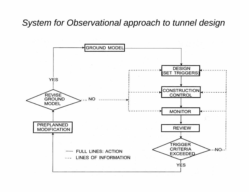
System for Observational approach to tunnel design

Eurocode 7 (EC7) includes the following remarks concerning an observational method.
Four requirements shall all be made before construction is started:Four requirements shall all be made before construction is started:
• The limits of behaviour, which are acceptable, shall be established.• The range of behaviour shall be assessed and it shall be shown that e a ge o be a ou
there is an acceptable probability that the actual behaviour will be within the acceptable limits.
• A plan of monitoring shall be devised which will reveal whether the actual behaviour lies within the acceptable limits The monitoring shallactual behaviour lies within the acceptable limits. The monitoring shall make this clear at a sufficient early stage; and with sufficiently short intervals to allow contingency actions to be undertaken successfully. The response time on the instruments and the procedures for analysing the results shall be sufficiently rapid in relationprocedures for analysing the results shall be sufficiently rapid in relation to the possible evolution of the system.
• A plan of contingency actions shall be devised which may be adopted if the monitoring reveals behaviour outside acceptable limits.D i t ti th it i h ll b i d tDuring construction the monitoring shall be carried out as planned and additional or replacement monitoring shall be undertaken if this becomes necessary. The results of the monitoring shall be assessed at appropriate stages and the
l d ti ti h ll b t i ti if thiplanned contingency actions shall be put in operation if this becomes necessary.

NATM – New Austrian Tunnelling Method
One of the most well known methods using some elements of an observational approach is the New Austrian Tunnelling Method, or NATM. The method, has often been mentioned as a ‘value engineered’ version of tunnelling due tovalue engineered version of tunnelling due to its use of light, informal support. It has long been understood that the ground, if allowed to deformunderstood that the ground, if allowed to deform slightly, is capable of contributing to its own support. NATM, with its use of modern means of monitoring and surface stabilisation, such as shotcrete and rock bolts, utilizes this effect
t ti llsystematically.

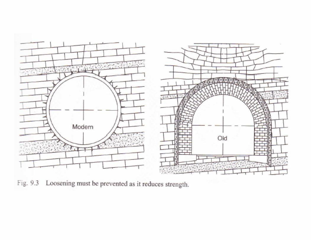
• Traditional tunnelling used first timber supports and l t t l h t i d t t bili t llater on steel arch supports in order to stabilise a tunnel temporarily until the final support was installed. The final support was masonry or a concrete arch. Rock loads d l d d di i i d d i ldeveloped due to disintegration and detrimental loosening of the surrounding rock and loosened rock exerted loads onto the support due to the weight of a
(loosened rock bulb (described by Komerell, Terzaghi and others). Detrimental loosening was caused by the available excavation techniques, the support means and the long period required to complete a tunnel section with many sequential intermediate construction stages. The result was very irregular heavy loading resulting in thick lining arches occupying a considerable percentage of the tunnel cross-section (in the early trans-Alpine tunnels the permanent structure may occupy as much as 40% of the excavated profile)

NATM: With a flexible primary support a new equilibrium shall be reached. This shall be controlled by in-situ deformation measurements After this new equilibrium isdeformation measurements. After this new equilibrium is reached an inner arch shall be built. In specific cases the inner arch can be omitted.
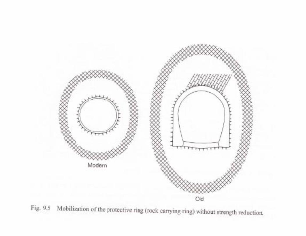
• The New Austrian Tunnelling Method constitutes a design where the surrounding rock- or soil formations of a tunnel are integrated into an overall ring like support structure. Thus the formations will th l b t f thi t t tthemselves be part of this support structure.
• With the excavation of a tunnel the primary stress field in the rock mass is changed into a more unfavourable secondary stress fieldmass is changed into a more unfavourable secondary stress field. Under the rock arch we understand those zones around a tunnel where most of the time dependent stress rearrangement processes takes place. This includes the plastic as well as the elastic behaving zonezone.
• Under the activation of a rock arch we understand our activities to maintain or to improve the carrying capacity of the rock mass, to
tili thi i it d t i fl f blutilise this carrying capacity and to influence a favourable development of the secondary stress field.
The main principles of NATM are:• The main load-bearing component of the tunnel is the surrounding rock
mass Support is ‘informal’ i e it consists of earth/rock-anchors andmass. Support is informal i.e. it consists of earth/rock-anchors and shotcrete, but support and final lining have confining function only.
• Maintain strength of the rock mass and avoid detrimental loosening by careful excavation and by immediate application of support and strengthening means Shotcrete and rock bolts applied close to thestrengthening means. Shotcrete and rock bolts applied close to the excavation face help to maintain the integrity of the rock mass.
• Rounded tunnel shape: avoid stress concentrations in corners where progressive failure mechanisms start.
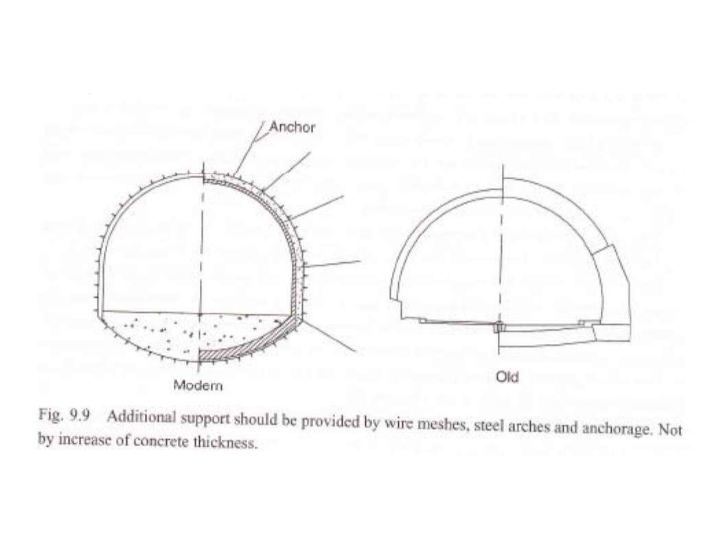
• Flexible thin lining: The primary support shall be thin-walled in order to minimise bending moments and to facilitate the stress rearrangement process without exposing the lining to unfavourable sectional forces. Additional support requirement shall not be added by increasing lining pp q y g gthickness but by bolting. The lining shall be in full contact with the exposed rock. Shotcrete fulfils this requirement.
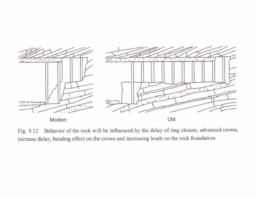
• Statically the tunnel is considered as a thick-walled tube consisting of the rock and lining The closing of the ring is therefore important i e thethe rock and lining. The closing of the ring is therefore important, i.e. the total periphery including the invert must be applied with shotcrete.
• In situ measurements: Observation of tunnel behaviour during construction is an integral part of NATM. With the monitoring and interpretation of deformations strains and stresses it is possible tointerpretation of deformations, strains and stresses it is possible to optimise working procedures and support requirements.


The concept of NATM is to control deformations and stress rearrangement process in order to obtain a required safety l l R i t diff d di thlevel. Requirements differ depending on the type of project in a subway project in built up areas stability and settlements may beup areas stability and settlements may be decisive, in other tunnels stability only may be observed. The NATM method isbe observed. The NATM method is universal, but particularly suitable for irregular shapes. It can therefore be applied g p ppfor underground transitions where a TBM tunnel must have another shape or di tdiameter.
Observations of tunnel behaviourO f f f• One of the most important factors in the successful application of observational methods like NATM is the observation of tunnel behaviour duringthe observation of tunnel behaviour during construction. Monitoring and interpretation of deformations, strains and stresses are important todeformations, strains and stresses are important to optimise working procedures and support requirements, which vary from one project to the other. In-situ observation is therefore essential, in order to keep the possible failures under control.
• Considerable information related to the use of instruments in monitoring soils and rocks are available from instrument manufacturersavailable from instrument manufacturers.
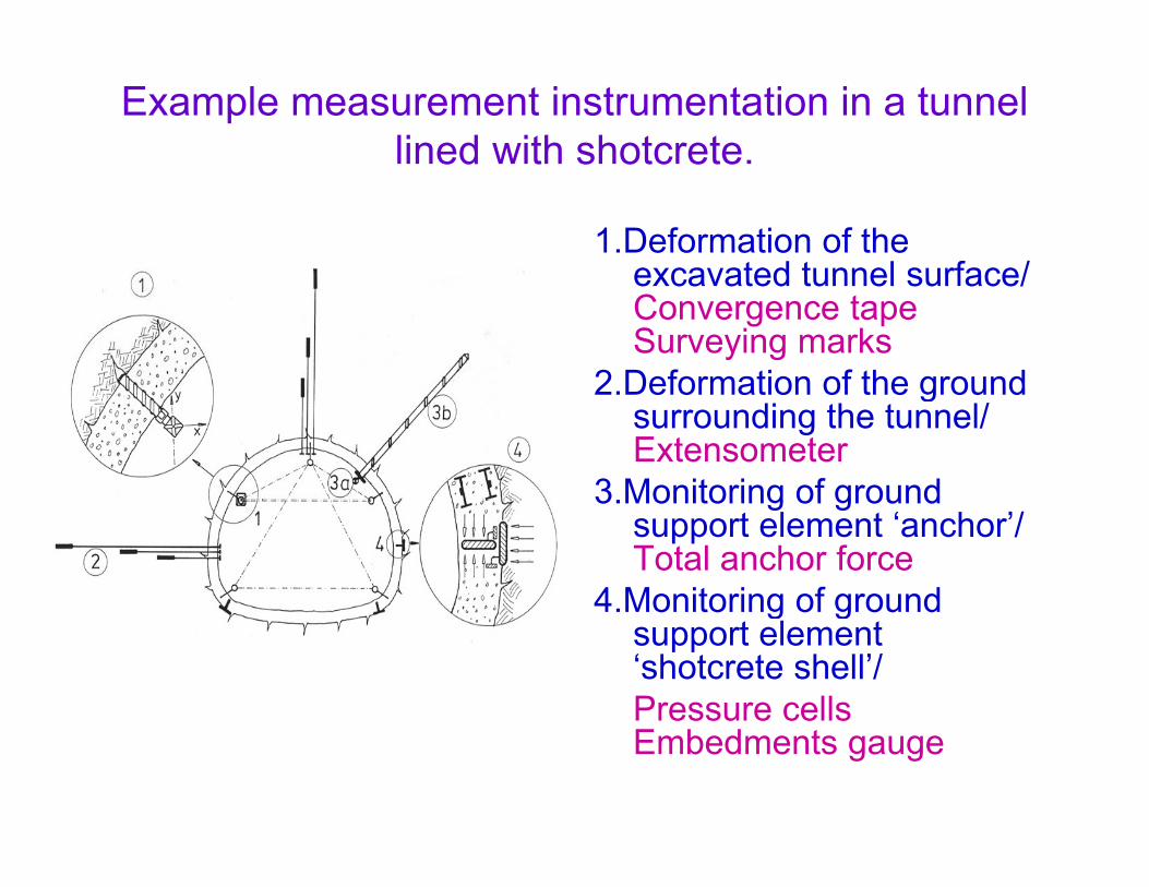
Example measurement instrumentation in a tunnel lined with shotcrete.ed t s otc ete
1.Deformation of the excavated tunnel surface/excavated tunnel surface/ Convergence tape Surveying marks
2 Deformation of the ground2.Deformation of the ground surrounding the tunnel/ Extensometer
3 Monitoring of ground3.Monitoring of ground support element ‘anchor’/ Total anchor force
4.Monitoring of ground4.Monitoring of ground support element ‘shotcrete shell’/Pressure cells Embedments gauge

NATM Process on site
• Cutting a length of tunnel here with a roadheader

Applying layer of shotcrete on reinforcement mesh

Primary lining applied to whole cavity, which remains under observationunder observation.

Final lining applied Running tunnels continuedFinal lining applied. Running tunnels continued.

Completed underground transition

Sketch of mechanical process and sequence of failure
around a cavity by stress rearrangement pressure
Main Pressure
Stage 1 Stage 2 Stage 3

Schematic representation of stresses around a circular
cavity with hydrostatic pressurecavity with hydrostatic pressure

• The Fenner-Pacher curve shows the relationshipshows the relationship between the deformation ΔR/R and required support resistance Pi. Simplistically, the more deformation is allowed, the less resistance is needed. In practice the supportIn practice, the support resistance reaches a minimum at a certain radial deformation, and support requirements increase if deformations become excessive.
• Fenner Pacher type• Fenner-Pacher-type diagrams can be generated to help evaluate the support methods best suited to the conditions.
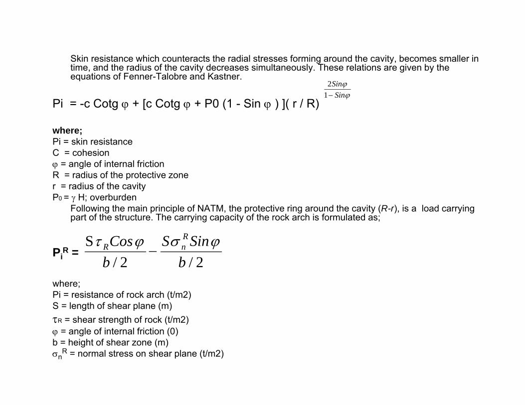
Skin resistance which counteracts the radial stresses forming around the cavity, becomes smaller in time, and the radius of the cavity decreases simultaneously. These relations are given by the equations of Fenner Talobre and Kastnerequations of Fenner-Talobre and Kastner.
Pi = -c Cotg ϕ + [c Cotg ϕ + P0 (1 - Sin ϕ ) ]( r / R)ϕϕ
SinSin−12
where;Pi = skin resistanceC = cohesionϕ = angle of internal frictionR = radius of the protective zoneR radius of the protective zone r = radius of the cavityP0 = γ H; overburden
Following the main principle of NATM, the protective ring around the cavity (R-r), is a load carrying part of the structure. The carrying capacity of the rock arch is formulated as;
PiR =
2/2/S
bSinS
bCos R
nR ϕσϕτ−
where;Pi = resistance of rock arch (t/m2)S = length of shear plane (m)τR = shear strength of rock (t/m2)ϕ = angle of internal friction (0)ϕ = angle of internal friction (0)b = height of shear zone (m)σn
R = normal stress on shear plane (t/m2)

ϕ, τR, σnR, can be measured in laboratories, where as S
b d i t d i d t lcan be measured in meters , on a drawing made to scale.

• Generally two separate supports are carried out. The first is a flexible outer arch or protective support designed to stabilize the structure accordingly. It consists of a
t ti ll h d k h ithsystematically anchored rock arch with surface protection, possibly reinforced by ribs and closed by an invertand closed by an invert.
• The behaviour of the protective support and the surrounding rock during the readjustmentthe surrounding rock during the readjustment process can be monitored by a measuring systemsystem.

The second means of support is an inner concrete arch, generally not carried out before the outer arch has reached equilibrium. In addition to
acting as a final functional lining (for installation of tunnel equipmentacting as a final, functional lining (for installation of tunnel equipment etc.) its aim is to establish or increase the safety factors as necessary.

• The resistance of the lining material (shotcrete) is:
)2/(sin bdP s
ss
t ατ
=
• An additional reinforcement (steel ribs etc ) gives
)2/(sin bα
An additional reinforcement (steel ribs, etc.) gives a resistance of:
FPstst
st τ
• where;
)2/(sin bP s
sti α
=
• where;
ssts
st E τττ 15== sEττ 15
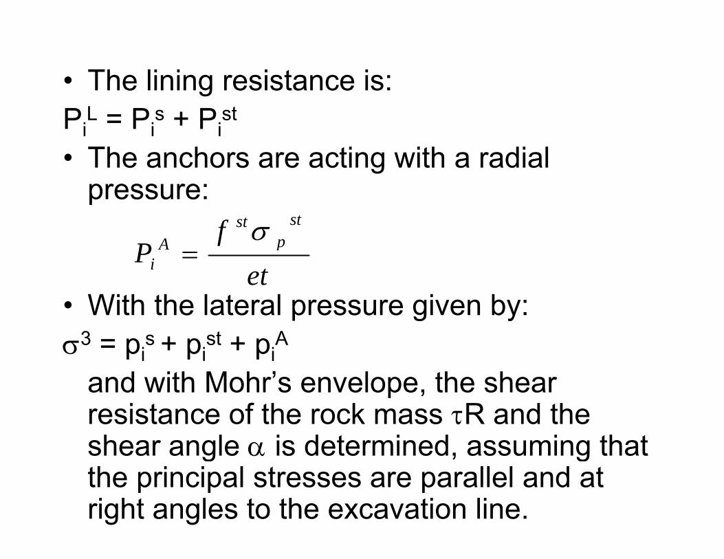
• The lining resistance is:Pi
L = Pis + Pi
st
• The anchors are acting with a radial pressure:
fP
stp
stA σ
• With the lateral pressure given by:et
fP pA
i =
With the lateral pressure given by:σ3 = pi
s + pist + pi
A
and with Mohr’s envelope the shearand with Mohr s envelope, the shear resistance of the rock mass τR and the shear angle α is determined, assuming that g α , gthe principal stresses are parallel and at right angles to the excavation line.

The carrying capacity of the rock arch is i bgiven by:
sincos SS RR ϕσϕτ ⋅⋅2/sin
2/cos
bS
bSP nR
iϕσϕτ ⋅
−⋅
=
The resistance of the anchors against the movement of the shear body towards themovement of the shear body towards the cavity is:
)2/(cos
baf
Pst
pst
Ai
βσ⋅=
)2/(beti

• The total carrying capacity of the outer arch is then:
miniA
iR
iL
iw
i PPPPP ≥++=
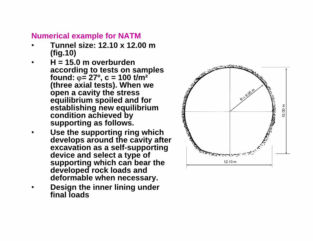
Numerical example for NATM• Tunnel size: 12 10 x 12 00 m• Tunnel size: 12.10 x 12.00 m
(fig.10)• H = 15.0 m overburden
according to tests on samples f d 27º 100 t/ ²found: ϕ= 27º, c = 100 t/m² (three axial tests). When we open a cavity the stress equilibrium spoiled and for
t bli hi ilib iestablishing new equilibrium condition achieved by supporting as follows.
• Use the supporting ring which pp g gdevelops around the cavity after excavation as a self-supporting device and select a type of supporting which can bear the pp gdeveloped rock loads and deformable when necessary.
• Design the inner lining under final loadsfinal loads

The (1) supporting system is capable of carrying safely the loads, the (2) lining is for safety and to bear the additional , ( ) g yloads which are probable to develop after the supports are installed.
S ti ill i t i thi lSupporting will consists in this example:a: Shotcrete (15+10) cm in layers by two shotsb: Bolts spaced 2 00 x 2 00 m in rings with diameter Ø 26 mmb: Bolts spaced 2.00 x 2.00 m in rings with diameter Ø 26 mm.c: Rib steel channel supports (2 x 14)d: by ground supporting ringy g pp g gTo find the radius of disturbed zone R:Talobre formula:
[ ] ϕϕ
ϕϕϕ sin1sin2
0 )()sin1(cotcot −⋅−⋅+⋅+⋅−=RrPgcgcPi R
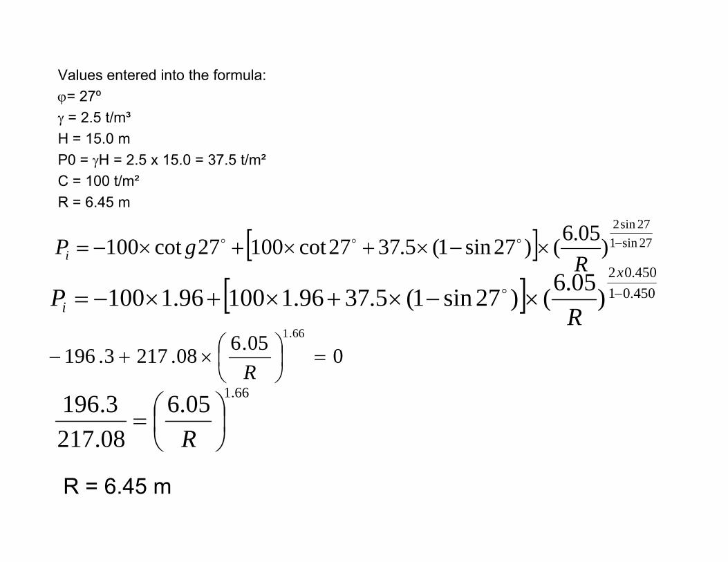
Values entered into the formula:ϕ= 27ºϕγ = 2.5 t/m³H = 15.0 mP0 = γH = 2.5 x 15.0 = 37.5 t/m²C = 100 t/m²R = 6.45 m
[ ] 27sin127sin2
)05.6()27sin1(53727cot10027cot100 −××+×+× gP ooo [ ] 27sin1)()27sin1(5.3727cot10027cot100 ×−×+×+×−=R
gPi
[ ] 450.01450.02
)05.6()27sin1(5.3796.110096.1100 −×−×+×+×−=x
i RP o
R005.608.2173.196
66.1
=⎟⎠⎞
⎜⎝⎛×+−
R661 66.105.6
08.2173.196
⎟⎠⎞
⎜⎝⎛=
R
R = 6.45 m

Shotcrete:d = 25 cmd = 25 cm σc
28 = 160 kg/cm² compressive strength shear in concrete (assume 20% of σc28)
th it i l dthe capacity carrying loadτs
h = 0.20 · 160 = 32 kg/cm² = 320 t/m²d = thickness of shotcrete in (cm)α = π/4 - ϕ/2 angle of shear plane with vertical b = shear failure height of the cavity (see Fig.10)sin 31 5 = 0 520;sin 31.5 0.520; b/2= r cos α= 6.05xcos31.5=5.15
320250 2/9.2915.552.0
32025.0 mtpci =
⋅⋅
=
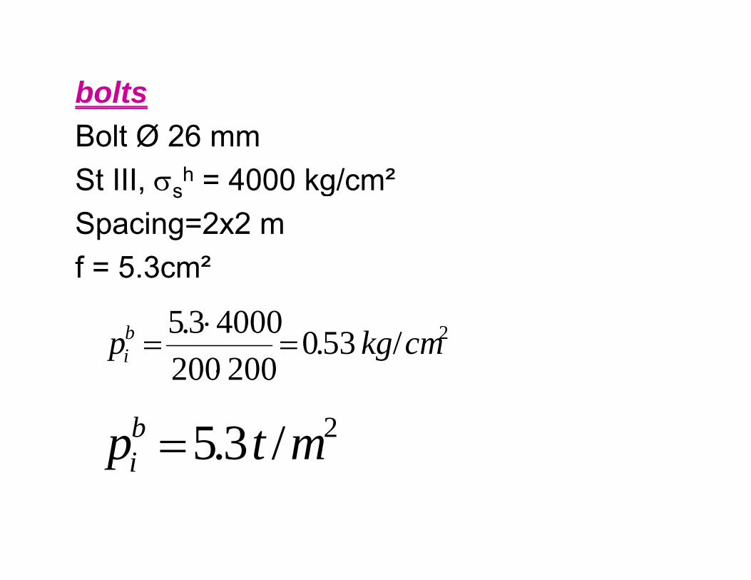
boltsBolt Ø 26 mmSt III σ h = 4000 kg/cm²St III, σs
h = 4000 kg/cmSpacing=2x2 mf = 5.3cm²
2400035b ⋅ 2/53.0200200
40003.5 cmkgpbi =
⋅=
2/3.5 mtpbi =

steel ribst = spacing 2.00 m
τN = normal stress = 142 t/m²
read on Xt spacing 2.00 mF = 2 · 20.4 cm² = 40.8 cm² =
0.00408 m²τst = τc · 15 = 320 · 15 = 4800 t/m²
read on XτZ = minor stress = 37.2 t/m²
τR = shear stress = 170 t/m² read on Y
²/56.3600.215.552.0
480000408.0
sin
·mt
tbF
P ststi =
⋅⋅⋅
==α
τ
2sin t⋅⋅α
Connect AB and find the centre (W) draw the circle. Tangent at the point B (BB’) soOB’ C h i 100 t/ ²OB’ = Cohesion = 100 t/m²ϕ = internal friction angle (27º) R calculated (Talobre formula) as 6.45 m. Width of the protective ring 6.45-6.05 = 0.4m drawn through A, B
d th i t ti bi ti ith th iddl i (C)and the intersection bisecting with the middle ring (C); ABC shear failure line drawn and thus (S) measured.Bolt length l = 4.00 m is taken and inclination βmeasuredΣP c + b + st 29 9 + 5 3 + 36 56 70 26 t/ ²ΣPi = pi
c + pib + pi
st = 29.9 + 5.3 + 36.56 = 70.26 t/m²

bearing capacity of the supporting ring
Sin ϕ = sin 27 = 0 450Sin ϕ = sin 27 = 0.450Cos ϕ = cos 27 = 0.891
thusS = 4.54 m (from figure 17)ϕ = 27ºb/2 = 5.15 mτR = 170 t/m²τN = 142 t/m² enter the formula
15.5450.01426.4
15.5891.01706.4 ⋅⋅
−⋅⋅
=RCp
2/22.78 mtp RC =
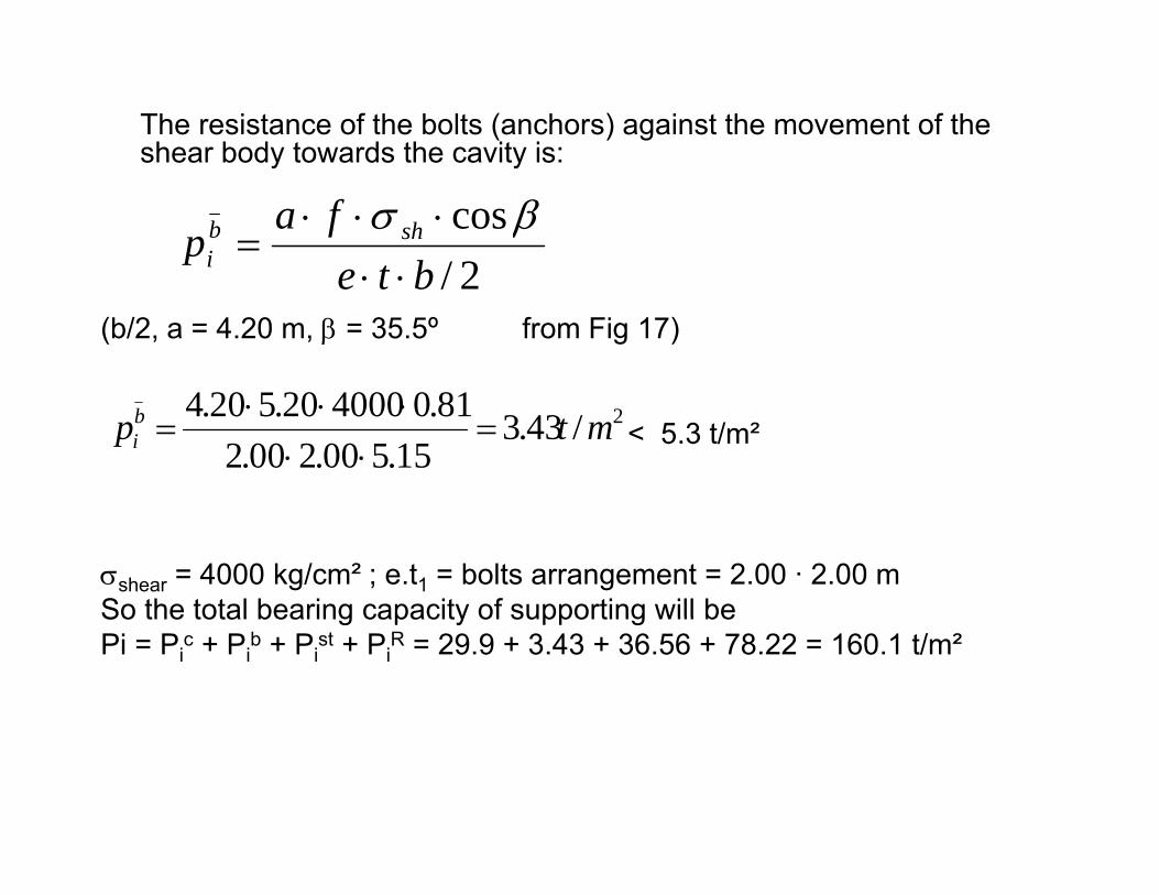
The resistance of the bolts (anchors) against the movement of the shear body towards the cavity is:y y
2/cos
btefa
p shbi ⋅⋅
⋅⋅⋅=
βσ
(b/2, a = 4.20 m, β = 35.5º from Fig 17)
2/bte ⋅⋅
< 5.3 t/m²2/43.3
15.500.200.281.0400020.520.4 mtpb
i =⋅⋅
⋅⋅⋅=
σshear = 4000 kg/cm² ; e.t1 = bolts arrangement = 2.00 · 2.00 mSo the total bearing capacity of supporting will beSo the total bearing capacity of supporting will bePi = Pi
c + Pib + Pi
st + PiR = 29.9 + 3.43 + 36.56 + 78.22 = 160.1 t/m²


![Ademoladij-[eCommerce Website for Your Comapny by SARV]](https://static.documents.pub/doc/80x56/577d20be1a28ab4e1e93a8b8/ademoladij-ecommerce-website-for-your-comapny-by-sarv.jpg)


