User's Guide Solvent Ink Color Inkjet Printer IP-6600 Seiko I Infotech Inc. Read this User's Guide to use the printer safely and properly. Keep this manual in a place where you can quickly access it at any time. U00086051201
Transcript
User's Guide
Solvent InkColor Inkjet Printer
IP-6600
Seiko I Infotech Inc.
Read this User's Guide to use the printer safely and
properly. Keep this manual in a place where you
can quickly access it at any time.
U00086051201
MJAN
Text Box
Océ CS 6060
IP-6600 Solvent Ink Color Inkjet Printer User's GuideDocuments Number U00086051201
First Edition, December 2003Second Edition, February 2004
Seiko I Infotech Inc. reserves the right to make changes without notice to the specifications andmaterials contained herein and shall not be responsible for any damages (includingconsequential) caused by reliance on the materials presented, including but not limited to typo-graphical, arithmetic, or listing errors.
Please address any questions, comments, and suggestions to:
Seiko I Infotech Inc.Blue Sphere Nihonbashi Bldg.11-1, Nihonbashi Tomizawa-cho,Chuo-ku, Tokyo 103-0006, Japan
This manual acknowledges the following trademarks:
SII is a trademark of Seiko I Infotech Inc.All other trademarks are the properties of their respective companies.
This equipment has been tested and found to comply with the limits for a Class A digital device,
pursuant to Part 15 of the FCC Rules. These limits are designed to provide reasonable protection
against harmful interference when the equipment is operated in a commercial environment.
This equipment generates, uses, and can radiate radio frequency energy and, if not installed and
used in accordance with the instruction manual, may cause harmful interference to radio
communications. Operation of this equipment in a residential area is likely to cause harmful
interference in which case the user will be required to correct the interference at his own expense.
Durch die Kennzeichnung dieses Produktes mit dem CE-Zeichen erklärt Seiko den folgenden
Direktiven der Europäischen Union zu entsprechen (mit Wirkung vom siehe Datum):
Januar 1996:- EG-Direktive 73/23/EEC ergänzt durch EG-Direktive 93/68/EEC, Angleichung der
Gesetze der einzelnen Mitgliedsstaaten bezüglich Geräten mit niedriger Betriebsspannung.
Januar 1996:- EG-Direktive 89/336/EEC, Angleichung der Gesetze der einzelnen Mitgliedsstaaten
bezüglich elektromagnetischer Kompatibilität.
Den vollständigen Text dieser Erklärung einschließlich der Definition der entsprechenden
Direktiven sowie der jeweiligen Standards erhalten Sie von Ihrem Seiko Colorgrafx Systems
Kundendienst oder Ihrem Seiko Engineering Systems Kundendienst.
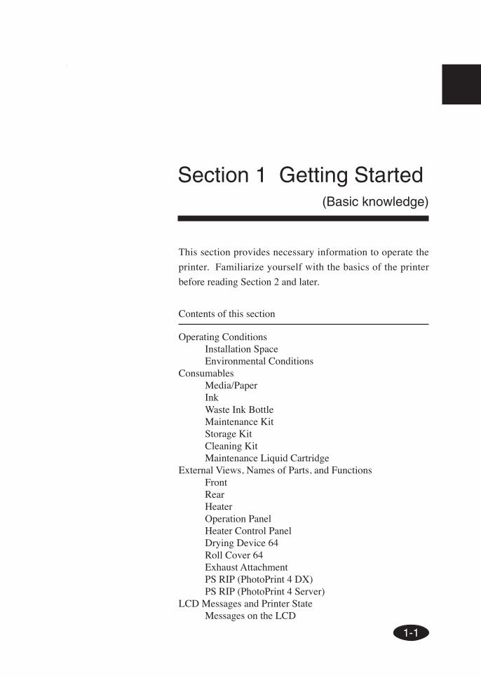
Thank you very much for purchasing the IP-6600 Color Inkjet
Printer (simply called the printer below).
This printer is a color inkjet printer that adopts solvent ink, supports
64 inch media width, and builts-in SCSI interface.
This manual, the IP-6600 User's Guide, describes the features of
the printer, names of components, information to be known before
use, and basic operations, such as how to turn the power on and off
and set media and ink.
The following items should be read before reading Section 1.
- Deliverables
- Safety precautions
- Handling precautions
- Manual legend (notation rules)
Read these items to use the printer safely and properly. Keep this
manual in a place where you can quickly access it at any time.
Introduction
i
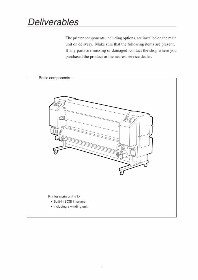
Deliverables
The printer components, including options, are installed on the main
unit on delivery. Make sure that the following items are present.
If any parts are missing or damaged, contact the shop where you
purchased the product or the nearest service dealer.
Printer main unit <1>
• Built-in SCSI interface.
• Including a winding unit.
Basic components
ii
Power cord
<2>
• Power cord for printer
• Power cord for heater
Roll paper(for installations)
<1>
User's Guide
<1 copy>Waste ink bottle IP6-109
<1>Paper tube 64"
<1>
Maintenance kit IP6-108
<1 set>
• Cap cleaning liquid: 100 ml
• Wiper cleaning liquid: 100 ml
• Cleaning swab: 50 pieces
• Syringe: 10 pieces
Ink kit 6 colors IP6-100
(Y, M, C, Bk, Lc, Lm)
<1>
SCSI cable
<1>
Accessories
+ screw driver
(for head up/down adjustment)
*: Ink capacity of each ink cartridge for ink kit 6 colors IP6-100 is 500 ml.Approximately 100 ml ink for each color is consumed at initial ink charge. Therefore, this 100 ml ink for eachcolor cannot be used for print.
iii
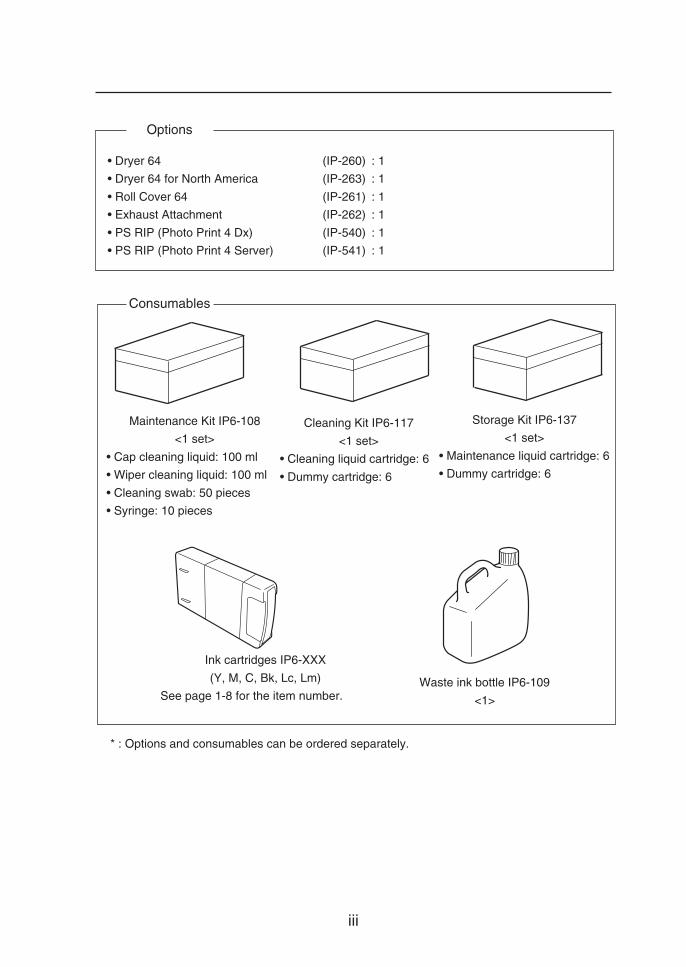
Waste ink bottle IP6-109
<1>
* : Options and consumables can be ordered separately.
Maintenance Kit IP6-108
<1 set>
• Cap cleaning liquid: 100 ml
• Wiper cleaning liquid: 100 ml
• Cleaning swab: 50 pieces
• Syringe: 10 pieces
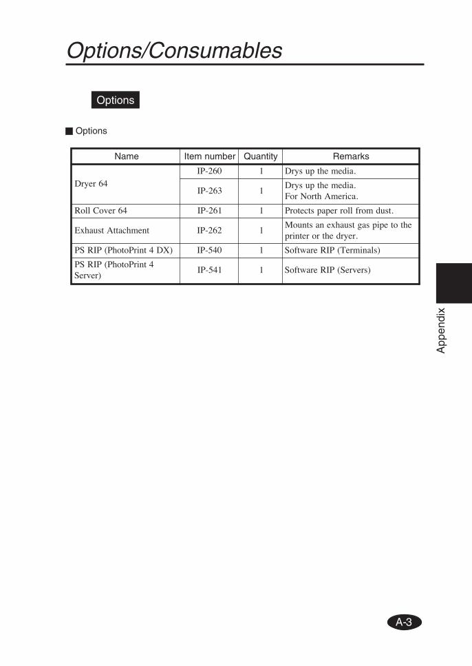
Options
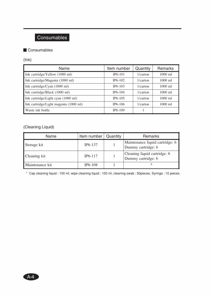
Consumables
• Dryer 64 (IP-260) : 1
• Dryer 64 for North America (IP-263) : 1
• Roll Cover 64 (IP-261) : 1
• Exhaust Attachment (IP-262) : 1
• PS RIP (Photo Print 4 Dx) (IP-540) : 1
• PS RIP (Photo Print 4 Server) (IP-541) : 1
Storage Kit IP6-137
<1 set>
• Maintenance liquid cartridge: 6
• Dummy cartridge: 6
Cleaning Kit IP6-117
<1 set>
• Cleaning liquid cartridge: 6
• Dummy cartridge: 6
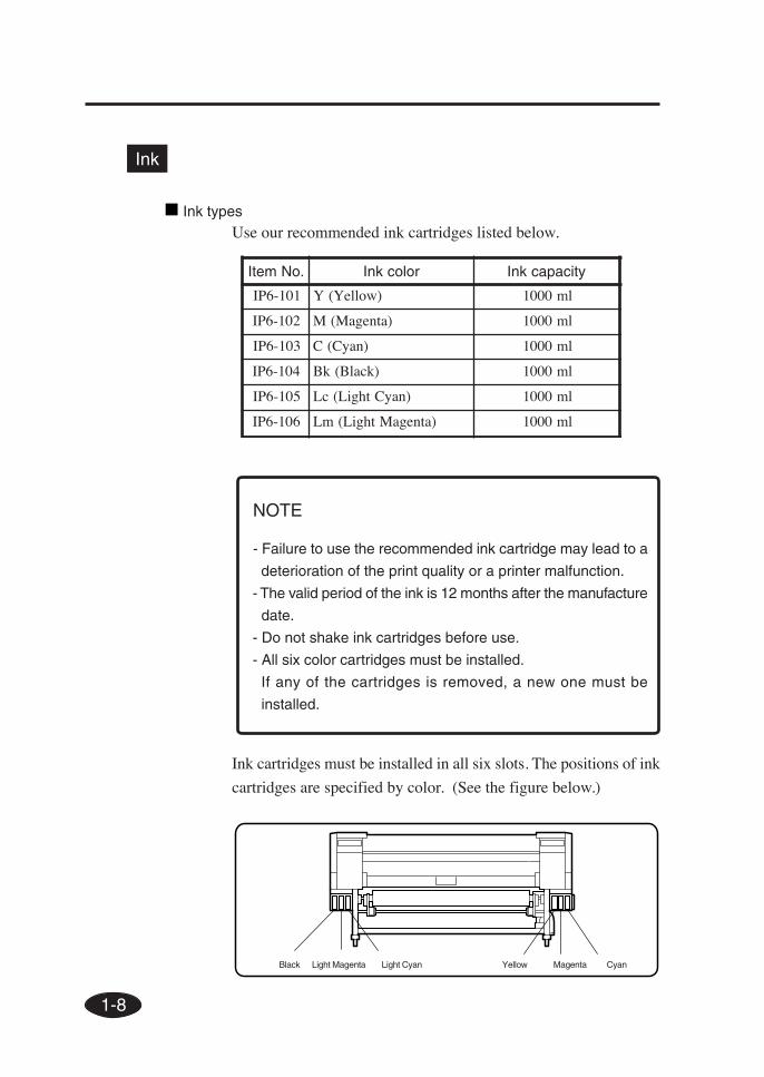
Ink cartridges IP6-XXX
(Y, M, C, Bk, Lc, Lm)
See page 1-8 for the item number.
iv
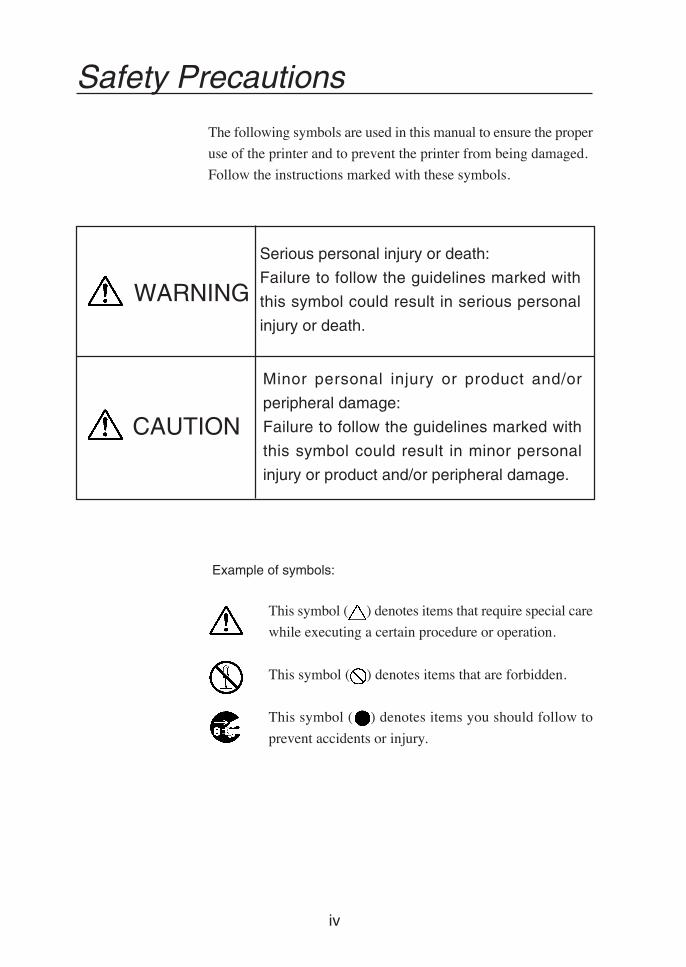
Example of symbols:
This symbol ( ) denotes items that require special care
while executing a certain procedure or operation.
This symbol ( ) denotes items that are forbidden.
This symbol ( ) denotes items you should follow to
prevent accidents or injury.
Safety Precautions
The following symbols are used in this manual to ensure the proper
use of the printer and to prevent the printer from being damaged.
Follow the instructions marked with these symbols.
Minor personal injury or product and/or
peripheral damage:
Failure to follow the guidelines marked with
this symbol could result in minor personal
injury or product and/or peripheral damage.
Serious personal injury or death:
Failure to follow the guidelines marked with
this symbol could result in serious personal
injury or death.
WARNING
CAUTION
v
Use the power supply voltage specified on the nameplate. DO NOT
plug several devices into one electrical outlet as this might result in fire
or electric shock.
Make sure the printer is well grounded. If not, a short circuit may cause
fire or electrical shock.
DO NOT disassemble or remodel the printer. DO NOT repair the printer
by yourself. Doing so may cause fire, electric shock or other accidents.
DO NOT damage, break, process, or heat the power cable. If it is
damaged, replace it with a new one. Using a damaged power cable may
cause fire or electric shock.
NEVER use the printer in a place of extreme humidity or any place
where it can possibly be splashed by any liquids. If any liquids get into
the printer, it could lead to fire, electric shock, or other serious accidents.
DO NOT remove the covers attached to the printer because they contain
high-voltage and extremely hot parts. Careless removal might result in
an electric shock or burn.
DO NOT allow metal or liquids to touch the internal parts of the printer.
Doing so may cause fire, electric shock, or other accidents.
DO NOT disconnect or connect the power cable with wet hands. Doing
so may lead to electric shock.
Turn the printer off and unplug the power cable immediately after it
thundered.
WARNING
vi
Power OFF the printer and unplug the power cable from the power outlet
in any of the following cases:
• When putting your hands inside the printer.
• Smoke, strange noise or smells generate from the printer.
• A piece of metal or any liquid touches the internal parts or slot of
the printer.
• An error requiring service by a service center occurs.
DO NOT put your hand into the paper delivery slot as it may lead to
injury by the cutting device.
Do not leave the printer stained with ink.
The coating of the printer may be damaged.
The ink used for the device contains organic solvent
(Ethylenglycolmonbutyleteracetat).
Therefore, observe the local rules strictly related to organic solvent stuff.
The ink used for the device contains organic solvent
(Ethylenglycolmonobutyletheracetat), Since the ink is flammable, never
use fire when using the device.
Do not swallow ink or avoid its splashes on the eye. If it gets into the
eye, wash it off with a clean running water and consult a doctor as
required. If it is swallowed, do not try to vomit it forcefully, but cunsult
a doctor.
Keep ink cartridges out of reach of children.
WARNING
vii
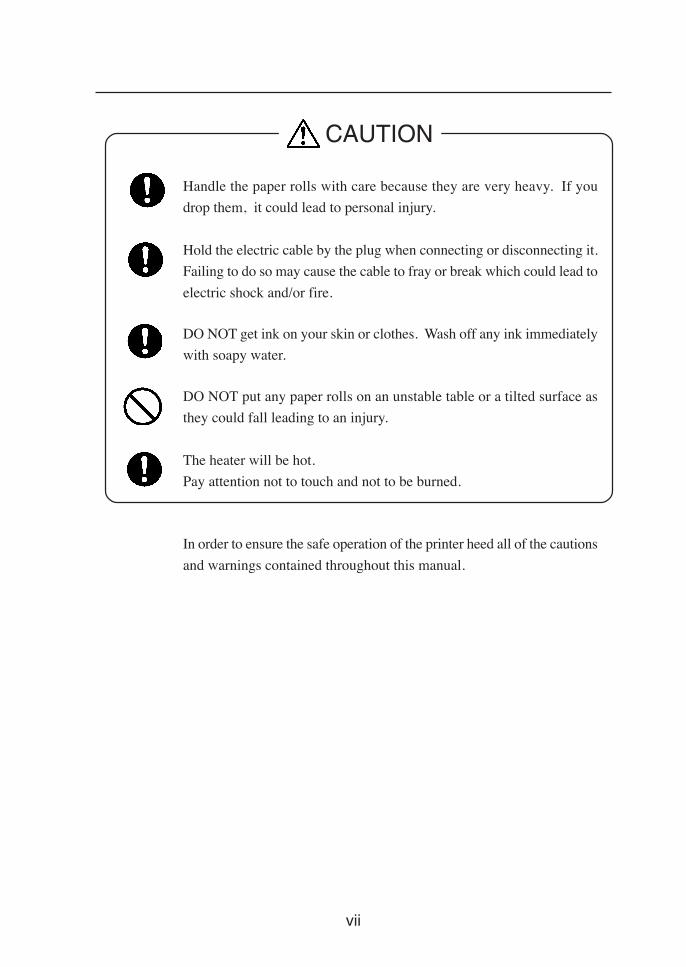
Handle the paper rolls with care because they are very heavy. If you
drop them, it could lead to personal injury.
Hold the electric cable by the plug when connecting or disconnecting it.
Failing to do so may cause the cable to fray or break which could lead to
electric shock and/or fire.
DO NOT get ink on your skin or clothes. Wash off any ink immediately
with soapy water.
DO NOT put any paper rolls on an unstable table or a tilted surface as
they could fall leading to an injury.
The heater will be hot.
Pay attention not to touch and not to be burned.
In order to ensure the safe operation of the printer heed all of the cautions
and warnings contained throughout this manual.
CAUTION
viii
Handling Precautions
Power Supply
1. Install the printer near an easily accessible electrical outlet.2. Do not provide power to the printer through the same power
line as for noise-generating devices, such as a motor.3. Use the power supply matched with the specification of the
printer.4. Connect the power cable to an electrical outlet. Do not plug
several devices into one electrical outlet.
Printer
1. Do not place anything on top of the printer. Do not rest yourelbows on the printer.
2. Open and close the top cover gently from the front of the printerwith both hands.
3. Before connecting or disconnecting the interface connector, turnthe printer off.
4. Do not clean the surface of the cover with benzene or paintthinner. The coating may come off or deteriorate.Wipe the cover clean with a soft cloth. If the cover is very dirty,use a cloth moistened with a neutral detergent.
5. Do not touch the ink-jet head surface.
Regular Inspection and Maintenance
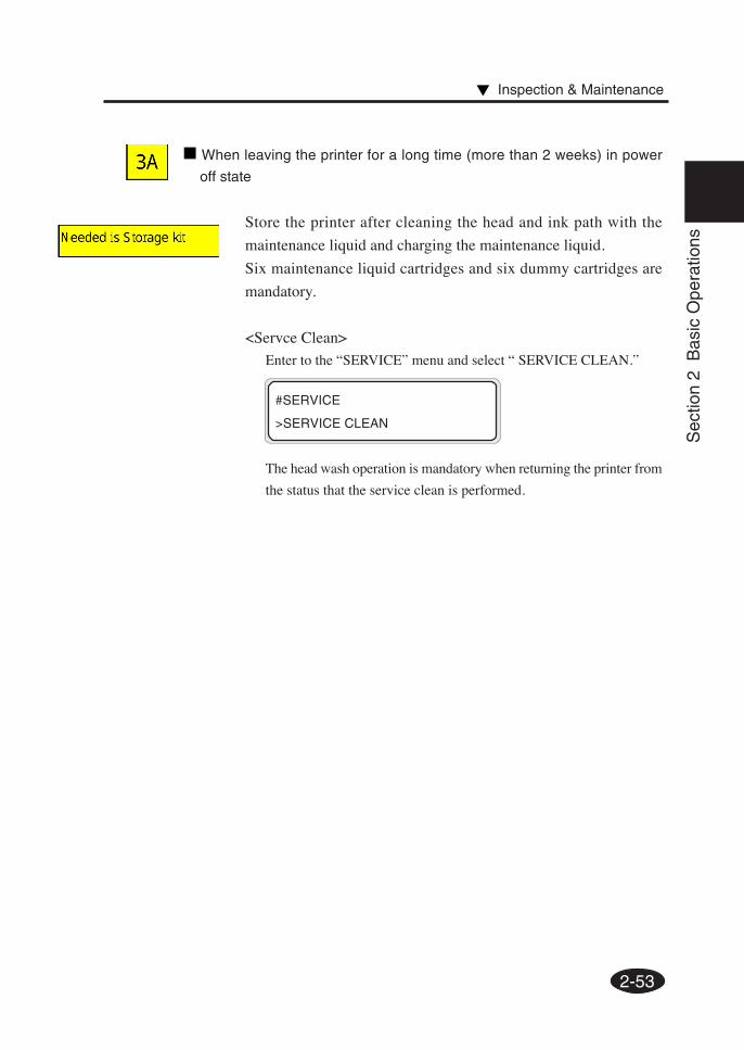
The following regular inspection and maintenance must beperformed in terms of characteristics of solvent ink.1. Clean the capping unit every day.2. Check moisture of wipper sponge every day.3. Perform the head cleaning every one month.4. Perform the service cleaning when leaving the printer for long
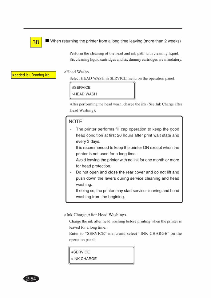
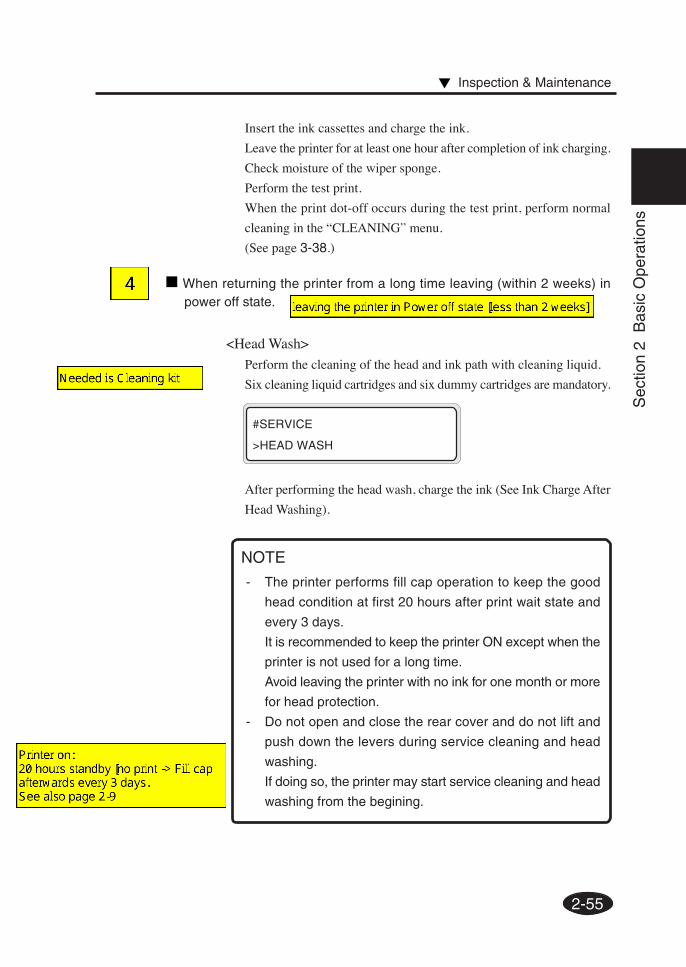
time (2 weeks or more at power off state.)5. Perform the head wash and the ink charge before printing when
leaving the priner for long time.
See pages 2-48 and 2-59 for regular inspection and maintenance.
ix
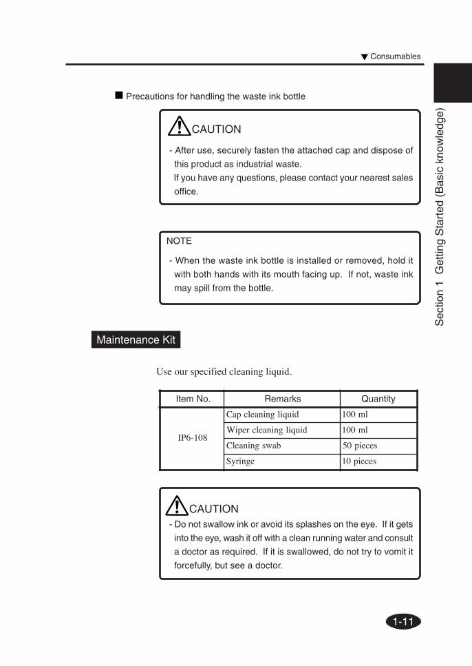
Consumables
1. Always use the recommended consumables (media, ink, etc.).
Failure to follow this instruction may cause poor print quality
or a breakdown.
2. Do not use ink past the date of expiration as this may cause a
breakdown.
3. Put a used ink cartridge into a plastic bag and dispose of it as an
industrial waste. Observe any regulations for disposal of waste
ink bottles.
4. Do not get ink on your skin or clothes. Wash off any ink
immediately with soapy water.
5. Check waste ink bottle regularly so as not to leak the waste ink.
6. When the waste ink bottle is installed or removed, spread the
stain preventing sheet so as not to stain the floor with spilt ink.
7. Store ink in a dark and cool place.
NEVER store ink in a high temperature or direct sunshining
place.
Doing so, ink may cause characteristic changes.
8. Do not attempt to disassemble ink cantridges.
9. Media for solvent ink on the market can be used for this printer.
x
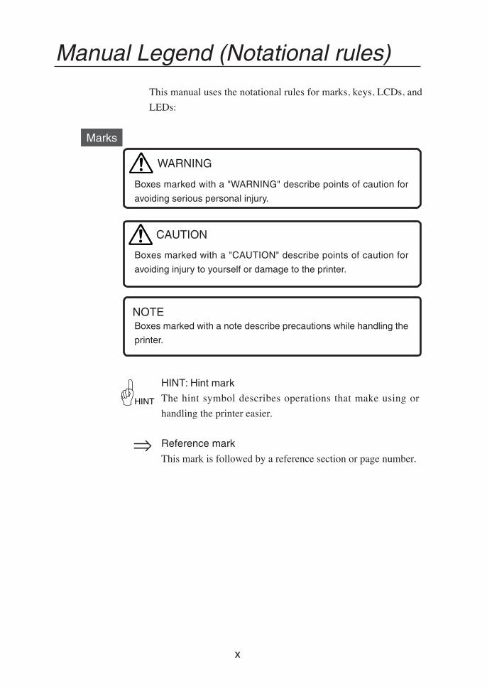
Marks
Boxes marked with a "WARNING" describe points of caution for
avoiding serious personal injury.
Boxes marked with a "CAUTION" describe points of caution for
avoiding injury to yourself or damage to the printer.
Boxes marked with a note describe precautions while handling the
printer.
HINT: Hint mark
The hint symbol describes operations that make using or
handling the printer easier.
Reference mark
This mark is followed by a reference section or page number.
Manual Legend (Notational rules)
This manual uses the notational rules for marks, keys, LCDs, and
LEDs:
NOTE
HINT
WARNING
CAUTION
xi
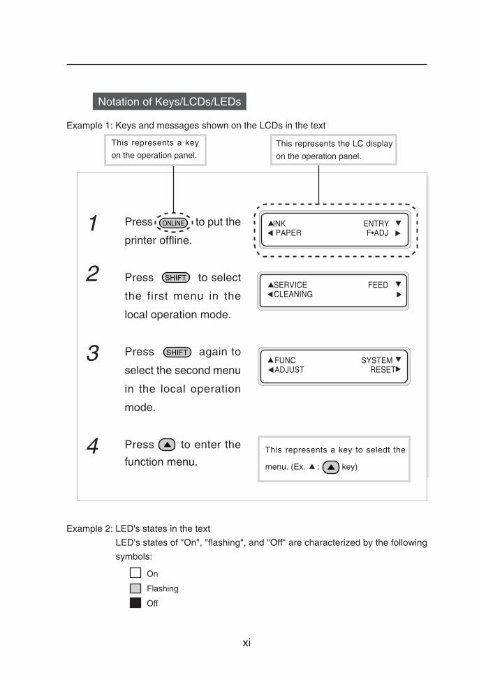
1 Press to put the
printer offline.
2 Press to select
the first menu in the
local operation mode.
3 Press again to
select the second menu
in the local operation
mode.
4 Press to enter the
function menu.
This represents a key
on the operation panel.This represents the LC display
on the operation panel.
On
Flashing
Off
Example 2: LED's states in the text
LED's states of "On", "flashing", and "Off" are characterized by the following
symbols:
Example 1: Keys and messages shown on the LCDs in the text
INK ENTRY PAPER F•ADJ
SERVICE FEED CLEANING
FUNC SYSTEM ADJUST RESET
This represents a key to seledt the
menu. (Ex. : key)
Notation of Keys/LCDs/LEDs
xii
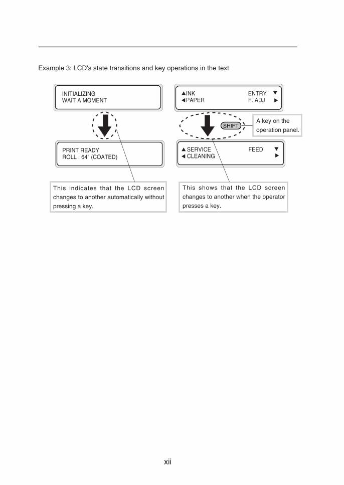
PRINT READYROLL : 64" (COATED)
INK ENTRY PAPER F. ADJ
Example 3: LCD's state transitions and key operations in the text
A key on the
operation panel.
This indicates that the LCD screen
changes to another automatically without
pressing a key.
This shows that the LCD screen
changes to another when the operator
presses a key.
INITIALIZINGWAIT A MOMENT
SERVICE FEED CLEANING
CONTENTS-1
TABLE OF CONTENTS
Introduction
Deliverables ......................................................................................... i
Safety Precautions.............................................................................. iv
Handling Precautions........................................................................ viii
Manual Legend (Notational rules) ....................................................... x
PUTNORF yek .retaehtnorfehtrofeulavgnittesehtsesaercnI
NWODTNORF yek .retaehtnorfehtrofeulavgnittesehtsesaerceD
FFO/NOTNIRP yek .retaehtnirpehtffo/nosnruT
PUTNIRP yek .retaehtnirpehtrofeulavgnittesehtsesaercnI
NWODTNIRP yek .retaehtnirpehtrofeulavgnittesehtsesaerceD
FFO/NORAER yek .retaehraerehtffo/nosnruT
PURAER yek .retaehraerehtrofeulavgnittesehtsesaercnI
NWODRAER yek .retaehraerehtrofeulavgnittesehtsesaerceD
1-19
Sec
tion
1 G
ettin
g S
tart
ed (
Bas
ic k
now
ledg
e)
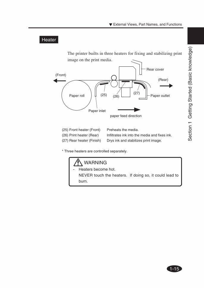
Dryer 64 (Option)
The dryer 64 dries the output media.
Roll Cover 64 (Option)
Protects paper roll from dust.
Exhaust Attachment (Option)
Mounts an exhaust gas pipe to the printer or the drying device.
PS RIP (PhotoPrint 4 DX) (Option)
RIP software for the IP-6600.
PS RIP (PhotoPrint 4 Server) (Option)
RIP software for the IP-6600.
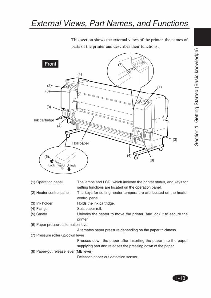
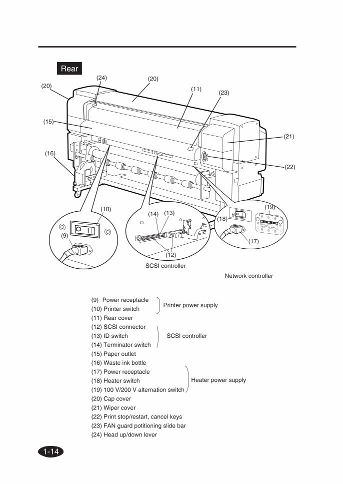
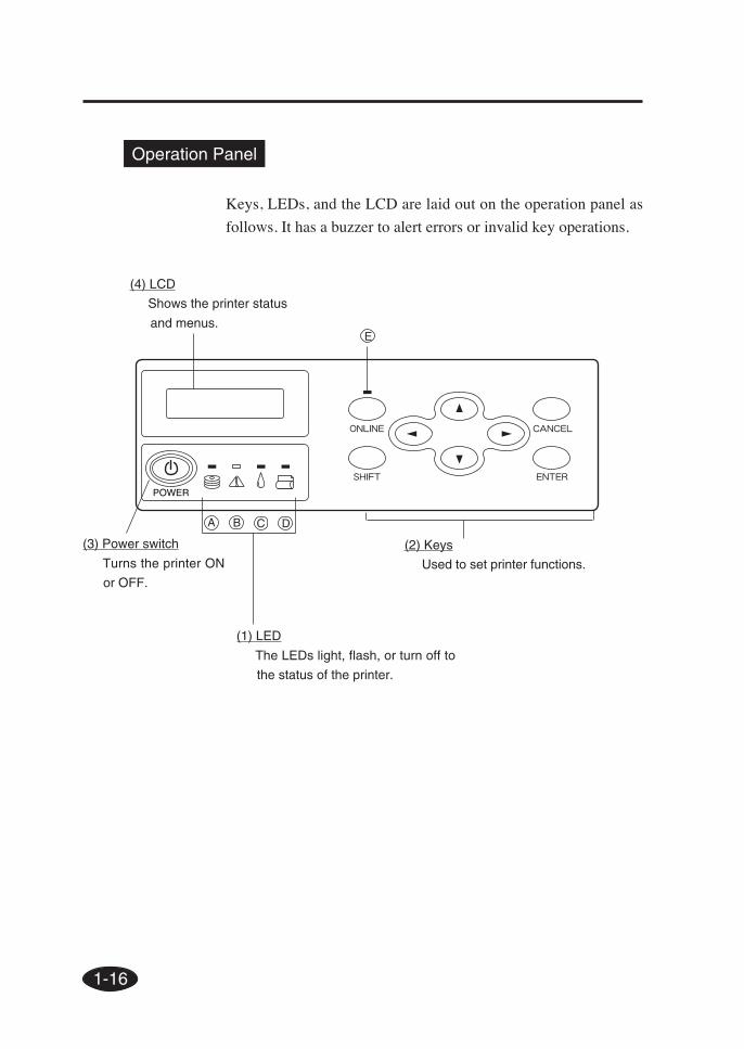
External Views, Part Names, and Functions
1-20
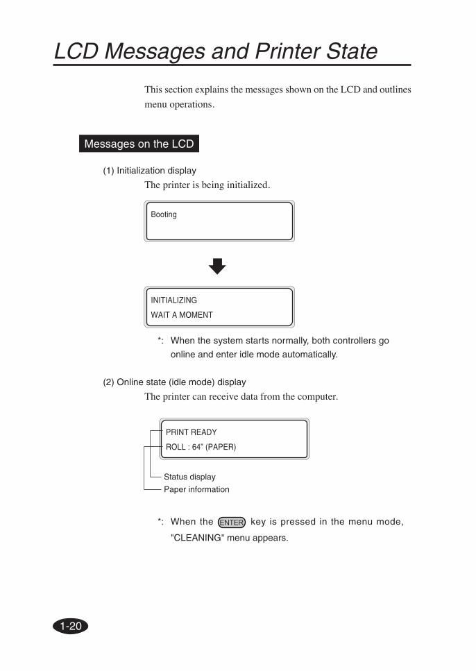
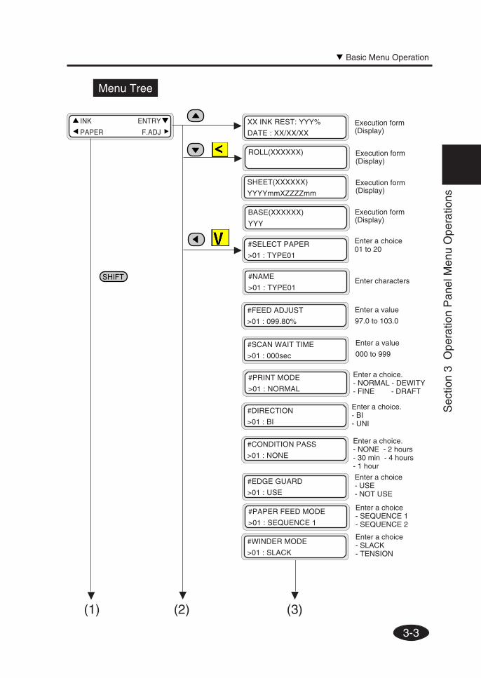
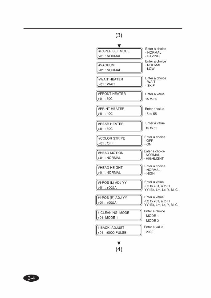
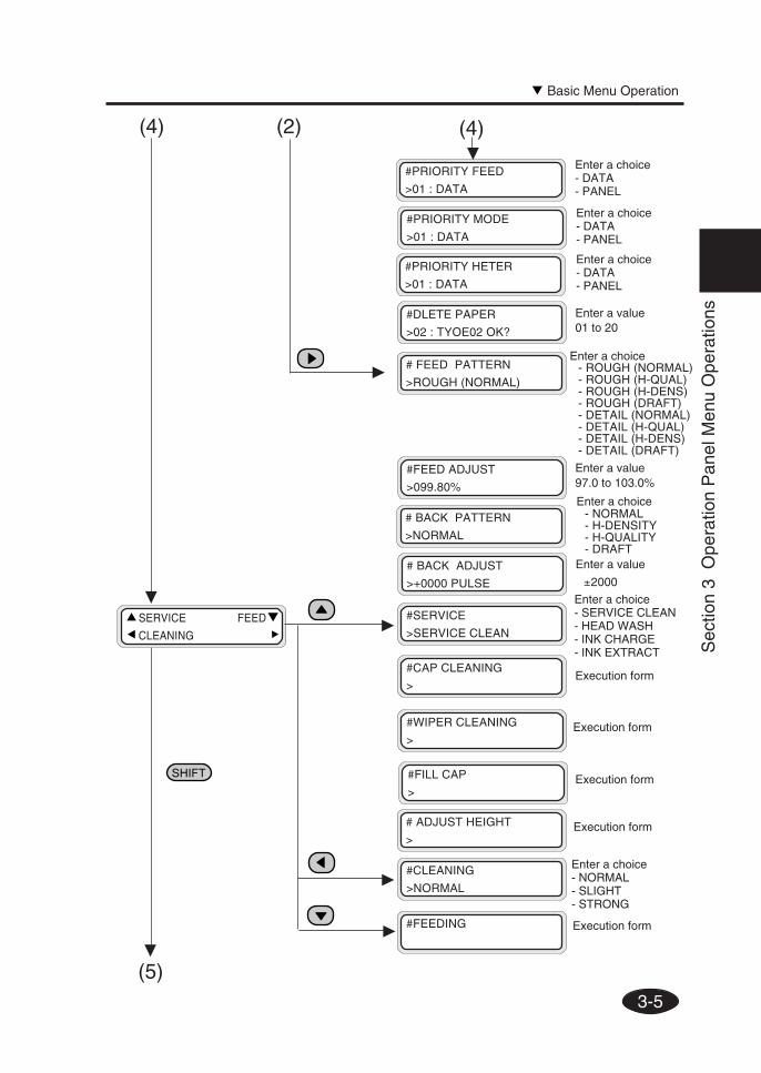
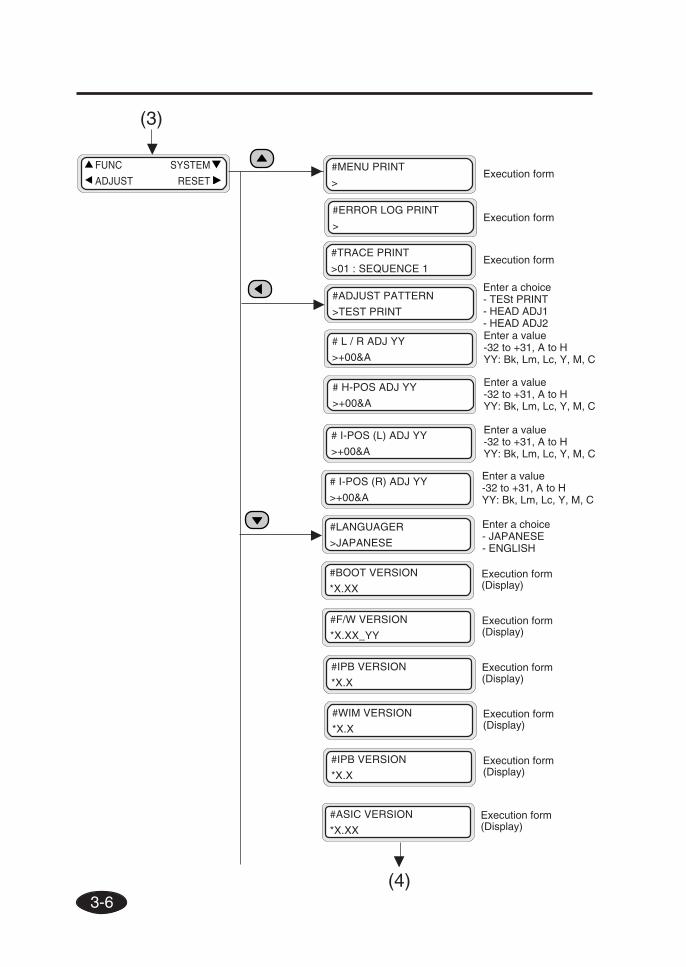
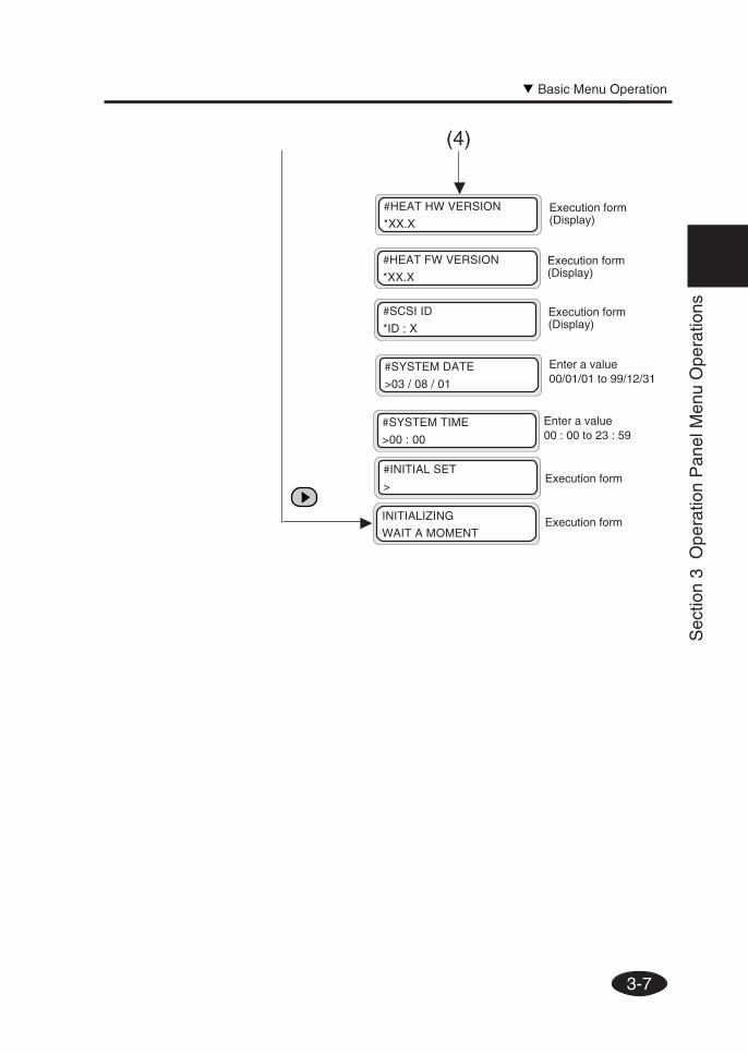
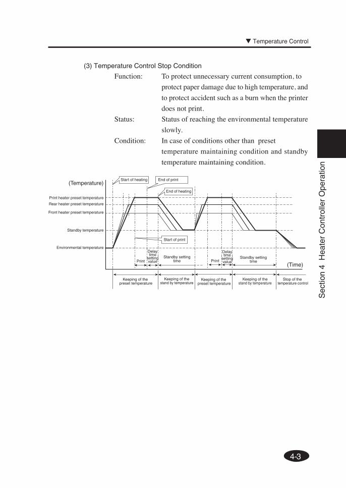
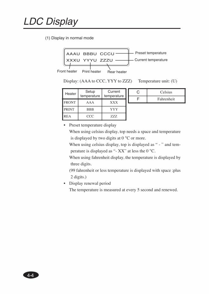
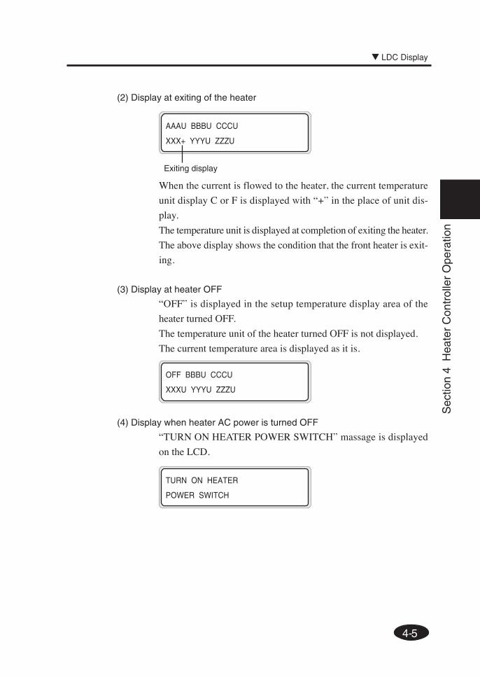
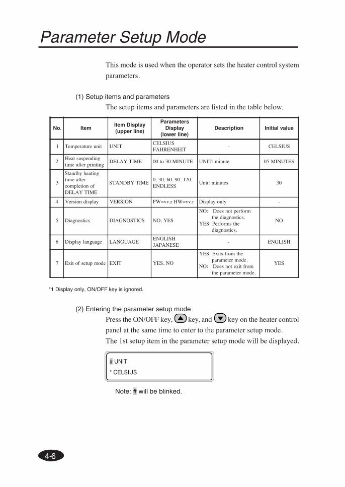
LCD Messages and Printer State
This section explains the messages shown on the LCD and outlines
menu operations.
Messages on the LCD
(1) Initialization display
The printer is being initialized.
Booting
*: When the system starts normally, both controllers go
online and enter idle mode automatically.
(2) Online state (idle mode) display
The printer can receive data from the computer.
PRINT READY
ROLL : 64” (PAPER)
Status display
Paper information
INITIALIZING
WAIT A MOMENT
*: When the key is pressed in the menu mode,
"CLEANING" menu appears.
1-21
Sec
tion
1 G
ettin
g S
tart
ed (
Bas
ic k
now
ledg
e)
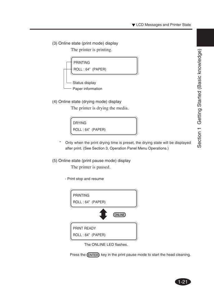
(3) Online state (print mode) display
The printer is printing.
PRINTING
ROLL : 64” (PAPER)
Status display
Paper information
LCD Messages and Printer State
(5) Online state (print pause mode) display
The printer is paused.
- Print stop and resume
PRINTING
ROLL : 64” (PAPER)
PRINT READY
ROLL : 64” (PAPER)
The ONLINE LED flashes.
Press the key in the print pause mode to start the head cleaning.
(4) Online state (drying mode) display
The printer is drying the media.
DRYING
ROLL : 64” (PAPER)
* Only when the print drying time is preset, the drying state will be displayed
after print. (See Section 3, Operation Panel Menu Operations.)
1-22
TOTAL CT XXXX
(6) Online state (print information mode) display
Paper total count and ink removing amount are displayed.
Bk INK REST: XXX%
Lm INK REST: XXX%
PRINT READY
ROLL : 64” (COATED)
Lc INK REST: XXX%
Y INK REST: XXX%
Three-secondintervals or
M INK REST: XXX%
C INK REST: XXX%
Three-secondintervals or
Then, the printer returns to online idle mode.
PRINT READY
ROLL : 64” (PAPER)
PRINT READY
ROLL : 64” (PAPER)
- Print cancel (end)
The ONLINE LED flashes.
1-23
Sec
tion
1 G
ettin
g S
tart
ed (
Bas
ic k
now
ledg
e)
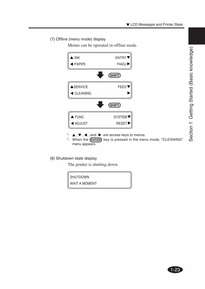
(8) Shutdown state display
The printer is shutting down.
SHUTDOWN
WAIT A MOMENT
(7) Offline (menu mode) display
Menus can be operated in offline mode.
*: , , , and are access keys to menus.*: When the key is pressed in the menu mode, "CLEANING"
menu appears.
INK ENTRY
PAPER F•ADJ
SERVICE FEED
CLEANING
FUNC SYSTEM
ADJUST RESET
LCD Messages and Printer State
1-24
2-1
Sec
tion
2 B
asic
Ope
ratio
ns
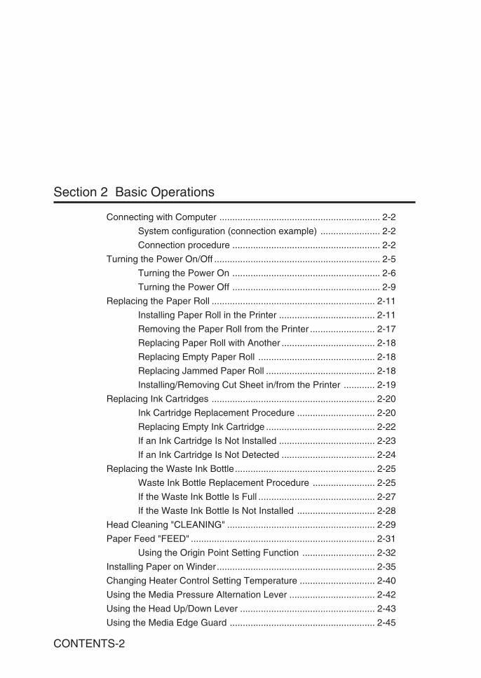
Connecting with ComputerSystem configuration (connection example)Connection procedure
Turning the Power On/OffTurning the Power OnTurning the Power Off
Replacing the Paper RollInstalling Paper Roll in the PrinterRemoving the Paper Roll from the PrinterReplacing Paper Roll with AnotherReplacing Empty Paper RollReplacing Jammed Paper RollInstalling/Removing Cut Sheet in/from the Printer
Replacing Ink CartridgesInk Cartridge Replacement ProcedureReplacing Empty Ink CartridgeIf an Ink Cartridge Is Not InstalledIf an Ink Cartridge Is Not Detected
Replacing the Waste Ink BottleWaste Ink Bottle Replacement ProcedureIf the Waste Ink Bottle Is FullIf the Waste Ink Bottle Is Not Installed
Head Cleaning "CLEANING"Paper Feed "FEED"
Using the Origin Point Setting FunctionInstalling Paper on WinderChanging Heater Control Setting TemperatureUsing the Media Pressure Alternation LeverUsing the Head Up/Down LeverUsing the Media Edge GuardUsing the FAN Guard Positioning BarUsing the Print Pause/Restart and Cancel KeysInspection & Maintenance
Contents of this section
Section 2 Basic Operations
2-2
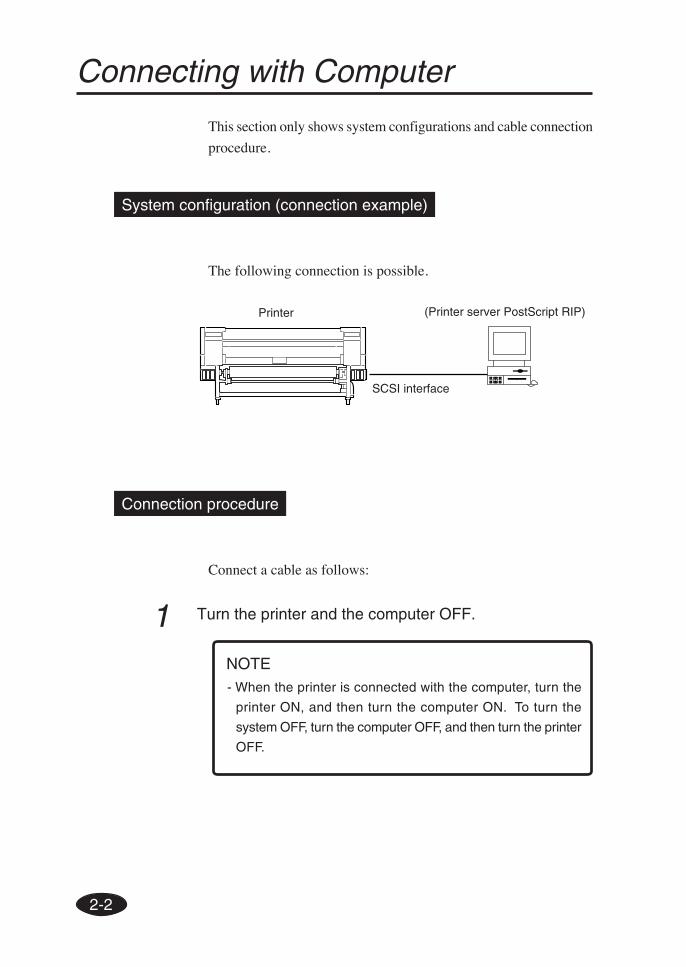
Connecting with Computer
This section only shows system configurations and cable connection
procedure.
System configuration (connection example)
The following connection is possible.
Connection procedure
Connect a cable as follows:
1 Turn the printer and the computer OFF.
Printer (Printer server PostScript RIP)
SCSI interface
NOTE- When the printer is connected with the computer, turn the
printer ON, and then turn the computer ON. To turn the
system OFF, turn the computer OFF, and then turn the printer
OFF.
2-3
Sec
tion
2 B
asic
Ope
ratio
ns
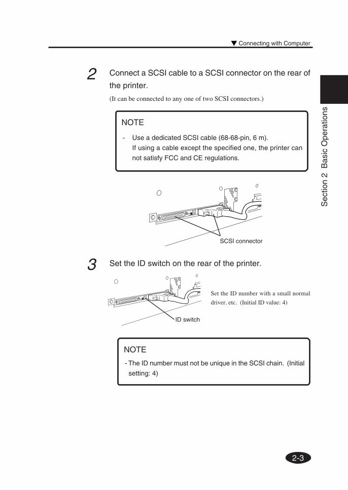
3 Set the ID switch on the rear of the printer.
- The ID number must not be unique in the SCSI chain. (Initial
setting: 4)
SCSI connector
NOTE
- Use a dedicated SCSI cable (68-68-pin, 6 m).
If using a cable except the specified one, the printer can
not satisfy FCC and CE regulations.
ID switch
Set the ID number with a small normal
driver, etc. (Initial ID value: 4)
2 Connect a SCSI cable to a SCSI connector on the rear of
the printer.
(It can be connected to any one of two SCSI connectors.)
Connecting with Computer
NOTE
2-4
4 Set the terminator on the rear of the printer to ON or OFF.
The printer has the SCSI terminator ON/OFF function. If the external
terminator is not used and the printer is a terminating device in the SCSI
chain (only one SCSI connector is connected), set the terminator switch to
ON. If the printer is not a terminating device, set it to OFF.
Terminator switch
2-5
Sec
tion
2 B
asic
Ope
ratio
ns
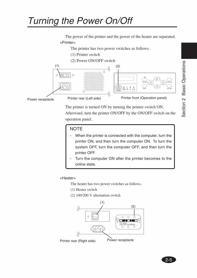
Turning the Power On/Off
The power of the printer and the power of the heater are separated.
<Printer>
The printer has two power switches as follows.
(1) Printer switch
(2) Power ON/OFF switch
The printer is turned ON by turning the printer switch ON.
Afterward, turn the printer ON/OFF by the ON/OFF switch on the
operation panel.
<Heater>
The heater has two power switches as follows.
(1) Heater switch
(2) 100/200 V alternation switch
Printer rear (Right side)
NOTE- When the printer is connected with the computer, turn the
printer ON, and then turn the computer ON. To turn the
system OFF, turn the computer OFF, and then turn the
printer OFF.
- Turn the computer ON after the printer becomes to the
online state.
(1)
Power receptacle Printer rear (Left side)
(1)
Power receptacle
(2)
For Heater100-120V 12A 50/60Hz
(2)
Printer front (Operation panel)
2-6
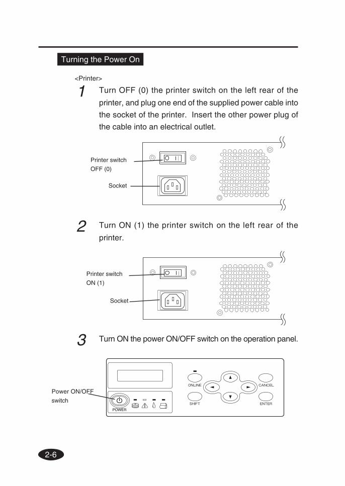
3 Turn ON the power ON/OFF switch on the operation panel.
Power ON/OFF
switch
Turning the Power On
<Printer>
1 Turn OFF (0) the printer switch on the left rear of the
printer, and plug one end of the supplied power cable into
the socket of the printer. Insert the other power plug of
the cable into an electrical outlet.
2 Turn ON (1) the printer switch on the left rear of the
printer.
Printer switch
OFF (0)
Socket
Printer switch
ON (1)
Socket
2-7
Sec
tion
2 B
asic
Ope
ratio
ns
Booting
PRINT READY
ROLL : 64” (PAPER)
INITIALIZING
WAIT A MOMENT
NOTE- Turn OFF the printer while “PRINT READY” is displayed on
the LCD panel except emergency.
Do not turn OFF the printer while “INITIALIZING” or
“CLEANING” is displayed on the LCD panel to avoid drop of
the ink and damage of the head.
Turning the Power On/Off
If a 64" paper roll is used
The heater control panel is displayed by turning the printer power ON.
However, turn the heater power ON to use the heater.
When the heater power is turned OFF, the following message is displayed
on the heater control panel.
TURN ON
THE HEATER
- If the fan does not run or the operation panel lamp does notlight when the printer switch and power ON/OFF switch onthe operational panel are turned ON, the power supply maybe faulty.
- If an error is detected during the self-diagnostic test atpowering on, an error message appears on the LCD. Seethe Section 5, Troubleshooting and take an appropriatemeasure.
HINT
When the switch is turned ON, a power-on self-diagnostic test is performed
and the following message appears on the LCD on the operation panel.
2-8
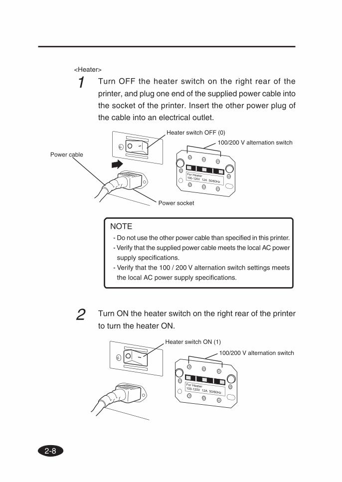
<Heater>
1 Turn OFF the heater switch on the right rear of the
printer, and plug one end of the supplied power cable into
the socket of the printer. Insert the other power plug of
the cable into an electrical outlet.
2 Turn ON the heater switch on the right rear of the printer
to turn the heater ON.
Heater switch OFF (0)
Power socket
Power cable
Heater switch ON (1)
100/200 V alternation switch
100/200 V alternation switch
- Do not use the other power cable than specified in this printer.
- Verify that the supplied power cable meets the local AC power
supply specifications.
- Verify that the 100 / 200 V alternation switch settings meets
the local AC power supply specifications.
NOTE
2-9
Sec
tion
2 B
asic
Ope
ratio
ns
Turning the Power Off
<Printer>
1 Turn OFF the power ON/OFF switch on the operation
panel for a couple of seconds.
The above message is displayed on the LCD to indicate that a
shutdown process is in progress. After the process ends, the power
is turned OFF.
The fill cap (filling ink into the cap unit) is performed automatically
to maintain good head condition at turning off the printer.
Press the and the ON/OFF keys to skip the fill cap at turning
off the printer.
Performing the fill cap operation is recommended.
- The printer switch on the rear of the printer should be used
only when the printer is turned OFF completely in order to
move it, connect it with a computer, install or maintain its
parts.
- Turn the power ON/OFF switch OFF, wait for at least ten
seconds, then turn it ON again.
- The printer performs fill cap operation to keep the good
head condition at first 20 hours after print wait state and
every 3 days.
It is recommended to keep the printer ON.
SHUTDOWN
WAIT A MOMENT
CAUTION
Turning the Power On/Off
MJAN
Text Box
Necessary for Power Supply protection
MJAN
Text Box
Fill cap done: After Printer switched on and in standby: - First time after 20 hours - Then every 3 days After Printer switched off: - 1 Time during switch down procedure
MJAN
Rectangle
2-10
Heater switch
OFF (0)
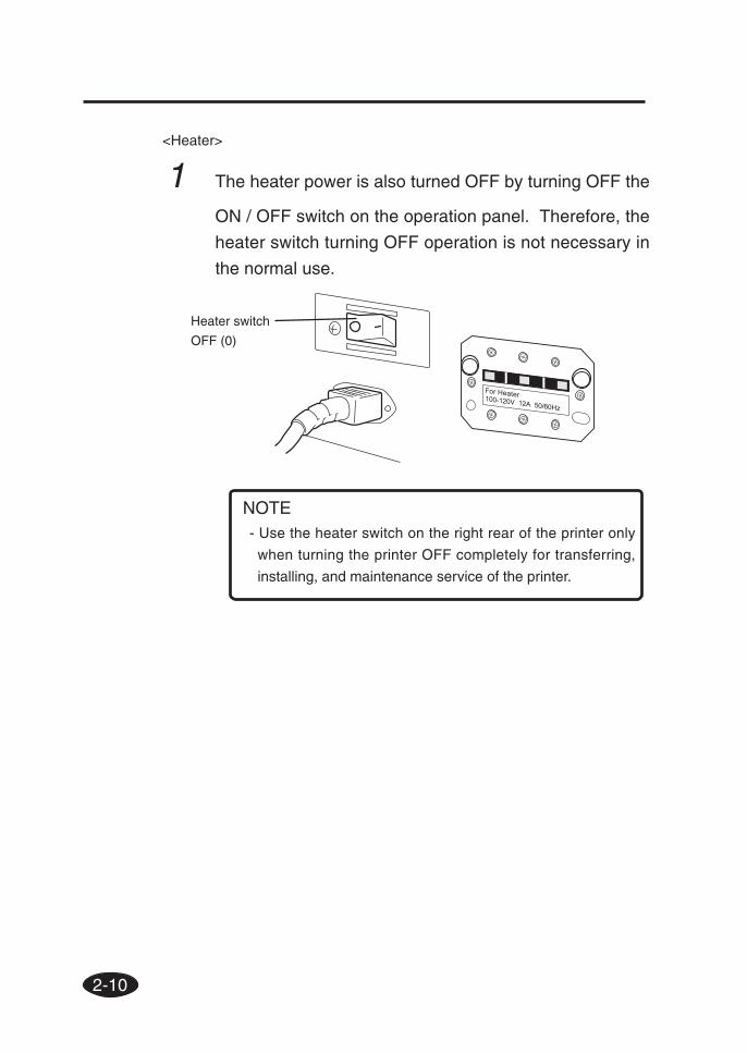
<Heater>
1 The heater power is also turned OFF by turning OFF the
ON / OFF switch on the operation panel. Therefore, the
heater switch turning OFF operation is not necessary in
the normal use.
- Use the heater switch on the right rear of the printer only
when turning the printer OFF completely for transferring,
installing, and maintenance service of the printer.
NOTE
2-11
Sec
tion
2 B
asic
Ope
ratio
ns
Replacing the Paper Roll
This section describes how to install a paper roll in the printer, and
remove it from the printer.
A paper roll is replaced in the following three cases:
- If a paper roll is replaced with another
- If it is replaced when it runs out
- If it is replaced when it jams
A paper replacement procedure in each case is explained below:
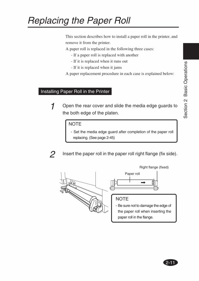
Installing Paper Roll in the Printer
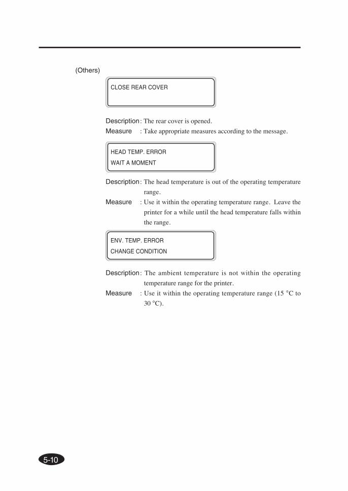
1 Open the rear cover and slide the media edge guards to
the both edge of the platen.
2 Insert the paper roll in the paper roll right flange (fix side).
Paper roll
Right flange (fixed)
- Be sure not to damage the edge of
the paper roll when inserting the
paper roll in the flange.
NOTE
- Set the media edge guard after completion of the paper roll
replacing. (See page 2-45)
NOTE
2-12
4 Tighten the left flange knob securely.
Pull the winder sensor lever to front side.
5 Lift the pressure roller up/down lever.
Left flange knob
Winder sensor lever
Head up/down lever
Paper rollLeft flange (movable)
Be sure not to catch
your finger in the rail of
the flange.
CAUTION
3 Slide the left flange (movable side) and put it into the
paper roll.
2-13
Sec
tion
2 B
asic
Ope
ratio
ns
Replacing the Paper Roll
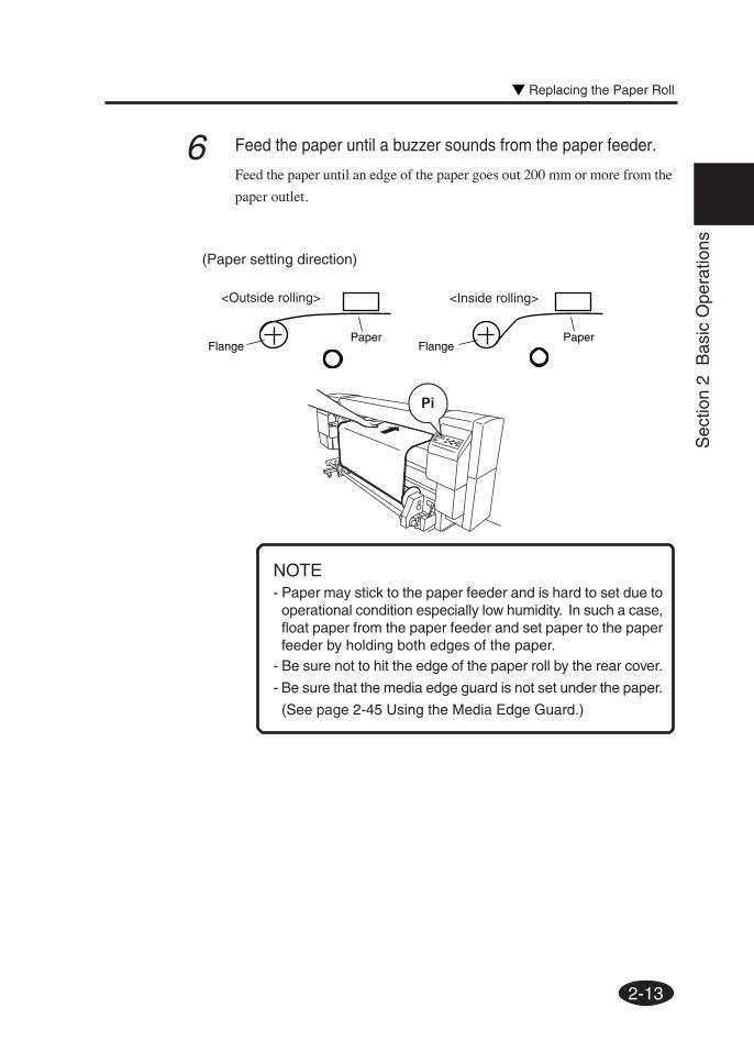
(Paper setting direction)
FlangePaper
FlangePaper
<Outside rolling> <Inside rolling>
NOTE
6 Feed the paper until a buzzer sounds from the paper feeder.
Feed the paper until an edge of the paper goes out 200 mm or more from the
paper outlet.
- Paper may stick to the paper feeder and is hard to set due tooperational condition especially low humidity. In such a case,float paper from the paper feeder and set paper to the paperfeeder by holding both edges of the paper.
- Be sure not to hit the edge of the paper roll by the rear cover.
- Be sure that the media edge guard is not set under the paper.
(See page 2-45 Using the Media Edge Guard.)
2-14
7 When feeding a paper roll, hold it at the center and
rewind the flange to take up the slack in the paper.
The guide line on the printer is no more than a guide
line. Install paper roll on the printer in a straight line
against the paper roll.
The paper roll should not be inserted in the right of the perforated line.
If the paper roll is inserted in the right of the perforated line, adjust the
flange position.
8 Push down the pressure roller up/down lever.
Perform operations according to the guidance message shown on the LCD.
Pressure up/down lever
9 Confirm the media edge guard setting again.
Confirm whether the media edge guard does not goes down of the
paper.
Confirm the position of the media edge guard and press the
key.
CHECK EDGE GUARD
*OK?
2-15
Sec
tion
2 B
asic
Ope
ratio
ns
Replacing the Paper Roll
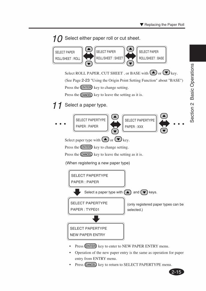
10 Select either paper roll or cut sheet.
Select ROLL PAPER, CUT SHEET , or BASE with or key.
(See Page 2-23 "Using the Origin Point Setting Function" about "BASE")
Press the key to change setting.
Press the key to leave the setting as it is.
SELECT PAPER
ROLL/SHEET : SHEET
SELECT PAPER
ROLL/SHEET : BASE
SELECT PAPER
ROLL/SHEET : ROLL
○ ○ ○
(When registering a new paper type)
SELECT PAPERTYPE
PAPER : PAPER
Select a paper type with and keys.
11 Select a paper type.
Select paper type with or key.
Press the key to change setting.
Press the key to leave the setting as it is.
SELECT PAPERTYPE
PAPER : PAPER
SELECT PAPERTYPE
PAPER : XXX○ ○ ○
• Press key to enter to NEW PAPER ENTRY menu.
• Operation of the new paper entry is the same as operation for paper
entry from ENTRY menu.
• Press key to return to SELECT PAPERTYPE menu.
SELECT PAPERTYPE
PAPER : TYPE01
SELECT PAPERTYPE
NEW PAPER ENTRY
(only registered paper types can be
selected.)
2-16
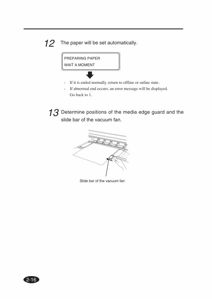
PREPARING PAPER
WAIT A MOMENT
- If it is ended normally, return to offline or online state.
- If abnormal end occurs, an error message will be displayed.
Go back to 1.
12 The paper will be set automatically.
13 Determine positions of the media edge guard and the
slide bar of the vacuum fan.
Slide bar of the vacuum fan
2-17
Sec
tion
2 B
asic
Ope
ratio
ns
Removing the Paper Roll from the Printer
1 Lift the pressure roller up/down lever.
2 Loose the left flange knob, pull out the paper roll from the
flange, and remove the paper roll from the printer.
Pressure roller up/down lever
Left flange Paper roll Right flange
Flange knob
(2)(3)
(1)(4)
Replacing the Paper Roll
2-18
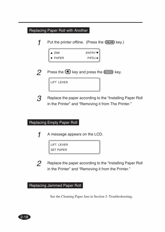
Replacing Paper Roll with Another
1 Put the printer offline. (Press the key.)
2 Press the key and press the key.
3 Replace the paper according to the “Installing Paper Roll
in the Printer” and “Removing it from The Printer.”
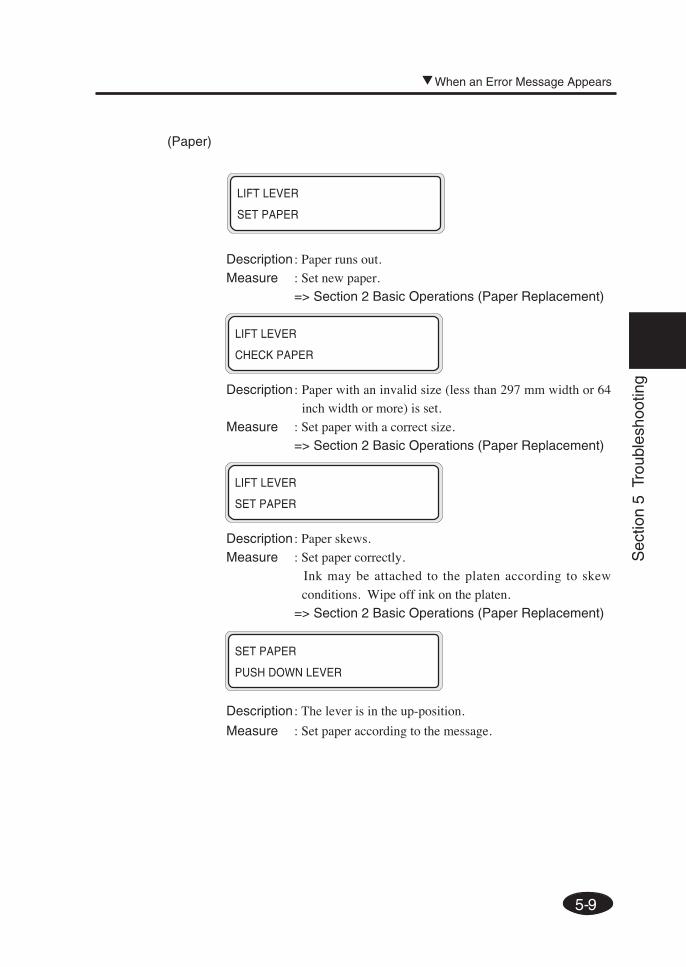
Replacing Empty Paper Roll
1 A message appears on the LCD.
2 Replace the paper according to the “Installing Paper Roll
in the Printer” and “Removing it from the Printer.”
LIFT LEVER
SET PAPER
Replacing Jammed Paper Roll
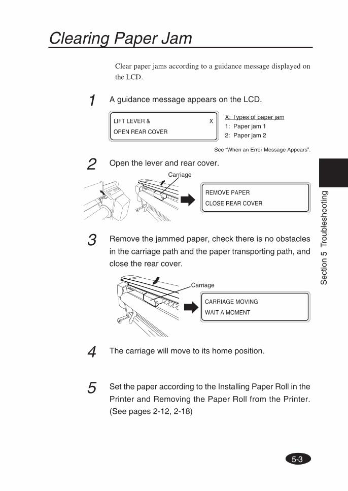
See the Cleaning Paper Jam in Section 5, Troubleshooting.
LIFT LEVER
ZNK ENTRY
PAPER F•FDJ
2-19
Sec
tion
2 B
asic
Ope
ratio
ns
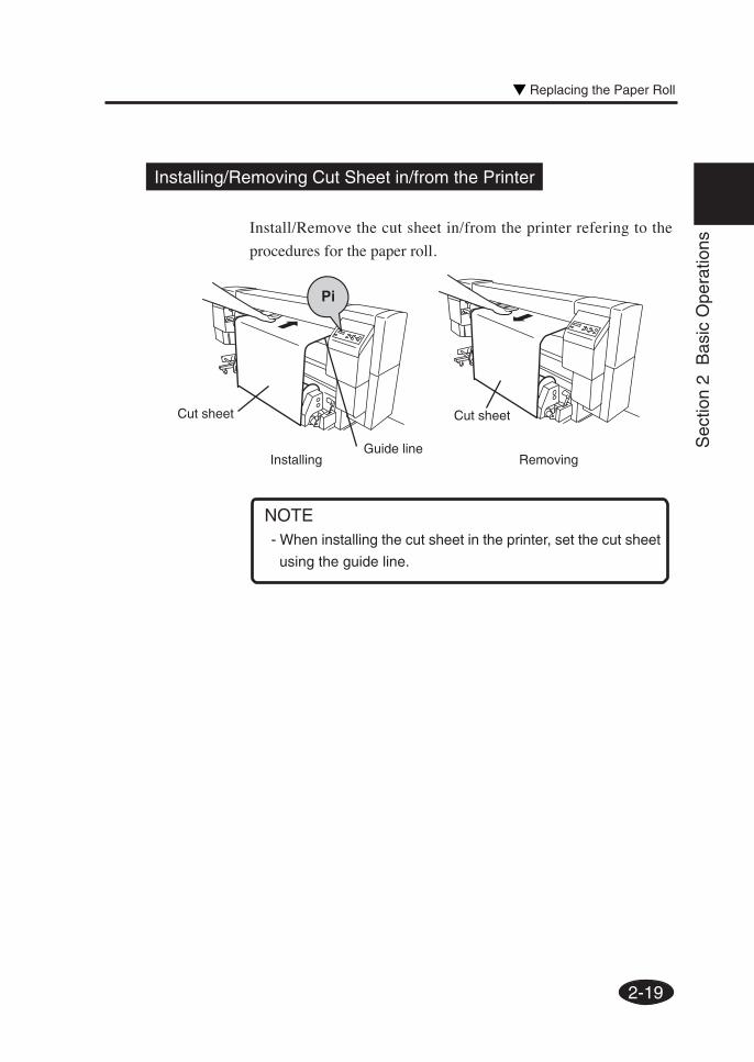
Installing/Removing Cut Sheet in/from the Printer
Install/Remove the cut sheet in/from the printer refering to the
procedures for the paper roll.
Installing Removing
- When installing the cut sheet in the printer, set the cut sheet
using the guide line.
NOTE
Cut sheet
Guide line
Cut sheet
Replacing the Paper Roll
2-20
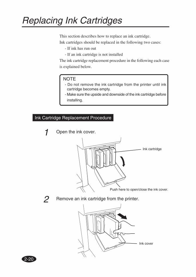
Replacing Ink Cartridges
This section describes how to replace an ink cartridge.
Ink cartridges should be replaced in the following two cases:
- If ink has run out
- If an ink cartridge is not installed
The ink cartridge replacement procedure in the following each case
is explained below.
Ink Cartridge Replacement Procedure
1 Open the ink cover.
2 Remove an ink cartridge from the printer.
Ink cartridge
- Do not remove the ink cartridge from the printer until inkcartridge becomes empty.
- Make sure the upside and downside of the ink cartridge before
installing.
NOTE
Ink cover
Push here to open/close the ink cover.
2-21
Sec
tion
2 B
asic
Ope
ratio
ns
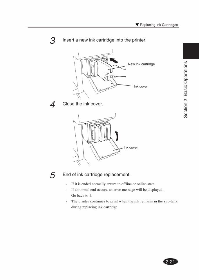
3 Insert a new ink cartridge into the printer.
4 Close the ink cover.
5 End of ink cartridge replacement.
- If it is ended normally, return to offline or online state.
- If abnormal end occurs, an error message will be displayed.
Go back to 1.
- The printer continues to print when the ink remains in the sub-tank
during replacing ink cartridge.
New ink cartridge
Ink cover
Ink cover
Replacing Ink Cartridges
2-22
Replacing Empty Ink Cartridge
1 A guidance message appears.
2 Replace the ink cartridge according to the “Ink Cartridge
Replacement Procedure.”
OPEN R INKCOVER
CHANGE XX INK
XX: Ink name
C: CYAN
M: MAGENTA
Y: YELLOW
OPEN L INKCOVER
CHANGE XX INK
XX: Ink name
Bk: BLACK
Lm: LIGHT MAGENTA
Lc: LIGHT CYAN
2-23
Sec
tion
2 B
asic
Ope
ratio
ns
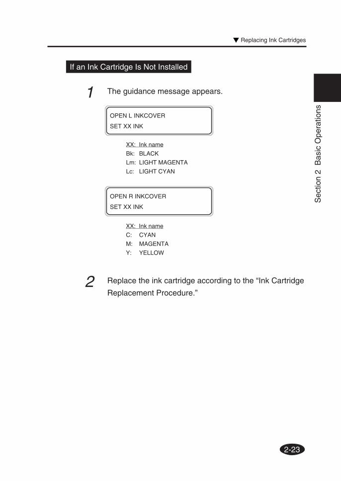
If an Ink Cartridge Is Not Installed
1 The guidance message appears.
2 Replace the ink cartridge according to the “Ink Cartridge
Replacement Procedure.”
OPEN R INKCOVER
SET XX INK
XX: Ink name
C: CYAN
M: MAGENTA
Y: YELLOW
OPEN L INKCOVER
SET XX INK
XX: Ink name
Bk: BLACK
Lm: LIGHT MAGENTA
Lc: LIGHT CYAN
Replacing Ink Cartridges
2-24
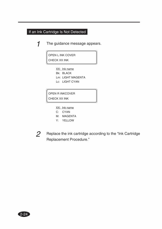
If an Ink Cartridge Is Not Detected
1 The guidance message appears.
2 Replace the ink cartridge according to the “Ink Cartridge
Replacement Procedure.”
OPEN R INKCOVER
CHECK XX INK
XX: Ink name
C: CYAN
M: MAGENTA
Y: YELLOW
OPEN L INK COVER
CHECK XX INK
XX: Ink name
Bk: BLACK
Lm: LIGHT MAGENTA
Lc: LIGHT CYAN
2-25
Sec
tion
2 B
asic
Ope
ratio
ns
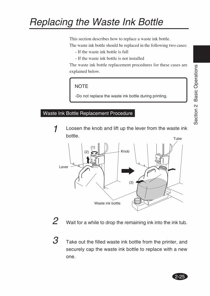
Replacing the Waste Ink Bottle
This section describes how to replace a waste ink bottle.
The waste ink bottle should be replaced in the following two cases:
- If the waste ink bottle is full
- If the waste ink bottle is not installed
The waste ink bottle replacement procedures for these cases are
explained below.
-Do not replace the waste ink bottle during printing.
Waste Ink Bottle Replacement Procedure
1 Loosen the knob and lift up the lever from the waste ink
bottle.
2 Wait for a while to drop the remaining ink into the ink tub.
3 Take out the filled waste ink bottle from the printer, and
securely cap the waste ink bottle to replace with a new
one.
Waste ink bottle
NOTE
(1)(2)
(3)
Lever
Knob
Tube
2-26
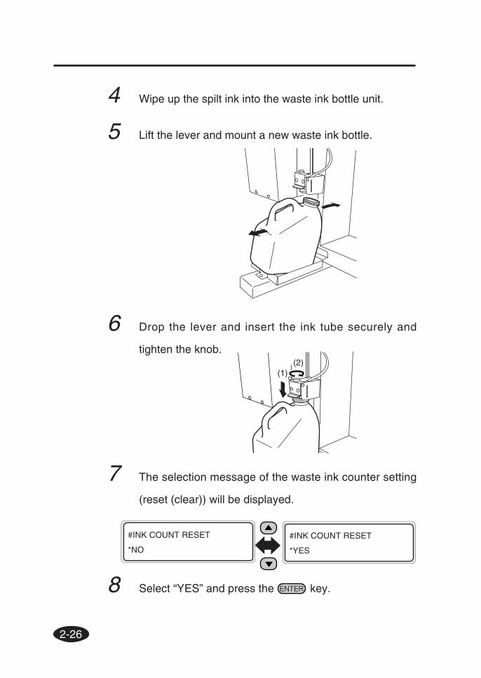
4 Wipe up the spilt ink into the waste ink bottle unit.
5 Lift the lever and mount a new waste ink bottle.
6 Drop the lever and insert the ink tube securely and
tighten the knob.
7 The selection message of the waste ink counter setting
(reset (clear)) will be displayed.
8 Select “YES” and press the key.
#INK COUNT RESET
*NO
#INK COUNT RESET
*YES
(1)(2)
2-27
Sec
tion
2 B
asic
Ope
ratio
ns
2 The selection message of the waste ink counter setting
(reset (clear)) will be displayed.
- The waste ink counter is prepared for urging waste ink
disposal with the error message when the waste ink is more
than the specified amount by counting the used (waste)
ink amount.
The waste ink counter can detect full of the waste
simultaneously but cannot detect actual full state of the
waste ink.
The counter counts up from the empty of the waste ink
bottle. Always select “*YES” for the “INK COUTN RESET”
menu when replacing the waste ink bottle with a new one.
If not, the waste ink full counter cannot be only used
effectively, but also the waste ink becomes full before
generating warning and the waste ink may be spilt over.
3 Select “*YES’ and press the key.
#INK COUNT RESET
*NO
#INK COUNT RESET
*YES
NOTE
If the Waste Ink Bottle Is Full
1 Replace the waste ink bottle according to the “Waste Ink
Bottle Replacement Procedure.”
- Make sure visually whether or not the waste ink bottle is
not full before using the printer.
NOTE
Replacing the Waste Ink Bottle
2-28
If the Waste Ink Bottle Is Not Installed
1 A guidance message appears on the LCD.
2 Insert a new waste ink bottle into the printer and install
the waste ink bottle cover.
⇒ See the step 3 of the Waste Ink Bottle Replacement
Procedure.
3 The selection message of the waste ink counter setting
(rest (clear)) will be displayed.
4 Select “*YES’ and press the key.
BOTTLE ISN’T SET
SET BOTTLE
#INK COUNT RESET
*NO
#INK COUNT RESET
*YES
2-29
Sec
tion
2 B
asic
Ope
ratio
ns
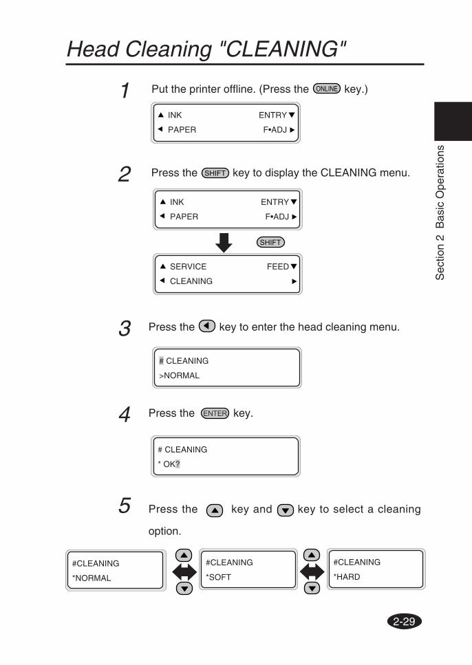
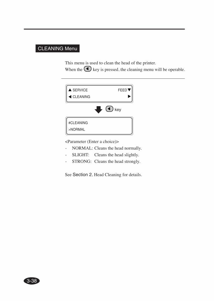
Head Cleaning "CLEANING"
1 Put the printer offline. (Press the key.)
2 Press the key to display the CLEANING menu.
3 Press the key to enter the head cleaning menu.
4 Press the key.
INK ENTRY
PAPER F•ADJ
INK ENTRY
PAPER F•ADJ
SERVICE FEED
CLEANING
# CLEANING
>NORMAL
# CLEANING
* OK?
5 Press the key and key to select a cleaning
option.
#CLEANING
*NORMAL
#CLEANING
*SOFT
#CLEANING
*HARD
2-30
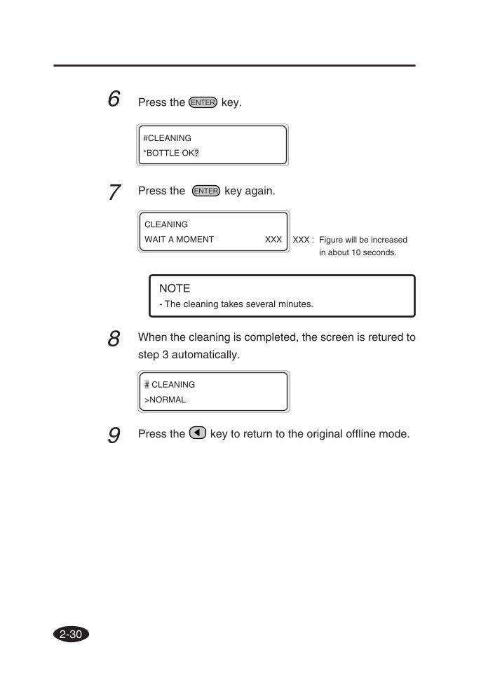
6 Press the key.
7 Press the key again.
NOTE- The cleaning takes several minutes.
8 When the cleaning is completed, the screen is retured to
step 3 automatically.
9 Press the key to return to the original offline mode.
CLEANING
WAIT A MOMENT XXX
# CLEANING
>NORMAL
XXX : Figure will be increased
in about 10 seconds.
#CLEANING
*BOTTLE OK?
2-31
Sec
tion
2 B
asic
Ope
ratio
ns
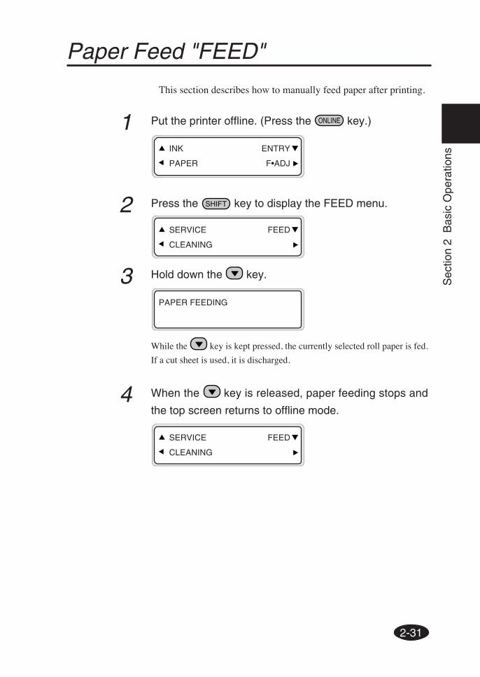
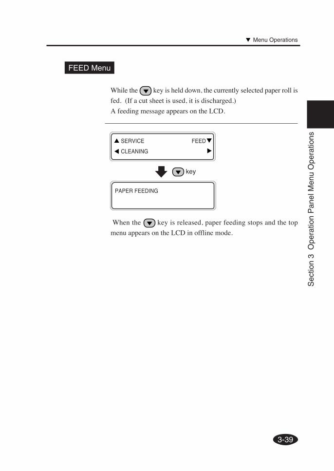
Paper Feed "FEED"
This section describes how to manually feed paper after printing.
1 Put the printer offline. (Press the key.)
2 Press the key to display the FEED menu.
3 Hold down the key.
While the key is kept pressed, the currently selected roll paper is fed.
If a cut sheet is used, it is discharged.
4 When the key is released, paper feeding stops and
the top screen returns to offline mode.
PAPER FEEDING
SERVICE FEED
CLEANING
SERVICE FEED
CLEANING
INK ENTRY
PAPER F•ADJ
2-32
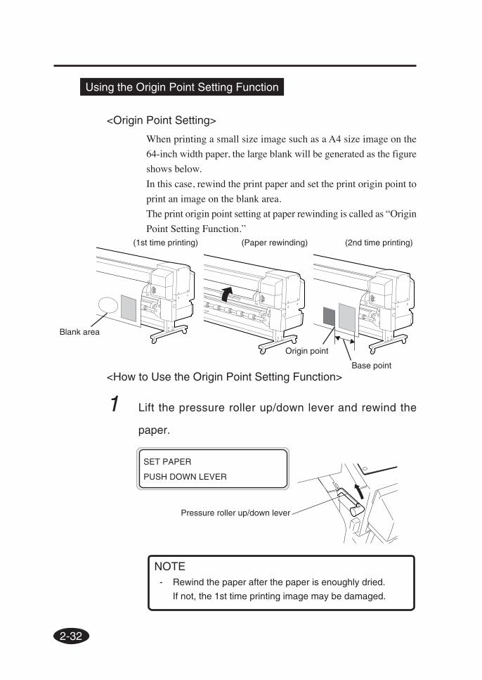
Using the Origin Point Setting Function
<Origin Point Setting>
When printing a small size image such as a A4 size image on the
64-inch width paper, the large blank will be generated as the figure
shows below.
In this case, rewind the print paper and set the print origin point to
print an image on the blank area.
The print origin point setting at paper rewinding is called as “Origin
Point Setting Function.”(1st time printing) (Paper rewinding) (2nd time printing)
<How to Use the Origin Point Setting Function>
1 Lift the pressure roller up/down lever and rewind the
paper.
- Rewind the paper after the paper is enoughly dried.
If not, the 1st time printing image may be damaged.
SET PAPER
PUSH DOWN LEVER
NOTE
Blank area
Pressure roller up/down lever
Origin point
Base point
2-33
Sec
tion
2 B
asic
Ope
ratio
ns
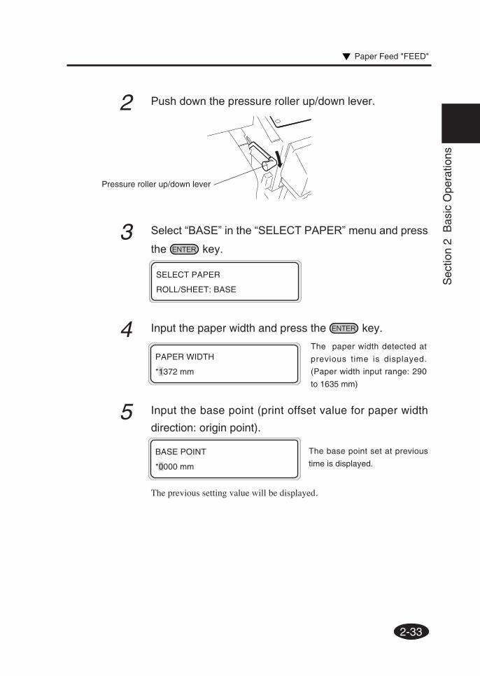
2 Push down the pressure roller up/down lever.
3 Select “BASE” in the “SELECT PAPER” menu and press
the key.
4 Input the paper width and press the key.
5 Input the base point (print offset value for paper width
direction: origin point).
The previous setting value will be displayed.
PAPER WIDTH
*1372 mm
BASE POINT
*0000 mm
SELECT PAPER
ROLL/SHEET: BASE
Pressure roller up/down lever
The paper width detected at
previous time is displayed.
(Paper width input range: 290
to 1635 mm)
The base point set at previous
time is displayed.
Paper Feed "FEED"
2-34
7 Select a paper type again.
- When using the origin point setting function, keep front,
right, and left margins sufficiently because the paper is
rewinded manually.
- The paper width and base point settings cannot be saved.
- The origin point setting function can be used only for paper
roll. This function cannot be used for the cut sheet.
SELECT PAPER TYPE
PAPER: TYPE01
PREPARING PAPER
WAIT A MOMENT
NOTE
PAPER FEED BACK
*NO
PAPER FEED BACK
*YES
The area from the paper outputsensor position to the print startposition (the grid roller) becomesprint dead area.
The pr int dead area can bedecreased by rewinding the paperfor length between the paper outputsensor and grid roller.(20 to 30 mm from the front edgecannot be printed.)
6 Select “*Yes” or “No” of back feed operation.
NOTE
- Cut the edge of the paper so that it will be parallel to the
guide line before installing the paper.
If the edge of the paper is not parallel to the guide line, the
front side of the print is cut, the platen is stained with ink,
and the paper jam may be caused.
2-35
Sec
tion
2 B
asic
Ope
ratio
ns
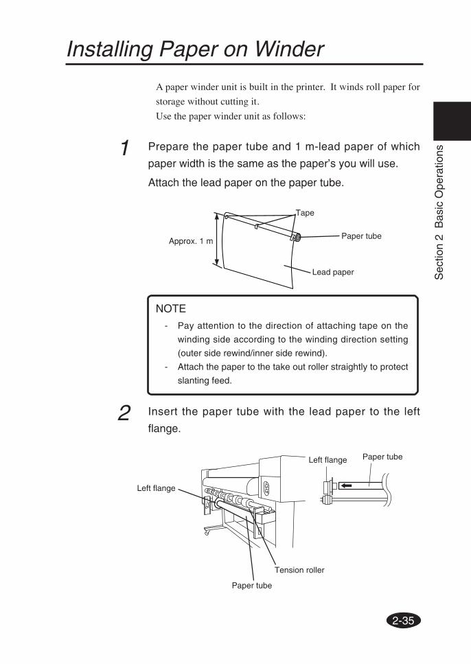
Installing Paper on Winder
A paper winder unit is built in the printer. It winds roll paper for
storage without cutting it.
Use the paper winder unit as follows:
1 Prepare the paper tube and 1 m-lead paper of which
paper width is the same as the paper’s you will use.
Attach the lead paper on the paper tube.
2 Insert the paper tube with the lead paper to the left
flange.
Left flange
Paper tube
Tension roller
Paper tubeLeft flange
Tape
Approx. 1 mPaper tube
Lead paper
- Pay attention to the direction of attaching tape on the
winding side according to the winding direction setting
(outer side rewind/inner side rewind).
- Attach the paper to the take out roller straightly to protect
slanting feed.
NOTE
2-36
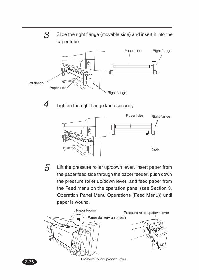
5 Lift the pressure roller up/down lever, insert paper from
the paper feed side through the paper feeder, push down
the pressure roller up/down lever, and feed paper from
the Feed menu on the operation panel (see Section 3,
Operation Panel Menu Operations (Feed Menu)) until
paper is wound.
Paper feeder
Paper delivery unit (rear)
4 Tighten the right flange knob securely.
Left flangePaper tube
Right flange
Paper tube Right flange
Right flange
3 Slide the right flange (movable side) and insert it into the
paper tube.
Paper tube
Knob
Pressure roller up/down lever
Pressure roller up/down lever
(2)(1)
(3)
2-37
Sec
tion
2 B
asic
Ope
ratio
ns
7 Manually turn the scroller flange in the direction of
winding to wind the paper slightly.
8 Check the positions of the paper and winding sensor,
and install it.
6 Tape the edge of the paper on the lead paper at three
positions: both sides and center.
Paper tube
Tape
Tension roller
Tension roller
Paper
Lead paper
Tape
Winder switch
Winder switch
Installing Paper on Winder
MJAN
Text Box
9 Check the position of the winder switch: Switch position Winding Outside Outside Centre Off Inside Inside
2-38
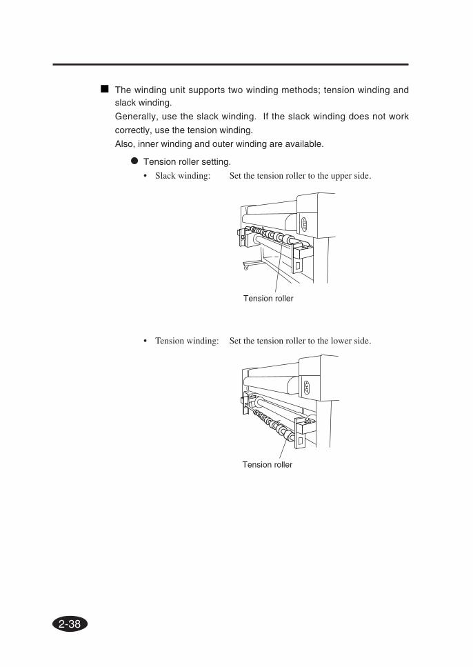
• Tension roller setting.
• Slack winding: Set the tension roller to the upper side.
• Tension winding: Set the tension roller to the lower side.
The winding unit supports two winding methods; tension winding andslack winding.
Generally, use the slack winding. If the slack winding does not work
correctly, use the tension winding.
Also, inner winding and outer winding are available.
Tension roller
Tension roller
2-39
Sec
tion
2 B
asic
Ope
ratio
ns
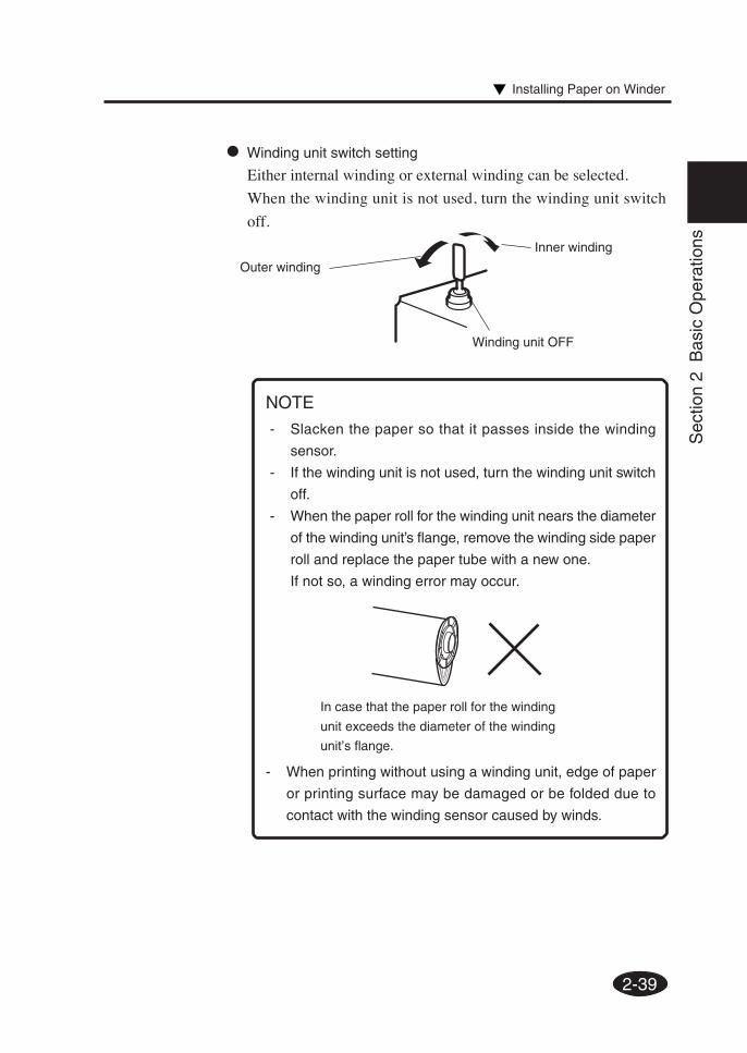
- Slacken the paper so that it passes inside the winding
sensor.
- If the winding unit is not used, turn the winding unit switch
off.
- When the paper roll for the winding unit nears the diameter
of the winding unit’s flange, remove the winding side paper
roll and replace the paper tube with a new one.
If not so, a winding error may occur.
NOTE
- When printing without using a winding unit, edge of paper
or printing surface may be damaged or be folded due to
contact with the winding sensor caused by winds.
In case that the paper roll for the winding
unit exceeds the diameter of the winding
unit’s flange.
Outer winding
Winding unit OFF
• Winding unit switch setting
Either internal winding or external winding can be selected.
When the winding unit is not used, turn the winding unit switch
off.
Inner winding
Installing Paper on Winder
2-40
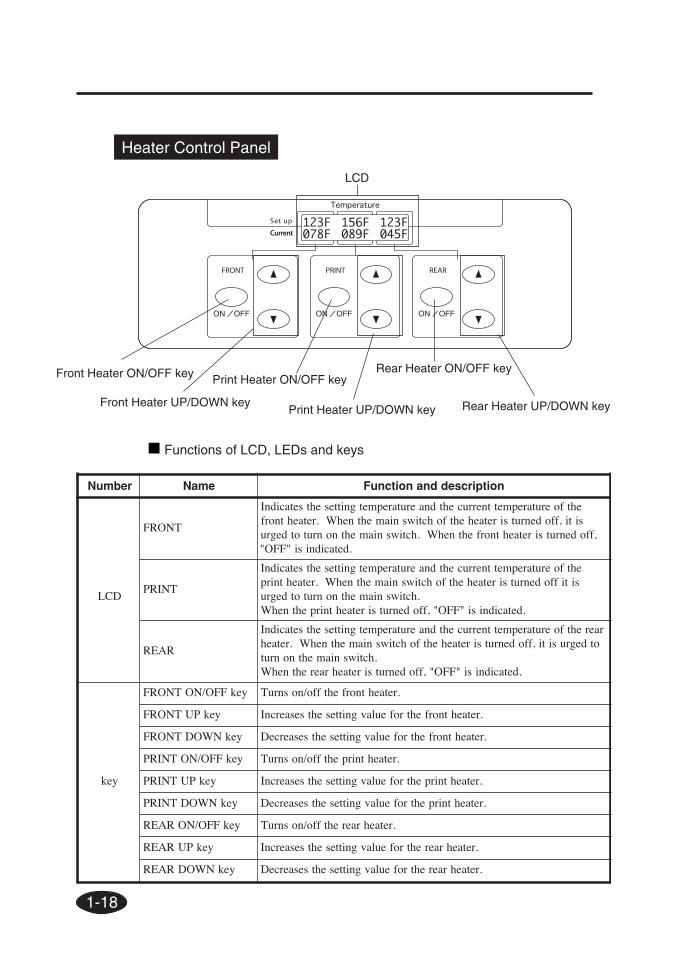
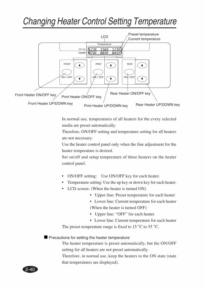
Changing Heater Control Setting Temperature
In normal use, temperatures of all heaters for the every selected
media are preset automatically.
Therefore, ON/OFF setting and temperature setting for all heaters
are not necessary.
Use the heater control panel only when the fine adjustment for the
heater temperature is desired.
Set on/off and setup temperature of three heaters on the heater
control panel.
• ON/OFF setting: Use ON/OFF key for each heater.
• Temperature setting: Use the up key or down key for each heater.
• LCD screen: (When the heater is turned ON)
• Upper line: Preset temperature for each heater
• Lower line: Current temperature for each heater
(When the heater is turned OFF)
• Upper line: “OFF” for each heater
• Lower line: Current temperature for each heater
The preset temperature range is fixed to 15 °C to 55 °C.
LCD
Print Heater ON/OFF key
Print Heater UP/DOWN key
Front Heater ON/OFF key
Front Heater UP/DOWN key
Rear Heater ON/OFF key
Rear Heater UP/DOWN key
Preset temperatureCurrent temperature
Precautions for setting the heater temperatureThe heater temperature is preset automatically, but the ON/OFF
setting for all heaters are not preset automatically.
Therefore, in normal use, keep the heaters to the ON state (state
that temperatures are displayed).
2-41
Sec
tion
2 B
asic
Ope
ratio
ns
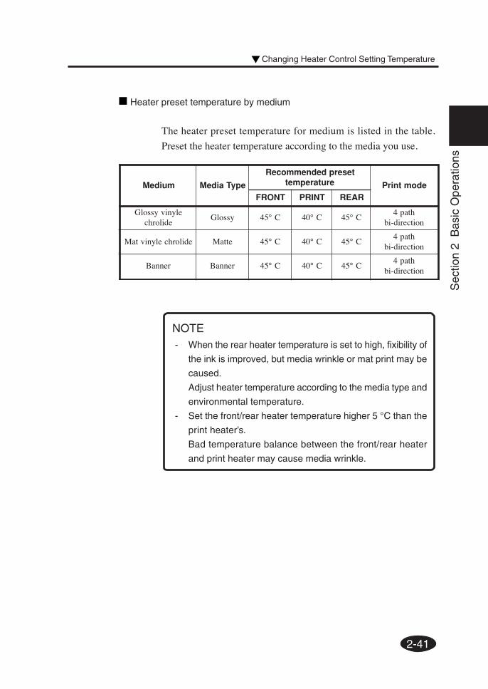
Heater preset temperature by medium
The heater preset temperature for medium is listed in the table.
Preset the heater temperature according to the media you use.
NOTE- When the rear heater temperature is set to high, fixibility of
the ink is improved, but media wrinkle or mat print may be
caused.
Adjust heater temperature according to the media type and
environmental temperature.
- Set the front/rear heater temperature higher 5 °C than the
print heater’s.
Bad temperature balance between the front/rear heater
and print heater may cause media wrinkle.
muideM epyTaideM
teserpdednemmoceRerutarepmet edomtnirP
TNORF TNIRP RAER
elynivyssolGedilorhc
yssolG C°54 C°04 C°54htap4
noitcerid-ib
edilorhcelynivtaM ettaM C°54 C°04 C°54htap4
noitcerid-ib
rennaB rennaB C°54 C°04 C°54htap4
noitcerid-ib
Changing Heater Control Setting Temperature
2-42
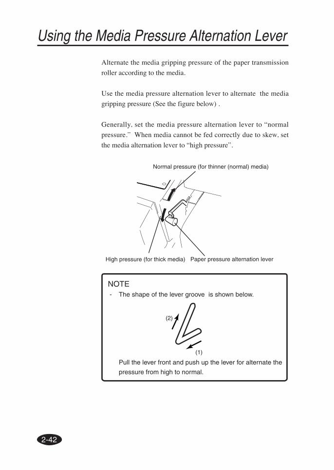
Using the Media Pressure Alternation Lever
Alternate the media gripping pressure of the paper transmission
roller according to the media.
Use the media pressure alternation lever to alternate the media
gripping pressure (See the figure below) .
Generally, set the media pressure alternation lever to “normal
pressure.” When media cannot be fed correctly due to skew, set
the media alternation lever to “high pressure”.
Normal pressure (for thinner (normal) media)
High pressure (for thick media)
NOTE- The shape of the lever groove is shown below.
Pull the lever front and push up the lever for alternate the
pressure from high to normal.
(1)
(2)
Paper pressure alternation lever
2-43
Sec
tion
2 B
asic
Ope
ratio
ns
Using the Head Up/Down Lever
Alternate the head height according to the media you use.
Use the head up/down lever for alternating the head height.
(See the figure below)
2 Open the cap cover and loosen the head fixing screws (2
pieces) with a screw driver.
3 Alternate the height of the head with the head up/down
lever.
Generally, preset the head up/down lever up for glossy vinyle chloride and
matted vinyle chloride, and preset the head up/down for banner and FF.
When the paper thickness is 0.5 mm or more, preset the head up/down lever
up regardless of media type.
When the head is rubbed with the media due to media floating, preset the
head up/down lever down even for the thinner media.
Head fixing screw
Head up/down lever
Cap cover
Up (for thinner media (standard))
Down (for thicker media)
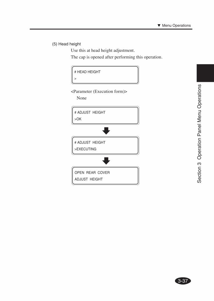
1 Enter SERVICE menu and execute HEAD HEIGHT ADJ
on the operation panel.
#ADJUST HEIGHT
>
#ADJUST HEIGHT
>EXECUTING
2-44
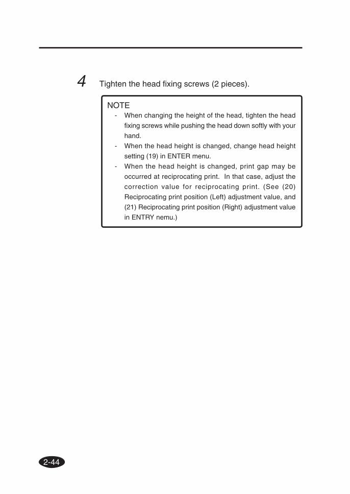
4 Tighten the head fixing screws (2 pieces).
- When changing the height of the head, tighten the head
fixing screws while pushing the head down softly with your
hand.
- When the head height is changed, change head height
setting (19) in ENTER menu.
- When the head height is changed, print gap may be
occurred at reciprocating print. In that case, adjust the
correction value for reciprocating print. (See (20)
Reciprocating print position (Left) adjustment value, and
(21) Reciprocating print position (Right) adjustment value
in ENTRY nemu.)
NOTE
2-45
Sec
tion
2 B
asic
Ope
ratio
ns
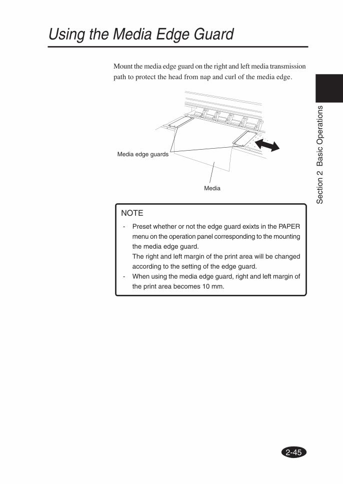
Media edge guards
Media
- Preset whether or not the edge guard exixts in the PAPER
menu on the operation panel corresponding to the mounting
the media edge guard.
The right and left margin of the print area will be changed
according to the setting of the edge guard.
- When using the media edge guard, right and left margin of
the print area becomes 10 mm.
NOTE
Mount the media edge guard on the right and left media transmission
path to protect the head from nap and curl of the media edge.
Using the Media Edge Guard
2-46
Using the FAN Guard Positioning Bar
Cut suction of the FAN for unused area to protect the head from
suction of the FAN.
Slide the FAN guard positioning bar between 50 inch width and 64
inch width.
Set the FAN guard positioning bar according to the media width
you use.
- When setting the FAN guard positioning bar for 50 inch
width media at 64 inch width media printing, the media
cannot be passed.
- Do not move the fan guard positioning bar during print.
If the fan guard positioning bar hits the media, paper jam
could be occurred.
NOTE
Paper
Slide bar
2-47
Sec
tion
2 B
asic
Ope
ratio
ns
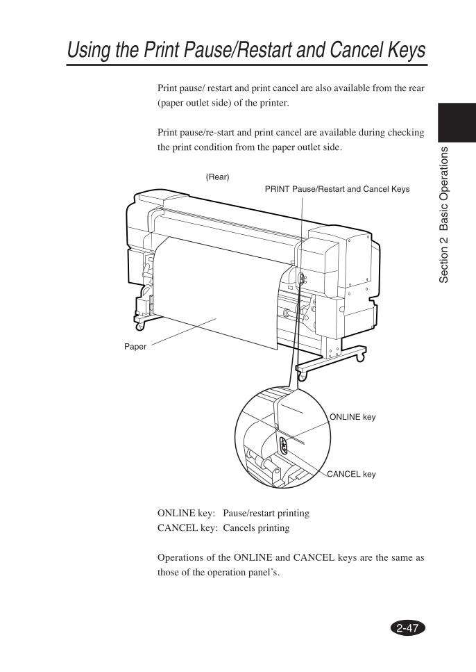
Using the Print Pause/Restart and Cancel Keys
Print pause/ restart and print cancel are also available from the rear
(paper outlet side) of the printer.
Print pause/re-start and print cancel are available during checking
the print condition from the paper outlet side.
ONLINE key: Pause/restart printing
CANCEL key: Cancels printing
Operations of the ONLINE and CANCEL keys are the same as
those of the operation panel’s.
(Rear)
PRINT Pause/Restart and Cancel Keys
Paper
ONLINE key
CANCEL key
2-48
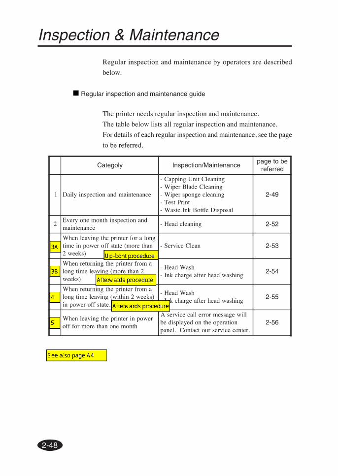
Inspection & Maintenance
Regular inspection and maintenance by operators are described
below.
Regular inspection and maintenance guide
The printer needs regular inspection and maintenance.
The table below lists all regular inspection and maintenance.
For details of each regular inspection and maintenance, see the page