U.S. NUCLEAR REGULATORY COMMISSION DOC N (2-76) & e. FILE NUM NRC DISTRIBUTION FOR PART 50 DOCKET MATERIAL ;j FROM: DATE OF DOCUMENT TO:Mr. E. Case Duke Power Co. 3-10-78 Charlotte, N.C. 28242 . DATE RECEIVED W. 0. Parker, Jr. 3-22-78 iLETT R ONOTORIZED PROP INPUT FORM NUMBER OF COPIES RECEIVED 4SORIGINAL ; JNCLASSIFIED O coPY DESCRIPTION Ltr trans the following: iP ENCLOSURE Description of a preliminary design concept & preliminary drawings of the over pressure system modification...... 20P est. REACTOR VESSEL OVERPRESSURIZATION DISTRIBUTION PER G. BECH 10-21-76 PLANT NAME:Oconee Units 1-2-3 JCM 3-31-78 + /.dCL. + /se7-i et)405 SAFETY FOR ACTION/INFORMATION eUT 70 (. eff BRANCH CHIEF: 7e5 /574 4 4;7 S AWd 11V I< 7 INTERNAL DISTRIBUTION E FILE 2 ?C/Afft  71 I & E (2) OELD__________ _ GOSSICK & STAFF BOSNAK PAWLICKI NOVAK ETSENHUT SHAO BAER BUTLER ZECH- *See o"itL__. EXTERNAL DISTRIBUTION CONTROL NUMBER TIC: 780900056 NSIC_ N ARS 195 (2 NRIC FORM 195 (2-76)
Transcript
U.S. NUCLEAR REGULATORY COMMISSION DOC N
(2-76) & e. FILE NUM
NRC DISTRIBUTION FOR PART 50 DOCKET MATERIAL ;j FROM: DATE OF DOCUMENT TO:Mr. E. Case Duke Power Co. 3-10-78
Charlotte, N.C. 28242 . DATE RECEIVED
W. 0. Parker, Jr. 3-22-78
iLETT R ONOTORIZED PROP INPUT FORM NUMBER OF COPIES RECEIVED
4SORIGINAL ; JNCLASSIFIED O coPY
DESCRIPTION Ltr trans the following: iP ENCLOSURE Description of a preliminary design
concept & preliminary drawings of the overpressure system modification...... 20P est.
REACTOR VESSEL OVERPRESSURIZATION DISTRIBUTION PER G. BECH 10-21-76
SAFETY FOR ACTION/INFORMATION eUT 70 (. eff BRANCH CHIEF: 7e5 /574 4 4;7 S AWd 11V I< 7
INTERNAL DISTRIBUTION
E FILE 2 ?C/Afft  71
I & E (2)
OELD__________ _
GOSSICK & STAFF
BOSNAK
PAWLICKI
NOVAK
ETSENHUT SHAO
BAER
BUTLER
ZECH- *See o"itL__.
EXTERNAL DISTRIBUTION CONTROL NUMBER
TIC: 780900056 NSIC_
N ARS 195 (2
NRIC FORM 195 (2-76)
DUKE POWER COMPANY POWER BUILDING
422 SOUTH CHURCH STREET, CHARLOTTE, N. C. 28242
WILLIAM 0. PARKERJR. March 10, 1978 VICE PRESIDENT TELEPHONE. AREA 704
STEAM PRODUCTION 373-4083
Mr. Edson G. Case, Acting Director Office of Nuclear Reactor Regulation U. S. Nuclear Regulatory Commission Washington, D. C. 20555
Attention: Mr. R. Reid, Chief 21 Operating Reactors Branch #4
ICOMMSS ION
Reference: Oconee Nuclear Station Docket Nos. 50-269, -270, -287
Dear Sir:
In your February 2, 1978 letter, additional information was requested
concerning a conceptual design of an overpressure protection system
modification. Please find attached a description of a preliminary
design concept and the preliminary drawings of the system modification.
This overpressure protection system is a conceptual design only. It
is our position that installation of this system would not provide any
significant, additional protection for the public's health and safety above that currently provided by installed protection systems and ad
ministrative procedures.
Very truly yours,
William 0. Parker, Jr. e 5? RLG:ge Attachments
7-80900056
ATTACHMENT 1
OVERPRESSURE PROTECTION SYSTEM PRELIMINARY DESIGN CONCEPT
The purpose of this design concept is to describe an additional redundant means to prevent an overpressurization incident caused by High Pressure Injection System (HPI) actuation.
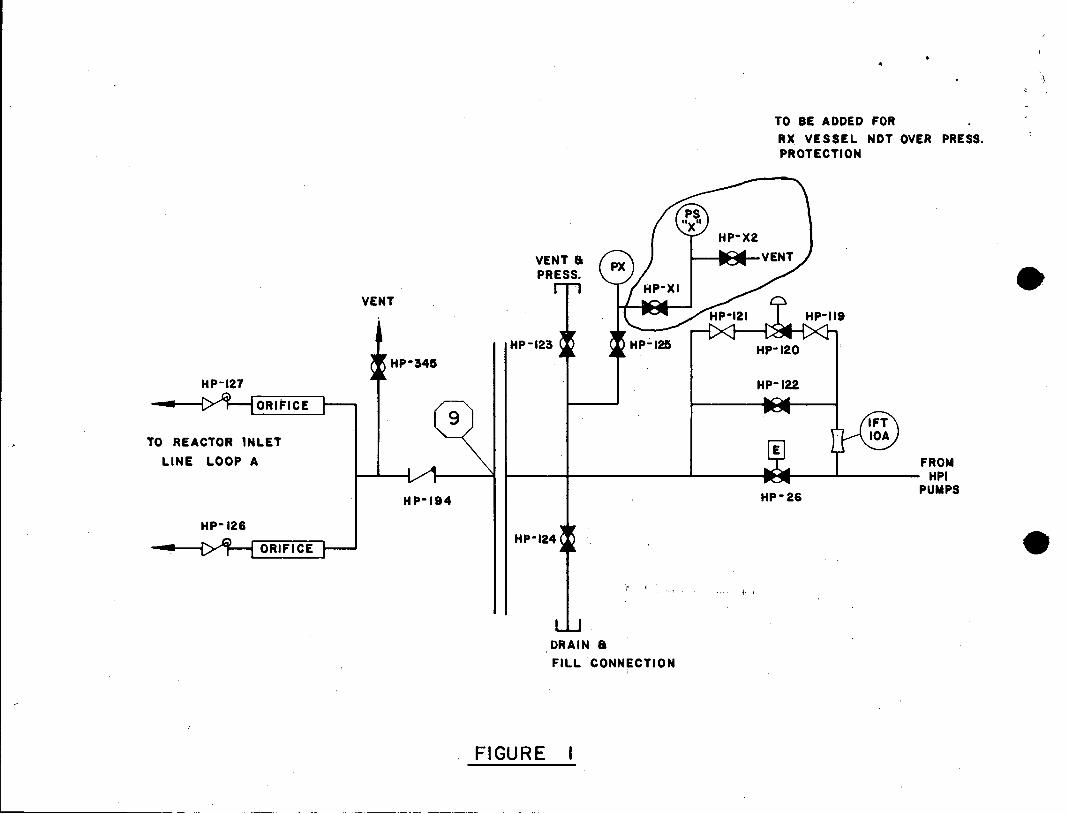
This design concept includes an alarm which activates upon reaching an RCS temperature above Minimum Pressurization Temperature (MPT) to alert the operator to activate the overpressure protection system. This alarm monitors reactor coolant system temperature. Once this system is activated, a pressure switch, located on the HPI system as shown on attached Figure 1, senses RCS pressure. If RCS pressure exceeds the limiting value of approximately 500 psi, the pressure switch closes to energize a relay which trips the breakers to the HPI pumps.
The overpressure protection system is activated by valving into service the pressure switch and operating an electrical key-lock switch (S45/lVB2) in the control room. The pressure switch is valved out during normal operation abot MPT to prevent generation of the electrical signal indicating a high pressure condition. Both the pressure switch contact and the key-lock switch contact are required to energize the lock-out relay (lLOR/lVB2). During normal operation a fault in either the pressure switch or the key-lock switch will not cause the lock-out relay to be energized. Additionally, energizing the lock-out relay will not in itself cause a trip of the HPI pump breakers. The key-lock switch contact and the lock-out relay contact in the HPI pump breaker trip circuit must both be closed in order to trip the HPI pump by this means. Other trip features are not affected.
The following is a description of the series of events that would occur during a cooldown with this system installed:
Initial conditions: Normal cooldown in progress; HPI pump in operation to provide RCP seal water and RCS makeup water.
1. At a specific temperature above MPT, a warning alarm is energized. This statalarm monitors RCS temperature from a indicator located in the control room (See drawings OEE-118-31, -32).
2. After the alerting statalarm is energized and as directed by the station .procedure for cooldown, the control operator activates the overpressure protection system. The HPI isolation valve, HP-26, is verified shut, its breaker racked out and tagged as required by the procedure. The overpressure protection system is activated by valving into service the pressure switch (See design Figure 1) and operating the key-lock switch. The
overpressure protection system is now aligned for operation. As normal
cooldown continues, if the setpoint of the pressure switch is not exceeded, a normal cold shutdown condition is achieved without further overpressure protection system actions.
-2
3. However, if the setpoint of the pressure switch is exceeded, a pair of contacts in the circuit to the lock-out relay (lLOR/lVB2) are closed. See Elementary Diagram, H. P. Injection System, Overpressure Trip, OEEXXX. Contacts S34/1VB2 2a, 2b had been previously closed by operation of the key-lock switch. Thus, lock-out relay, lLOR/lVB2, is energized causing contacts in the trip circuit of each HPI pump breaker to close. See drawings OEE-117-47, -76, -62.
In this trip circuit, contacts from both the lock-out relay and the key-lock switch are required to energize the trip coil. (Contacts lLOR/1VB2 lF, lFa and S45/1VB2 4a, 4b for HPI pump 1A; lLOR/1VB2 2F, 2Fa and S45/1VB2 6a, 6b for IB; lLOR/lVB2 3F, 3Fa and S45/lVB2 8a, 8b for IC).
4. When RCS pressure has been reduced below its reset value, the control operator must manually reset the lock-out relay. Upon doing this, the HPI pumps may be re-started.
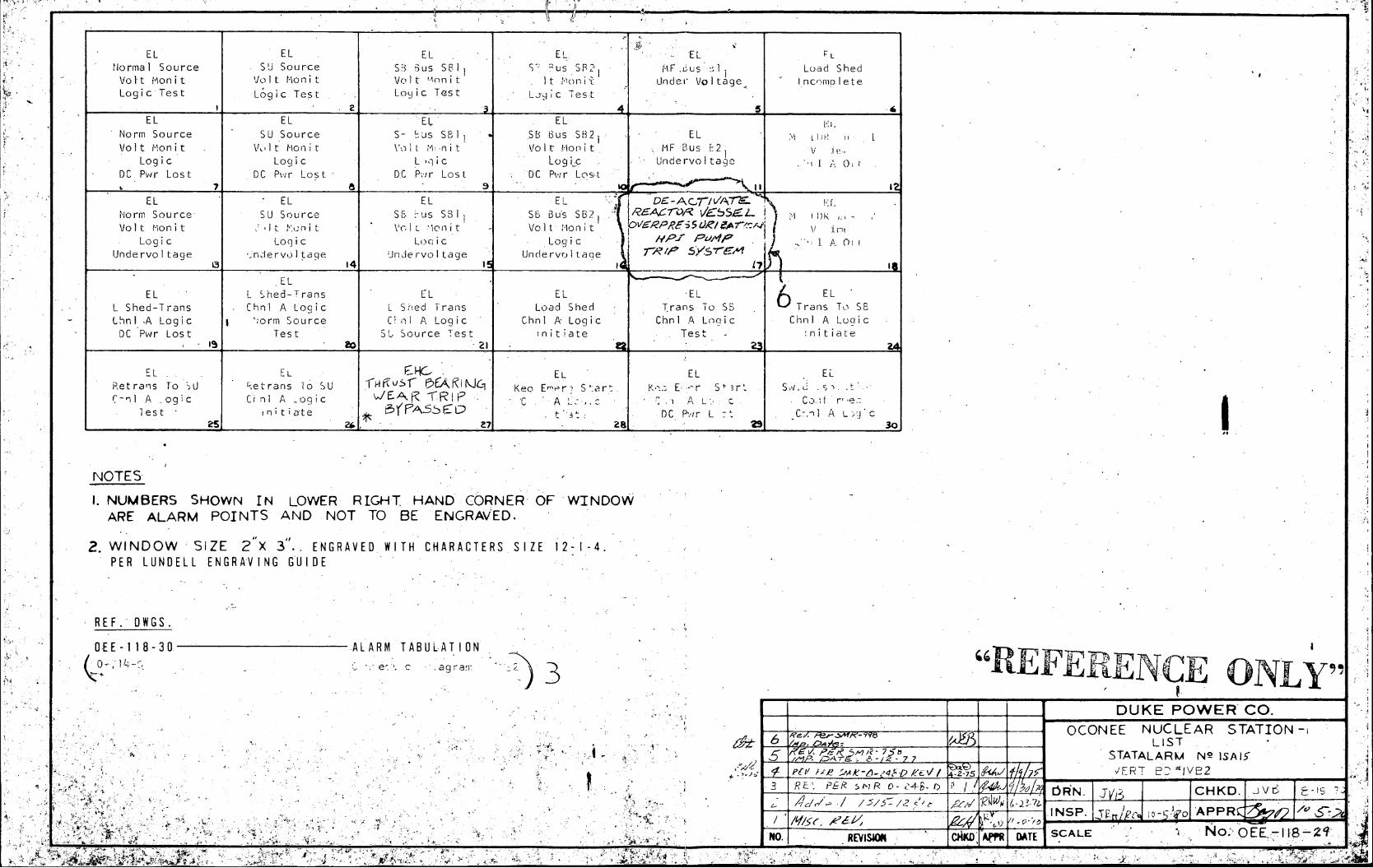
5. When a heatup from cold shutdown commences, the overpressure protection system remains in operation until the deactivate alarm is energized. This statalarm monitors RCS temperature and energizes at a specific temperature above MPT. Please see drawings OEE-118-29, -30. When directed by the station procedure for heatup, the control operator will deactivate the overpressure protection system by valving out of service the pressure switch and de-energizing the key-lock switch.
Elementary drawings have been provided for Unit 1 systems only; a similar design could be utilized for Unit 2 and Unit 3.
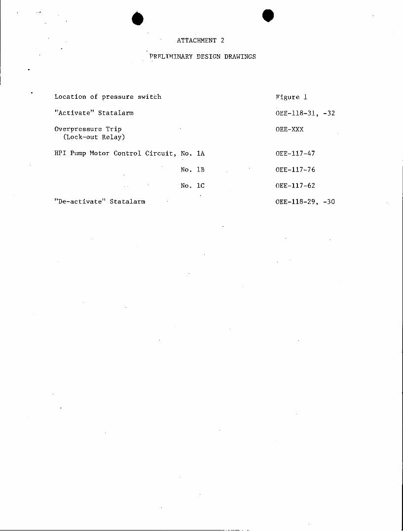
ATTACHMENT 2
PRELIMINARY DESIGN DRAWINGS
Location of pressure switch Figure 1
"Activate" Statalarm OEE-118-31, -32
Overpressure Trip OEE-XXX (Lock-out Relay)
HPI Pump Motor Control Circuit, No. 1A OEE-117-47
No. lB OEE-117-76
No. lC OEE-117-62
"De-activate" Statalarm OEE-118-29, -30
TO BE ADDED FOR
RX VESSEL NDT OVER PRESS. PROTECTION
HP-X2
VENT & X VENT
PRESS. HP-XI
VENT
HP-123 HP-125 HP- 120 HP-345
HP-127 HP-122
9 IFT
TO REACTOR INLET 10A
LINE LOOP A FROM HPI
HP-194 HP-26 PUMPS
HP- 126 HP-124
DRAIN & FILL CONNECTION
FIGURE I
A6/7 VA7T
FWP A FWP A FWP B FWP 8 IObVPR5554-M"/iAr
FLOW. FLOW FLOW FLOW Cc". S TP pP LOld LOW LOl LOw 10 LO COTR2OLP . 2T/ Sr'Sni
EL EL EL EL EL EL CT4 SB 3us 1 C,4 St Bus 2 C! 5 Sh Sus 1 C-5 SE .us 4 XV Rdr Bkr 4 KV Fdr Bi<r
Bkr .kr 3kr ek S22 Closed Closed Closed Closed C 2os d Closed
a WCledt
G CW EL EL E L EuL 212nter~in Waste nterimTaste
C-4 PuS 1 Ci ius 2 C75 3us 1 C25 bus 2. Gas Decay Tank Gas Decay Tank Auto ran:; Auto :rans Auto rans Auto Trans .C-Press. .Ji- ID-Press. Hi
'block Mlock Block block
14'
EL EL EL. EL
13.8 KV Fdr 100 KV Fdr 4 KV Fdr Bkr4 KV Fd Bkr
Deenerg i zed Deenergized SI S2 Clos d Clos d
23 14
RC RC RC. RC Decay heat Deza' Heat
RCP t RCP 1'.2 RCP 1 Bi RCP IB2 Cooler U Cooler I B
0 LL'FT RJMP 0 L iFT PUMP OL L FT PUMP 041 LFT PUMP itow Hg Fow g"
I. NUMBERS SHOWN IN LOWER RIGHT HAND CORNER OF WINDOW ARE ALARM POINTS AND NOT TO BE ENGRAWED.
2. WINDOW SIZE 2 X 3" ENGRAVED WITH CHARACTER pIZE 12-1-4 .VER LUNDELL ENGRAVING GUIDE
3_. *-liidicates, cont.-ict op, n. in slarrn coneiti.n.. -~.i
*E N
REF. DWGS./ Der D.
OEE-118-32 ALARM TABULATION / e K0O-714 -Q conNNcn1 o:AGRAM - IVS2 L R.t o 7
.ADOD t/NDOW7 -W 0-197, AOA4k' a) )
9 Fc- Ao a DUKE POWER CO 7. 4ived kt,'Jo/'s S el C d4//s .J a 1.1;,3 OCONEE NUCLEAR STATI d 6 A' 4-/65£ 9/2f LIST 5 te ,x/ -9 IXAl 7 STATALARM No ISA1 5a 5e R, 1,7V8
EL EL EL EL EL Normal Source SU Source S3 !us SB I us SMF .ius 11 Load Shed Volt Monit Volt Monit Volt 1onit It .Monii Under Voltage Incomplete Logic Test Logic Test Loyic Test Ljyic Test
EL EL EL EL Norm Source SU Source S- %us SBI1 Volt Monit Volt Monit Volt M nit VoIt -olit MF Bus E2
Logic Logic L q i c Log c Undervoltage 1 0 DC Pwr Lost DC Pwr Lost DC Rr Lost DC Pwr Lost
EL EL EL D L Norm Source SU Source SE i-us SB1 Sb Bus SB21 I o V/ssE
V Ppt Volt Mion it -It ln i t VolL Ion it - Volt Mon it E i Logic Loqic LIic Logic HP- P
Undervoltage ndervol tage Undervol tage Undervoltaqe 13 14 .15__
EL EL L Thed-Trans EL 6 EL
L Shed-Trans Chnl A Logic L Shed Trans Load Shed Trans To SS Trans To SE thnI A Logic 1 'orm Source C~nl A Logic Chnl A Logic Chnl A Logic Chn A Loic DC Pwr Lost Test SL Source Test init iate . Test -nitiate
- I 8 223 24
EL L EL EL EL Retrans To -AU Retrans To SU 1 Keo Emri S-ar' K E .- r Sh-rt S,- /, .t
7-n) A ogic Clnl A cogic IE C A . .1 A L . Co.I r'e: lest initiate t a DC Pwqr L : Cil A LJZ
NOTES
1. NUMBERS SHOWN IN LOWER RIGHT HAND CORNER OF WINDOW ARE ALARM POINTS AND NOT TO BE ENGRAVED.
2. WINDOW SIZE 2"X 3".. ENGRAVED WITH CHARACTERS SIZE 12-1-4. PER LUNDELL ENGRAVING GUIDE
REF. DWGS.
OEE-118-30 ALARM TABULATION
"REFRNEOL DUKE POWER CO.
___-eOCONEE NUCLEAR STATIONu__ _-_ OA LIST
7 7 STATALARM N2 ISAlf
p ~,-; fPCI bc ~..'~.p~V 7-s 'ERT E VB2 * 3 RE , ORN. 51 R CHKD
/ / _______________ INSP. ? / o- o APPR
RYSMO -MK Af"R SCALE N.OEiS2
AL.ARM ACTUATOR TAG LOCATION. OF ACT UATOR
/ .SOU' F t/// -FVOLT. TELT PELA'YS R7NA 6,c -*V'C. PR'/. SW. PNL /EPLPI
2 su ." RTEA, R,
3 sS/, vA1DEqiovo. Tr1 r.. AT la py EP ks. Pw R. zW. P "I7psLWP
4 A " '' GeC I,
5 MAIN FbR I4/5 / UNDR1VOLTAGE AV/* RLZAY 278/Ix EMIERSG PR. SW. P/IVL, 4/PSLP/