1 AP rH i> CO O <S Research and Development Technical Report ECOM-2986 PCM CABLE ASSEMBLY CX-11230< )/G FOR THE ARMY AREA COMMUNICATION SYSTEM by Morton Pomerantz July 1968 p r OCT2 1---53 . j mr -nibu u G/ lif DISTRIBUTION STATEMENT (1) T k l t rfocumwt hot b««n approved for public rel«a*e and salt; If* distri wfion is unlimited* UNITED STATES ARMY ELECTRONICS COMMAND * FORT MONMOUTH, N.J. Reproduced by the CLEARINGHOUSE for Federal Scientific & Technical Information Springfield Va. 22151 A
Transcript
1 AP
rH
i > CO O <S
Research and Development Technical Report
ECOM-2986
PCM CABLE ASSEMBLY CX-11230< )/G FOR THE ARMY AREA COMMUNICATION SYSTEM
by
Morton Pomerantz
July 1968
p r
OCT2 1---53 . j mr -nibu u
G / l i f
DISTRIBUTION STATEMENT (1)
Tk l t rfocumwt hot b««n approved for public rel«a*e and salt; I f * distri wfion is unlimited*
UNITED STATES ARMY ELECTRONICS COMMAND * FORT MONMOUTH, N.J.
Reproduced by the C L E A R I N G H O U S E
for Federal Scientific & Technical Information Springfield Va. 22151 A
■• - A* rj i: ■, • ■^%'-
. ^1
•A-
\ ' 1
BLANK PAGE
..££' m
r «CESSION tit
■K uoff mmmto
• .Irr
oi^mtnofcmiusiuTY CODES Blif- j «Mil. ird or ICKMI
NOTICES
Discid«««
Tk« fladiifi !■ tkia rvport ar« not to b« oomttrwd •■ u offloiftl DaptrtoMat of tk« Amy position, »!•■• so dMig» «•tod by otkor •■thorittd doonmMts.
TIM oitatioa of tndo BMM ud BMBW of BMBteotanra in tkia raporft la BO( to ba eoaatraad «a offldal Oovaramaat iadocsasMBt or «pprovtl of oonmaroisl prodoota or aanrioaa nhtmmi karaia.
OlapaalHan
Daalroy Oda raport wkaa it ia BO 1 ratafa It to tka origiaator.
oagar naadad. Do not
Report» Control Styribol OSD-1366
TECHNICAL REPORT ECOM-2986
PCM CABLE ASSEMBLY CX-11230( )/G FOR THE ARMY AREA COMMUNICATION SYSTEM
by
Morton Pom« rants
Electronic Parts and Materials Division Electronic Components Laboratory
July 1968
DA Task 1H6 40306 D487 06
This document has been approved for public release and ■ale; its distribution is unlimited.
U. S. ARMY ELECTRONICS COMMAND, FORT MONMOUTH, N. J.
* ■
■
ABSTRACT
Cabl« Atumbly CX-11230( )/G has b«en d«v«lop«d with b«tt«r •hialding. higlMr «treagth, and low«r wtight than CX-4245/C Cabla Aaaambly, for ua« with PCM Multiplax Sat« AN/TCC-44 through 46. Tha cabla aaaambUas provida 12, 24, and 48-chanaal cabla liaka in tha Army Araa Communication Syatam (AACOMS) up to 40 milas batwaan mnltiplax tarminala with unattandad rapaatars avory mila. Tha cabla ia vary ruggad for both ground and aarial inttallatioaa, Tha complata davalopmant cycla is tracad from incaption through firat production contract award.
ii
mmmmmmmm*
CONTENTS
iii
Pag«
BACKGROUND 1
CX-U230( )/G DESIGN CONSIDERATIONS 2
CABLE DESIGN 3
CONNECTOR DESIGN 5
EVALUATION OF CX-11230( )/G 7
SUMMARY OF CX-11230( )/G EVALUATION 10
INTEGRATED ENGINEERING/SERVICE TESTS (ET/ST) 10
CONCLUSIONS 11
ACKNOWLEDGMENTS 12
REFERENCES 13
TABLES
I Development Objectives of CX-11230( )/C 14 II Comparative Design Data 15 III Shielding of PCM Cable Conttructions Per Fig. 5 16 IV Framing Teats on CX-11230( )/G Prototype 17 V Radiation from CX-11230( )/G (GRC-26
Operating at 2. 304 MHs) 18 VI Summary of Contractor's Test Results -
CX-11230( )/G 19 VII ET/ST Results 20 Vm Comparison of PCM Cable Characteristics 22
jiiiiiwr' —■■-——
• '•■*«"*'■■-T- ■mriim ■ in a rnnrTTTrrriTWMWHIMBMMIIIMilWlWOTBfHIiri
FIGURES PM[»
R Typical PCM SytUm 23 2 Attenuation M a Function of Froquoncy 24 3 Charactoriatic Imp«danc« as a Function of
Froquoncy 25 4 Constructional Comparison of PCM Cabls
Asssmblist 26 5 Cabls Constructions for Sbislding ETsluation 27 6 Co^asctor Cross-ssction 28 7 Schomstic of Transmission Si Shiolding Tsst
Cable Assembly CX-11230( )/G has been developed to replace CX-4245( )/G in Pulse Code Modulation (PCM) systems because of unsatis- factory test results on CX-4245( )/G during service tests. These cable assemblies provide 12. 24 and 48 channel cable links between PCM multi- plex terminals of AN/TCC-44 through 46 and/or between the multiplex terminals and radio relay terminals employed in the Army Area Communica- tion System (AACOMS).
In April 1957, the CX-4245( )/G was originally intended for a 24- channel frequency division multiplex (FDM) system with a capability for dispensing a continuous length of ten miles from aircraft. Inasmuch as the Army aircraft in use at that time had a maximum load capacity of 3,000 pounds, the weight of the cable was established at 200 pounds per mile (allowing 1,000 pounds for the weight of the packaging and dispensing equip- ment). During the course of the CX-4245( )/G development, the require- ment was changed from 24 FDM channels to 48 PCM channels. Fortunately, the CX-4245( )/G had the necessary electrical characteristics to satisfy the new PCM transmission requirements. Engineering tents by the contractor and USAECOM confirmed the soundness of the electrical design of the cable assemblies and the dispensing equipment to airlay ten miles of C>.-4245()/G in a continuous length with no damage. 1'z However, service test« con- ducted by USATECOM at Fort Huachuca in 1964 disclosed that the CX-4245( )/G was unsatisfactory for ground dispensing from reels mounted on trucks, and was inadequately shielded. 3'4 In order to stay within the 200-pound per mile weight limitation imposed by the airlay requirement, the cable lacked the necessary tensile strength to withstand the abuse associated with aerial (pole) installation and ground reeling equipment which apparently was more severe than the abuse from air dispensing equipment. Failures occurred both in the cable itself and at the cable-to-connector junction. The shielding inadequacy, likewise, reunited from the weight limitation imposed by the airlay requirement. The cable proved to be susceptible to interference from external RF sources resulting in loss of PCM transmission, and was itself a source of interference with nearby communications equipment when it was energized by the PCM signal. In addition to these major deficiencies, difficulties were experienced with the connectors, puch as fragile pin contacts, fouling of coupling threads, and deep recessed inserts which were difficult to clean.
The failure of the CX-4245( )/G in service test necessitated the dev- elopment of a new cable assembly (nomenclatured CX-il230{ )/C), which
•
I
would satitfy the «lectrical trans mil ■ ion requirements of the tactical PCM communication eyetem with improved cable and connector ruggedneee, and shielding. At the same time» these characteristics were to be optimised with respect to weight and flexibility of the cable, recognising that some relaxation of the airlay requirement would probably be necessary due'to the anticipated increaee in weight over that of CX-4245( )/G. Inasmuch as the primary use of the cable would be with ground payout equipment, this eacrifice in airlay capability was considered well justified. (The airlay requirement was eventually deleted.)
Since CX-n230( )/G could not be developed and put into production in time to meet the delivery commitments of the initial production of PCM equipments, the Army authorised a limited (one-time) procurement of CX-4245/G. a modified version of the CX-4245( )/C. The modification consisted of the original cabls with an additional overall copper shield braid, a high density polyethylene jacket, and improvement of the existing connectors. The modified cable had satisfactory shielding and physical ruggedneee but wae prohibitively heavy and stiff for ground handling.5 In addition, the connectors wore not shielded and had low retention to the cable. Provisions were made to strain relief the connectors, and to electrically connect thr cable shield at sach 1/4 mile as field expedients, and thereby permit the use of CX-4245/G despite its other defieiencieo. Effort wae then expedited to develop thr new cable assembly with objectives noted in Table I.
CX-11230( )/G DESIGN CONSIDERATIONS
The PCM Syetem
When considering a new cable assembly deeign, it is well to have soms understanding of the system in which it is to be need. A typical PCM system ie shown diagrammatically in Fig. 1. The signals enter the multi- plex equipment where they are samplsd and converted into a six-digit binary code, and transmitted, either by radio relay or dual coaxial cable, to the other terminal where they are decoded and reetored to their original intelligence. The terminal equipment-at both ends Is identical, thua making possible the two-way communication. A dual coaxial, rather than single coaxial cable^is used to eliminate directional filters from the unattended repeaters, thus greatly simplifying their deeign and reducing their else, weight, and cost..
Transmission Properties versus Physical Requirements
It is seen, in Fig. 1, that unattended cable repeaters are spaced at one-mile intervals. The PCM signal at the cable input is approximately a
■■Bbui^*-
•
• i
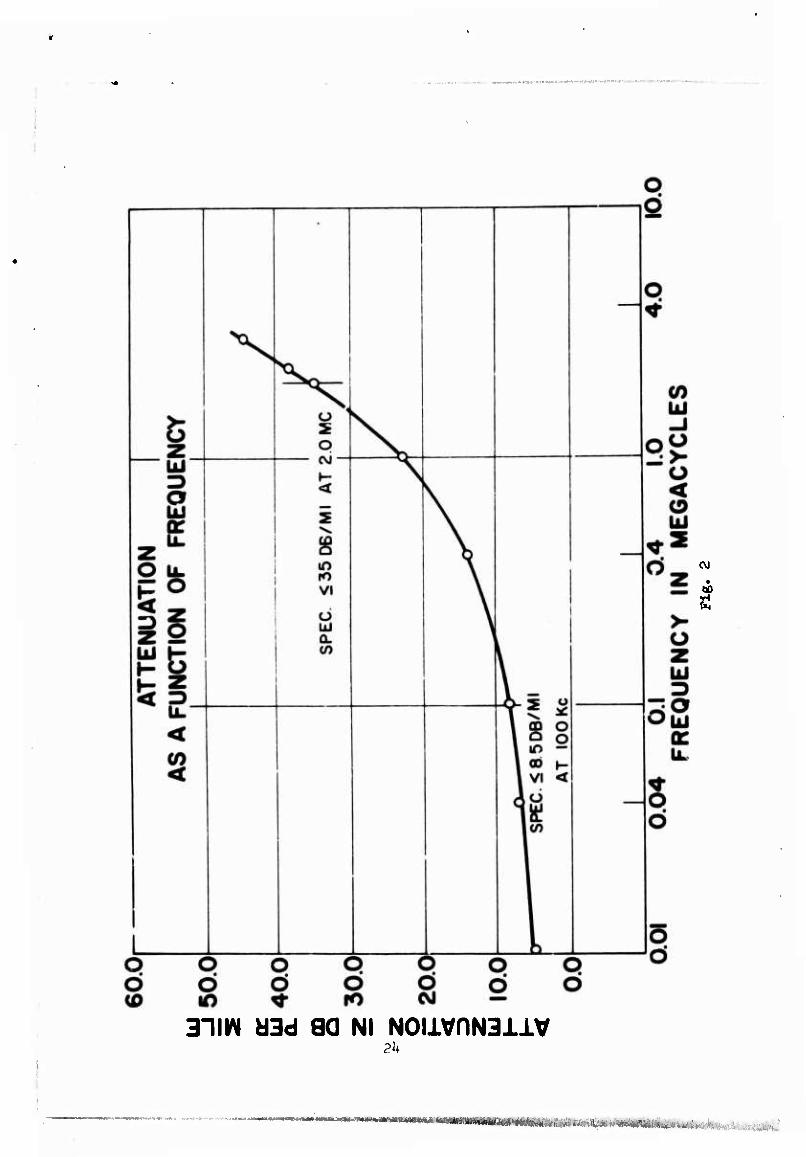
■quare wave pulse of 2.5 volts peak-to-peak magnitude. Because of the cable attenuation, the signal appears, at the unattended repeater input, dis- torted in shape and greatly diminished. In order for the repeater to restore the signal to its PCM form and shape, the signal must be no less than 30 millivolts peak-to-peak amplitude. Failure to have this 30 mV level at the repeater input can cause transmission errors or possibly, complete loss of transmission. Consequently, the attenuation of the cable at the repetition rate of the PCM pulse (2.304 MHz) was established at 38 dB/mile. In addition, for error-free transmission, the near-end crosstalk between lines waf required to be at least 67 dB below the 2. 5 volts PCM signal le /el. In a coaxial construction, this is a function of the shielding provided by the outer conductors of the coaxial lines. The impedance of the cable was established at *5 ohms for compatibility with the repeaters, PCM terminal and fault location equipment.
Essentially, the new cable must have the same transmission properties as the CX-4245/G (LP version), at the same time be much more rugged to withstand field abuse, more flexible for ease of handling in paying out without kinks and snarls for ground and aerial installations, have improved shielding, and be lighter in weight.
CABLE DESIGN
Transmission Properties
For the transmission properties (attenuation and impedance) of the cable to be the same as the CX-4245/G, it was necessary to use a partial air dielectric material (4 < 2.0) to achieve a significant weight reduction. The small size, flexibility, and ruggedness requirements eliminated all types of partial air dielectrics except a foamed low-loss material. The ultimate selection was foamed high density polypropylene because of its excellent flex life and mechanical ruggedness. The dielectric constant of this foamed material is 1.6 as compared to 2.25 for solid polyethylene. For the same size center conductor (.030") this allowed an 18% reduction in size of each coaxial cable element. The significance of this size reduction is that it considerably reduced the quantity of copper for the various braids, resulting in a 40% overall weight reduction compared to the modified CX-4245/G. The attenuation and impedance characteristics as a function of frequency are gi' en in Figs. 2 and 3.
Physical Properties
The construction of the CX-11230( )/G is compared with the CX-4245/G in Fig. 4 and Table II. It is seen that the general construction
fMyMMiiftiWftirnr"* "■"'"'''
oi both cable« is similar with the CX-11230( )/G being smaller and therefore lighter by virtue of the foamed dielectric material and less copper as pre- viously discussed.
Two other major differences account for the increase in ruggedness of the cable, namely, (1) the material of the shielding braid, and (2) the addition of the mylar tape binder, The shielding braid is made of a high tensile strength (127,000 psi) copper-clad steel conductor which also serves as a strength member. The mylar tape holds the twisted coaxial cable pair compactly as well as preventing damage to the coaxial cable jackets by the shield braid ends. The high tensile strength of the shield braid resulted in an overall breaking strength which exceeded the 650-pound objective by 50 to 100 pounds. The compact construction, the cut-through resistance of the mylar binding tape, and the high density foam polypropylene dielectric material imparted high compressive strength to withstand over 30,000 vehicle crossings without electrical malfunction.
It was derided to use medium density polyethylene instead of high density polyethylene for the overall jacket to increase the flexibility of the cable. Field tests later proved that there was very little sacrifice in ruggedness because of the lower density material, and the cable had greatly improved handling characteristics.
Shielding
Designing for adequate shielding proved to be the most difficult of tue objectives to attain. A number of factors contributed to the difficulty.
1. No specific criteria were established. Only qualitative operational requirements were stated and specified that the cable should not be suscept- ible to radiation from tactical transmitters operating in its vicinity and that it should not be a source of interference to nearby tactical receivers when PCM signals were being transmitted. The 100-foot susceptibility, and 50- foot radiation criteria were arbitrarily selected as being representative of a probable "worst-case" tactical situation. It was reasoned if the cable could provide shielding to meet these criteria, it would provide for the majority of situations.
2. There was no direct correlation between the arbitrary tactical criteria and a practical laboratory test. The variables of a field test environment were numerous, and the susceptibility from a typical tactical transmitter operating at a distance of 100 feet or compatibility with a
w— ill I IWIII i nX-tiMi., I
tactical receiver operating 50 feet from the cable could not be related quantitatively with surface transfer impedance or "dB" of shielding in a laboratory setup.
3, The degree of shielding provided is primarily a function of thick- ness of braid at the 2.304 MHz pulse repetition frequency of the PCM signal. Obviously the more shielding braid, the heavier the cable, which of course is directly contrary to the weight reduction objective.
The solution, therefore, became a matter of optimization of the shielding and weight objectives. The apparatus used for laboratory evalu- ation of various design approaches was a triaxial " shielding efficiency tester. The details of this evaluation are given in another USAECOM test report. ' The method primarily entails comparison of the relative shielding efficiency of different constructions. The constructions evaluated are shown in Fig. 5. The data are tabulated in Table III for Constructions 1 through 8. Construction 9 is the design which actually evolved from the evaluation of 1 through 8. It is seen that constructions 1, 4, and 5, all twisted pair coax- ial* with no additional shield layers, had approximately the sume (and relatively poor) shielding characteristics. Construction 8, a parallel pair with no additional shielding, had the poorest. Some improvement is noted in Constructions 6 and 7, parallel coaxial pairs, with an additional open (single-end) high strength steel braid directly in contact with the coaxial braids. Further improvement is noted in Construction Z which has the same coaxial elements as Construction 1, but with a multiple-end steel braid. The best results were obtained in Construction 3 in which a multiple-end copper braid is substituted for the steel braid of Construction 2 p^us an overall polyethylene jacket. It is noted that the two best constructions have in common a multiple-end braid which is isolated from the coaxial braids. Construction 9. the ultimate CX-11230( )/G design, was essentially based upon the design of Constructions 2 and 3. The validity of the triaxial tester method for the laboratory evaluation of the relative effectiveness of the shield designs was borne out in subsequent field tests in which one-mile prototypes of designs (6 through 9) were evaluated for conformance with the susceptibility and radiation criteria. Construction 9 was far superior to the others in the field tests.
CONNECTOR DESIGN
Inasmuch as connector deficiencies were in large measure responsible for the failure of the CX-4245( )/G in service test, a considerable part of the development effort in the CX-11230( )/C program was devoted to the connector design. Early in the program, the following design guidelines were established:
' ,■' ■
!
1. A single connector with two coaxial contacts instead of two individual coaxial connectors. The advantages to be gained were:
a. Convenience of coupling only one connector instead of two.
b. Vastly improved clamping to the cable strength member rather than relying on the low tensile strength copper outer conductors.
c. Improved shielding because the shield braid is terminated in the connector body, thus providing continuity of the shield braid from terminal to terminal of the PCM equipment. In the CX-4245/G. the shield braia was necessarily terminated two feet from the connectors.
2. Hermaphroditic mating so that either end of the cable assembly can be started on the reel.
3. A coupling device for quick-disconnect, ruggedness, foul-proof- ness, and which is easily cleanable.
4. Coaxial contact elements resistant to damage, and corrosion with positive engagement.
5. Waterproofness in both the mated and unmated conditions.
6. No special tools to assemble connector to cable.
A cross-sectional view of the connector is shown in Fig. 6. The two individual coaxial contacts are contained within the main insulator, a molded polysulfone material. This entire insert is housed in a cadmium-plated aluminum body. Complete isolation of the coaxial contacts from each other and from the aluminum body is maintained. Clamping to the braids of the individual coaxial cables as well as to the shield braid is accomplished by a wedge principle utilizing tapered ferrules underneath the braids and corresponding tapered sleeves on top of the braids. In addition to providing secure mechanical clamping, good electrical contact is achieved, thereby providing optimum shielding for the cable system.
Hermaphroditic mating is accomplished by appropriate keying of the contacts, main insulator, shell, and by a ramp lock coupling device. The coupling device provides for complete mating in less than 1/4-revolution and is virtually impervious to damage, fouling, and dirt accumulation.
The large mating surfaces and shallow recess of the inserts are conducive to easy cleaning to wipe away moisture and dirt accumulation. The contacts are short and rugged but with sufficient wiping action and silver plating for good electrical contact.
Waterproofing at the mating end is provided by means of strategically located O-rings and compression gaskets. At the back-end, sealing is accomplished by means of a molded silicone rubber boot.
Although the cable assembly procedure (Appendix A) appears complex at the initial confrontation, it is in reality quite simple after the first two or three assemblies have been made. Only two cable trimming dimensions must be measured, while the remaining cuts are made as succeeding piece- parts are assembled. This offers not only a simpler assembly procedure, but provides better reliability for the assembly than the previous metaod.
EVALUATION CF THE CX-11230( )/G
Prior to finalizing the design, two half-mile lengths of CX-11230( )/C assemblies were subjected to field tests at Fort Monmouth to evaluate the electrical transmission properties with the PCM equipment, the shielding effectiveness in terms of proximity with a high power tactical radio set, and the mechanical handling characteristics in terms of ground payouts and takeups from trucks and aerial (pole line) installations. The design evalu- ation also included the contractor's (ITT Federal Laboratories) data on the primary electrical (attenuation, impedance, and crosstalk), mechanical, and environmental characteristics. It was the purpose of the evaluation to determine what design modifications, if any, should be made in either the cable or connector prior to release for fabrication of the 50-mile quantity for ET/ST at U.S. Army Electronic Proving Ground, Fort Huachuca, Arizona.
Transmission and Shielding
The basic configuration for the field tests consisted of two half-mile CX-11230( )/G cable assemblies, mated at the half-mile point, and installed on a pole-line. The terminal ends were connected to AN/TCC-46 PCM equipments which were housed in shelters one mile apart. (See Fig. 74 PCM transmission, both with and without a TD-206 Pulse Restorer, was satisfactory and two-way voice communication on the order wire was established with no difficulty. The shielding efficiency of the r:x-11230( )/C was evaluated from two considerations, namely, (1) susceptibility to pickup of electromagnetic radiation from nearby transmitters, and (2) radiation
from the cable which could interfere with nearby tactical receivers. The •ufceptibili.y criterion wa« the ability to operate Radio Set AN/GRC-26, trammitting at full power as cloae as 100 feet from the cable without causing "loss of frame" of the PCM terminal equipment. The criterion for radiation from the cable was no pickup of the PCM signal greater than 3 dB above ambient noise by NM-20B RI-FI meter at a distance as close as 50 feet from the cable. Provisions were made in the setup to allow evaluation of the effects of various shielding and grounding configurations. Fig. 8 illustrates the wire-form shorting clips used for mutual shorting of the coaxial braids, and shield braid, and the connector housing. Thi*; provided valuable information to optimize the design of the Engineering Development (EO) Models to be delivered for Service Test. Details of the tests are as follows:
a. Framing Tests (Susceptibility) - Tests were made to determine how close an AN/GRC-26, transmitting at full power, could come to the cable without causing loss of frame. Fig. 9 shows the AN/GRC-26 starting its run at PCM shelter. The test results for the seven different test con- ditions are given in Table IV. In interpreting the data, it is necessary to understand that the TD-206 Restorer was modified, for these tests, with 2-foot "pigtail" cables terminated with connectors which mate with the CX-11230( )/G. (See Fig. 10.) The "pigtail" cables were virtually un- shielded. These unshielded "pigtails", it is believed, account for the poor results obtained under Condition 3. Since, in this condition, the shield braid is shorted to the coaxial braids, the energy that is picked up on the shield braid appears directly on the coaxial braids. Consequently, the noise voltage which appears at the input terminals of the Restorer reduces the signal-to-noise ratio below the critical value for proper functioning of the Restorer, and the out-of-frame condition results. In Conditit/u 2, although the Restorer is used, the shield and coaxial braids are not shorted. Con- sequently, the noise voltage picked up on the shield braid is isolated from the coaxial braids, and the out-of-frame condition does not occur before the transmitter is in the vicinity of 100 feet from the cable. The results at Condition 1 are almost identical with those at Condition I. Under the re- maining conditions, of course, the results are excellent. The most signif- icant factor of Conditions 4 through 7 is that the shield braids are continu- ous from cable to cable. It is important, then, that the connector provide a means for preserving the continuity of the shield braid from assembly to assembly. From the data, it does not appear warranted to provide a perm- anent means for mutual shorting of the shield and coaxial braids. Although the data shows some improvement with the braids shorted, other situations may arise in actual field service where it would be more beneficial for the
8
«WM* iw * dtnflui
braids to be isolated. With a permanent short in the connector, this could not be done. Furthermore, it would be more costly to provide this "short- ing" feature. Consequently, a design based on Conditions 5 and 6 appears to be the preferred one. Tests were also run with the AN/GRC-26 trans- mitting full power at 4.608 MHz (the second harmonic of the PCM signal). No loss of frame occurred under these conditions with the AN/GRC-26 traveling parallel to the cable at a distance of 20 feet from the cable. Additional tests with the AN/GRC-26 transmitter slightly detuned from 2. 304 MHz disclosed significant reduction in susceptibility.
b. Radiation from the Cable - Measurements were made with a NM-20B, RI-FI meter at 2.^04 MHz, the fundamental PCM signal. (See Fig. 11.) The results are given in Table V for four different test condi- tions, all without continuity of the shield braids from cable to cable. How- ever, it is noted that the best results were obtained when the shield and coaxial braids are shorted. In effect, the shield is actually carried through from cable to cable which is believed to account for the superior results. Since the shields would be continuous in the final design of the ED Models, similar results were anticipated in the ET/ST.
Handling and Ruggedness
The models successfully withstood 20 cycles of pole-line installations, performed as described in Ref. 8, and 10 cycles of payout from a moving vehicle over various terrains. The pole-line installation cycle consisted of payout from the moving vehicle, installatioa on the pole-line dt a height of 20 feet with sags of 18" to 36" on spans ranging from 125* to 178', removal from the pole-line, and recovery onto the reel. The vehicle payouts were conducted on a macadam road with the vehicle traveling between 5 and 10 miles per hour, a dirt road with many bumps and depressions, and a heavily vegetated field with many bumps and depressions. On the latter two terrains, the speed of the vehicle was adjusted to the condition of the ter- rain. One vehicle payout cycle consisted of paying out and recovering the cable assembly. Six of the ten cycles were conducted on one half-mile assembly; the remaining four cycles were conducted on the two one-half mile assemblies with the connectors mated at the midpoint. In the payout, the mated connectors were allowed to fall off the reel to the ground at random. After each pole-line installation and vehicle payout cycle the assembly was checked for DC resistance of the conductors, short-circuiting of the conductors, insulation resistance, visible physical damage to the cables and/or connectors, and connector uncoupling. The models remained satisfactory throughout all the cycling. Three times during this cycling and
mmKki.inm
at the conclusion of the cycling, the models were installed on the pole-line at the PCM shelter site, and the transmission properties were checked. Both PCM transmission and order wire voice communication were unim- paired. The reaction of the line crew to the handling of the cable was generally favorable. Payout from the vehicle and installation on the pole- lines presented no problems. Preformed Line Products ND-517 and ND-519 dead-end cable grips were used for the pole-line installation (Fig. 12). However, the half-mile of cable on the reel was judged to be too heavy for two average men to handle conveniently. In addition, the cable is too large in diameter to be accommodated in a half-mile length on a OR-15B or a DR-5 reel.
Contractor's Data
The contractor's (ITT) test results are summarized in Table VI. These tests were performed at the contractor's plant to determine compli- ance of the cable with Electronics Command Technical Requirement SCL- 7792A. The test results indicate this compliance. In addition, cable specimens were subjected to 20,000 vehicle (mostly passenger cars) cross- ings on a macadam road. No physical damage or degradation of electrical properties resulted.
SUMMARY OF CX-11230( )/G EVALUATION
As a result of this evaluation, the contractor was authorized to proceed with the fabrication of CX-11230( )/G ET/ST Models. The transmission and shielding properties were within the prescribed acceptable limits. The shielding is optimized by maintaining electrical continuity of the shield braid from shelter to shelter. Provision was made in the connector design for a conductive path for the shield braid through the connectors. Similar provi- sion will be made in the TD-206 Pulse Restorer.
INTEGRATED ENGINEERING/SERVICE TESTS (ET/ST)
Fifty miles of CX-11230( )/G were fabricated for ET/ST at U.S. Army Electronics Proving Ground, Fort Huachuca, Arizona. The optimized cable and connector design features, as determined in the foregoing design evaluation, were inccrporated. The testing was conducted from January to October 1967 ' in two portions, namely. Engineering Test (ET) and Service Test (ST). The "ET" portion of the test was conducted to determine the technical performance, engineering adequacy, and safety characteristics of the test item. The "ST" portion was conducted under simulated or actual
10
■ '
field conditions to determine the performance capability of the test item, its associated tools and test equipment, and the suitability of the CX-11230( )/G and its maintenance package for use by the Army. The test results are summarized in Table VII.
The only areas of difficulty experienced during the ET/ST were associated with the connectors. A number of models failed the 3,000 volts DC dielectric strength applied for one minute across the inner and outer contacts of each coaxial line. Some evidence of water leakage was dis- closed during the Immersion, Outdoor Weathering, and Human Factors tests. The voltage deficiency and the water leakage shortcomings are con- sidered easily correctable and appropriate measures have already been incorporated in the procurement data. Although some water leakage was detected under the cable sealing boot by means of a fluorescein dye and ultra-violet light, it should be noted that exposure of two miles of CX-11230( )/G to the Moisture Resistance cycling of MIL-STD-202 for two months caused no electrical malfunction of the PCM equipment. The volt- age breakdowns were traced to two causes, namely: (1) improper cable assembly procedure; and (2) cracked polysulfone insulators. The cable stripping dimensions established by the contractor for the cable assembly procedure are considered impractical because of the tight tolerances. Accordingly, improper assembly resulted and contributed to the voltage breakdowns experienced during ET/ST. Furthermore, too much slack was allowed in the coaxial lines which resulted in severe "looping", displace- ment, and air voids in critical areas. The solution was a revised, simplified assembly procedure (Appendix A) which all but eliminates pre- stripping of the cable. The new assembly procedure requires each cable element to be stripped flush with its associated connector piece-part as it is installed on the cable. This approach eliminates guess-work and uneven cuts, thereby minimizing internal voids which are the primary cause of voltage breakdowns. Fig. 13 is an exploded view of the connector parts as they are assembled to the cable. The problem of the cracked polysulfone insulators was solved by devising an annealing process which relieves internal molding stresses which cause the cracking.
CONCLUSIONS
The development of the CX-11230( )/G was completed with the con- clusion of the Integrated Engineering/Service Tests. The CX-11230( )/G met or exceeded all of its development objectives and is significantly superior to CX-4245/G. Effort is currently underway to establish CX-11230( )/G as a Standard A item for Army use, and initial production
11
contract for 1/4-mile assemblies with associated adapters has been awarded with initial delivery anticipated for mid-1969.
The accomplishments in terms of the major characteristics are sum- marized in Table VIII where the CX-11230{ )/G is compared with the orig- inal CX-4245( )/G (ET/ST - 1963), the interim CX-4245/G (LP - 1965), and inevitably with Spiral-4. Comparison with the Spiral-4 is made because that cable is used in the cable system of the equipment which is being re- placed by the PCM equipment. It is noted that the CX-11230( )/G compares quite favorably with the Spiral-4 as far as ruggedness is concerned and is considerably lighter in weight. A quad construction such as the Spiral-4 was ruled out because the required transmission properties in a quad would result in a cable weighing over 520 pounds per mile and having a diameter in excess of .428 iuch, both considerably higher than the program objectives.
Various accessories were developed to integrate the CX-11230( )/G into the PCM equipment. Bulkhead receptacle, UG-1837( )/U will be used on the shelters which house the PCM equipment,on the pulse restorers, and on Transmission Test Set AN/PTM-7. Cable Assembly CX-10734( )/G is an adapter cable to provide the interface between systems which use both CX-4245/G and CX-11230{ )/G terminations.
ACKNOWLEDGMENTS
The author wishes to express his appreciation to the Communications/ AOP Laboratory of this command for making available personnel and equip- ment at various stages throughout the development program. Particular thanks is expressed to Messrs. James Salton, Robert Alzner, Peter LaMarca, and Frank Evichin for their valuable technical guidance regarding the operation of th*» PCM equipment during the field testing both at Fort Monmouth and at Fort Huachuca. In addition, Mr. William E. Mayo, T. F. Scoville, and Jack Spergel of the Electronic Components Laboratory, and Mr. Frank Rogers and his line crew (Engineering Support Services Depart- ment) made significant contributions in participating in the field and labora- tory tests.
12
REFERENCES
1. 4th anf" 5th Quarterly Reports, Contract DA36-039 SC-73202, "Cable and Airlay Equipment for Combat Inter-Area Communications System, " by I. T. Stoneback, C. A. Emmerich, J. H. Gesell, and W. C. Murray.
2. "An Air-Layable Carrier Frequency Cable for Mobile Warfare," by W. C. Murray and F. W. Wills, presented at 7th Annual Wire and Cable Symposium.
3. USATECOM Report No. ETA 127, "Integrated Engineering/Service Test of Cable Assembly, Special Purpose, Electrical. CX-4245( )/G, " by SP/5 Brian E. Kuehn, dated October 1963.
4. USATECOM Report No. ETA-FR-161, "Radio Interference Test of Cable Assembly, Special Purpose, Electrical, CX-4245( )/G, " by E. V. Rivera and Pfc. C. H. Mattingly, dated March 1964.
5. USATECOM Report No. FR-201, "Report of Test of Check Test of Cable Assembly, Special Purpose, Electrical, CX-4245( )/G, " by S. E. Spittle and D. W. Wykes, dated October 1965.
6. "A Proposed Standard for Testing the Shielding Effectiveness of Coaxial Cables and Shielding Materials," by J. A. Allen, Proceedings of 6th Conference on Radio Interference, October I960.
7. Technical Report ECOM-2788, AD 647217, "Shielding Effectiveness of PCM Cable System (Part I)." by J. Myslinski, J. Spergel, and M. Pomerantz, December 1966.
8. Technical Report ECOM-2711, AD 635094, "Aerial Installation of Cable Assembly, Special Purpose, Electrical, CX-4245( )/G, " by M. Pomerantz and F. Rogers, May 1966.
9. USATECOM Report No. FR-284, "Integrated Engineering and Service Test of Cable Assembly, Special Purpose, Electrical, CX-11230( )/G," by M. D. Arnold and J, J. Lyons, November 1967.
13
i o «/»
CQ
[5
CD
i CM
g o
>
00 O
C\J
o
p o
OS
u»
to
S u
a> «/>
E o
i
^.2
rp ^ a> CD
u
o (U c > o *- JO * "=
■2.E u» —
E o
o .t: E ^
§t IS E Ä.8 . ~ CD t Us It« 5 g s
Q£ NO'
a> 'j=
a>
■?5 o _
uu < j2
a>
a. 2
ö CO a>
a>
ssdu
ng
th
a> u
a) a> c c fc- «n it? uo
2 »- c c a» a> o ■S ** • «■s
75 H_ ISi 3 O JO
¥ w ^ W
c ~ o
S" CD
on LL.
a> 15 S"
"O to c
C\J
1 E 'O
"O
'ü; C
a> 03 to U l_ o o i "2 c (TJ c x: O oÖ
a> > «O «<0 CD U
Ö m
lit
'wvmmp twMr^rimuv^tri
TABLE II
COMPARATIVE DESIGN DATA
Center Conductor
Primary Insulation
Outer Conductor
Jacket
Twist
Binder
Shield Braid
Overall Jacket
CX-4245/G
#22 AWC (7/.010") - .030" annealed bare copper wire
Solid polyethylene - .108"
#36 AWC, Copper Alloy 85 - .138"
Hi-D polyethylene - . 170"
6" Right-hand lay
None
#30 AWC - .400" (major diameter) copper
1 Hi-D polyethylene- (major diameter)
.440'
CX-11230( )/G
#22 AWG (7/.010") - .030" annealed bare copper wire
1. Place Identification Tag, Itrm 3, (Dwg. SM-C-434025) on cable. 2. Pass Sealing Boot, Item 1. over cable approximately 16 inches. 3. Pass Strain Relief, Item 31, over cable. 4. Pass Protective Cover Assembly, Item 28, over cable. 5. Pass the following over cable in the following order:
A. Clamp Nut, Item 3 B. Friction Bushing, Item 4 C. Support Braid Collet, Item 2 , D. Coupling Nut, Item 16 * E. Main Body Subassembly Consisting of:
in place in grooves of main body. 6. Strip outer jacket of cable per Fig. 2. When removing outer jacket of cable, care should ue tauen to ensure that the support braid is not nicked or damaged in any way. 7. Remove support braid and mylar tape of cable back to 1-9/16 inches from end of jacket (per Fig. 2). Do not comb out the braid. 8. Slide Support Braid Cone, Item 5, over the coaxial cables, and slip cone over the mylar tape and under the support braid until the end of the support braid is flush with the widest end of the taper (see Fig. 4). Use a piece of masking tape to hold cone in position. 9. Slip Tubing, Item 29, over each coaxial cable jacket. Push back until the tubing bottoms against the Supporf Braid Cone, Item 5. 10. Slip Clamp Nut Subassembly, Items 8 and 27 (see Fig. 5),over each coaxial cable jacket. Slide back until it bottoms against the tubing. 11. Remove the jacket of each coaxial cable flush with the front end of the clamp nut. Item 8, Caution: Items must be held in place (Steps 5 thru 7) during jacket removal. 12. Slip Clamp Bushings, Item 9, over each coaxial cable braid until each bottoms against the front face of clamp nut, Item 8. Trim each coaxial cable braid flush with the front end of the clamp bushing. Item 9. 13. Carefully slide Ferrules, Item 10, over each coaxial cable dielectric. Push ferrule under the braid until it bottoms, at the same time pushing clamp bushing. Item 9, forward. 14. Slip rear insulators. Item 12, over eac'i coaxial cable dielectric until each bottoms against the ferrule. Item 10. Cut each coaxial cable dielectric flush with the front face of the rear insulator, Item 12. Be careful not to nick the center conductors. 15. Trim length of center conductors to 27/64" +0" -1/64" (measured from the front face of the Rear Insulator, Item 12). <
* I 36
"- ''^>**imi*m*mmmm^^
■■.'>■• ».-»„,
16. Slip Contacts, Items 18 and 21, over center conductors. The back end of the contacts should bottom against the front face of the rear Insulators (Item 12) and the center conductors should be visibl' :hrough the solder holes in the contacts. Maintain polarity of the cable center conductors by assem- bling contacts 18 and 21, according to Fig. 3, a male contact on one end (End X), and a femule contact on the other end (End Y), of the same coaxial cable. The other coaxial cable is fitted with the male contact at End Y and the female contact at End X, of the cable. 17. Solder the contacts in place. All soldering shall be done using solder SN60 type S or type RMA per Spec QQ-S-571. When type S is used Rosin Flux per Spec MIL-F-14256 shall be employed. Solder holes must be com- pletely filled. Caution: If too much heat is applied, the cable dielectric will melt thereby causing a probable voltage breakdown. 18. Slide Washers, Item 26,into position over clamp nuts (See Fig. 1). 19. Slide O-rings, Item 24, into position over contacts. 20. Complete Subassemblies, Items 14, 19, 17 and 15: and 14*, 22, 20 and 15, according to Fig. 1 as follows:
A. Pass O-ring, Item 14, over front Insulator, male. Item 19« and front Insulator, female. Item 22, after first lubricating O-rings lightly with Dow-Corning Lubricant OC-200, as supplied by Dow- Corning, Midland, Michigan 48640.
B. Insert Male Insulator, Item 19, into body Assembly, female, Item 17. C. Insert Female Insulator, Item 22, into Body Assembly, male, Item20. D. Pass O-rings, Item 15, over Body Assemblies, female. Item 17., and
male. Item 20, after first Ltbricating O-rings with DC-200 lubricant. 21. Complete Main Body Insulator Subassembly, Items 13, 17, and 20, according to Fig. 1 as follows:
A. Insert Body Assemblies, Items 17 and 20, into Main Body Insulator, Item 13.
B. Install Gasket Washer. Item 23, over the Male Body Assembly, Item 20.
22. Slide Main Body Insulator Subassembly over the male and female center contacts. Items 18 and 21, respectively, with Item 18 entering Item 19 and Item 21 entering Item t.Z. 23. Screw in Clamp Nuts, Item 8, according to Fig. 1, and torque to 5 in-lbs. 24. Torque Clamp Nuts, Item 27, to 5 in-lbs. 25. Lightly lubricate O-rings with DC-200 and gently push the Main Body Insulator, Item 13, into the Main Bod/, Item 7. The ineulator should be oriented so that the Female Body Assembly, Item 17, is closest to the large half of the Maia Body, Item 7. When properly seated, the front face of the insulator should be about 1/2 inch below the front face of the main body. Insert screws. Item 25, and torque to 5 in-lbs. 26. Remove piece of maaking tape from support braid. Pull the collet. Item 2, up over the support braid, according to Figure 4. 27. Slip Split Washer, Item 6, over the jacketed coaxial cables.
37
v— ^■T-inwft>»*i*W'WfWWWMl<IWWWg<W 'TCWtft--., ,
28. Slide Friction Bushing, Item 4, forward. Be sure that the tang of the bushing extends through the slot of the split Washer, Item 6, and into the slot of the Main Body, Item 7. 29. Slide Clamp Nut, Item 3, over Friction Bushing, Item 4, and thread onto Main Body, Item 7. Torque to 100 in-lbs. 30. Slide Coupling Nut, Item 16, forwarJ onto Main Body, Item 7. 31. Lubricate giooves of the Main Body, Item 7, with celvacene grease as supplied by Consolidated Vacuum Corporation, Rochester, New York. 32. Pull Protective Cover Assembly, Item 28, forward to coupling nut. 33. Push Strain Relief, Item 31, as far forward as possible on cable. 34. Pull Boot, Item 1 forward until sealing lips seat in the grooves of the Main Body, Item 7. 35. Place Retaining Ring, Item 30, over boot. 36. Place Identification Tag, Note 1, in position and heat shrink.
DOCUMENT CONTROL DATA - R&D f S f r u r i f v clmaai fication ' / f i r / - frorfv of abstract Mnd indexing annotation must be entered *>h*n the overall report m classified
1 O R I G I N A T I N G A C T I V I T Y (Corporate author) I 2 a R T P O P T S E C U R I T Y C W A 3 V PI C A J i O N
U. S . A r m y E l e c t r o n i c s C o m m a n d U N C L A S S I F I E D F o r t M o n m o u t h , New J e r s e y i*6 CROUP
3 H E P O R T T I T L E
P C M C a b l e A s s e r - b l y C X - 1 1 2 3 0 ( ) / G f o r t h e A r m y A r e a C o m m u n i c a t i o n S y s t e m
4 D E S C R I P T I V E N O ' E S (Tvp» of report and melus i ve dates)
T e c h n i c a l R e p o r t 5 A U T H O R ' S ) <Lmat name first name initial)
P O M E R A N T Z , M o r t o n
6 R E P O R T DATE 7 a TOTAL. NO OP PACTS | 7b NO OP REPS
J u l y 1968 39 9 9 a C O N T R A C T OR G R A N T NO 9 « O R I G I N A T O R ' S R E P O R T N U M B E R ' S ;
6 P R O J E C T NO 1H6 40306 D487 E C O M - 2 9 8 6
c T a s k N o . 1 H 6 4 0 3 0 6 D 4 8 7 0 6 i h 0 T H E R » E » 0 1 T NO<S) <A n > o « « n u m t . n m . * b . aatiQr.rd thn report)
10 A V A I L A B I L I T V L I M I T A T I O N N O T I C E S
T h i s d o c u m e n t h a s b e e n a p p r o v e d f o r p u b l i c r e l e a s e a n d s a l e ; i t s d i s t r i b u t i o n i s u n l i m i t e d .
11 S U P P L E M E N T A R Y N O T E S 12 S P O N S O R I N G Ml L I T A R Y A C T I V I T Y
E l e c t r o n i c C o m p o n e n t s L a b o r a t o r y U . S . A r . E l e c t r o n i c s C o m m a n d F o r t M o n m o u t h . N . J . A M S E L - K L - E E
13 A B S T R A C T
C a b l e A s s e m b l y C X - 1 1 2 3 0 ( ) / G h aa b e e n d e v e l o p e d wi th b e t t e r s h i e l d i n g , h i g h e r s t r e n g t h , a n d l o w e r w e i g h t t h a n C X - 4 2 4 5 / G C a b l e A s s e m b l y , f o r u s e wi th P C M M u l t i p l e x S e t s A N / T C C - 4 4 t h r o u g h 4 6 . T h e c a b l e a s s e m b l i e s p r o v i d e 12, 24 , and 4 8 - c h a n n e l c a u i e l i n k s in t h e A r m y A r e a C o m m u n i c a t i o n S y s t e m (AACOMS) u p t o 40 m i l e s b e t w e e n m u l t i p l e x t e r m i n a l s w i th u n a t t e n d e d r e p e a t e r s e v e r y m i l e . T h e c a b l e i s v e r y r u g g e d f o r bo th g r o u n d and a e r i a l i n s t a l l a t i o n s . T h e c o m p l e t e d e v e l o p m e n t c y c l e i s t r a c e d f r o m i n c e p t i o n t h r o u g h f i r s t p r o d u c t i o n c o n t r a c t a w a r d .
DD 1473 •d) U N C L A S S I F I E D Security Classification
I. ORIGINATING ACTIVITY' F.nter the nam*? ?ntl uddress of the contractor, subcontractor ciantee, Depart?:.cat of De-fense activity or other organization (corporate author) issuing the report. 2a. REPORT SECUHTY CLASSIFICATION: Enter the over-all security classification of the report. Indicate whether "Restricted Data" is included. Marking is to be in accord-ance with appropriate security regulations. 2b GROUP: Automatic downgrading is specified in DoD Di-rective 5200.10 and Armed Forces Industrial Manual. Enter the group number. Also, whin applicable, sh-w that optional markings have been used for Group 3 and Group 4 as author-ized 3. REPORT TITLE. Enter the complete report title in all capital letters. Tit les in all cases should be unclassified. If a meaningful title cannot be selected without classif ica-tion, show title classification in all capitals in parenthesis immediately following the title. . t
4. DESCRIPTIVE NOTES: If appropriate, enter the type of report, e .g. , interim, progress, summary, annual, or final. Give the inclusive dates when a specific reporting period is covered. 5. AUTHOR(SV Enter the name(s) of authors) as shown on or in thw report. Enter, last name, first name, middle initial— If military, show rank and branch of service. The name of the principal author is sn absolute minimum requirement. 6. REPORT DATE: Enter.the. date of the report as day, month, year; or month, year. If more than one date appears on the repoH, use date df publication. 7a. TOTAL NUMBER OF PAGES: The total page count should follow normal pagination procedures, i .e., enter the number of pages containing information 76 NUMBER OF REFERENCES Enter the total number of references cited in the report. 8a. CONTRACT OR GRANT NUMBER: If appropriate, enter 'he applicable number of the contract or grant under which the report was written. 86, 8c, At 8d. PROJECT NUMBER: Enter the appropriate military department identification, such as project number, suboroject number. syste n numbers, task nur.;ber, etc. 9a. ORIGINATOR'S REPORT NUMSER(S): Enter the offi-cial report number by which the document will be identified and controlled by the originating activity. This number mus' be unique to this report. <*b. OTHER REPORT NUMBER(S): If the report has been assigned any other report numbers (either bv the originator or bv rhe sponsor), also enter this number(s).
1 10. AVAILABILITY LIMITATION NOTICES. Enter any lirn-I itstions or. further dissemination of the report, other than those • imposed by security classification, using standard statements , such as:
(1) "Qualified requesters may obtain copiss of this report from DDC."
(2) "Foreign announcement and dissemination of th*s report by DDC is not authorized."
(3) "U. S. Government agencies may obtain copies ot this report directly from DDC. Other qualified DDC users shall request through
(4) "U. S. military agencies may obtain copies of this report directly from DDC Other qualified users shall request through
(5) "All distribution of this report is controlled. Qual-ified DDC users shall request through
If the report has been furnished to the Office of Technical Services, Department of Commerce, for sale to the public, indi-cate this fact and enter the price, if known. 11. SUPPLEMENTARY NOTES: Use for additional explana-tory notes. 12. SPONSORING MILITARY ACTIVITY: Enter the name of the departmental project office or laborgtory. sponsoring (par-ing for) the research and development. Include address. 13 ABSTRACT- Enter an abstract giving bVief and factual summery of the document indicative of th»* report, even though i» nav also appear elsewhere in the body of the technical re pert If additional space is required, a continuation, sheet -ihall be attached.
It is highly desirable that 'he abstract of classif ied re-ports be unclassified. Each paragraph of the abstract shall
?id with an indication of the military security classification of 'he information in the paragraph represented as (TS), (S). C). or (V).
T'.»«.-re is n«» 'ir. itation on the length of the abstract. How-ever. the suggested length is from 150 to 225 words. 14. KEY WORDS: Key words are technically meaningful terms or short phrases that characterize a report anil may be used as index entr.es for catalofnnt; the report. Key words must be selected s. that no security classification is required. Iden fiors. such as equipment model designation, trade name. *nili-tarv project code name, geographic location, may be used as kev words but will be followed bv an indication of technical •^ntext. The assignment of links rules, and weights is
3SC-FM 3486-68 trr ; tional
UNCLASSIFIED "Security C l a s s i f i c a t i o n