7
TWO STOREY MASONRY VENEER DESIGN SOLUTION - FIRTH 10 SERIES HOLLOW MASONRY, MANORSTONE ® & 90MM MASONRY VENEERS CBI 3311 4261 4273 October 2012
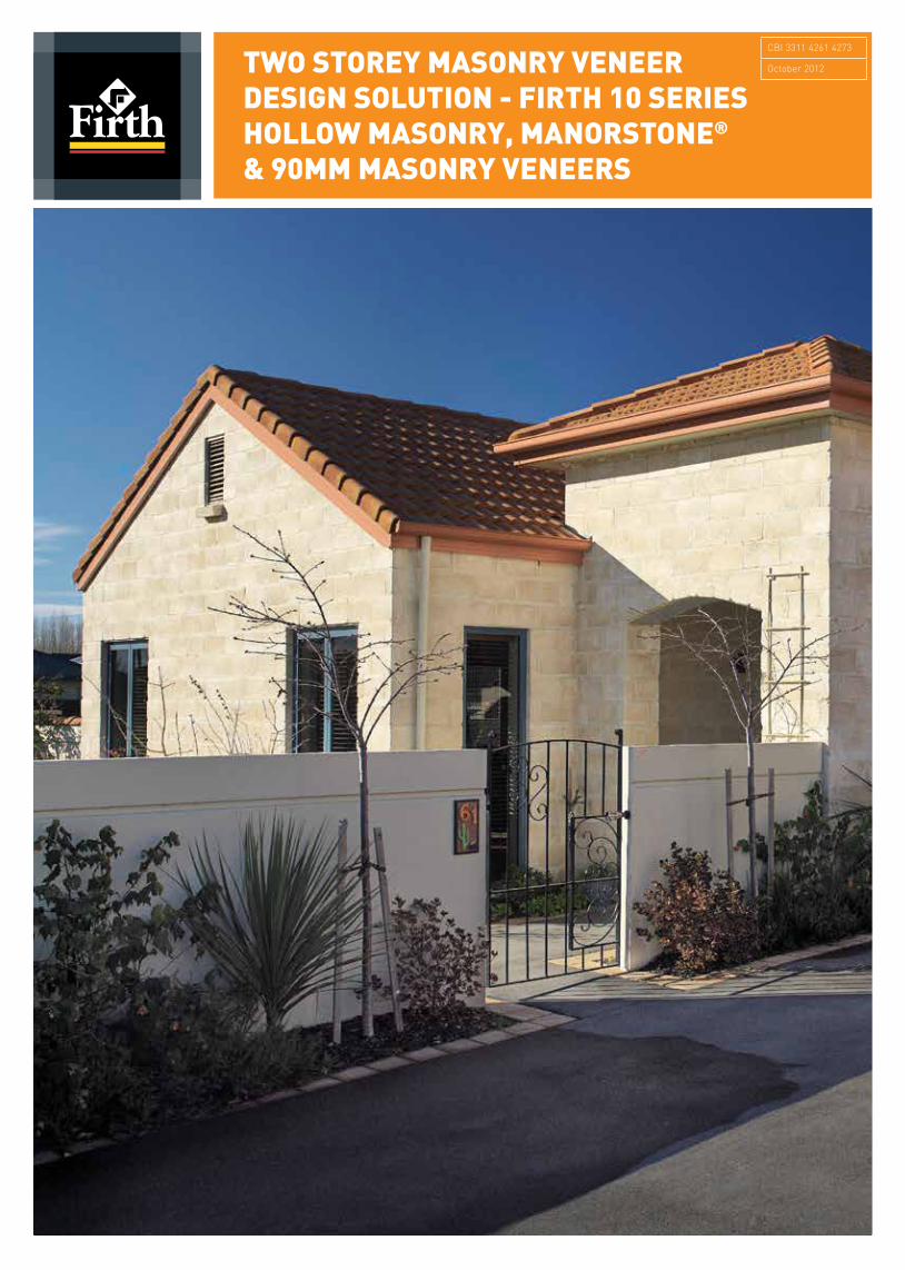
TWO STOREY MASONRY VENEER DESIGN SOLUTION - FIRTH 10 SERIES HOLLOW MASONRY, MANORSTONE® & 90MM MASONRY VENEERS
CBI 3311 4261 4273
October 2012
Unit 8 -‐ 1025 Ferry Road -‐ Ferrymead -‐ Christchurch 8023 -‐ 03 366 7955 -‐ www.engco.co.nz
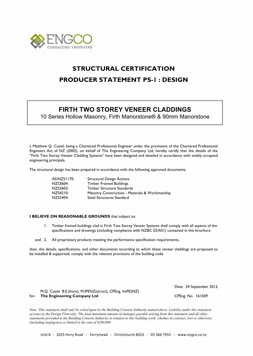
STRUCTURAL CERTIFICATION
PRODUCER STATEMENT PS-1 : DESIGN
FIRTH TWO STOREY VENEER CLADDINGS 10 Series Hollow Masonry, Firth Manorstone® & 90mm Manorstone
I, Matthew Q. Cusiel, being a Chartered Professional Engineer under the provisions of the Chartered Professional Engineers Act of NZ (2002), on behalf of The Engineering Company Ltd, hereby certify that the details of the “Firth Two Storey Veneer Cladding Systems” have been designed and detailed in accordance with widely accepted engineering principals. The structural design has been prepared in accordance with the following approved documents; AS/NZS1170: Structural Design Actions NZS3604: Timber Framed Buildings NZS3603: Timber Structure Standards NZS4210: Masonry Construction - Materials & Workmanship NZS3404: Steel Structures Standard I BELIEVE ON REASONABLE GROUNDS that subject to:
1. Timber framed buildings clad in Firth Two Storey Veneer Systems shall comply with all aspects of the
specifications and drawings (including compliance with NZBC E2/AS1) contained in this brochure and 2. All proprietary products meeting the performance specification requirements, then, the details, specifications, and other documents according to which these veneer claddings are proposed to be installed & supported, comply with the relevant provisions of the building code. Date: 24 September 2012
M.Q. Cusiel B.E.(hons), M.IPENZ(struct), CPEng, IntPE(NZ) for- The Engineering Company Ltd CPEng. No. 161509
Member IPENZ, ACENZ Note: This statement shall only be relied upon by the Building Consent Authority named above. Liability under this statement accrues to the Design Firm only. The total maximum amount of damages payable arising from this statement and all other statements provided to the Building Consent Authority in relation to this building work, whether in contract, tort or otherwise (including negligence) is limited to the sum of $200,000
GENERAL INFORMATION
Firth 10 Series Hollow Masonry, Manorstone® and
90mm Masonry Veneers may be used in accordance
with E2 AS/1 as a cladding up to 7.0m in height
by incorporating a galvanised steel shelf angle at
a maximum height of 4.0m above the top of the
foundation height.
The following information and attached Producer
Statement - PS1 - Design, will allow Designers/
Owners to apply for a building consent without the
need to consult a structural engineer for a specific
design for veneer support above 4.0m.
The designer must ensure that all other aspects of
the supporting structure, including, but not limited to;
site bearing capacity & wind speed, stud heights, wall
bracing, beam or lintel spans & sizes, veneer lintel bar
sizes, structure durability, etc, are all compliant with
E2 AS/1.
Any parts of the structure that do not comply with the
requirements of NZS3604 will require specific design.
MASONRY VENEER WEIGHTS
The approximate maximum weight for all of the Firth Masonry Veneers covered by these specifications is 14.7 kg for each unit or 195kg/m2 including mortar. There are 12 ½ blocks per square metre of cladding.
This weight is less than the maximum prescribed weight of 220kg/m2 for “Heavy” claddings in NZS3604, meaning that Firth 90mm Masonry Veneers can be used and detailed in accordance with E2 AS/1 for any building complying with the requirements of this document.
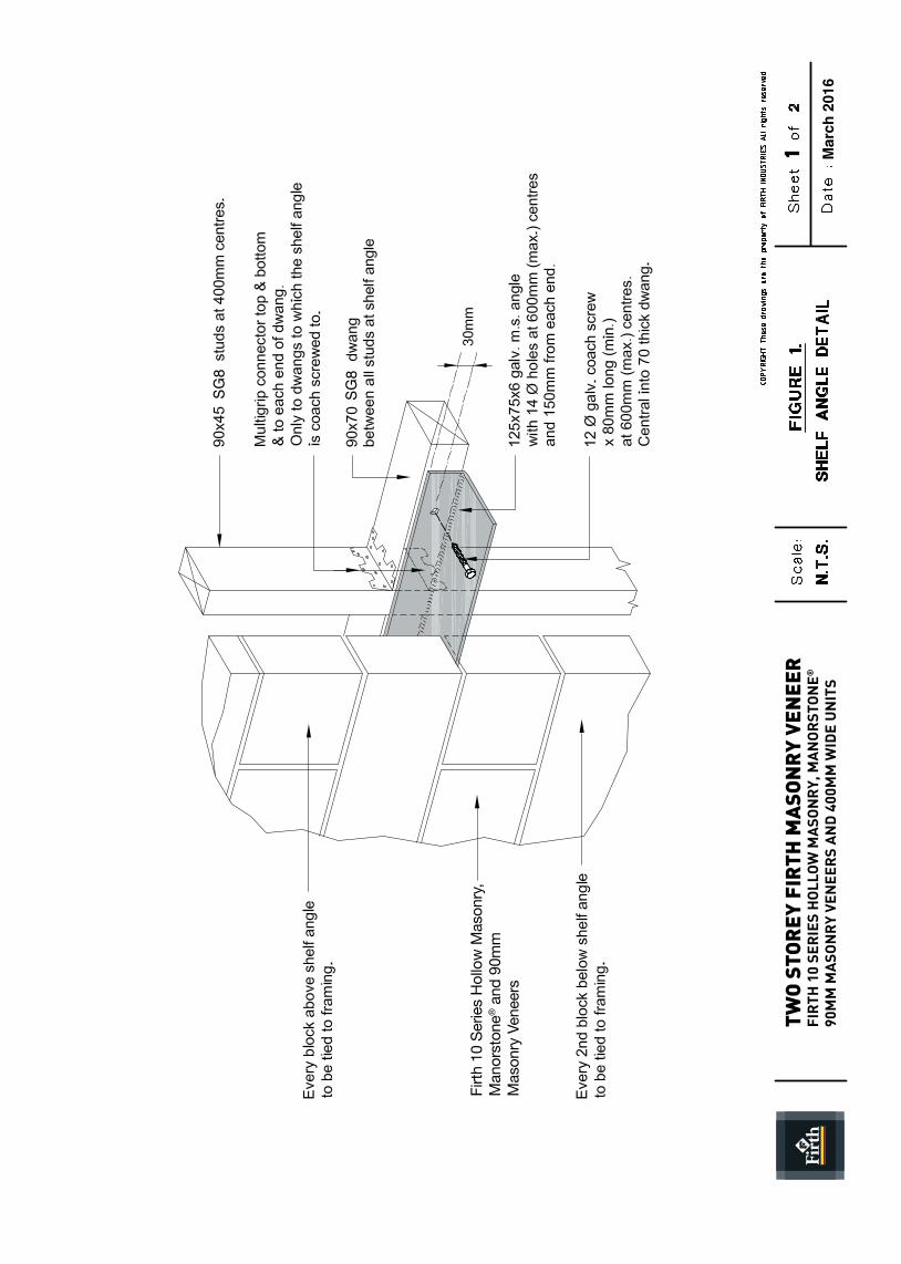
FIRTH MASONRY VENEER CONSTRUCTION AbOVE 4.0M
Install a galvanised 125x75x6mm steel shelf angle as indicated in figure 1.
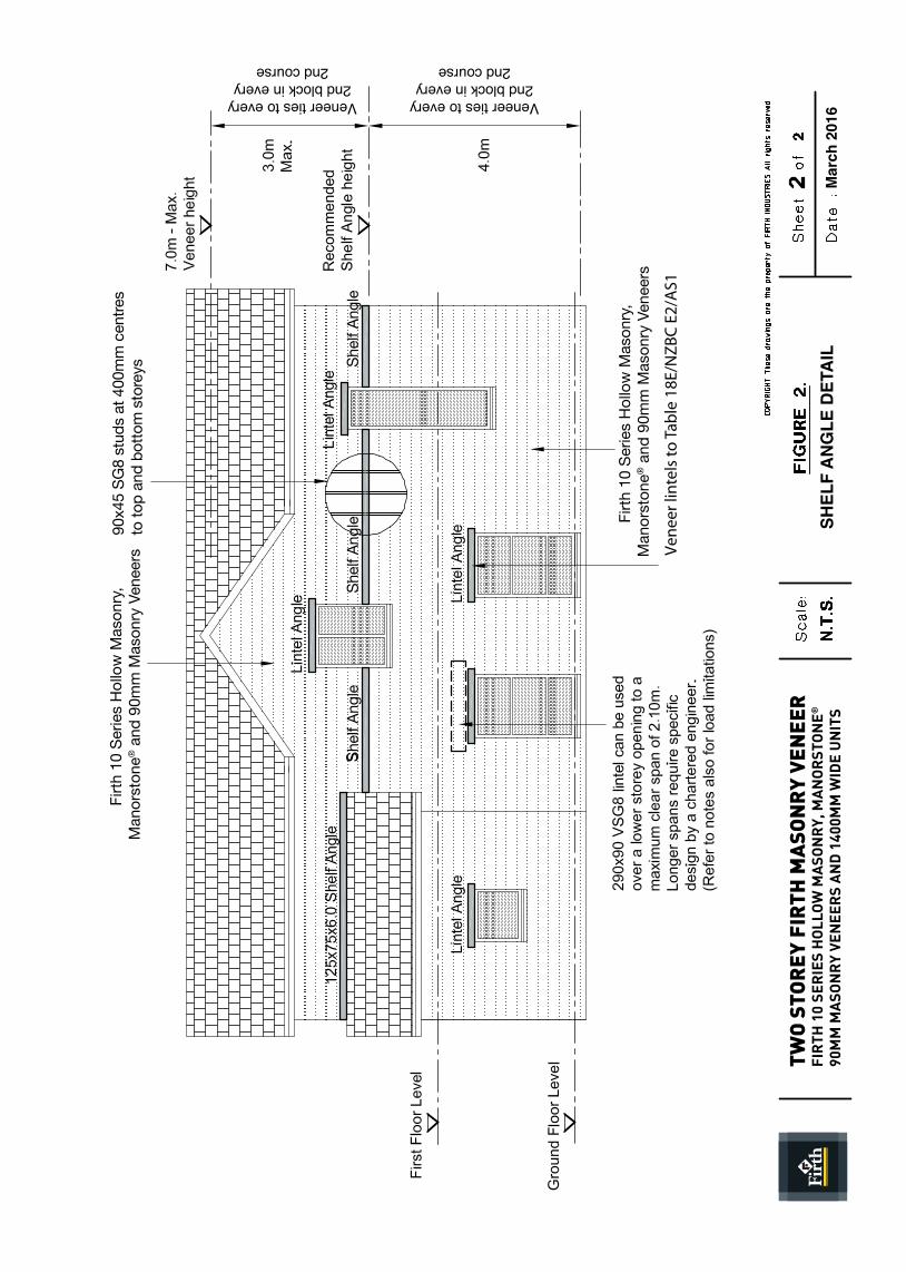
It is recommended that the shelf angles be positioned at 4.0m above the top of the foundations so that they are likely to be positioned between the upper level windows, thus, minimising the required length of the shelf angles.
Refer to figure 2. for recommended shelf angle positions.
The maximum height of the veneer cladding supported on top of the shelf angle shall not exceed 3.0m. This can be increased with specific design by a structural engineer.
Site measure the shelf angle lengths required and predrill as per figure 1. before galvanising. Where shelf angles need to be site cut or drilled, ensure an appropriate brushed on corrosion protection is applied.
Block between the studs as indicated in figure 1. Predrill 9mm pilot holes to the timber to avoid splitting of the timber blocking.
Where the Firth Masonry Veneer continues above a lower roof line, provide a galvanised 125x75x6mm steel shelf angle and 90x75 timber blocking between studs as required. This angle may rake along a slope as required. In this case the base block shall be cut to the required angle also.
MASONRY VENEER CAVITY DIMENSIONS
The masonry veneer cavity shall be in the range of 40mm (minimum) to 55mm (maximum) for Firth 10 Series Hollow Masonry, Manorstone® and 90mm Masonry Veneers. This is a departure from the
maximum limit imposed by NZS3604. The maximum dimension is governed by minimum veneer seating on the shelf angle detail of 70mm.LINTELS SUppORTING FRAMING / SHELF
ANGLE
All wall framing supporting a shelf angle, shall continue to the foundations or an internal slab thickening. Where a lower storey opening occurs below a shelf angle supporting masonry veneer cladding, a 290x90 VSG8 timber lintel can support the following load combinations, up to a 2.10m clear opening:
1. 4m of heavy clad roof (1/2 of 8m wide roof span including overhangs) with up to 0.5kPa snow load.
2. 3m of masonry veneer over a shelf angle (note: all veneer below the shelf angle is independently supported on masonry veneer lintel over the opening).
3. 3m of timber framed flooring & ceiling (1/2 of 6m wide floor span) with 2.0kPa Live Load.
The lintel shall be directly supported on 2-90x45 studs with two rows of dwangs to adjacent framing.
MASONRY VENEER TIES AND FIxINGS
Masonry veneer ties and fixings shall comply with the requirements of NZS 4210:2001. Ties shall be either hot-dip galvanised or Grade 316 stainless steel to comply with the durability requirements of E2 AS/1. Screws shall be either hot-dip galvanised or Grade 316 stainless steel, 35 mm x 12g Type 17 hex head screws for timber.
Brick ties shall be laid as required by E2 AS/1 and have a 5° down slope away from the wall frame to the masonry veneer.
MASONRY VENEER TIE SpACING
Ties shall be placed at the following positions & centres:
1. At window or door openings: Ties to every veneer unit
2. Veneers up to 4.0m above the foundations: Tie every second block in a course. (Stagger ties horizontally to form a “diamond” pattern.)
3. Veneers over lintel angles: Tie every unit
4. Veneers over 4.0m above the foundations: Tie every unit
WEEpHOLES AND VENTILATION OVER A SHELF ANGLE
Provide weep holes at 800mm centres above a shelf angle
WALL bRACING CALCULATIONS
Bracing may be calculated using the methods specified in NZS 3604.
Where the veneer height exceeds 3.0m, the minimum bracing units along an external line must be increased by 20% (i.e. from 10 BU’s/m to 12 BU’s/m), in accordance with NZS3604 clause 11.7.1 (f).
Firth
10
Serie
s Ho
llow
Mas
onry
, M
anor
ston
e® a
nd 9
0mm
M
ason
ry V
enee
rs
TWO
STO
REY
FIR
TH M
ASO
NR
Y VE
NEE
RFI
RTH
10
SER
IES
HO
LLO
W M
ASO
NR
Y, M
AN
OR
STO
NE®
90
MM
MA
SON
RY
VEN
EER
S A
ND
400
MM
WID
E U
NIT
SM
arch
201
6
SG8
SG8
90x4
5 SG
8 st
uds
at 4
00m
m c
entre
sto
top
and
botto
m s
tore
ys
Shel
f Ang
leSh
elf A
ngle
Shel
f Ang
le
Firth
10
Serie
s H
ollo
w M
ason
ry,
Man
orst
one®
and
90m
m M
ason
ry V
enee
rs
Firth
10
Serie
s H
ollo
w M
ason
ry,
Man
orst
one®
and
90m
m M
ason
ry V
enee
rs
TWO
STO
REY
FIR
TH M
ASO
NR
Y VE
NEE
RFI
RTH
10
SER
IES
HO
LLO
W M
ASO
NR
Y, M
AN
OR
STO
NE®
90
MM
MA
SON
RY
VEN
EER
S A
ND
140
0MM
WID
E U
NIT
SM
arch
201
6
Veneer ties to every2nd block in every
2nd course
Veneer ties to every2nd block in every
2nd course
SHEL
F A
NG
LE D
ETA
IL
Ven
eer l
inte
ls to
Tab
le 1
8E/N
ZB
C E
2/A
S1
n Manufacturing plants operating in compliance with relevant legislation
n All products manufactured according to ISO9001
n Strong focus on reducing transport impacts
n Masonry products manufactured according to Lean principles
n Greenstar and environmental product options available n Environmental Management Plans operative at all sites
4
4
4 4 4
n Effective acoustic barrier and fire resistant
n Longer and effective building life
n Demolished concrete can be recycled, reused or as clean fill
n Passive solar heated thermal mass provides energy efficiencies
n Highly durable, low maintenance
n Rainwater and process water reused in most products
For more on Firth’s
contribution to building
a sustainable tomorrow
today, visit www.firth.co.nz
or call us on 0800 800 576
for our free brochure.
CONCRETE AND MASONRY pRODUCTS: A SUSTAINAbLE bUILDING OpTION AND SOLUTION
4 4 4 4 4 4
4
October 2012 Chalis FIR21504© Copyright Firth 2012
0800 800 576www.firth.co.nz www.masterspec.co.nz
PRODUCTSPEC


