• 2.4 Kbps speed• Voice• Analog signal
• GSM/CDMA• 64 Kbps speed• Voice, higher coverage
• GPRS/EDGE• 114 Kbps speed• Voice, SMS, Email, Web
• UMTS/EVO• Up to 2Mbps• Large emails• 11s MP3 download
• HSPA+• Up to 10Mbps• Smart Phones take off
• 110Mbps• HD Video, Mobile TV, Enhanced security & mobility
• LTE_A• ~300Mbps• Carrier Aggregation
1980s1G
1990s2G
2000s3G
2010s
2016
4GLTE
2.5G
3.5G
4.5G
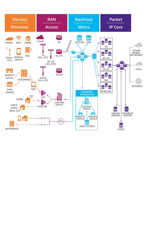
Devices
Premises
RAN
Access
Backhaul
Metro
Packet
IP Core
CENTRALOFFICE
HFC
OLT
DSLAM
BACK
HAUL OTTCDN CDN
5G
4G LTE
2G/3G
IMS
WIRELINE
ORIGINSERVER
VIDEO
DATABASESERVER
OTHERMOBILE
NETWORKS
PSTN
INTERNET
2G/3G
4G LTE
5G
2G/3GCELL SITE
5GCELL SITE
C-RAN
4G LTECELL SITE
FEMTO WIFI
SMALL CELL
MOBILEDEVICE
ENTERPRISE
ENTERPRISE
VOICE, VIDEO,
DATA, IOT
DATACENTER
REMOTEOFFICE
HOME
DAS
ONT
HOME
CENTRAL OFFICE
REMOTE OFFICE
REMOTE OFFICE
DATA CENTER
C-RAN
MANAGED ENTERPRISE
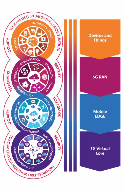
INTERNET OF THINGS
SEN
SORS
CONNECTIVITY
SCALIN
G
DENSIFICATION
DIVERSIFICATION
FLEX
IBIL
ITY
NETWO
RK
FUN
CTION VIRTUALIZATION
DISTR
IBUTED EDGE CLOUD
Devices andThings
5G RAN
MobileEDGE
5G VirtualCore
SOFTWARE-D
EFINED
CORE CLOU
DIFICATIO
N
TELE
COM OS (VIRTUALIZATION, ORCHESTRATIO
N)
TELECOM
OS (VIRTUALIZATION, ORCHESTRATIO
N)
SECU
RITY
TELE
COM
OS
SECURITY
TELECOM
OS
SECURITY
SECU
RITY
Global Mobile Radio Subscription,Data, & Revenue Growth
1995 2000 2005 2010 2015 2020
GSM EDGE UMTS HSPA+ LTE LTE-A LTE-Pro 5G
Subs
crip
tion
(Bn)
Reve
nue
($Tn
)
12
10
8
6
4
2
0
2.4
2
1.6
1.2
0.8
0.4
0
10GB
1 PB
1 EB
10 EB
110 EB
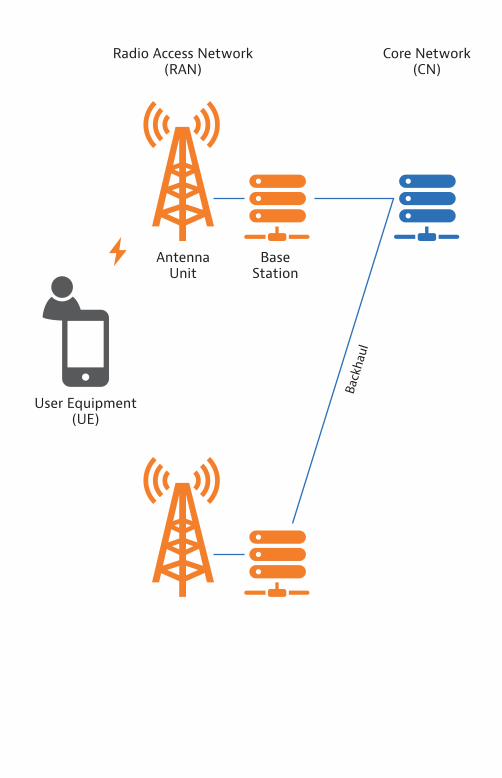
Radio Access Network(RAN)
Core Network (CN)
Antenna Unit
User Equipment (UE)
Base Station
Backhaul
NAS
UE
RRC
SDAP
PDCP
RLC
MAC
PHY
RAN
RRC
SDAP
PDCP
RLC
MAC
PHY
NAS
CN
U-Plane
PSTN
2G/GSM
A-bis
BSC
Gb
MSC
A-Int
Gn
BTS BTS
Gi
2.5G/GPRS
SGSN
GGSN
3G/3.5G
nodeB
Iub
RNC
GiPSTN
2G/GSM
A-bis
BSC
Gb
MSC
A-Int
Gn
BTS BTS
2.5G/GPRS
SGSN
GGSN
IuPS
IuCS
MME SGW
eNBCPRI
X2
SGi
4G/LTE
S11
PGWHSS
3G/3.5G
nodeB
Iub
RNC
GiPSTN
2G/GSM
A-bis
BSC
Gb
MSC
A-Int
Gn
BTS BTS
2.5G/GPRS
SGSN
GGSN
IuPS
IuCS
S1-MME
S6a S5/S8
S1-U
CRAN(BBU Hotel)S1-MME
4.5G/LTE-A
S1-UMME SGW
eNBCPRI
X2
SGi
4G/LTE
S11
PGWHSS
3G/3.5G
nodeB
Iub
RNC
GiPSTN
2G/GSM
A-bis
BSC
Gb
MSC
A-Int
Gn
BTS BTS
2.5G/GPRS
SGSN
GGSN
IuPSIuCS
S1-MME
S6a S5/S8
S1-U CPRI
Key economic idicators
1995 2000 2005 2010 2015 2020
Reve
nue
($Tn
)
Glo
bal c
ash
flow
($Tn
)
1.2
1
0.8
0.6
0.4
0.2
0
0.6
0.5
0.4
0.3
0.2
0.1
0
Global cash flowRevenue
Aviation
VR
Cellular Devices
Cloud Office
Multi-User UHDTelepresence
Smart City
ConsumerWearables
Connected Car
IoTInternet of �Things
Stadium
Virtual Surgery
Throughput
Kbps Mbps Gbps
Conn
ecti
on c
apac
ity
102
10
4
106
102
10
4
106
Latency
(ms)
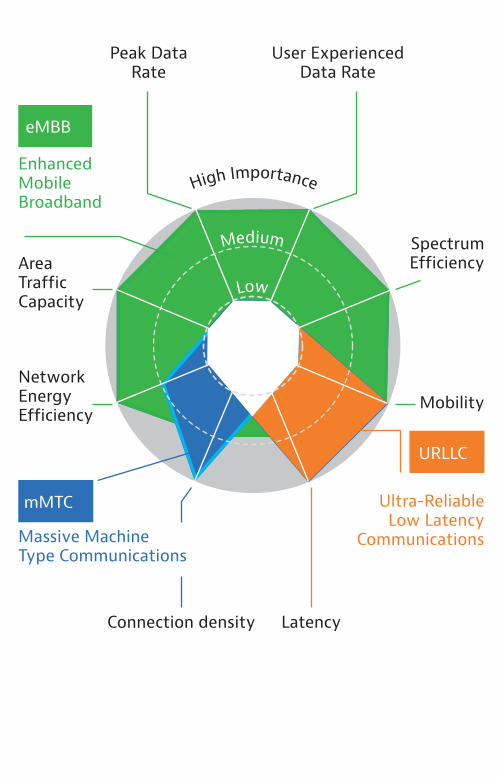
Medium
Low
eMBB
mMTC
URLLC
High Importance
Ultra-ReliableLow Latency
Communications
EnhancedMobileBroadband
Massive MachineType Communications
Peak Data Rate
Connection density Latency
Network Energy Efficiency
Area TrafficCapacity
SpectrumEfficiency
Mobility
User ExperiencedData Rate
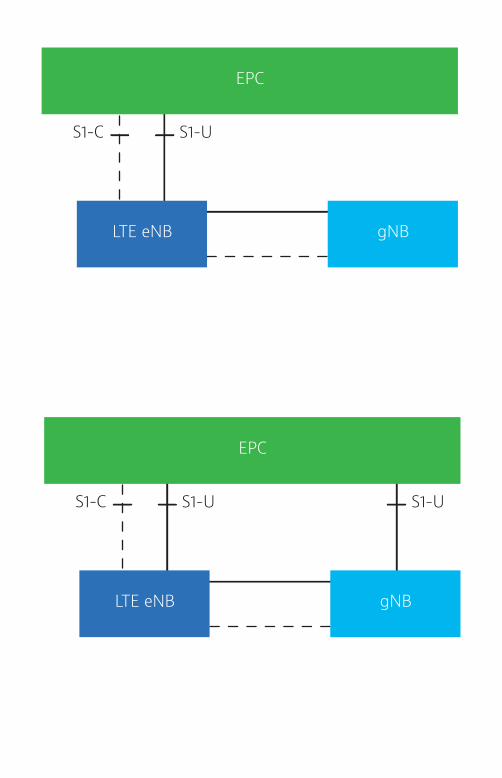
S1-US1-C
EPC
LTE eNB gNB
S1-US1-C S1-U
EPC
LTE eNB gNB
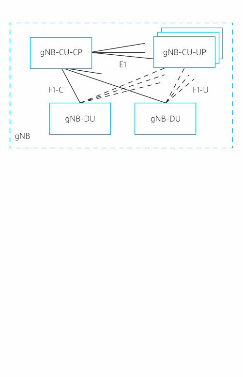
gNB-CU-CPE1
F1-UF1-C
gNB
gNB-CU-UP
gNB-DU gNB-DU
NEF NRF PCF UDM
AUSF AMF
(R)AN UPFUE
SMF NWDAF
AF
DN
Nnef Nnrf Npcf NudmNausf Namf Nsmf Nnwdaf
N1 N2 N4
N3 N6
Naf
NEFNetwork Exposure Function
NRFNetwork Repository Function
PCFPolicy Control Function
UDMUnified Data Management
AFApplication Function
AUSFAuthentication Server Function
AMFAccess & MobilityManagement Function
SMFSession Management Function
NWDAFNetwork Data Analytics Function
UEUser Equipment
RANRadio Access Network
UPFUser Plane Function
DNData Network
QoS flow handling QoS
CU
DU
RU
FH
SDAP
QoS Flows
Radio Bearers
F1/W1 Split 2RLC Channels
Logical Channels
Split 6Transport Channels
Split 7-3
Split 7-2
Split 7-1
Split 8
CC1 CCn CC1
PDCP
RLC
MAC
PHY
ROHC ROHC ROHC
Security Security Security
Seg, ARQ
HARQ HARQ HARQ
Multiplex, UE1 Multiplex
Scheduling/Priority Handling
Rate matching=> scrambling
BF Precode(DL)/Equalisation(UL) => RE-mapping
Modulation=> layer mapping
IFFT => CP addition => D/A conversion => Analog BF
Seg, ARQ Seg, ARQ
F1-C F1-U
S1-MME
4.5G/LTE-A
5G
S1-UMME SGW
eNBCPRI
X2
SGi
4G/LTE
S11
PGWHSS
3G/3.5G
nodeB
Iub
RNC
GiPSTN
2G/GSM
A-bis
BSC
Gb
MSC
A-Int
Gn
BTS BTS
2.5G/GPRS
SGSN
GGSN
IuPSIuCS
S1-MME
S6a S5/S8
S1-U CPRI
XnN9
F1/O-RAN
eCPRI/O-RAN
N6
N2 N12
N11 N4
UPF
AMFAUSF
SMF
CRAN(BBU Hotel)
DU
CU (+UPF)
10GB
1PB 1EB
10EB
110EB
Projected cash flow with forecast benefit of softwarization and RAN disaggregation to reduce CAPEX & OPEX
Key economic indicators(bubble volume = data/month)
1995 2000 2005 2010 2015 2020
Reve
nue
($Tn
)
Glo
bal C
ash
Flow
($Tn
)
1.2
1
0.8
0.6
0.4
0.2
0
0.6
0.5
0.4
0.3
0.2
0.1
0
Global cash flowRevenue (no softwareization)Revenue (with softwareization)
TD
2 2.5 3 3.5 4 4.5 5
SUL
Frequency (GHz)
n1
Band
Dup
lex
FDDn2 FDDn3 FDDn5 FDDn7 FDDn8 FDDn12 FDDn20 FDDn25 FDDn28 FDDn34 TDDn38 TDDn39 TDDn40 TDDn41 TDDn51 TDDn66 FDDn70 FDDn71 FDDn75 SDLn76 SDLn77 TDDn78 TDDn79 TDDn80 SULn81 SULn82 SULn83 SULn84 SULn86
0 0.5 1 1.5
UL DL
TD
30
Frequency (GHz)
35 40 45
TDDn258 TDDn260 TDDn261 TDD
20 25
Band
Dup
lex
n257
π/2-BPSK QPSK 16QAM
64QAM 256QAM
Subcarriers
Subcarriers
Subcarriers
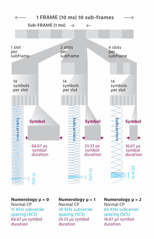
Sub-FRAME (1 ms)
1 FRAME (10 ms) 10 sub-frames
4 slots per subframe
2 slots per subframe
1 slotper subframe
Numerology µ = 0Normal CP15 KHz subcarrier spacing (SCS)66.67 µs symbol duration
Numerology µ = 1Normal CP30 KHz subcarrier spacing (SCS)33.33 µs symbol duration
Numerology µ = 2Normal CP60 KHz subcarrier spacing (SCS)16.67 µs symbol duration
66.67 µs symbol duration
Subcarriers
Subcarriers
Subcarriers
14 symbolsper slot
14symbolsper slot
14 symbolsper slot
Symbol Symbol Symbol
16.67 µs symbol duration
33.33 µs symbol duration
60 kHz
30 kHz
15 kHz
Sub-FRAME (1 ms)
1 FRAME (10 ms) 10 sub-frames
16 slots per subframe
8 slots per subframe
4 slots per subframe
Numerology µ = 2Extended CP60 KHz subcarrier spacing (SCS)16.67 µs symbol duration
Numerology µ = 3Normal CP120 KHz subcarrier spacing (SCS)8.33 µs symbol duration
Numerology µ = 4Normal CP240 KHz subcarrier spacing (SCS)4.16 µs symbol duration
Subcarriers
Subcarriers
Subcarriers
Subcarriers
Subcarriers
Subcarriers
240 kHz
60 kHz
Symbol Symbol Symbol
4.16 µs symbol duration
8.33 µs symbol
duration
16.67 µs symbol
duration
120 kHz
12symbolsper slot
14 symbolsper slot
14 symbolsper slot
Slot 18(14 symbols)
Reso
urce
blo
ck(1
2 su
bcar
riers
)
Slot 0(14 symbols)
Subframe 0(1 ms)
Subframe 9(1 ms)
Frame(10 ms)
Resourceelement
Slot 1(14 symbols)
Slot 19(14 symbols)
Numerology 1 30 KHz subcarrier spacing
Radio channel
Transmitter Receiver
Complex radio channel
Transmitter Receiver
Radio channel
Transmitter Receiver
Transmitter Receiver
Radio channel
Radio channel
Transmitter Receiver
Transmitter Receiver
Radio channel
Radio channel
Transmitter Receiver
Channel State Indicator-Reference
Signal (CSI-RS) on 32 ports
Channel State Indicator-Reference
SSB0PSS, SSS PSS, SSS
SSB1
SSB2
SSB3
Signal (CSI-RS) on 8 ports each
Channel State Indicator-Reference
Signal Resource Indicator (CRI)
Synchronization Signal Block (SSB)
Channel Quality Indicator (CQI)
Rank Indicator (RI)
Precoding Matrix Indicator (PMI)
Channel Quality Indicator (CQI)
Rank Indicator (RI)
Precoding Matrix Indicator (PMI)
SSB2
SSB3
SSB0
PSS, SSS PSS, SSS
SSB1
Channel State Indicator-Reference
Signal (CSI-RS) on 32 ports
Channel State Indicator-Reference
Signal (CSI-RS) on 8 ports each
Channel State Indicator-Reference
Signal Resource Indicator (CRI)
Synchronization Signal Block (SSB)
Channel Quality Indicator (CQI)
Rank Indicator (RI)
Sounding Reference Indicator (SRS)
Channel Quality Indicator (CQI)
Rank Indicator (RI)
Sounding Reference Indicator (SRS)
CRAN(BBU Hotel)
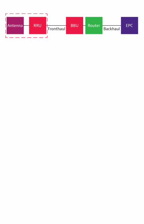
Fronthaul
eNBCPRI
CPRIS1-U S1-MME
S1-MME
MME
SGWS1-U
4G/LTE 4.5G/LTE_A
Backhaul
small cells
Antenna RRU BBU Router EPCBackhaulFronthaul
Antenna RRU BBU Router EPCBackhaulFronthaul
Antenna RRU BBU Router EPCBackhaulFronthaul
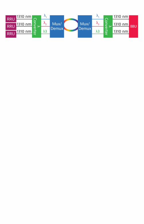
RRU
RRU
BBUMux/
Demux
λ1
λ2
λ3
λ2
λ3
RRUλ1
Mux/Demux
1310 nm
1310 nm
1310 nm
1310 nm
1310 nm
1310 nm
Mux/Demux
Mux/Demux
λ1
λ2
λ3
RRU
RRU
RRU
λConverter
λConverter
BBU
λ1
λ2
λ3
Air I
nter
face
Net
wor
k In
terf
ace
Layer 2
Layer 1
Sync SyncUserplane
SAPCM SAPS SAPIQ
Digitized Radio Base StationInternal Interface Specification
Radio Equipment Control (REC)
Radio Base Station System
Radio Equipment (RE)
Controland
Management
Layer 2
Layer 1
Userplane
SAPCM SAPS SAPIQ
Controland
Management
Time Division Multiplex
Layer 2
Layer 1
User Plane
IQ D
ata
Vendor Specific
Ethernet
HD
LC
L1 Inband ProtocolControl
& ManagementPlane
SYNC
ElectricalTransmission
OpticalTransmission
1 2 3 15 16 p-1 p 63 64 65 66 67 127 255
0 0 0 0 0 0 0 0 1 1 1 1 1 3
1 2 3 15 16 p-1 p 63 0 1 2 3 63 63Index of subchannel Ns=0
Index of controlwordwithin subchannel Xs=0
Index of control wordX=0
1 hyperframe (66.67 µs)1 basic frame
Sync byte K28.5 CW130 contains: RAI, SDI, LOS, LOF
Definitions
Basics
Architecture
Profiles
NetworkRequirements
TimingCharacteristics
G.8275
G.8273 Framew
Frequency (G.826x)
Time/Phase(G.827x)
G.8261
G.8261.1
G.8262SyncE
G.8263Packet
G.8264 Timing inf
G.8265 Packet
G.8260
G.8265.1 Freq.
G.8275.1 FTS
G.8275.2 PTS/APTS
G.8271
G.8271.x
G.8271.1 FTS
G.8273.1 T-GM
G.8273.3 TC
G.8273.4 APTSC
G.8271.2PTS/APTS
G.8273.2T-BC/T-TSC
G.8272 PRTC
PNT-FPRC
PNT-F
PEC-M
PEC-S-F
PNT-F
Physical Layer based
synchronization network
C: PEC-S-F input packet network limits
E: End application requirements(e.g., frequency accuracy)
B: PEC-M output packet network limits
A: PRC, EEC, SSU OR SEC network limits
Packet master clock Timing
packets
End application clock
C2
C1
D: PEC-S-F outputnetwork limits (deployment case 2)
End application clock
Packet network
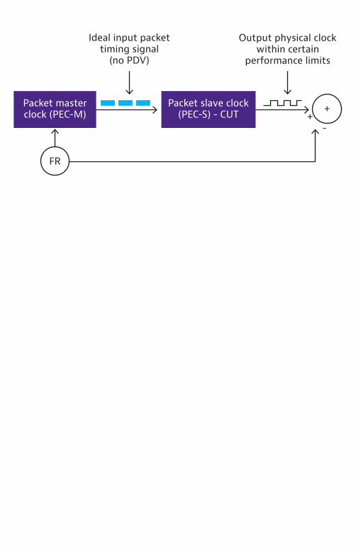
Packet slave clock (PEC-S) - CUT
Packet master clock (PEC-M) +
-
+
Ideal input packet timing signal
(no PDV)
Output physical clock within certain
performance limits
FR
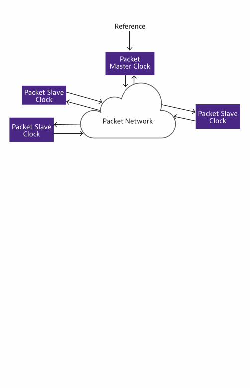
Packet Network
Reference
Packet Slave Clock
Packet Slave Clock
Packet Slave Clock
Packet Master Clock
Deployment Case 1
Network time reference(e.g., GNSS engine)
Endapplication
A B C E
End applicationTime clock
Packet networkPRTC T-GM T-BC T-TSC
Network time reference(e.g., GNSS engine)
A B C D E
End applicationTime clock
Packet networkPRTC T-GM T-BC T-TSC
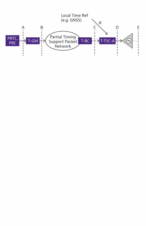
Deployment Case 2
A BA’
C
Partial Timing Support Packet
Network
D E
Local Time Ref (e.g. GNSS)
T-TSC-AT-BCPRTC,PRC T-GM
A B C
Partial Timing Support Packet
Network
D E
T-TSC-PPRTC,PRC T-GM
BBU RRU
Option4
Option5
Option6
Option7
Option8
CPRI
Option2
Option3
Option1
HighMAC
LowMAC
HighPHY
LowPHY
LowPHY
RF
RRC PDCP HighRLC
LowRLC
HighRLC
LowRLC
HighMAC
LowMAC
HighPHYRRC PDCP
DO
WN
LIN
KU
PLIN
K
Option4
Option5
Option6
Option7
Option8
Option2
Option3
Option1
HighMAC
LowMAC
HighPHY
LowPHY
LowPHY
RF
RRC PDCP HighRLC
LowRLC
HighRLC
LowRLC
HighMAC
LowMAC
HighPHYRRC PDCP
DO
WN
LIN
KU
PLIN
K
CU DU/RU
F1
CU/DU RU
Option4
Option5
Option6
Option7
Option8
eCPRI
Option2
Option3
Option1
HighMAC
LowMAC
HighPHY
LowPHY
LowPHY
RF
RRC PDCP HighRLC
LowRLC
HighRLC
LowRLC
HighMAC
LowMAC
HighPHYRRC PDCP
DO
WN
LIN
KU
PLIN
K
Coding
Ratematching
Scrambling
Modulation
Layermapping
Pre-coding
RE mapping
IFFT/CPaddition
D/A
Analog BF
De-coding
Ratede-matching
De-scrambling
De-modulation
Channelestimation/Equalization
& IDFT
REde-mapping
Digital BF Digital BF
FFT/CPremoval
A/D
Analog BF
Option6
Option7-3 (DL)
Option7-2
Option7-2a
Option7-1
Option8
MAC
ID (eCPRI)
IID (eCPRI) IU (eCPRI)
E (CPRI) E (CPRI)
MAC
PHY PHY
RF RF
TransportNetwork
eCPRI Radio Equipment Control (eREC)
User Plane
Sync Control & Mgmt
SAPU SAPS SAPCM
Transport Network Layer
StandardProtocols
eCPRI specific
eCPRI Radio Equipment(eRE)
User Plane
Sync Control & Mgmt
SAPU SAPS SAPCM
Transport Network Layer
StandardProtocols
eCPRI specific
Option4
Option5
Option6
Option7
Option8
Option2
Option3
Option1
HighMAC
LowMAC
HighPHY
LowPHY
LowPHY
RF
RRC PDCP HighRLC
LowRLC
HighRLC
LowRLC
HighMAC
LowMAC
HighPHYRRC PDCP
DO
WN
LIN
KU
PLIN
K
CU RUDU
F1 eCPRI
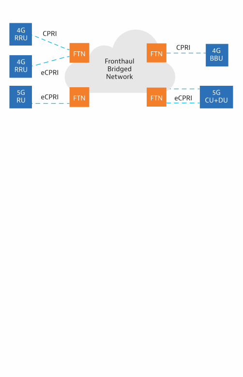
FronthaulBridgedNetwork
FTN
FTN
FTN
FTN
4GBBU
5GCU+DU
4GRRU
4GRRU
5GRU
CPRI
eCPRIeCPRI
eCPRI
CPRI
5G RU
4G BBU
5GCU+DU
CPRI
eCPRI
RoEEthernet/
WDMRoE
4G RRUCPRI
eCPRI
Core Edge Access
NGC
NGC
RRC PDCP RLC MAC RF
RF
HighPHY
RRC RLC MACPDCP
Radio Site
LowPHY
LowPHY
HighPHY
eMBB
uRLLC
4G/LTE EPCS1-MME
EPS-NAS S6aHSS
S11
S5/58
SGi
Gx
S10
eNB
S1-U
PGW
MME
SGW
PCRF
PGW
SGW
S11
S5/58
SGi
S10
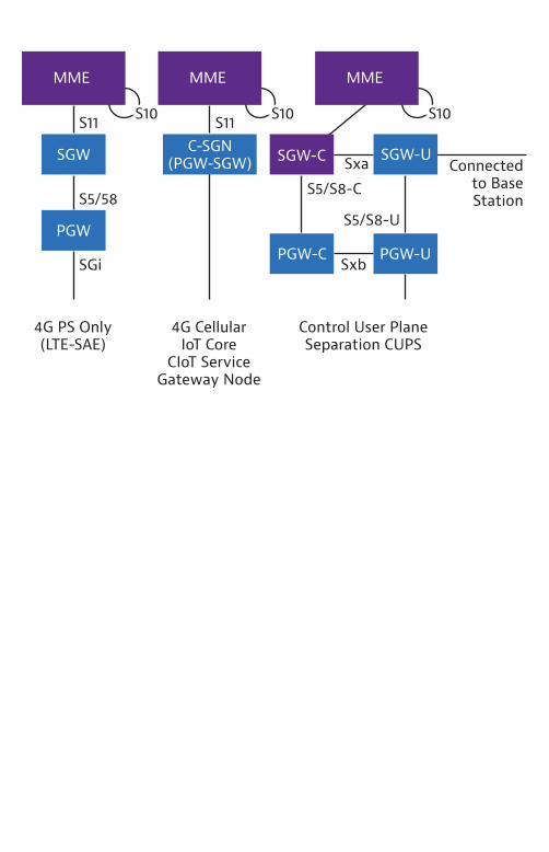
MME
C-SGN(PGW-SGW)
S11 S10
Sxa Connected to Base Station
S5/S8-C
S5/S8-U
MME
PGW-USxb
SGW-U
S10
SGW-C
MME
PGW-C
4G PS Only (LTE-SAE)
4G CellularIoT Core
CIoT Service Gateway Node
Control User Plane Separation CUPS
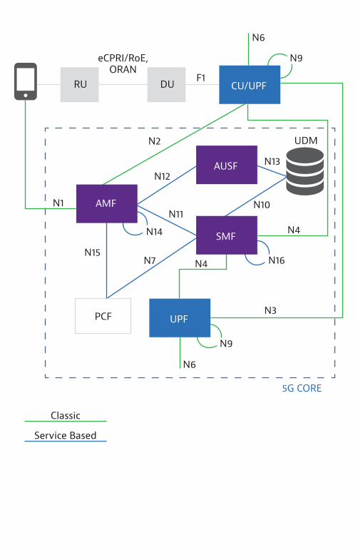
eCPRI/RoE, O-RAN
N9
N6
N16
N9
CU/UPF
UPF
SMF
AMF
AUSF
PCF
UDM
RU DU
N6
F1
N3
N2
N4
N1
N15 N7
N14N11
N12
N13
N10
N4
5G CORE
4G/LTE EPCS1-MME
EPS-NAS S6aHSS
S1-US11
S5/58
SGi
Gx
S10
N14
N11
N12 N13
N10
N4
5G CORE
N6
F1
N3
N2
N4
N1
N15N7
PGW
eNB
MME
PCRF
eCPRI/RoE,O-RAN
N9
N6
N16
N9
DURU
UDM
PCF
AUSF
AMF
SMF
UPF
CU/UPF
SGW
NF_A(Consumer)
Request
NF_B(Producer)
Response
Subscribe
Notify
NF_A(Consumer)
NF_B(Producer)
3GPP TS 23.501
JSON
R16(under consideration)
R15
JSON
HTTP/2
TLS
TCP
HTTP/3
IP IP
QUIC
L2 L2
3GPP TR 29.893
eCPRI/RoE,ORAN
N9
N6
N16
N9
CU/UPF
UPF
SMF
AMF
AUSF
UDM
RU DU
N6
F1
N3
N2
N4
N1
N15N7
N14
N11
N12N13
N10
N4
5G CORE
Classic
Service Based
PCF
NEF NRF PCF UDM
AUSF AMF
(R)AN UPFUE
SMF NWDAF
AF
DN
Nnef Nnrf Npcf NudmNausf Namf Nsmf Nnwdaf
N1 N2 N4
N3 N6
Naf
Classic
Service Based
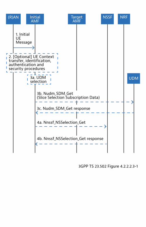
NRFNSSFTargetAMF
InitialAMF
(R)AN
2. [Optional] UE Context transfer, identification, authentication and security procedures
3GPP TS 23.502 Figure 4.2.2.2.3-1
3a. UDM selection
UDM
3b. Nudm_SDM_Get(Slice Selection Subscription Data)
3c. Nudm_SDM_Get response
4a. Nnssf_NSSelection_Get
4b. Nnssf_NSSelection_Get response
1. Initial UE Message
NAS-MM NAS-MM
NG-AP
SCTPIPL2
L1
AMFN25G-AN
NG-APSCTP
IPL2
L1
Relay
5G-ANProtocol
Layer
5G-ANProtocol
Layer
UE
PDU Layer
5G-AN
GTP-U
UDP/IP
L2
L1
Relay
5G-ANProtocol
Layer
5G-ANProtocol
Layer
UE UPF
RelayPDU Layer
GTP-U
UDP/IPL2
L1UPF
(PDU Session Anchor) N6N9N3
Application
GTP-U
UDP/IP
L2
L1
GTP-U
UDP/IP
L2
L1
PFCP
UDP
IPL2
L1
CP function
Sx and N4 reference point
PFCP
UDP
IPL2
L1
UP function
GTP-U
UDP
IPL2
L1
CP function
Sx and N4 reference point
GTP-U
UDP
IPL2
L1
UP function
5G RAN
Ethernet Packet Filters
UPF
UE
NG-RAN 5GC
Radio NG-U
NB UPF
PDU Session
Radio Bearer NG-U Tunnel
Radio Bearer
QoS Flow
QoS Flow
QoS Flow
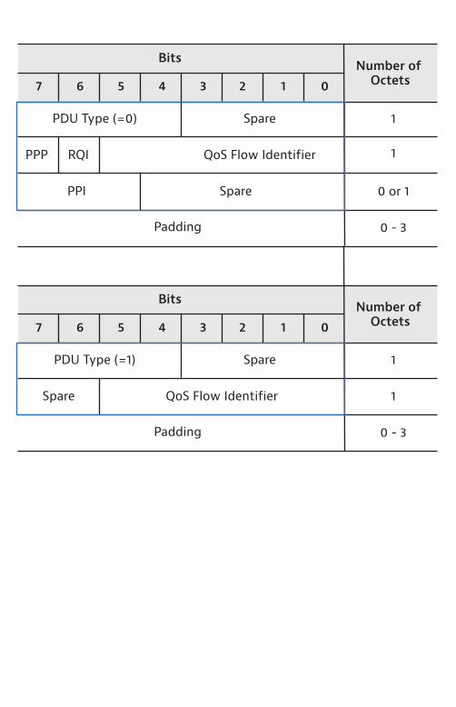
1
0 - 3
Spare
Spare QoS Flow Identifier
Padding
7 6 5 4 3 2 1 0
Number of Octets
Bits
PDU Type (=1) 1
1
0 or 1
0 - 3
Spare
PPP QoS Flow Identifier
PPI Spare
RQI
Padding
Number of Octets
Bits
PDU Type (=0) 1
7 6 5 4 3 2 1 0
Slide Dedicated CP NFs
URLLCSlice #1
eMBBSlice #2
mIoTSlice #3
Common Control Network Functions (CCNF)
End to End (E2E) SlicingOrchestration and Management System
UE SpecificCP NFs
Slice DedicatedUP NFs
CommonCP NFs
MECe.g. V2X App
UPF UE #1Slice #1
MECe.g. HD Maps
DNN
DNN
DNN
Edge DCNote: RAN functional splits into CU, DU, RU components are not shown in this diagram
Local DC Central DC
AMF common to all network slices instances serving a single UE
Slice specific PDU Sessions
Network Slice Instance #3 inc. SMF, UPF
Network Slice Instance #1and #2 inc. SMF, UPF, MEC
UPF UE #1Slice #2
UPF UE #2Slice #3
SMF UE #1Slice #1
SMF UE #1Slice #2
SMF UE #2Slice #3
AMF UE#1Slice #1 & #2
UE #1URLLCeMBB
UE #2mIoT
UDM NSSF NRF AUSF PCF
AMF UE #2Slide #3
RAN
SMF and UPF dedicated to each slice
SD
SD
SST
NSSAI
SST
S-NSSAI #1
S-NSSAI #nUE RAN AMF
HSS
NRFRRC
(NSSAI*)NAS
(NSSAI)
NSSAI
AMF selection function based on
TempID or NSSAI
Enquiry NSSF for (S)-NSSAI –NS-ID
mapping(**)
SMF selection function
Retrieves NFs from
NS-ID
SMF #1
SMF #n
UPF#1
UPF#n
Slice specific network functions
MEC Application
(VNF)MEC Application
(VNF)MEC Application
(VNF)
VirtualizationInfrastructure
(e.g. NFVI)
VirtualizationInfrastructure Manager
(e.g. VIM)
MEC Platform(MEP) (VNF)
MEC Platform(MEP) (VNF)
MEC System Level Management:Operations Support System (OSS)
& MEC Orchestrator (MEO)
MEC Application
(VNF)
Client App
Cloud Back-end
for Service
Web
RemoteServers
MEC Host
UE Level
EdgeLevel
Remote Level
MEC Host
MEC platform
MECplatform MEC
service
MEC App
service
MEC AppMetadata
Data Plane
Service registry
Traffic rules
controlDNS
handling
Mp3
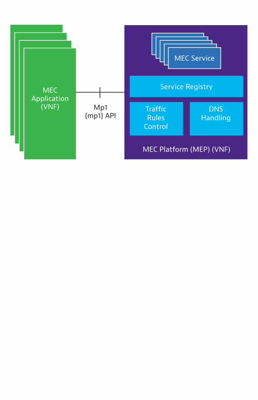
Mp1
Infr
astr
uctu
reSe
rvic
e
MEC Application
(VNF) Mp1{mp1} API
MEC Service
Service Registry
Traffic Rules
Control
MEC Platform (MEP) (VNF)
DNSHandling
MEC Service e.g. Location
MEC Service e.g. Location
MEC Service e.g. RNIS
MEC Service
Service Registry
Traffic Rules Control
MEC Platform (MEP) (VNF)
DNSHandling
{3rd Party Dev} API
{ls} MEC API
{rni} MEC API
{3rd Party Dev} MEC API,e.g. RNI
MEC Application A
(Service Consuming &
Producing)(VNF)
MEC Application B
(Service Consuming)
(VNF)
MEC Application C
(Service Producing)
(VNF)
MEC Application D
(VNF)
UE Measurement Report
UE Handover(Cell Change)
UE Timing Advance
UE Carrier Aggregation Reconfiguration
Radio Access Bearer Establishment/Modification/Release
S1 Bearer Establishment/ Modification/Release
Cells associated with MEC App
Queries Notifications
Bearers Associated with MEC App
Per UE,S1-U Bearer Info
Per Cell, Layer 2 Measurement Info
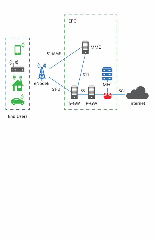
InternetS-GW
S11
S10
S5
MME
EPC
P-GW
SGi
End Users
eNodeB MEC
S1-U
S1-MME
InternetS-GW
S11
S5
MME
EPC
P-GW
SGi
End Users
eNodeB MECS1-U
S1-MME
NSSF NEF NRF PCF
AUSF
UE
AMF
(R)AN UPF
SMF
UDM
N3 N6
(Local Area)Data
Network
MEC Platform
MEPM
OSS & MEO
N4
MEC System
Naf
VirtualizationInfrastructure
VIM
Application Service
Hos
t Le
vel (
Dis
trib
uted
)Sy
stem
Lev
el
API Invoker
CAPIF Core Function (CCF)
PLMN Trust Domian
CAPIF-1e
CAPIF APIs Service APIs
CAPIF-1CAPIF-2e
CAPIF-3
CAPIF-4
CAPIF-5
CAPIF-2
MEP Application
Functional Element of the MEP Platform
API Invoker
API ExposingFunction (AEF)
API PublishingFunction (APF)
API ManagementFunction (AMF)
API Provider Domain
MEP Application
MEP Service/MEC Service Producing
Application
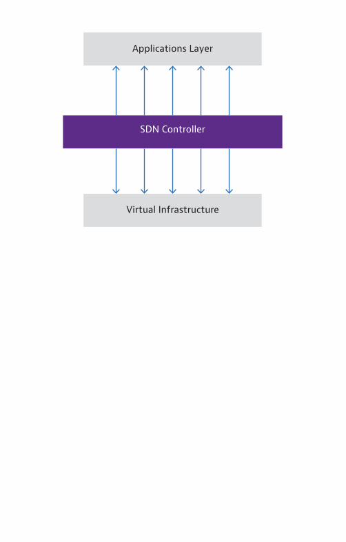
Applications Layer
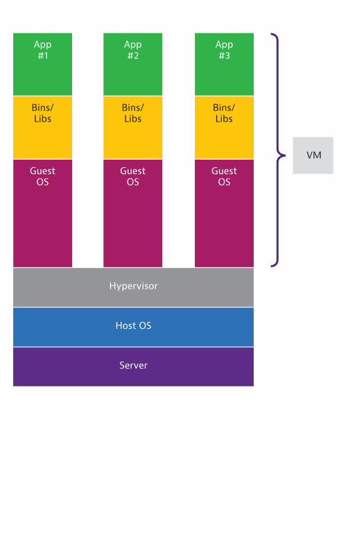
Virtual Infrastructure
SDN Controller
VM
Host OS
Hypervisor
App#3
Bins/Libs
Guest OS
App#2
Bins/Libs
Guest OS
App#1
Bins/Libs
Guest OS
Server
Server
Host OS
Docker Engine
Bins/Libs
App#1
Bins/Libs
App#2
Bins/Libs
App#3
Container
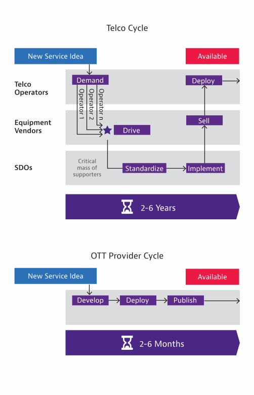
New Service Idea
New Service Idea
Available
Demand Deploy
SellDrive
ImplementCritical mass of
supporters
TelcoOperators
EquipmentVendors
SDOsO
perator 1O
perator 2O
perator n
Standardize
2-6 Years
Available
Develop Deploy Publish
2-6 Months
Telco Cycle
OTT Provider Cycle
Digital Storefront(Automated Customer & Business Management)
Inter-Domain Integration Fabric
Domain Managed Infrastructure Resources
E2E Service Management Domain
Management Domain
Management Service Implementations
Intra-Domain Integration Fabric
Management Service Implementations
DomainData
Services
E2EIntelligence
Common Data
Services
DomainIntelligence
DomainAnalytics
DomainData
Collection
DomainOrchestration
E2E Orchestration
E2E Data Collection
E2E Data Services
E2E Analytics
DomainControl
Physical Virtual Xaas
ZSM Scope
Data Services
Data Services
Data Services
Inter-Domain Integration Fabric
19% Energy and Utilities
18% Manufacturing
13% Public Safety
12% Healthcare
10% Public Transport
9% Media and Entertainment
8% Automotive
6% Financial Services
1% Agriculture
Scal
e
Band
wid
th
Late
ncy
Den
sifi
cati
on
Mob
ility
End-
to-e
nd
4% Retail
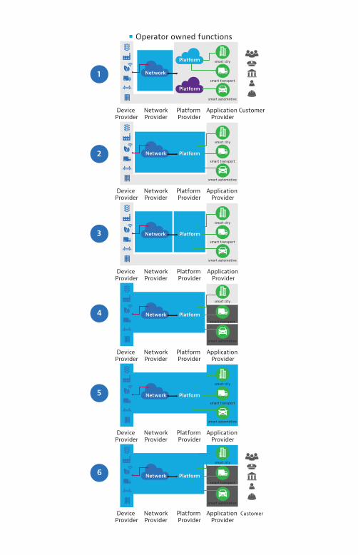
Network
Platform
Platform
Device Provider
NetworkProvider
Platform Provider
Application Provider
Customer
smart city
smart transport
smart automotive
Network Platform
Device Provider
NetworkProvider
Platform Provider
Application Provider
smart city
smart transport
smart automotive
Network Platform
Device Provider
NetworkProvider
Platform Provider
Application Provider
smart city
smart transport
smart automotive
Network Platform
Device Provider
NetworkProvider
Platform Provider
Application Provider
smart city
smart transport
smart automotive
Network Platform
Device Provider
NetworkProvider
Platform Provider
Application Provider
smart city
smart transport
smart automotive
Network Platform
Device Provider
NetworkProvider
Platform Provider
Application Provider
Customer
smart city
smart transport
smart automotive
1
2
3
4
5
6
Operator owned functions
eDRX Cycle(N hyper-frames of 10.24s)
Paging Window(~1.28s Cycle)
RX/TX
Short IdleWindow so
Device isReachable
Device is Dormant
TX
ManagedElement
+-ENodeBFunction
+-NblotCell
ceLevelNumber = 1 {1,2,3}
1 = CE_level1
2 = CE_level2
3 = CE_level3
cmcIndex = 0 {0,1,2}
0 = CMC Index 0
1 = CMC Index 1
2 = CMC Index 2
ENodeB
CMC Index 0
CMC Index 1
CMC Index 2
Channel (carrying)
NPDSCH (NB-SIB1)
Maximum Number of Repetitions
CMC Index 0 CMC Index 1 CMC Index 2
4 8 16
2 16 64
2 16 64
2 8 16
NPDCCH
NPUSCH (ACK/NACK)
NPRACH (preamble)
Multiple IoT Data Transfer Methods
UE ASC-SGN
SCEF
SMSC/IWMSCSMS SMS
IP Data
PtP IP Tunnel for Non-IP Data
S1-MME
non-IPdata
non-IPdata
S1-MME{NAS (Encrypted
Small Data)}Interworking
with IoTPlatform
New Elements & Interfaces
IP-SM-GW SMS-SC/GMSC/IWMSC
Control planeUser plane
MTC-IWF
MTC-IWF
SME
CDF/CGF HSS MTC
AAA
Tsms
Services Capability Server (SC)
Application Server (AS)
Application Server (AS)
56n
S6m
Tsp
S6t
T4
Rf/Ga
API
GI/SGI
GI/SGI
1
2
Indirect Model
Direct Model
Hybrid Model
1
2
21 +S-GW
SGSNMME
MSC
GGSN/P-GW
RANMTC UEApplication
T60
GdSGd
E
T6a
UE
SGs
Um / Uu /
LTE-Uu
P-GWHSSS-GWMMEeNodeBUE
UE in ECM_CONNECTED
MME establishes S1-U bear(s)
2. Control Plane
Service Request (w/ active flag)
3. S1-AP: UL NAS Transport (Control Plane
Service Request w/ active flag)
4. Release Access Bearers
7. Radio BearsSetup
8. Uplink Data
5. Release Access Bearers
Response
11. Modify Bearer
Reponse
8. Uplink Data
6. S1-AP: Init. Context Setup
Request (Service
Accepted)
9. S1-AP:Init. Context Setup Comp
10. Modify Bearer Request
1. MO/MT Data Transport in Control Plane CIoT EPS Optimization
P-GWS-GWMMEeNodeBUE
1. RRC Connection establishment or RRC early data
request (NAS Data PDU with EBI)
12a. RRC DL Message (NAS Data PDU with EBI)
3. Check Integrity and decrypts data
12a. RRC Early Data Complete (NAS Data PDU with EBI)
14. No further activity detected
10. Data encryption and integrity protection
1b. Retrieve UE context
2. S1S1-AP Initial UE Message (NAS Data
PDU with EBI)
4. Modify Bearer
Request5. Modify
Bearer Request
6. Modify Bearer
Response
9. Downlink Data
7. Modify Bearer
Response
8. Uplink Data
9. Downlink Data
8. Uplink Data
13. NAS Delivery notification
11. S1-AP UE context release command
11. Downlink S1-AP msg
0. UE is ECM Idle
15. S1 release procedure (see clause 5.3.5)
P-GWS-GWMMEeNodeBUE
5. RRC Connection
establishment (NAS Data
Service request)
14. RRC DL Message (NAS PDU with Data)
12. Data encryption and integrity
protection
15. RRC UL Message (NAS PDU with Data)
19. No further activity detected
17. Check Integrity and decrypts data
4. Paging
2. Downlink Data
Notification ACK
8. Modify Bearer
Request9. Modify
Bearer Response
2. Downlink Data
Notification
7. Modify Bearer
Request
18. Uplink Data
1. Downlink Data
18. Uplink Data
13. Downlink S1-AP Message (NAS DATA
PDU with EBI)
6. S1-AP UE Message (NAS
Service Request)
3. Paging
0. UE is ECM Idle
20. S1 release procedure
10. Modify Bearer
Response
18. Downlink Data
16. UL S1-AP Message (NAS DATA
PDU with EBI)
SCS/ASSCEFIWK-SCEFMME/SGSNUE
3. NIDD Request
1. MO non-IP Data 2. NIDD Submit Request
ROAMIMG
4. NIDD Submit Response
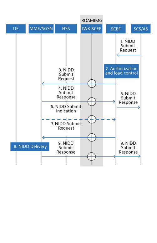
SCS/ASSCEFIWK-SCEFMME/SGSNUE
1. NIDD Submit Request
8. NIDD Delivery
ROAMIMG
HSS
2. Authorization and load control
3. NIDDSubmit Request
4. NIDD Submit
Response5. NIDD Submit
Response6. NIDD Submit
Indication
7. NIDD Submit Request
9. NIDD Submit
Response
9. NIDD Submit
Response
Cate
gory
App
licat
ion
Exam
ple
Avai
labi
lity
UL
Ban
dwid
th
& D
ata
Size
DL
Dat
a Si
ze
Freq
uenc
y
Pow
er
Del
ay S
ensi
tivi
ty
Cove
rage
Automotive Connected Car
HIGH99.9%
HIGH10Mbps200bytes
HIGH200bytes
HIGHContinuous
LOW HIGH1ms
NORMAL
IndustrialControl
Switchon/off, device triggeredto send
HIGH99.999%
HIGH50Mbps0-20bytes 50% of cases requireUL response
HIGH20bytes
MED1 day (40%)2hrs (40%)1 hour (15%)30mins (5%)
LOW HIGH1ms
DEEP
Utilities/Meters
SmartWaterMeter
LOW99%
LOW50kbps20bytes with cut off of 200 bytes
LOW50% of UL data size
MED1 day (40%)2hrs (40%)1 hour (15%)30mins (5%)
HIGH10yrs&4800mAH
LOW5sec
DEEP
Security Smoke alarm detectors, power failure otification, tamper notifications
HIGH99.9%
LOW50kbps20bytes
LOW0 ACK payload size is assumed to be 0bytes
LOWEvery few months, Every Year
LOW MED1sec
DEEP
5G Field Validation
5G Assuranceand Optimization
New 5G FeaturesDevelopment
5G Field Deployment and Sites Turn Up
5G Scaling UP
5G Lab SystemVerification