22
OEM'S SLIMLINE BETWEEN THE GLASS BLINDS September 1, 2015 SL20C-LIFT AND TILT SL20A- TILT ONLY

OEM'S SLIMLINE BETWEEN THE GLASS BLINDS
September 1, 2015 SL20C-LIFT AND TILT
SL20A- TILT ONLY

NOTICE
The side guides mentioned in this booklet are optional.
Table of Contents
Section I - SL20C - Pages 1- 5
Section II - SL20A Pages 6-10
Section III - Drawings, Operator Option Drawings Pages 11-15
Section IV - Glass Thickness/Magnet Speed Charts Pages 16-19
Section V - Order Form Pages 20

Section I - SL20C Specifications
OEM'S SLIMLINE SL20C INTERNAL GLASS BLIND SYSTEM
Description
A unique patented magnetically coupled gear driven lift and tilt mini-blind for installation in sealed insulated glass or replaceable glass packages. An externally mounted magnet controls the blind with integral cord loop held in place by a loop tensioner. The cord loop rotates the external magnet, which drives an internal magnet with which it is coupled. Moving the cord loop down on the right or left side of the outer magnet assembly will respectively raise or lower the blind. If the cord on the opposite side is moved after a raise or lower motion slat rotation will occur and then movement in the opposite direction.
O E M between the glass (BTG) mini-blinds when installed in an insulated glass (IG) package can be used in door window, regular window and office partition applications. The blinds offer convenient light level and privacy by tilting the slats to your preference or lifting them for a direct view. Gone is the need to periodically dust the blinds. The outer glass surface can be easily wiped and sanitized without affecting the blind. Since they are internally mounted, damage to the blinds from everyday use is avoided.
Definition of Blind
Requires a 0.750" internal glass airspace. Slat is aluminum alloy 6010-T8, size 12.5mm (.500") x .008" painted with low emissivity paint with a polyester Ultra Violet high resistant finish. Head rail and bottom rail profiles are 6063-T5 alloy painted in coordinated color with the slat. Also, high temperature plastics are provided. The ladder tape and the lift cord are thermally fixed polyester and U V resistant. The sintered neodymium, iron-born magnets have a produced energy of Bh max - 33 to 35 Mega Oersteds and a max working temperature of 248°F. The internal mechanism has steel gears hardened on the surface and bearings to reduce friction and support the magnets.
• Optional Accessories : side tracks for mounting the blind inside the glass package. These provide spacing between the traveling rail and inside surface of the interior pane of glass (low e coating protection). Holes are drilled in the sidetracks to allow inner glass package volume to access spacer bar desiccating material. Double-sided tape is affixed to the sidetracks, which enables adhesion to the side spacer bar.
® Options Include: Magnet operator location - top left or top right side Magnet wand - magnet operator with acrylic wand. (See Section III - Drawing 4). Knob Handle - Method for raising and lowering. (See Section III - Drawing 5). Magnet speed - standard. Cord length - 12, 20, 40, 60 inches. (See Section III - Drawing 1). Custom sizes must be placed with order. Colors - 6 colors: White 0102, Off-white 0125, Almond 0149, Tan 0069, Silver 0157, Gold 3000 Spacer bar for headrail
• Glass Package (IG) Supplier Scope: Maintain %" air gap for blind operation, ensure width and height rectangular internal glass dimensions, install sidetracks and blind into IG package consisting of glass, box spacer, corner keys and sealant (provided by IG supplier). When installing the blind and sidetracks, the top and side spacer bars must be clean and free of desiccant dust. The side spacer breather holes (if required) must be offset from the sidetrack tape for optimum internal moisture absorption. Identify materials and fabrication process to O E M to ensure compatibility with blind.
Ensure IG or replaceable glass package maintains the internal geometry necessary to allow blind to travel and slat rotation during environmental temperature and pressure excursions. Glass deflection
1
(internal bending) must be limited to Omm maximum to allow proper blind operation. Possible methods to achieve acceptable air gap include pressurization and/or the installation of capillary tubes.
Allowance also must be made for a slight ladder tape bunching effect as the blind is raised and the slat and ladder tape accumulate above the traveling rail. Optimum performance is obtained when a consistent VA" internal air gap is maintained.
The blind must be installed in the vertical position for proper raise/lower operation and slat tilt.
Blind Characteristics
Pulling the cord in the right side lowers the blind. When initially pulling this side the slat will rotate closed with the slat crown facing outside. Pulling the cord on the left side raises the blind. When initially pulling this side the slat will rotate closed with the slat crown facing the inside. Small adjustments by pulling on the right and left side of the cord will enable optimum slat positioning. The force to lift the blind is 36 Newtons maximum and to tilt is less than 10 Newtons.
The speed operation of the blinds will be different for the 3-magnet/gearing styles. Indentified below is information concerning movement of the external cord to raise the blind from 1mm or complete the total slat titling procedure.
System External Cord Movement Internal Blind Raising
Standard (direct) 7.5mm 1mm
Production Charts
The charts at the end of this section show operating range (width and height, outside glass dimensions) of blind for 3 magnet speeds and glass thickness form 1/8" to 1/4". Considering a 3/ 4" air space, the minimum overall glass package thickness is 1 inch using 2 1/8" thick glass pieces.
The charts identify, for each glass thickness, the calculated maximum tension (blind weight) until slipping (loss of coupling) of the magnets occurs. A safety factor of 2.2 times the calculated weight is utilized to develop the charts. The right hand side of charts show the limit of proper blind operation as the height and width (total weight) increase. The left hand side of charts show the height limitation as width decreases due to limits of cord wrapping around a horizontally moving lift tube.
Pricing and Delivery
The attached charts show blind pricing for various widths and heights as measured by outside glass dimensions.
Delivery is usually 3 weeks from receipt of order for all sizes. Contact O E M for delivery information.
Tolerances
• Size of blind is typically glass size less 7/8 inch for both width and height. This cutback is derived as follows and applies to both width and height. Spacer bar width 5/16 inch (quantity of 2) and sealant of 1/8 inch (both sides) for a total of 14/16 = 7/8 inch. The spacer bar must have a thickness of 3A inch to maintain air gap. Side tracks (if supplied) will be cut to internal pocket height less an allowance for head rail dimension. For other spacer bar dimensions, contact O E M to ensure proper blind sizing.
• Height of cord loop is +3/8 in/-3/4in. • A space of approximately 1/8" is left on each side between slats and spacer, for a free movement of the
system and to allow thermal transmission of the aluminum slats. © The production tolerance is +0/-1/16 for the width of the blind. The tolerance for the height of the
blind is +3/8in/-0; consequently the traveling (bottom) will sit on the lower spacer bar when completely lowered.
2

• As a result of an addition of tolerances of the lift cord and the internal wrapping mechanisms, it is possible to have a small inclination of the bottom rail while raising the blind. This will be more prevalent for narrow and very long blinds.
• The maximum tolerance for parallelism between the top rail and traveling rail of the blind is 5/16 inch.
Ordering Information
It is important to be precise when ordering. The following information must be provided - see order form.
• Colors: - 6 colors - White 0102, Off-white 0125, Almond 0149, Tan 0069, Silver 0157, Gold 3000 • Outside glass size (width and height) • Operator location (left or right) • Operator type (select from options in Section III) • Cord loop length (select from standard sizes or specify custom length) • Spacer bar utilized, sealant thickness, sightline deduction • Breather holes in sidetracks (yes or no) • Sidetrack
Confirmation and Tests
Testing has been performed by the following European Institutes: Rosenheim, Istitito Giordano and CSTB. These tests concern the optical characteristics of the blinds, energy reflection and absorption of double -glazing units with an installed blind and the hermetic sealing of units to minimize condensation (fogging) for increased life cycle performance. The blinds have completed A S T M E 774-97 testing in IG units for durability classification by the Insulating Glass Certification Council. Life cycle testing demonstrating over 10,000 raise and lower operations has been completed. Proper blind operation inside and IG unit has been demonstrated with the inside glass exposed to a temperature of 20°C and the external glass exposed to a temperature of -30°.
Installation Instructions SL20C with Side Guides
Ensure the wings of the sideguides are on the same side as the head rail magnet mechanism. The magnet must be separated from the inside of the glass to allow unimpeded ability to rotate.
• General information - work place clean and free from dust, handle blinds with care and cleanliness, do not contact the slats with sealant
• Receipt checking - check the blind package for no damage, ensure all components are available, verify correct size
Summary of production steps (other alternative possible based on IG production techniques):
Assemble the spacer bars; ensure moisture absorbent material (such as desiccant) is loaded into the spacer bar. The desiccant will absorb moisture and eliminate the possible condensation (fogging) inside the glass package.
Position the spacer bar assembly on one side of the glass. Seal in an appropriate manner, avoiding potential contact between butyl and blind when installed. Ensure glass is not bent or bowing inward. While positioning the spacer bars on the glass be sure of their perfect parallelism (bent spacers would stop movement of the blind). The wing of the side guide must be turned on magnet's side. For low-e glasses avoid rubbing the blind on the glass or damage while handling. Position the blind inside the spacer bar, preferably at the lower side. Install sidetracks as shown on the drawings. After ensuring side spacer is clean and free of desiccant dust or oils, press the sidetracks firmly against side spacer for good adhesive. Install the second pane of glass over the blind/side track and spacer bar. Ensure glass is flat and does not bend inward to impede blind operation.
Ensure a 3A" air gap and proper width and height of the package. Some techniques to be considered to maintain air gap are capillary tubes (pressure equalization) and a slight internal pressurization. IG producer to establish proper technique.
3

Seal the second pane of glass to the spacer bar.
• Checks Position the double-glazing in a vertical position and check for parallelism of the glasses. Check for visual defects. Test the blind for operation using the external magnet. Raise the blind prior to moving the double-glazing unit.
• Transport Use special trolleys to position the unit vertically and with the blind on the lower side or side part.
INSTALLATION INSTRUCTIONS FOR THE SL20C LIFT & TILT BLIND WITHOUT SIDE GUIDES
1. With the box spacer channels pre-assembled and the blind slats completely in the raised position, attach the blind headrail to the spacer bar corner keys. You may want to have the entire assembly turned upside-down to let gravity assist.
2. Attach the two panels of glass to each side of the package making sure the channels are square and evenly spaced with the edge of the glass. Apply sealant around the edge of the entire package.
3. Remove the adhesive strip for the outer magnet assembly and attach to operate.
SL20C BLIND WITH INTERCEPT WITHOUT SIDE GUIDES
Installation Instructions
1. Assemble intercept spacer for required dimensions.
2. Insert intercept clips ever six inches along top of spacer system. Turn clips to lock into place.
3. Insert intercept covers down both sides of the intercept making sure the cover is snapped into the intercept system. You may also install the cover into the bottom of your system for a finished look.
4. The blind is now ready to be sealed. It is critical that the %" inside air space is maintained to insure proper blind operation.
5. Once sealed, the outer operator can be installed.
6. Clean glass surface, remove adhesive strips and apply to the glass making sure the operator is aligned with the internal operator.
4

Final Installation
Check the shape of the glass ensuring the 3A inch air gap. If the internals are pressurized slightly, close off the supply and seal the unit after verifying free movement of the internal blind. Ensure the unit is positioned vertically for this check.
If the external magnetic operator with cord and tensioner are to be installed at this time follow the steps below:
Provide necessary space around the internal magnet to interface with the external magnet.
Position the external magnet after carefully cleaning the glass area where it will be placed. For proper operation, the external magnet must be perfectly interfaced with the internal one. Therefore, before removing the adhesive protecting film, position the external magnet on the glass next to the internal one. Verify smooth raising and lowering of the blind. Then remove the film and position the external magnet on the glass following the magnetic attraction.
Position the cord tensioner, keeping the cord in tension. The operator tip on the cord tensioner should be positioned at approximately the line on the tensioner or slightly higher to keep the cord engaged. Excessive tension on the loop will hinder cord movement.
The right cord lowers the blind and the left cord raises it. The movement of the external cord will have to be uniform: strong pulling on the cord could damage the internal blind components, especially as the blind reaches the fully raised or lowered position.
Operation
The Venetian blind regulates the amount of internal light and allows darkening in the case of strong luminosity. Darkness will not be total since the ladder tape separates the slats and the slats contain holes to allow for passage of the lift cords. A side space must also be provided to allow free raise/lower movement of the system and thermal dissipation of the aluminum slats. This space also allows for assembly tolerances inside the double-glazing.
Venetian blind manuals do not give corner closure values of the slats. They indicate, in the case of a closed blind, that an external observer outside the house watching in parallel inside through the closed Venetian blind must not see any object inside.
In consideration for child safety requirements, a generic warning hangtag and/or operational hangtag will be attached to the cord loop.
Warranty
• Blind repair or replacement only:
10 years when not exposed to greater than 220°F
• Outer cord loop - 1 year
• Failure to install cord tensioner voids all warranties (a tensioner will be supplied with each blind)
Low - E glass is not recommended with blinds that raise and lower. The ladder tape stacks can possibly touch the coating on the glass surface and with time, the constant friction can wear on the coating. If Low - E glass must be used, use a hard coat Low-E (pyrolitic) along with side guides. Note this does not guarantee there will be no contact between the low - E glass surface and the blind.
There will be less chance of contact between the blind and the Low E glass surface by using tilt only blinds.
5

Section II - SL20A Specifications
OEM's SLIMLINE SL20A INTERNAL GLASS BLIND SYSTEM
Description
A unique patented magnetically coupled gear driven tilt mini-blind for installation in sealed insulated glass or replaceable glass packages. An externally mounted magnet assembly controls the blind with either a knob or wand. The operator rotates the external magnet, which drives an internal magnet with which it is coupled.
O E M between the glass (BTG) mini-blinds when installed in an insulated glass (IG) package can be used in door window, regular window and office partition applications. The blinds offer convenient light level and privacy by tilting the slats to your preference. Gone is the need to periodically dust the blinds. The outer glass surface can be easily wiped and sanitized without affecting the blind. Since they are internally mounted, damage to the blinds from everyday use is avoided.
Definition of Blind
Requires a 0.750" internal glass airspace. Slat is aluminum alloy 6010-T8, size 12.5mm (.500") x .008" painted with low emissivity paint with a polyester Ultra Violet high resistant finish. Head rail and bottom rail profiles are 6063-T5 alloy painted in coordinated color with the slat. Also, high temperature plastics are provided. The ladder tape and plisse cord are thermally fixed polyester and U V resistant. The sintered neodymium, iron-boron magnets have a produced energy of Bh max - 33 to 35 Mega Oesteds and a max working temperature of 248°F. The internal mechanism has steel gears hardened on the surface and bearings to reduce friction and support the magnets.
• Optional Accessories: sidetracks for mounting the blind inside the glass package. These provide spacing between the blind and inside surface of the interior pane of glass (low e coating protection). Holes are drilled in the sidetracks to allow inner glass package volume to access spacer bar desiccating material. Double-sided tape is affixed to the sidetracks, which also enables adhesion to the side spacer bars. Pins are located at the bottom of sidetracks that engage into holes on the sides of the bottom rail. This configuration holds the bottom rail in position.
• Options Include: Magnet operator location - left or right side Magnet speed - standard. Cord length - 12, 20, 40, 60 inches Color - 6 colors: White 0102, Off-white 0125, Almond 0149, Tan 0069, Silver 0157, Gold 3000 Magnet wand - magnet operator with acrylic wand (See Section III - Drawing 4). Knob handle - knob method of tilting (See Section III - Drawing 5). Spacer bar for headrail
• Glass Package (IG) Supplier Scope: Maintain 3A" air gap for blind operation, ensure width and height rectangular internal glass dimensions, install sidetracks and blind into IG package consisting of glass, box spacer, corner keys and sealant (provided by IG supplier). When installing the blind and sidetracks, the top and side spacer bars must be clean and free of desiccant dust. The side spacer breather hole(s) (if required) must be offset from the sidetrack tape for optimum internal moisture absorption. Identify materials and fabrication process to O E M to ensure compatibility with blind.
Ensure IG or replaceable glass package maintains the internal geometry necessary to allow slat rotation during environmental temperature and pressure excursions. Glass deflection (internal bending) must be limited to 0mm maximum to allow proper blind operation. Possible methods to relieve acceptable air gap include pressurization and/or the installation of capillary tubes.
The blind must be installed in the vertical position for proper slat tilt. The sidetrack bottom pins must engage the holes in the ends of the bottom rail.
6
Blind Characteristics
Pulling the cord in the right side tilts the blind. When initially pulling this side the slat will rotate closed with the slat crown facing outside. When initially pulling the left side the slat will rotate closed with the slat crown facing the inside. Small adjustments by pulling on the right and left side of the cord will enable optimum slat positioning. The force to tilt the blind is less than 10 Newtons.
Production Charts
The chart in Section III shows available/producible operating range (width and height, outside glass dimensions) of blind for glass thickness from .125" (1/8") to .250". Considering a 3/ 4" air space, the minimum overall glass package thickness is 1 inch using 2 1/8" thick glass pieces.
The chart identifies, for the glass thickness range, the calculated maximum tension (blind weight) until slipping (loss of coupling) of the magnets occurs. A safety factor of 2.2 times the calculated weight is utilized to develop the charts.
Pricing and Delivery
The attached chart shows blind pricing for various widths and heights as measured by outside glass dimensions. Sizes beyond the identified range are not available.
Delivery is usually 3 weeks from receipt of order for all sizes.
Tolerances
• Size of blind is typically glass size less 7/8 inch for both width and height. This cutback is derived as follows and applies to both width and height. Spacer bar width 5/16 inch (quantity of 2) and sealant of 1/8 inch (both sides) for total of 14/16 = 7/8 inch. The spacer bar must have a thickness of 3A inch to maintain air gap. Sidetracks (if supplied) by O E M will be cut to internal pocket height less an allowance.
• For head rail dimension and for other spacer bar dimensions, contact O E M to ensure proper blind sizing.
• Height of cord loop is +3/8in, -3/4 in • A space of approximately 1/8" is left each side between slats and spacer for a free movement of the
system and to allow thermal transmission of the aluminum slats. • The production tolerance is +0/-1/16 for the width of the blind. The tolerance for the height of the
blind is +3/8in/-0, consequently the bottom rail will engage the pins in the sidetrack with some slack and be slightly above the lower spacer bar.
Ordering Information
It is important to be precise when ordering. The following information must be provided. • Colors - 6 colors: White 0102, Off-white 0125, Almond 0149, Tan 0069, Silver 0157, Gold 3000 • Outside glass size (width and height) • Operator location (left or right) ® Operator type (select from options in Section III) • Cord loop length (select from standard sizes) • Magnet speed (standard) • Spacer bar utilized, sealant thickness (initial order) ® Internal glass used (Low-e); (initial order) • Side tracks provided (yes or no); (initial order) • Order form (Section V)
7

Confirmation and Tests
Testing has been performed by the following European Institutes: Rosenheim, Istitito Giordano and CSTB. These tests concern the optical characteristics of the blinds, energy reflection and absorption of double -glazing units with an installed blind and the hermetic sealing of units to minimize condensation (fogging) for increased life cycle performance. The blinds have completed A S T M E 774-97 testing in IG units for durability classification by the Insulating Glass Certification Council. Life cycle testing demonstrating over 10,000 tilting operations has been completed. Proper blind operation inside and IG unit has been demonstrated with the inside glass exposed to a temperature of 20°C and the external glass exposed to a temperature of -30°.
Installation Instructions SL2QA with Side Guides
Ensure the wings of the sidetracks are on the same side as the head rail magnet mechanism. The magnet must be separated from the inside of the glass to allow unimpeded ability to rotate.
• General information - work place clean and free from dust, handle blinds with care and cleanliness, do not contact the slats with sealant
• Receipt checking - check the blind package for no damage, ensure all components are available, verify correct size
Summary of production steps (other alternative possible based on IG production techniques):
Assemble the spacer bars; ensure moisture absorbent material (such as desiccant) is loaded into the spacer bar. The desiccant will absorb moisture and eliminate the possible condensation (fogging) inside the glass package.
Position the spacer bar assembly on one side of the glass. Seal in an appropriate manner, avoiding potential contact between butyl and blind when installed. Ensure glass is not bent or bowing inward. While positioning the spacer bars on the glass be sure of their perfect parallelism (bent spacers would stop movement of the blind). The wing of the side guide must be turned on magnet's side. For low-e glasses avoid rubbing the blind on the glass or damage while handling.
Position the blind inside the spacer bar, preferably at the lower side. Install sidetracks as shown on the drawings. After ensuring side spacer is clean and free of desiccant dust or oils, press the sidetracks firmly against side spacer for good adhesive. Install the second pane of glass over the blind/side track and spacer bar. Ensure glass is flat and does not bend inward to impede blind operation.
Ensure a V*" air gap and proper width and height of the package. Some techniques to be considered to maintain air gap are capillary tubes (pressure equalization) and a slight internal pressurization. IG producer to establish proper technique.
Seal the second pane of glass to the spacer bar.
• Checks Position the double-glazing in a vertical position and check for parallelism of the glasses. Check for visual defects. Test the blind for operation using the external magnet. Raise the blind prior to moving the double-glazing unit.
• Transport Use special trolleys to position the unit vertically and with the blind on the lower side or side part.
8
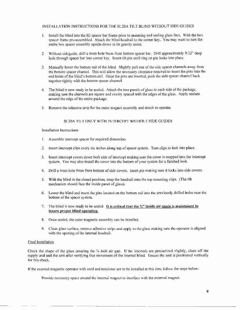
INSTALLATION INSTRUCTIONS FOR THE SL20A TILT BLIND WITHOUT SIDE GUIDES
1. Install the blind into the IG spacer bar frame prior to mounting and sealing glass lites. With the box spacer frame pre-assembled. Attach the blind headrail to the corner key. You may want to turn the entire box spacer assembly upside-down to let gravity assist.
2. Without sideguide, drill a 4mm hole 9mm from bottom spacer bar. Drill approximately 9/32" deep hole through spacer bar into corner key. Insert tilt pin until ring on pin locks into place.
3. Manually lower the bottom rail of the blind. Slightly pull one of the side spacer channels away from the bottom spacer channel. This will allow the necessary clearance required to insert the pins into the end holes of the blind's bottom rail. Once the pins are inserted, push the side spacer channel back together tightly with the bottom spacer channel.
4. The blind is now ready to be sealed. Attach the two panels of glass to each side of the package, making sure the channels are square and evenly spaced with the edges of the glass. Apply sealant around the edge of the entire package.
5. Remove the adhesive strip for the outer magnet assembly and attach to operate.
SL20A TILT O N L Y WITH INTERCEPT WITHOUT SIDE GUIDES
Installation Instructions
1. Assemble intercept spacer for required dimension.
2. Insert intercept clips every six inches along top of spacer system. Turn clips to lock into place.
3. Insert intercept covers down both side of intercept making sure the cover is snapped into the intercept system. You may also install the cover into the bottom of your system for a finished look.
4. Drill a 4mm hole 9mm from bottom of side covers. Insert pin making sure it locks into side covers.
5. With the blind in the closed position, snap the headrail onto the top mounting clips. (The tilt mechanism should face the inside panel of glass).
6. Lower the blind and insert the pins located on the bottom rail into the previously drilled holes near the bottom of the spacer system.
7. The blind is now ready to be sealed. It is critical that the V" inside air space is maintained to insure proper blind operation.
8. Once sealed, the outer magnetic assembly can be installed.
9. Clean glass surface, remove adhesive strips and apply to the glass making sure the operator is aligned with the opening of the internal headrail.
Final Installation
Check the shape of the glass ensuring the 3A inch air gap. If the internals are pressurized slightly, close off the supply and seal the unit after verifying free movement of the internal blind. Ensure the unit is positioned vertically for this check.
If the external magnetic operator with cord and tensioner are to be installed at this time follow the steps below:
Provide necessary space around the internal magnet to interface with the external magnet.
9

Position the external magnet after carefully cleaning the glass area where it will be placed. For proper operation, the external magnet must be perfectly interfaced with the internal one. Therefore, before removing the adhesive protecting film, position the external magnet on the glass next to the internal one. Verify smooth slat rotation of the blind. Then remove the film and position the external magnet on the glass following the magnetic attraction.
Position the cord tensioner, keeping the cord in tension. The operator tip on the cord tensioner should be positioned at approximately the line on the tensioner or slightly higher to keep the cord engaged. Excessive tension on the loop will hinder cord movement.
The right cord tilts the blind crown outward and the left cord tilts the crown inward. The movement of the external cord will have to be uniform: strong pulling on the cord could damage the internal blind components.
Operation
The Venetian blind regulates the amount of internal light and allows darkening in the case of strong luminosity. Darkness will not be total since the ladder tape separates the slats and the slats contain holes to allow for passage of the lift cords. A side space must also be provided to allow free tilting movement of the system and thermal dissipation of the aluminum slats. This space also allows for assembly tolerances inside the double-glazing.
Venetian blind manuals do not give corner closure values of the slats. They indicate, in the case of a closed blind, that an external observer outside the house watching in parallel inside through the closed Venetian blind must not see any object inside.
In consideration for child safety requirements, a generic warning hangtag and/or operational hangtag will be attached to the cord loop.
Warranty
• Blind repair or replacement only: 10 years when not exposed to greater than 220°F
• Outer cord loop - 1 year
• Failure to install cord tensioner voids all warranties (a tensioner will be supplied with each blind if cord operator is used. A l l SL20A blinds will normally use a wand or knob operator. Therefore, a cord tensioner is not required).
Low - E glass is not recommended with blinds that raise and lower. The ladder tape stacks can possibly touch the coating on the glass surface and with time, the constant friction can wear on the coating. If Low - E glass must be used, use a hard coat Low-E (pyrolitic) along with side guides. Note this does not guarantee there will be no contact between the low - E glass surface and the blind.
There will be less chance of contact between the blind and the Low E glass surface by using tilt only blinds.
10

SL20C Drawing
SL20A Drawing
Wand/loop External Control Assembly
Wand External Control Assembly
Knob External Control Assembly

1.418"-
0.982"-
Lift and Tilt Cordloop Operator
- r
1.260"- FRONT VIEW
y /
/
/
/
/
/
/
/
/
/
/
/
/
/
/
/
/
/
ni
i
Lz SIDE VIEW
0.732'
2.870'
2.532'
0.685'
B
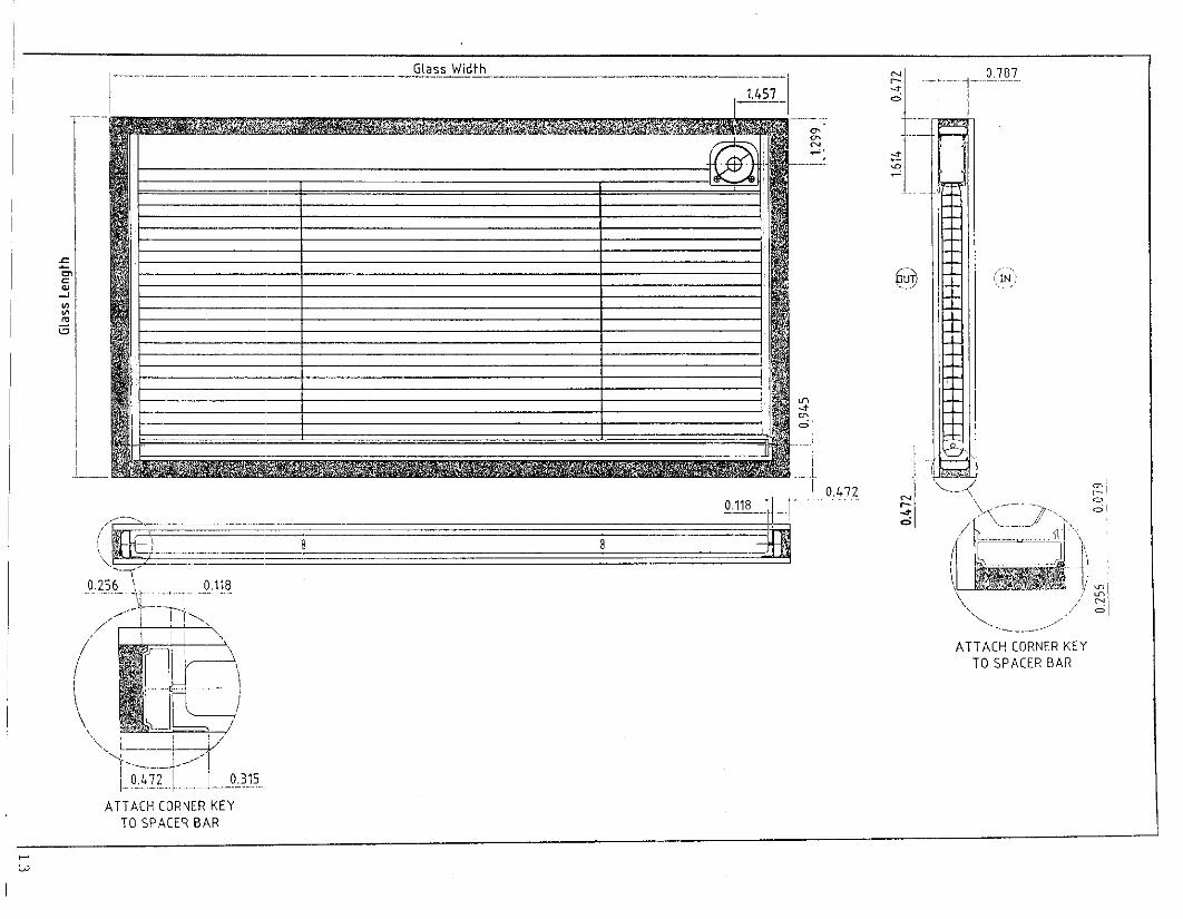
A T T A C H CORNER K E Y
TO S P A C E R B A R
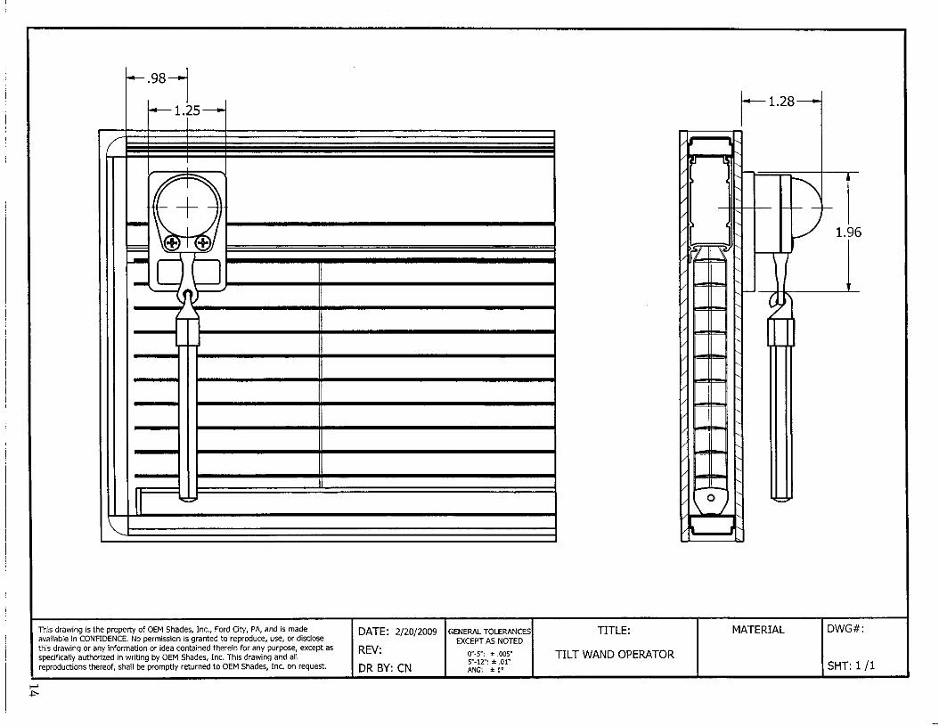
1.96
This drawing is the property of OEM Shades, Inc., Ford City, PA, and is made available in CONFIDENCE. No permission is granted to reproduce, use, or disclose this drawing or any information or idea contained therein for any purpose, except as specifically authorized in writing by OEM Shades, Inc. This drawing and all reproductions thereof, shall be promptly returned to OEM Shades, Inc. on request.
DATE: 2/20/2009
REV:
DR BY: CN
GENERAL TOLERANCES EXCEPT AS NOTED
0"-5": ± .005" 5"-12": ± .01" ANG: ± 1°
TITLE:
TILT WAND OPERATOR
MATERIAL DWG#:
SHT: 1II

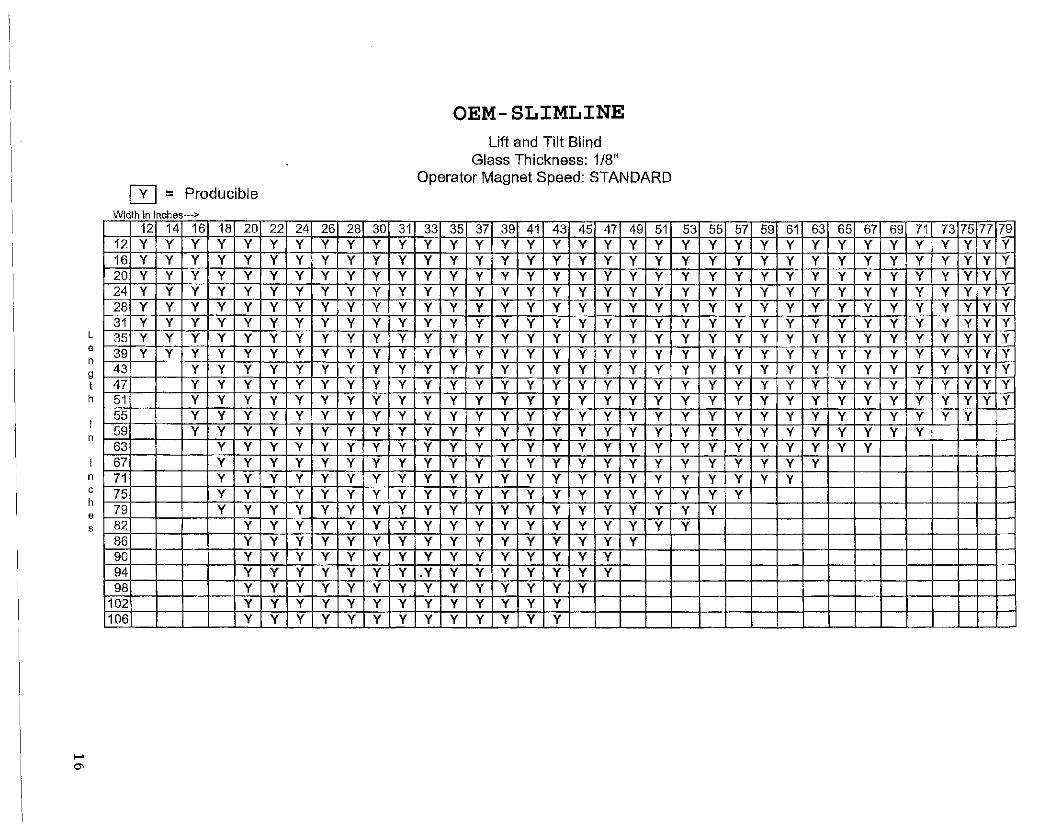
OEM-SLIMLINE Lift and Tilt Blind
Glass Thickness: 1/8" Operator Magnet Speed: STANDARD
fT] • Producible Width In Inches—>
h
12 14 16 18 20 22 24 26 28 30 31 33 35 37 39 41 43 45 47 49 51 53 55 57 59 61 63 65 67 69 71 73 75 77 79 12 Y Y Y Y Y Y Y Y Y Y Y Y Y Y Y Y Y Y Y Y Y Y Y Y Y Y Y Y Y Y Y Y Y Y Y 16 Y Y Y Y Y Y Y Y Y Y Y Y Y Y Y Y Y Y Y Y Y Y Y Y Y Y Y Y Y Y Y Y Y Y Y 20 Y Y Y Y Y Y Y Y Y Y Y Y Y Y Y Y Y Y Y Y Y Y Y Y Y Y Y Y Y Y Y Y Y Y Y 24 Y Y Y Y Y Y Y Y Y Y Y Y Y Y Y Y Y Y Y Y Y Y Y Y Y Y Y Y Y Y Y Y Y Y Y 28 Y Y Y Y Y Y Y Y Y Y Y Y Y Y Y Y Y Y Y Y Y Y Y Y Y Y Y Y Y Y Y Y Y Y Y 31 Y Y Y Y Y Y Y Y Y Y Y Y Y Y Y Y Y Y Y Y Y Y Y Y Y Y Y Y Y Y Y Y Y Y Y 35 Y Y Y Y Y Y Y Y Y Y Y Y Y Y Y Y Y Y Y Y Y Y Y Y Y Y Y Y Y Y Y Y Y Y Y 39 Y Y Y Y Y Y Y Y Y Y Y Y Y Y Y Y Y Y Y Y Y Y Y Y Y Y Y Y Y Y Y Y Y Y Y 43 Y Y Y Y Y Y Y Y Y Y Y Y Y Y Y Y Y Y Y Y Y Y Y Y Y Y •Y Y Y Y Y Y Y 47 Y Y Y Y Y Y Y Y Y Y Y Y Y Y Y Y Y Y Y Y Y Y Y Y Y Y Y Y Y Y Y Y Y 51 Y Y Y Y Y Y Y Y Y Y Y Y Y Y Y Y Y Y Y Y Y Y Y Y Y Y Y Y Y Y Y Y Y 55 Y Y Y Y Y Y Y Y Y Y Y Y Y Y Y Y Y Y Y Y Y Y Y Y Y Y Y Y Y Y Y 59 Y Y Y Y Y Y Y Y Y Y Y Y Y Y Y Y Y Y Y Y Y Y Y Y Y Y Y Y Y 63 Y Y Y Y Y Y Y Y Y Y Y Y Y Y Y Y Y Y Y Y Y Y Y Y Y Y 67 Y Y Y Y Y Y Y Y Y Y Y Y Y Y Y Y Y Y Y Y Y Y Y Y 71 Y Y Y Y Y Y Y Y Y Y Y Y Y Y Y Y Y Y Y Y Y Y Y 75 Y Y Y Y Y Y Y Y Y Y Y Y Y Y Y Y Y Y Y Y Y 79 Y Y Y Y Y Y Y Y Y Y Y Y Y Y Y Y Y Y Y Y 82 Y Y Y Y Y Y Y Y Y Y Y Y Y Y Y Y Y Y 86 Y Y Y Y Y Y Y Y Y Y Y Y Y Y Y Y 90 Y Y Y Y Y Y Y Y Y Y Y Y Y Y Y 94 Y Y Y Y Y Y Y .Y Y Y Y Y Y Y Y 98 Y Y Y Y Y Y Y Y Y Y Y Y Y Y
102 Y Y Y Y Y Y Y Y Y Y Y Y Y 106 Y Y Y Y Y Y Y Y Y Y Y Y Y
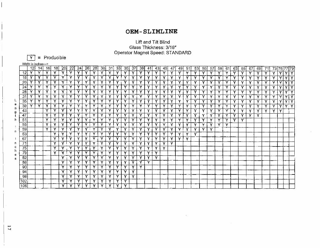
OEM-SLIMLINE Lift and Tilt Blind
Glass Thickness: 3/16" Operator Magnet Speed; STANDARD
] Y [ = Producible Width In inches—>
h
12 14 16 18 20 22 24 26 28 30 31 33 35 37 39 41 43 45 47 49 51 53 55 57 59 61 63 65 67 69 71 73 75 77 79 12 Y Y Y Y Y Y Y Y Y Y Y Y Y Y Y Y Y Y Y Y Y Y Y Y Y Y Y Y Y Y Y Y Y Y Y 16 Y Y Y Y Y Y Y Y Y Y Y Y Y Y Y Y Y Y Y Y Y Y Y Y Y Y Y Y Y Y Y Y Y Y Y 20 Y Y Y Y Y Y Y Y Y Y Y Y Y Y Y Y Y Y Y Y Y Y Y Y Y Y Y Y Y Y Y Y Y Y Y 24 Y Y Y Y Y Y Y Y Y Y Y Y Y Y Y Y Y Y Y Y Y Y Y Y Y Y Y Y Y Y Y Y Y Y Y 28 Y Y Y Y Y Y Y Y Y Y Y Y Y Y Y Y Y Y Y Y Y Y Y Y Y Y Y Y Y Y Y Y Y Y Y 31 Y Y Y Y Y Y Y Y Y Y Y Y Y Y Y Y Y Y Y Y Y Y Y Y Y Y Y Y Y Y Y Y Y Y Y 35 Y Y Y Y Y Y Y Y Y Y Y Y Y Y Y Y Y Y Y Y Y Y Y Y Y Y Y Y Y Y Y Y Y Y Y 39 Y Y Y Y Y Y Y Y Y Y Y Y Y Y Y Y Y Y Y Y Y Y Y Y Y Y Y Y Y Y Y Y Y Y Y 43 Y Y Y Y Y Y Y Y Y Y Y Y Y Y Y Y Y Y Y Y Y Y Y Y Y Y Y Y Y Y Y 47 Y Y Y Y Y Y Y Y Y Y Y Y Y Y Y Y Y Y Y Y Y Y Y Y Y Y Y Y 51 Y Y Y Y Y Y Y Y Y Y Y Y Y Y Y Y Y Y Y Y Y Y Y Y Y Y 55 Y Y Y Y Y Y Y Y Y Y Y Y Y Y Y Y Y Y Y Y Y Y Y Y 59 Y Y Y Y Y Y Y Y Y Y Y Y Y Y Y Y Y Y Y Y Y Y 63 Y Y Y Y Y Y Y Y Y Y Y Y Y Y Y Y Y Y Y 67 Y Y Y Y Y Y Y Y Y Y Y Y Y Y Y Y Y Y 71 Y Y Y Y Y Y Y Y Y Y Y Y Y Y Y Y 75 Y Y Y Y Y Y Y Y Y Y Y Y Y Y Y 79 Y Y Y Y Y Y Y Y Y Y Y Y Y Y 82 Y Y Y Y Y Y Y Y Y Y Y Y Y 86 Y Y Y Y Y Y Y Y Y Y Y Y 90 Y Y Y Y Y Y Y Y Y Y Y 94 Y Y Y Y Y Y Y Y Y Y 98 Y Y Y Y Y Y Y Y Y Y
102 Y Y Y Y Y Y Y Y Y 106 Y Y Y Y Y Y Y Y Y
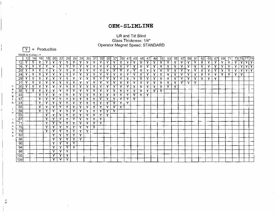
OEM-SLIMLINE Lift and Tilt Blind
Glass Thickness: 1/4" Operator Magnet Speed: STANDARD
[~Y~l = Producible Width In Inches—>
L
12 14 16 18 20 22 24 26 28 30 31 33 35 37 39 41 43 45 47 49 51 53 55 57 59 61 63 65 67 69 71 73 75 77 79 12 Y Y Y Y Y Y Y Y Y Y Y Y Y Y Y Y Y Y Y Y Y Y Y Y Y Y Y Y Y Y Y Y Y Y Y 16 Y Y Y Y Y Y Y Y Y Y Y Y Y Y Y Y Y Y Y Y Y Y Y Y Y Y Y Y Y Y Y Y Y Y Y 20 Y Y Y Y Y Y Y Y Y Y Y Y Y Y Y Y Y Y Y Y Y Y Y Y Y Y Y Y Y Y Y Y Y Y Y 24 Y Y Y Y Y Y Y Y Y Y Y Y Y Y Y Y Y Y Y Y Y Y Y Y Y Y Y Y Y Y Y Y Y 28 Y Y Y Y Y Y Y Y Y Y Y Y Y Y Y Y Y Y Y Y Y Y Y Y Y Y Y Y Y 31 Y Y Y Y Y Y Y Y Y Y Y Y Y Y Y Y Y Y Y Y Y Y Y Y Y Y 35 Y Y Y Y Y Y Y Y Y Y Y Y Y Y Y Y Y Y Y Y Y Y Y 39 Y Y Y Y Y Y Y Y Y Y Y Y Y Y Y Y Y Y Y Y Y 43 Y Y Y Y Y Y Y Y Y Y Y Y Y Y Y Y Y 47 Y Y Y Y Y Y Y Y Y Y Y Y Y Y Y 51 Y Y Y Y Y Y Y Y Y Y Y Y Y Y 55 Y Y Y Y Y Y Y Y Y Y Y Y Y 59 Y Y Y Y Y Y Y Y Y Y Y Y 63 Y Y Y Y Y Y Y Y Y Y 67 Y Y Y Y Y Y Y Y Y 71 Y Y Y Y Y Y Y Y Y 75 Y Y Y Y Y Y Y Y 79 Y Y Y Y Y Y Y 82 Y Y Y Y Y 86 Y Y Y Y Y 90 Y Y Y Y 94 Y Y Y Y 98 Y Y Y
102 Y Y Y 106 Y Y Y
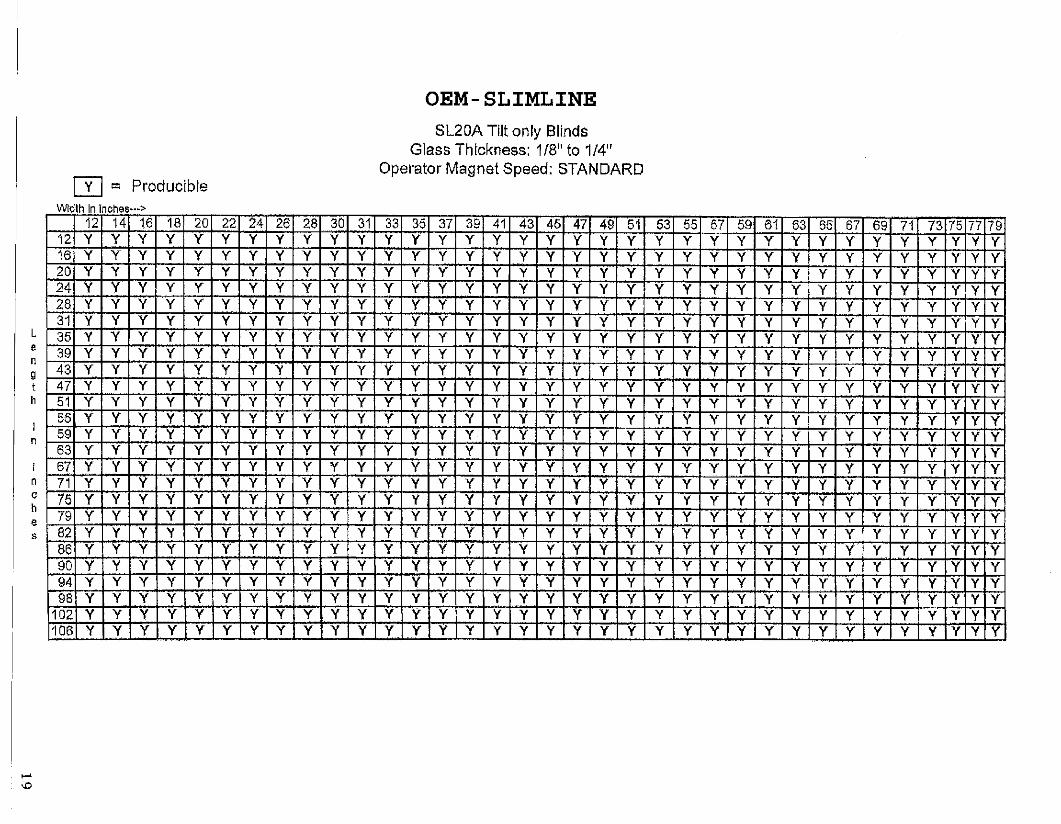
OEM-SLIMLINE SL20A Tilt only Blinds
Glass Thickness: 1/8" to 1/4" Operator Magnet Speed: STANDARD
fTl • Producible Width In Inches—>
12 14 16 18 20 22 24 26 28 30 31 33 35 37 39 41 43 45 47 49' 51 63 55 67 59 61 63 65 67 69 71 73 75 77 79 12 Y Y Y Y Y Y Y Y Y Y Y Y Y Y Y Y Y Y Y Y Y Y Y Y Y Y Y Y Y Y Y Y Y Y Y 16 Y Y Y Y Y Y Y Y Y Y Y Y Y Y Y Y Y Y Y Y Y Y Y Y Y Y Y Y Y Y Y Y Y Y Y 20 Y Y Y Y Y Y Y Y Y Y Y Y Y Y Y Y Y Y Y Y Y Y Y Y Y Y Y Y Y Y Y Y Y Y Y 24 ""?"" 7 Y Y Y Y Y Y Y Y Y Y Y Y Y Y Y Y Y Y Y Y Y Y Y Y Y Y Y Y Y Y Y Y Y 28 Y Y Y Y Y Y Y Y Y Y Y Y Y Y Y Y Y Y Y Y Y Y Y Y Y Y Y Y Y Y Y Y Y Y Y 31 Y Y Y Y Y Y Y Y Y Y Y Y Y Y Y Y Y Y Y Y Y Y Y Y Y Y Y Y Y Y Y Y Y Y Y 35 Y Y Y Y Y Y Y Y Y Y Y Y Y Y Y Y Y Y Y Y Y Y Y Y Y Y Y Y Y Y Y Y Y Y Y 39 Y Y Y Y Y Y Y Y Y Y Y Y Y Y Y Y'" Y Y Y Y Y Y Y Y Y Y Y Y Y Y Y Y Y Y Y 43 Y Y Y Y Y Y Y Y T Y Y Y Y Y Y Y Y Y Y Y Y Y Y Y Y Y Y Y Y Y Y Y Y Y Y 47 Y Y Y Y Y Y Y Y Y Y Y Y Y Y Y Y Y Y Y Y Y Y Y Y Y Y Y Y Y Y Y Y Y Y Y 51 Y Y Y Y Y Y Y Y Y Y Y Y Y Y Y Y Y Y Y Y Y Y Y Y Y Y Y Y Y Y Y Y Y Y Y 55 Y Y Y Y Y" Y Y Y Y Y Y Y Y Y Y Y Y Y Y Y Y Y Y Y Y Y Y Y Y Y Y Y Y Y Y 59 Y Y Y Y Y Y Y Y Y Y Y Y Y Y Y Y Y Y Y Y Y Y Y Y Y Y Y Y Y Y Y Y Y Y Y 63 Y Y Y Y Y Y Y Y Y Y Y Y Y Y Y Y Y Y Y Y Y Y Y Y Y Y Y Y Y Y Y Y Y Y Y 67 Y Y Y Y Y Y Y Y Y Y Y Y Y Y Y Y Y Y Y Y Y Y Y Y Y Y Y Y Y Y Y Y Y Y Y 71 Y Y Y Y Y Y Y Y Y Y Y Y Y Y Y Y Y Y Y Y Y Y Y Y Y Y Y Y Y Y Y Y Y Y Y 76 Y Y Y Y Y Y Y Y Y Y Y Y Y Y Y Y Y Y Y Y Y Y Y Y Y Y Y Y Y Y Y Y Y Y Y 79 Y Y Y Y Y Y Y Y Y Y Y Y Y Y Y Y Y Y Y Y Y Y Y Y Y Y Y Y Y Y Y Y Y Y Y 82 Y Y Y Y Y Y Y Y Y Y Y Y Y Y Y Y Y Y Y Y Y Y Y Y Y Y Y Y Y Y Y Y Y Y Y 86 Y Y V Y Y Y Y Y Y Y Y Y Y Y Y Y Y Y Y Y Y Y Y Y Y Y Y Y ""V Y Y Y Y Y Y 90 Y Y Y Y Y Y Y Y Y V Y Y Y Y Y Y Y Y Y Y Y Y Y Y Y Y Y Y Y Y Y Y Y Y 94 Y Y Y Y Y Y Y Y Y Y Y Y Y Y Y Y Y Y Y Y Y Y Y Y Y Y Y Y Y Y Y Y Y Y Y 98 Y Y Y Y Y " Y Y Y Y Y Y Y Y i Y " Y Y Y Y Y Y Y Y Y Y Y • y Y Y Y Y Y Y Y Y Y
102 Y Y Y Y Y Y Y Y Y Y Y Y Y Y Y Y Y Y Y Y Y Y Y Y Y Y Y Y Y Y Y Y Y V Y 106 Y Y Y Y Y Y Y Y Y Y Y Y Y Y Y Y Y Y Y Y Y Y Y Y Y Y Y Y Y Y Y Y Y V
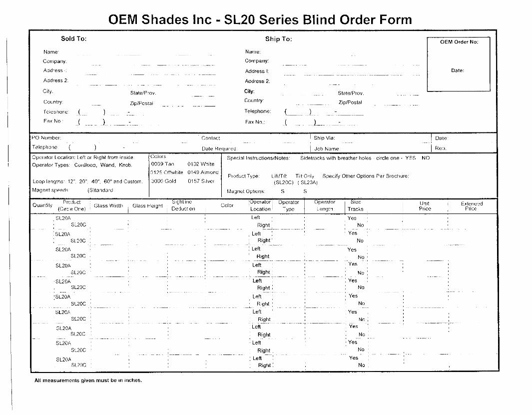
OEM Shades Inc - SL20 Series Blind Order Form Sold To: Ship To:
Name:
Company:
Address I:
Address 2:
City:
Country:
Telephone:
Fax No.:
State/Pro v.
Zip/Postal
Name:
Company:
Address I:
Address 2:
City:
Country:
Telephone:
Fax No.:
State/Prov.
Zip/Postal
OEM Order No:
Date:
PO Number:
Telephone: ( )
Contact:
Date Required:
Ship Via:
Job Name:
Date:
Rep:
Operator Location: Left or Right from inside. Operator Types: Corclloop, Wand, Knob.
Loop lengths: 12", 20". 40", 60" and Custom.
Magnet speeds: (S)tandard.
Colors: 0069 Tan 0102 White
0125Offwhite 0149 Almond
3000 Gold 0157 Silver
Special Instructions/Notes: Sidetracks with breather holes - circle one - YES NO
Product Type: Lift/Tilt Tilt Only Specify Other Options Per Brochure: (SL20C) (SL20A)
Magnet Options: S S
*. Product Sightline Quantity! I Glass Width ; Glass Height \ *
(Circle One) ! \ Deduction | Operator I Operator Location! Type
Side Tracks
Color Operator Length
Unit Price
Extended Price
SL20A SL20C
SL20A SL.20C
SL20A SL20C
SL20A SL20C
• SL20A SL20C
'SL20A
Left Right
Left Right
Left Right
Left ; Right;
L e f t " " ; Right !
Yes No
Yes No
Yes No
Yes
No Yes
No
SL20C SL20A
SL20C :
3L20A SL20C
SL20A SL20C
SL20A SL20C
Left ; Right ;
L e f t ; Right
Left""" Right
Yes No
' Yes No
Yes No
Left Right
Left Right
Yes No
Yes No
All measurements given must be in inches.


