u Experimental Evaluation of IEEE 802.11 b and Mobile IPv6 Handoff Times Mai Banh, Lawrence Stewart and Grenville Armitage, Centre for Advanced Internet Architectures, Swinburne University of Technology Mai Banh Lawrence Stewart Grenville Armitage INTRODUCTION In today's Internet, every host is assigned a fixed address that represents both the host's id ent ity and the host's topological location on the IP network (1(. Yet the growth of IP- based data and voice applications in the context of mobile devices (e.g. 4th generation mobile phones and PDAs) and new access technologies (Bluetooth, GPRS, ADSL, etc.) is driving a desire to support mobility at the IP level - in other words, allowing an IP host to keep on communicating with other hosts wh il e roaming between different IP subnetworks. Given the emerging demand for IPv6 (2.3( connectiv ity in non-North American markets, we are focusing on the use of Mobile IPv6 (MIPv6) (4( as a platform for supporting mobile, interactive and real-time services. MIPv6 leverages earlier work on IP mobility for IPv4 (MIPv4) (5(, and functions as a network layer routing solution for uninterrupted IP connectivity. Applications on a MIPv6-enabled node can survive physical disconnection and reconnection while changing their points of attachment to the Internet, independent of the underlying wired or wireless access technologies (such as 802.11 b wireless LANs, (WLANs)). Although the industry has developed a functional MIPv6 architecture, a question remains as to how the dynamic service quality of an end to end IP path degrades when a MIPv6 node sh ifts from one subnetwork to another (an event known as handoff.). This paper documents our experimental characterisation of packet loss and handoff latency during transitions from one IP subnetwork to another in a wireless 802.11 b LAN environment . We utilise the KAM E project's (6( M I Pv6 extensions to the FreeBSD (7( kerne l, and commercial 802. 11 b equipment. We discuss MIPv6 handoff components and factors that influence the handoff procedure, and measure the actual data-link and network layer handoff latencies in a li ve 802 .11 b network. We be li eve our results provide useful quantitative data for other researchers modeling and designing MIPv6 deployments . BACKGROUND Overview of IEEE 802.11 Specification IEEE 802 .1 1 is commonly used to provide a bridging service between a regular Ethernet LAN and mobile hosts, or between two Ethernet LANs. The relationship between the 802 .11 service and the 802.2 data link layer is shown in Figure 1. IEEE 802.11 itse lf defines a Media Access Control (MAC) and Physical Layer. The 802.11 MAC performs fragmentation, packet retransmissions, and acknowledgments . The MAC Layer defines two different access methods - the distributed coord in ation function and the point coordination. This paper reviews the use of MIPv6 to support mobility between independent B02.11b-attached IPv6 subnets, and uses a wireless testbed to experimentally measure how long an end-to- end IP path is disrupted when a MlPv6 node shifts from one subnetwork to another (handoff latency). We also measure B02.11b handoff independent of MIPv6. Using our results, we evaluate the likely performance impact of MIPv6 handoff on a common webcam application and bulk TCP data transfers. Keywords: IPv6, Mobile IPv6, KAME, B02.11b, FreeBSD, Mobile handoff This article is a revised version of a paper originally presented to the Australian Telecommunications Networks and Applications Conference (ATNAC) held in Sy dney in December 2004.
Transcript
u
Experimental Evaluation of IEEE 802.11 b and Mobile IPv6 Handoff Times
Mai Banh, Lawrence Stewart and Grenville Armitage, Centre for Advanced Internet Architectures, Swinburne University of Technology
Mai Banh Lawrence Stewart Grenville Armitage
INTRODUCTION In today's Internet, every host is assigned a fixed address that represents both the host's identity and the host's topological location on the IP network (1(. Yet the growth of IP
based data and voice applications in the context of mobile devices (e.g. 4th generation mobile phones and PDAs) and new access technologies (Bluetooth, GPRS,
ADSL, etc.) is driving a desire to support mobility at the IP level - in other words, allowing an IP host to keep on communicating with other hosts wh ile roaming between different IP subnetworks.
Given the emerging demand for IPv6 (2.3(
connectivity in non-North American markets, we are focusing on the use of Mobile IPv6 (MIPv6) (4( as a platform for supporting
mobile, interactive and real-time services.
MIPv6 leverages earlier work on IP mobility for IPv4 (MIPv4) (5(, and functions as a
network layer routing solution for uninterrupted IP connectivity. Applications on a MIPv6-enabled node can survive
physical disconnection and reconnection while changing their points of attachment to the Internet, independent of the underlying wired or wireless access technologies (such as 802.11 b wireless LANs, (WLANs)).
Although the industry has developed a functional MIPv6 architecture, a question remains as to how the dynamic service quality of an end to end IP path degrades
when a MIPv6 node sh ifts from one
subnetwork to another (an event known as handoff.). This paper documents our experimental characterisation of packet loss
and handoff latency during transitions from one IP subnetwork to another in a wire less 802.11 b LAN environment. We utilise the KAM E project's (6( M I Pv6 extensions to the FreeBSD (7( kerne l, and commercial 802. 11 b
equipment. We discuss MIPv6 handoff components and factors that influence the handoff procedure, and measure the actual data-link and network layer handoff latencies in a live 802 .11 b network. We be lieve our
results provide useful quantitative data for other researchers modeling and designing MIPv6 deployments.
BACKGROUND Overview of IEEE 802.11 Specification IEEE 802 .1 1 is commonly used to provide a
bridging service between a regular Ethernet LAN and mobile hosts, or between two
Ethernet LANs. The relationship between the 802 .11 service and the 802.2 data link layer is shown in Figure 1. IEEE 802.11 itself defines a Media Access Control (MAC) and Physical Layer. The 802.11 MAC performs fragmentation, packet retransmissions, and acknowledgments. The MAC Layer defines two different access methods - the
distributed coord ination function and the point coordination.
This paper reviews the use of MIPv6 to support mobility between independent B02.11b-attached IPv6 subnets, and uses a wireless testbed to experimentally measure how long an end-toend IP path is disrupted when a MlPv6 node shifts from one subnetwork to another (handoff latency). We also measure B02.11b handoff independent of MIPv6. Using our results, we evaluate the likely performance impact of MIPv6 handoff on a common webcam application and bulk TCP data transfers.
Keywords: IPv6, Mobile IPv6, KAME, B02.11b, FreeBSD, Mobile handoff
This article is a revised version of a paper originally presented to the Australian Telecommunications Networks and Applications Conference (ATNAC) held in Sy dney in December 2004.
EXPERIMENTAL EVALUATION OF IEEE 802.11B AND MOBILE IPV6 HANDOFF TIMES
/
, 802.2 Data Link Layer
802.11 MAC
FH I DS I IR Physical Layer
Figure 1. 802.2 & 802.1 1 Data Link and Physica l Layers
.......
~
In an 802. 11 w ireless LAN, each ce ll form ing the system is a Basic Service Set (BSS)
contro lled by a base station ca lled an Access Point (AP) [81. 802.11 networks support both
ad-hoc and infrast ructure modes of operation. An ad hoc network, also known as an Independent BSS (IBSS), is just a co llection of 802.11 nodes communicating in
a peer-to-peer manner.
An infrastructure mode network contai ns one or more APs (one or more BSSs). A node
jo ins such a netwbrk through association with
an AP on ly, and frames between any two devices must travel through the AP. The name of the BSS is called the Standard Service Identification (SSID) . BSSs can share the same SS[)among themselves.
Multiple BSSs connected by a backbone are seen as a single 802.11 network and
co llective ly referred to as an Extended Service Set (ESS). A station can move between the various BSSs in an ESS without losing connectivity, re-associating with a new
AP if it becomes preferable to the current one.
Overview of Mobile IPv6 There are three key nodes in MIPv6 [41:
• Mobile Node (MN) - a host or a route r that changes its point of attachment from one network or subnetwork to another.
• Home Agent (HA) - a router on a MN's home network that intercepts,
encapsulates and tunnels packets for delivery to the MN when it is away from home.
• Correspondent Nodes (CN) - An IPv6 node connected to any reachable IP network, and in communication with a Mobile Node. The CN mayor may not be MIPv6-enabled .
Communication between these nodes occurs using a Care-of Address (CoA). The CoA provides information about a MN's current
point of attachment to the Internet, and is made known to both the HA and any CNs by way of Binding Update (BU) messages.
MIPv6 operation comprises 5 elements 141:
• Movement detection : MN can detect its movement to a new subnet using a range of information sources - e.g . the operation of IPv6 Neighbor Discovery,
Router Discovery and Neighbor Unreachability Detection (NUD) or link layer triggers .
• Obtaining a new IPv6 CoA: Stateful or state less address autoconfiguration, and duplicate address detection (DAD) protocols allow the MN to obtain a CoA when visiting a foreign network.
• Registration of an IPv6 (CoA) : MN registers its new CoA with its HA and sends BU messages to all active CNs.
• Binding Management: The binding cache maintains Binding Acknowledgements (BA), Binding Updates (BU) and Binding Requests (BR) .
• Return ing Home/Dereg istration: If the new network prefix matches the home
network, the MN dereg isters using a BU with a Home Address to Home Address Binding.
MNs are allowed to acquire multiple CoAs, allowing for multiple concurrent base station connections in a MIPv6 environment, and reduction in packet loss during handoff.
Where the CN does not support MIPv6 directly, a bidirectional tunnel is estab lished between MN and HA, and regular IPv6 connectivity occurs between HA and CN. If
the CN supports MIPv6, then commu nication can occur between the MN and CN directly, bypassing the HA [91. This process is ca lled
Route Optimisation - the MN informs the CN of the MN's CoA by send ing a Binding
Update to the CN, and the CN sends packets directly to the MN's cl aimed CoA.
Return Routability in MIPv6 According to RFC 3775 [41, the Return
Routability (RR) Procedure enables the CN
to obta in some reasonable assu rance that the MN is addressable at its claimed Care-of Address as we ll as at its home address. The
CN wou ld then be able to accept Binding Updates from the MN for Route Optimisation.
Home Test Init (HoTI), Home Test (HoT),
Care-of Test Init (CoTI), and Care-of Test (CoT) are the four messages used to ensure authorisation of those Binding Updates. RFC
3775 states that the procedure requires very little processing at the CN. The Home and
Care-of Test messages can be returned quickly to MN.
When the MN has received both the Home and Care-of Test messages, the RR procedure completes. As a result, the MN has the data it needs to send a BU to the CN.
EXPERIMENTAL EVALUATION OF IEEE 802.11B AND MOBILE IPV6 HANDOFF TIMES
MIPv6 Handoff Latency MIPv6 performs handoff when the MN changes from one subnetwork to another. Handoff latency can be defined as the period that commun ication between MN and CN is
disrupted due to the MN performing handoff. During the handoff process, MN cannot receive packets from CNs - packets sent during this time are simply lost. Handoff latency can be measured as the time between the MN's last packet from the o ld link and the first packet from the new link.
Note that this measurement focuses on the network layer handoff - movement detection, new CoA configuration and registration.
Role of Router Advertisements Beacon Interval in MIPv6 Router Advertisements (RAs) are a key method used by the MN to detect it has
moved subnets, and thus trigger negotiation of a new CoA. Clearly, the time between RAs on a given network affects the overa ll network layer handoff time.
MIPv6 specifies RA periods MinRtrAdvlnterval and MaxRtrAdvlnterval to be between 30 ms and 70 ms 151. Many
attempts have been made to modify the standard RA behaviors in M[Pv6 so that a MN can detect its movement faster. These
approaches include Fast Router Advertisement 1101 (where the router unicasts
an immediate reply to a so licitation) and Fast Router Discovery with RA caching in linklayer Access Points (111 (where the new link
layer association triggers a cached RA to be forwarded to the MN).
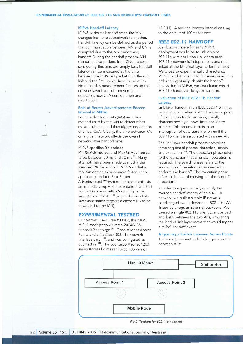
EXPERIMENTAL TESTBED Our testbed used FreeBSD 4.x, the KAME M[Pv6 stack (snap kit kame-20040628-freebsd49-snap.tgz 161), Cisco Aironet Access Points and a NetGear 802.11 b network interface card 1121, and was configured as outlined in 1131. The two Cisco Aironet 1200
series Access Points ran Cisco [OS version
Hub 10 Mbitls
Mobile Node
12.2(11) JA and the beacon interval was set to the default of 1 OOms for both.
IEEE 802.11 HANDOFF An obvious choice for early M[Pv6 deployment would be to link disjoint 802 .11 b wireless LANs (i.e. where each 802.11 b network is independent, and not
linked at the Ethernet layer to form an ESS) . We chose to experimentally characterise M[Pv6 handoff in an 802.11 b environment. [n
order to eventually identify the handoff delays due to M[Pv6, we first characterised 802.11 b handover delays in isolation.
Evaluation of IEEE 802.11 b Handoff Latency Link-layer handoff in an [EEE 802 .11 wireless
network occurs when a MN changes its point of connection to the network, usually characterised by a move from one AP to another. This process results in an
interruption of data transmission until the 802.11 b client is associated with a new AP.
The link layer handoff process comprises three sequentia l phases: detection, search and execution 114
). The detection phase refers
to the realisation that a handoff operation is required. The search phase refers to the acqu isition of the information needed to perform the handoff. The execution phase
refers to the act of carrying out the handoff procedure.
[n order to experimenta lly quantify the average handoff latency of an 802.11 b network, we built a simple [P network consisting of two independent 802.11 b LANs
linked by a regular Ethernet backbone. We caused a single 802.11 b client to move back and forth between the two APs, simulating the kind of link layer move that would trigger a M[Pv6 handoff event.
Triggering a Switch between Access Points There are three methods to trigger a switch
between APs:
Sniffer Box
. \ -
Fig 2. Testbed for 802. 11 b handoffs
EXPERIMENTAL EVALUATION OF IEEE 802.11B AND MOBILE IPV6 HANDOFF TIMES
1. Decrease the transmission power of the AP that the MN is currently associated with. The MN will detect the degraded signal strength and switch to another AP, as long as they both have the same SSID.
We evaluated methods 1 and 2.
A simple bridged Ethernet network was established, with one fixed host
communicating to a wireless host that had one of two APs to choose from at any given time. Both APs were connected directly to a common Ethernet hub (Figure 2).
2. Ensure the APs have different SSIDs, and change the BSS configured into the client
when an AP switch is required. A generic FreeBSD 4.9 host was used to sniff traffic on the wired LAN side (the 'sniffer
box'). In order to 'see' the affect of switching AP, we generated IPv4 ping (ICMP) packets
3. Administratively shut down the 802 .11
radio interface, or physically turn off the AP the MN is currently associated with.
-I/) --
800 handoffs of 802.11 b handoffs
4.0 r------------------------,
3.5 ....
3.0
1 81 161 241 321 401 481 561 641 721
hand off number
Fig. 3. Handoff times, alternating 5510s, APs on same channel
?fi.
Cumulative distribution of 802.11 b handoff samples
100
80
60
40
20
o
• "... •
..J •
L() 0 L() 0 L() 0 L() 0 L() 0 L() 0 L() 0 L() 0 OML()COOML()COOML()COOML()CO L() L() L() L() <.0 <.0 <.0 <.0 ,.... ,.... ,.... ,.... co co co co
handoff latency (ms)
Fig. 4 - Cumulative distribution of 802. 11 b handoff samples; Handoff times, alternating 55/0s, APs on same channel
EXPERIMENTAL EVALUATION OF IEEE 802.11 B AND MOBILE IPV6 HANDOFF TIMES
.-
at 10ms intervals across the 802. 11 b wire less link.
Method 1: Triggering Handoff by Varying Access Point Transmission Power Levels For the first approach to triggering handoffs we configured both APs to be in the same
BSS, 'magicap'.
Given the 10ms sampling interva l, and the
rough ly 3ms RTI of our testbed, our estimates are ± 13ms. Excluding the data
points greater than 2s, we arrive at a mean 802.11 b handoff time of 864ms, ranging from 682ms to 946ms.
Method 2: Triggering Handoff by Alternating Mobile Node's SSID Association Our alternative approach invo lved both APs being configured to transmit with the same signal power, but with different SSIDs -. 'magicap1' and 'magicap2' for AP1 and AP2
respective ly.
Figure 3 shows the scatter plot of 800 handoff trials. Excluding the small number (1 .34%) of samples over 2s, the mean switch ing time is 631 ms (a min imum of 506ms and maximum 781 ms). Figure 4 shows the distribution of handoff times
between 506ms and 781 ms more clearly.
We also re-ran th ese tria ls with the APs on different channels (AP1 on channe l 4 and
AP2 on channe l 10). Tab le 1 summarises the results after exclud ing the few data points over 2 seconds.
Analysing our Experimental 802.11 b Handoff Results Method 1 deals with all three handoff phases - detection, search and execution. The
802. 11 b client must detect its movement, search for available channels to associate with and execute the handoff. Method 2 eliminates the detection phase, resulting in a lower mean handoff va lue (63 1 ms compared to 864ms).
In the search phase, the MN has to scan all the different radio channels to be reassociated with an AP. The scann ing can be done by li sten ing for beacon messages from
APs or by send ing a probe request message on each channel and wait ing on that chan nel for probe responses from APs. If the MN does not receive responses from A Ps it has
to wait until a wait ing t imeout on each
channel.
The resu lts of A.Mishra et al [161 find the
802.11 b link layer handoff to be in the range 58 ms to 397 ms. They also found that the search phase was the most sign ificant contributor to the handoff latency. The type of wire less card f irmware can have a large impact as well - we observe that the
NetGear wire less NIC scans for channels in random order, wh ilst other wireless NICs firmware can search through channels in ascending or descending order.
Our measured handoff is genera lly longer than reported in other literatu re because we are measuring the entire t ime it takes for
actua l Ethernet level bridging to successfully resume after re-association with a new (or previous) A P. We also observed that if the two A Ps are in the same channe l, the search time reduces a further 35 to 45 ms.
Our primary goa l was to account for the contribution of 802.1 1 b handoff to our later MIPv6 handoff measurements, so we did not explore 802 .11 b-specific methods of improving link layer handoff times beyond
the default sett ings of our commercia l
equipment.
MEASURED MOBILE IPV6 HANDOFF OVER IEEE 802.11 B We now experimenta lly determ ined the handoff t ime when using MIPv6 over the
802. 11 b network.
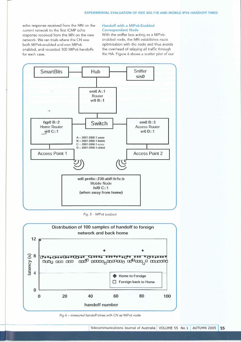
The MIPv6 Testbed and Experimental Approach Our MIPv6 testbed is shown in Figure 5. All wired NICs were explicitly configured to run at 10Mb it/s. AP 1 (Access Point 1) was configured w ith SSI D 'magicap1' on channe l
10. AP2 was configured with SSID 'magicap2' on channel 4. We chose to trigger 802.1 1 b network switch ing by
chang ing th e SSID every 20s.
The first two trials saw the sniffer box used as
a CN, by having it send IPv6 ping traffic at 10ms interva ls to the MN and monitoring all inbound and outbound traffic with tcpdump[151.
The handoff time was calcu lated by measuring the time between the last ICMP
r Both APs on Ch . 10 APs on Ch . 4 and Ch . 10 respectively """
Mean 802.11 b handoff 631ms 667ms
Longest handoff 781ms 82Sms
Shortest handoff S06ms S06ms
" ./
Table 1. Summary of alternating SSID handoff times
EXPERIMENTAL EVALUATION OF IEEE 802.11B AND MOBILE IPV6 HANDOFF TIMES
Handoff with a MIPv6-Enabled Correspondent Node
echo response received from the M N on the
current network to the first ICMP echo
response recei ved from the MN on the new
network. We ran tri als where the CN was
both MIPv6-enabled and non MIPv6-
enabled, and recorded 100 MIPv6 handoffs
for each case .
With the sniffer box acting as a MIPv6-
enabled node, the MN establishes route
optimisation with the node and thus avoids
the overhead of relaying all traffic through
the HA. Figure 6 shows a scatter plot of our
/
,
I
I
12
~8 >. u s:::: CI) .... C'CJ 4
o
SmartBits I I Hub I Sniffer I I I sisO
I . emO A::1
Router vrO B::1
-.... I
f~pO B::2 I Switch I emO B::3 Home Router I I Access Router
vrO C::1 vrO D::1 ,-A ~ 2001 :DB8:1 :aaaa B ~ 2001:DB8:1:bbbb
I C ~ 2001 :DB8:1 :cccc
I o ~ 2001:DB8:1:dddd
Access Point 1 b I Access Point 2
o
~ wiO prefix ::230:abff:fe1c:b
Mobile Node hifO C::1
(when away from home)
Fig. 5 - MfPv6 testbed
Distribution of 100 samples of handoff to foreign
network and back home
• Home to Foreign
o Foreign back to Home
20 40 60 80
handoff number
Fig 6 - measured handoff times with eN as MfPv6 node
"
I
~
100
--EXPERIMENTAL EVALUATION OF IEEE 802.11B AND MOBILE IPV6 HANDOFF TIMES
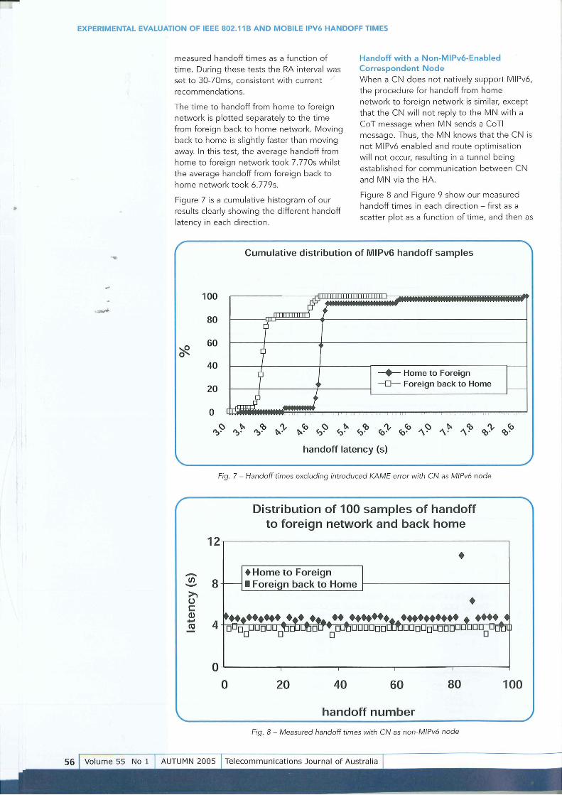
measured handoff t imes as a function of
time. During these tests the RA interval was set to 30-70ms, consistent w ith current J
recommendations .
The time to handoff from home to foreign
network is plotted separate ly to the time
from foreign back to home network. Moving
back to home is slightly faster than moving
away. In this test, the average handoff from
home to foreign network took 7.770s whi lst
the average handoff from fore ign back to
home network took 6.779s.
Figure 7 is a cumulative histogram of our
results clearly showing the different handoff
latency in each directio n.
/
Handoff with a Non-M IPv6-Enabled Correspondent Node When a CN does not natively support MIPv6,
the procedure for handoff from home
network to foreign network is similar, except
that the CN w ill not reply to the MN w ith a
CoT message when M N sends a Co TI
message . Thu s, the MN knows t hat the CN is
not MIPv6 enabled and route optimisation
will not occur, resulting in a tunnel being
estab li shed for commun ication between CN
and MN via the HA.
Figu re 8 and Figure 9 show our measured
handoff times in each direction - first as a
scatter plot as a function of time, and then as
'" Cumulative distribution of MIPv6 handoff samples
?fl.
'-
-If) "-"
100
~f 80 9' 60
7 40 0 --+- Home to Foreign
20 ~ -0- Foreign back to Home I---
f ~ 0 1.11 , "
, , I II I II, II I II III , I I II , II , , I' <i
Fig. 9 - Handoff times excluding introduced KAME error with eN as non-MIPv6 node
6.0
5.0
4.0
3.0
030
Hand·off times versus RA intervals
... 'I' 5.322
..to.
~~017 4.75
'I' 5.106
3.638
70 100
L-_-----O-~ 3.894
-lJ""3.707
200
RA intervals (ms)
4.036
~ Home to Foreign
~ Foreign back to Home
500
Fig. 10 - Handoff times vs RA intervals
800
EXPERIMENTAL EVALUATION OF IEEE 802.11 B AND MOBILE IPV6 HANDOFF TIMES
•
.-
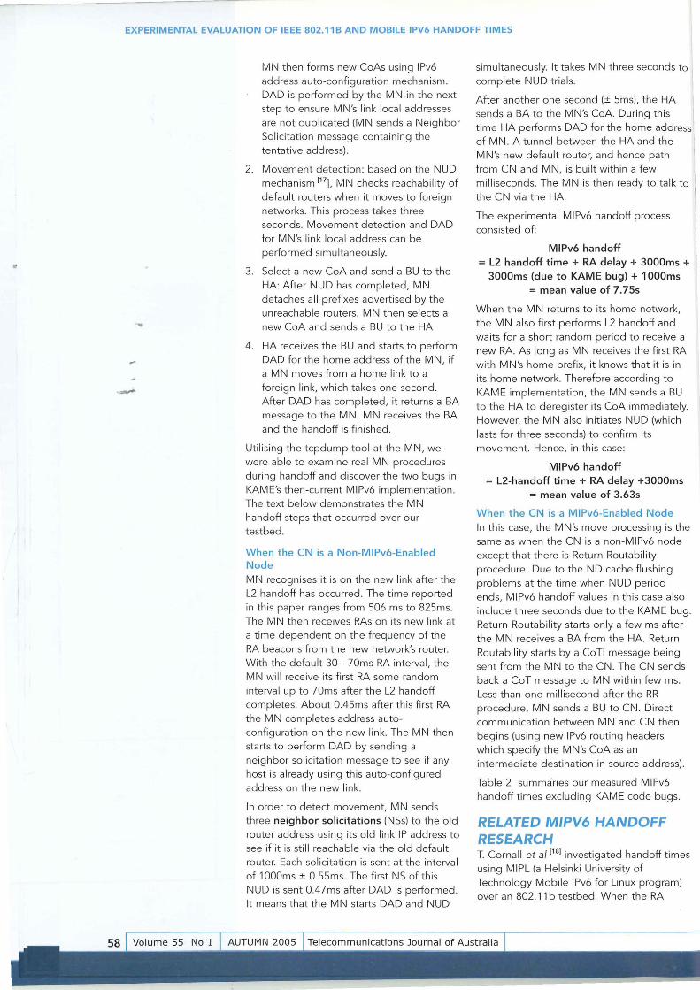
MN then forms new CoAs using IPv6 address auto-configuration mechan ism. DAD is performed by the MN in the next step to ensure MN's link loca l addresses
are not duplicated (MN sends a Neighbor Solicitation message conta in ing the tentative address).
2. Movement detection: based on the NUD mechanism [17], MN checks reachab ility of
default routers when it moves to foreign networks. Th is process takes three seconds. Movement detection and DAD for MN's link local address can be
performed simultaneously.
3. Select a new CoA and send a BU to the
HA: After NUD has completed, MN detaches all prefixes advertised by the unreachable routers. MN then se lects a new CoA and sends a BU to the HA
4. HA receives the BU and starts to perform DAD for the home address of the MN, if a MN moves from a home link to a
fore ign link, which takes one second. After DAD has completed, it returns a BA message to the MN. MN receives the BA and the handoff is finished .
Utili sing the tcpdump tool at the MN, we were ab le to examine real MN procedures during handoff and d iscover the two bugs in
KAM E's then-current MIPv6 implementation. The text below demonstrates the MN handoff steps that occurred over our testbed.
When the CN is a Non-MIPv6-Enabled Node
MN recognises it is on the new link after the L2 handoff has occurred. The time reported in this paper ranges from 506 ms to 825ms. The MN then receives RAs on its new link at
a time dependent on the frequency of the RA beacons from the new network's router. With the default 30 - 70ms RA interva l, the MN wi ll receive its f irst RA some random interval up to 70ms after the L2 handoff
completes. About 0.45ms after this first RA the MN completes address autoconfigurat ion on the new link. The MN then starts to perform DAD by sending a neighbor so licitation message to see if any host is already using this auto-configured address on the new link.
In order to detect movement, MN sends three neighbor solicitations (NSs) to the o ld router address using its old link IP address to see if it is still reachable via the old defau lt router. Each so licitation is sent at the interva l of 1000ms ± 0.55ms. The first NS of this NUD is sent 0.47ms after DAD is performed .
It means that the MN starts DAD and NUD
simu ltaneously. It takes MN three seconds to complete NUD tria ls.
After another one second (± 5ms), the HA sends a BA to the MN's CoA. During thi s
time HA performs DAD for the home address of MN . A tunnel between the HA and the
MN's new default router, and hence path from CN and MN, is bui lt within a few milliseconds. The MN is then ready to ta lk to the CN via the HA.
The experimental MIPv6 handoff process
consisted of:
MIPv6 handoff
= L2 handoff time + RA delay + 3000ms + 3000ms (due to KAME bug) + 1000ms
= mean value of 7.75s
When the MN returns to its home network, the MN also first performs L2 handoff and wa its for a short random period to receive a new RA. As long as MN receives the fi rst RA wi th MN's home prefix, it knows that it is in
its home network. Therefore accord ing to KAME implementation, the MN sends a BU to the HA to deregister its CoA immediately. However, the MN also initiates NUD (which lasts for three seconds) to confirm its
movement. Hence, in this case:
MIPv6 handoff = L2-handoff time + RA delay +3000ms
= mean value of 3.63s
When the CN is a MIPv6-Enabled Node
In this case, the MN's move processing is the same as when the CN is a non-MIPv6 node except that t here is Return Routab ility procedure. Due to the ND cache flushing
problems at the time when NUD period ends, MIPv6 handoff va lues in this case also include three seconds due to the KAME bug. Return Routability starts on ly a few ms after the MN receives a BA from the HA. Return
Routabi lity starts by a CoTI message being sent f rom the MN to the CN. The CN sends back a CoT message to MN within few ms. Less than one millisecond after the RR
procedure, MN sends a BU to CN. Direct communication between MN and CN then begins (using new IPv6 routing headers which specify the MN's CoA as an intermediate destination in source address).
Table 2 summaries our measured MIPv6 handoff times exclud ing KAME code bugs.
RELATED MIPV6 HANDOFF RESEARCH T. Cornall et al [18] investigated handoff times
using MIPL (a Helsinki University of Technology Mobile IPv6 for Linux program) over an 802 .11 b testbed. When the RA
EX PERIMENTAL EVALUATION OF IEEE 802.11B AND MOBILE IPV6 HANDOFF TIMES
/' MIPv6 handoff including Average handoff from Average handoff from ""\ link layer handoff home to foreign network foreign back to home
(in s) network (in s)
CN is MIPv6 node (RA interval: 30ms 70ms) 4.770 3.779
CN is non MIPv6 node 3.638 (RA interval: 30ms -70ms) 4.75
~ '-Table 2. Summary of MIPv6 handoff trials
interval is between 0.5 seconds and 1.5 seconds, their measured handoff times are 1.1 seconds returning to the home network and 1.8 seconds moving to foreign network. Related work by R. Hsieh et al [19], based on a simulation setup for an 802 .11 network,
gives their mean measured basic MIPv6 handoff to foreign network around 5487ms.
D. Le et al (20) als1'5 used MIPL, and observed
no packet losses in MIPv6 handoff in M IPv6 WLAN networks while the CN was pinging their MN. Inste;d they saw only the RTI
increase from 3~95ms to 89.23ms. We suspect their1Vi'N movement only incurred L2 handoff since the default router was still reachab le when MN attached to the new link. It wou ld appear their trials did not
trigger actual MIPv6 handoff.
N. Montavont et al )21) reported MIPv6
latency va lues over an 802.1 1 b network rang ing from around 300ms to 1.7s when the RA interval is 50ms. When RA interval is 1500ms MIPv6 handoff latencies are between 1.8s and 3s. Unfortunately, there is little
detail provided regarding the tools they used to measure handoff latency.
Our results reflect an up-to-date KAM E implementation consistent with the current MIPv6 RFC 3775 141. The NUD process
accounts for most of the MIPv6 handoff
duration in KAME as it always takes 3 seconds.
RFC 3775 states that due to the temporary packet flow disruption and signaling overhead involved in updating mobility bindings, the Mobile Node should avoid
performing a L3 handover until it is strictly necessary .. Therefore, the NUD process helps to determine unreachable default or current router(s) known to the MN and then helps to confirm L3 movement after MN has discovered routers and prefixes on the new
link.
Specific optimisations are possible, both within each layer (link or network) and
between each layer (using link layer state changes to expedite network layer awareness of the need for MIPv6 handoff).
Cumulative distribution of webcam performance over 30
handoff samples
100.0
80.0
60.0
'eft. 40.0 -
--0- handoff time
20.0 --+-- webcam interrupted
.0
4 5 6 7 8 9 10 11 12
handoff latency (s)
Fig. 11 - Webcam performance over handoffs from home to foreign network
Telecommunications Journal of Australia VOLUME 55 No 1
-I
EXPERIMENTAL EVALUATION OF IEEE 802.11B AND MOBILE IPV6 HANDOFF TIMES
.-
However, the focus of our work in this paper
has been to measure the intrinsic limitations
of a MIPv6 implementation where there are
no such optimisations - indeed, our results
provide further justification for tighter
coupling between link layer and network
layer protocols in order to significantly
improve the resulting handoff t imes.
APPLICATION PERFORMANCE OVER M/PV6 HANDOFF Webcam Performance Over MIPv6 with Simulated Handoff Events An interesting question is how MIPv6 handoff
wou ld affect a common webcam application
where one of the parties was a Mobile Node
in motion. To test this scena rio we ran a two
party webcam conference between two
Windows 2000 hosts through a FreeBSD
4.10 - based bridge using a popular
application, Yahoo!Messenger version
6.0.0.1643. The bridge repeatedly blocked
and unblocked IP commun ication between
its two network interfaces, timing the
blocked state to mimic our measured MIPv6
handoff latencies.
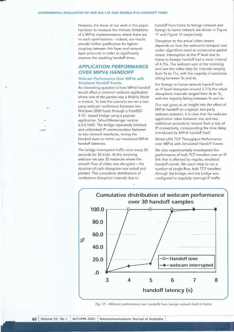
The bridge interrupted traffic once every 20
seconds for 30 trials. At the receiving
webcam we saw 30 instances where the
smooth flow of video was disrupted - the
duration of each disruption was noted and
plotted. The cumu lative d istributions of
conference disruption intervals due to
handoff from home to fore ign network and
foreign to home network are shown in Figure
11 and Figure 12 respectively.
Disruption to the actua l video stream
depends on how the webcam's transport and
codec algorithms react to consecut ive packet
losses. Interruption at the IP leve l due to
home to foreign handoff had a mean interval
of 4.75s. The webcam user at the receiving
end saw t he video stop for intervals ranging
from 5s to 11 s, with the majority of estimates
sitt ing between 5s and 6s.
For foreign to home network handoff (with
an IP leve l d isruption around 3.77s) the visual
disruptions intervals ranged from 4s to 7s,
with the majority falling between 5s and 6s.
Our test gives us an insight into the effect of
MIPv6 handoff on a typical, two-party
webcam scenario. It is clear that the webcam
application takes between one and two add itiona l seconds to recover from a loss of
IP connectivity, compounding the time delay
introduced by MIPv6 handoff itself.
Wired LAN TCP Throughput Performance
over MIPv6 with Simulated Handoff Events
We also experimenta lly investigated the
performance of bu lk TCP transfers over an I P
link that is affected by regu lar, emu lated
handoff events. We used nttcp to run a
number of sing le-fl ow, bulk TCP transfers
through the bridge, and the bridge was
configu red to regularly interrupt IP traffic
Cumulative distribution of webcam performance over 30 handoff samples
100.0 '
80.0
60.0 ?ft.
40.0
20.0 1- - ----- - 1----1 -0- Handoff time
-+- webcam interrupted
.0
3 4 5 6 7 8
handoff latency (s)
Fig. 12 - Webcam performance over handoffs from foreign network back to home
"'*I
EXPERIMENTAL EVALUATION OF IEEE 802.11B AND MOBILE IPV6 HANDOFF TIMES
flow in the same manner as wou ld be experienced if the IP path ran through a MIPv6 li nk during handoffs.
Figure 13 shows the nttcp bandwidth versus handoff rate.
The data label on each plot specifies our measured throughput and the time taken to complete data transfer for each handoff rate tria l. Handoff disruptions have a relatively significant impact on TCP throughput, and
we can see that as the handoff rate increases, the throughput achieved by nttcp decreases. The decrease in throughput appears to be linear up to 7 handoffs/min, after which the relationship becomes non
linear.
CONCLUSION By implementing an 802. 11 b wireless
network and overlaying a mobile IPv6 network on top"of it, we were ab le to
experimentally f ri gger handoff events and measure the trm"e period during which
connectivity was lost.
We found that rea l-worl d 802.1 1 b handoffs
were typica lly completed in less than 700ms. The IP leve l disruption due to 802.1 1 band MIPv6 handoff together was sign ificantly higher - around 4.8 and 3.8 seconds depending on the d irection of handoff (home
to foreign network or foreign to home network respectively). Tun ing the router advertisement (RA) interva ls from 30 - 70ms (the defau lt) to 500 - 800ms did not significantly degrade these handoff times.
This suggests that short RA interva ls may, in
practice, not be worth the transm ission overhead , particularly for resourceconstra ined environments (e.g. limited
bandwidth or battery power).
These results clearly show that a default MIPv6 environment would be high ly d isruptive to real-time and interactive applications during handoff events, even if the underlying link-layer handoff was instantaneous. We have also seen how simple implementation bugs can cause substantia l increases in the handoff latencies, regard less of the actua l MIPv6 protocol itself.
Further research will be required to
investigate how each component of the layer 3 (M IPv6) handoff detection, configuration
and reg istration times contribute to the overall handoff time, and what factors can be used to reduce each component. Further
work is also required to investigate packet loss and jitter during mobile IP handoff operations. Benchma rking some of the ava ilab le methods for Mobile Node fast movement detection - e.g. predictive and
non-predictive handoff optim isations using RAs, fast handovers for MIP over WLANs
using layer 2 tri ggers etc. - wou ld also provide useful information for those interested in mobile IPv6 and its
applications.
REFERENCES [1] J. Postel, Internet Protoco l DARPA
Internet Program Protoco l Specificat ion , RFC 791, in ternet Engineering Task Force, September 1981
EXPERIMENTAL EVALUATION OF IEEE 802.11B AND MOBILE IPV6 HANDOFF TIMES
[2] S. Bradner and A. Mankin, The [15] Tcpdump, http://www.tcpdump.org/ Recommendation for the IP Next (as of January 2005) Generation Protocol, RFC 2460, [16] A. Mishra, M . Shin, and W.Arbaugh, An Internet Engineering Task Force, Empirical Analysis of the IEEE 802.11 January 1995 MAC Layer handoff Process, Technical
[3] S. Deering and R. Hinden, Internet Report CS-TR-4395 UMIACS- TR-2002-Protocol, Version 6 (IPv6) Specification, 75, 2002, University of Maryland RFC 2460, Internet Engineering Task [17] T. Narten, E. Nordmark, and W. Force, December 1998 Simpson, Neighbor Discovery for IPv6,
[4] D. Johnson, C. Perkins, and J. Arkko, RFC 2461, Internet Engineering Task Mobility Support in IPv6, RFC 3775, Force, December 1998 Internet Engineering Task Force, June [18] T. Corna ll , B. Pentland, and K. Pang, 2004 Improved Handover Performance in
[5] C. Perkins, IP Mobi lity Support, RFC wireless mobi le IPv6, The 8th 3344, Internet Engineering Task Force, International Conference on August 2002 Communication Systems, ICCS 2002,
[6] The KAME Project, http://kame.netl Singapore, Volume: 2, 25-28 November
(as of January 2005) 2002
[7] The FreeBSD Project, [19] R. Hsieh et ai, Performance Analysis on Hierarch ical Mobile IPv6 with Fast-http://www.freebsd.org/ (as of handoff over End-to-End TCP, Global January 2005) Telecommunications Conference,
[8] P. Brenner, A Technical Tutorial on the GLOBECOM '02. IEEE, Volume: 3, IEEE 802.11 Protocol, BreezeCom Pages: 2488 - 2492, Taipei, Taiwan, Wireless Communications, 1997 17-21 November 2002
[9] C. Perkins, Mobile Networking through [20] D. Le, D. Guo, and B. Wu, Mobile IPv6 Mobi le IP, IEEE Computer Society in WLAN Mobile Networks and its Tutorial. Implementation, 14th IEEE Proceedings http://www.computer.org/internet/v2 on Personal, Indoor and Mobile Radio n1 /perkins .htm (as of January 2005) Communications, Proceedings PIMRC
[10] J. Kempf, M. Khalil, and B. Pentland, 2003, Beijing, China, Volume: 2, 7-10
IPv6 Fast Router Advertisement, IETF September 2003
Internet Draft, Ju ly 2004, draft-mkhalil- [21 ] N . Montavont and T. Noel, Analysis and ipv6-fastra-05. txt Evaluation of Mobile IPv6 Handovers
[11] J. Choi and D. Sh in, Fast Router over Wire less LAN, Mobile Networking
discovery with RA caching in AP, IETF and Applications (MONET), special
Internet Draft, Ju ly 2004, draft-jinchoi- issue on Mobile Networking through
dna-frd-OO.txt IPv6 or IPv4, Volume 8, Number 6,
Netgear 802 .11 b Wire less PC Card, Kluwer Academic Publishers November [12] 2003 http://www.netgear.com/products/de
tails/MA401.php (as of January 2005) THE AUTHORS [13] L. Stewart, M. Banh, and G. Armitage, Mai Banh is currently completing a Masters
Implementing an IPv6 and Mobile IPv6 degree by Research in Telecommunications testbed using FreeBSD 4.9 and KAME, at the Centre for Advanced Internet CA IA Technical Report 040331A, March Architectures, Swinburne University of 2004. Technology, Melbourne, Australia . She
[14] IEEE Std 802.11, 1999 Edition (ISO/ IEC received the degrees of Bachelor of Engineering and Diploma in Practice in
8802-11: 1999) IEEE Standard for Telecommunications from the University of
Information Technology- Technology, Sydney, in December 2002. Telecommunications and Information
Mai's research interests include IP Mobility, Exchange between Systems - Loca l
802.11 b and Mobile IPv6 handoff, wireless and Metropolitan Area Network- technologies, and QoS in wireless and Specific Requirements - Part 11: broadband networks. Wireless LAN Medium Access Contro l She may be contacted by email : (MAC) and Physica l Layer (PHY) [email protected], or by phone: Specifications +61 3 92144844.
n
5
EXPERIMENTAL EVALUATION OF IEEE 802.11B AND MOBILE IPV6 HANDOFF TIMES
Lawrence Stewart is a Research Assistant at the Centre for Advanced Internet Architectures, Swinburne University of Technology, Melbourne, Australia.
His research interests include IPv6, mobility, networked multi player games and the FreeBSD operating system. He is also currently completing an undergraduate double degree Bachelor of Engineering (Telecommunications and Internet Technologies) / Bachelor of Science (Computer Science and Software Engineering) at Swinburne University of Technology.
He may be contact€d by emai l: [email protected], or by phone: +61 3 92144530.
Grenville Armitage is Associate Professor of Telecommunications Engineering and Director of the Centre for Advanced Internet Archite-ctures at Swinburne University of Technology, Melbourne, Australia.
He received his PhD and Bachelor degrees in Electronic Engineering from the University of Melbourne, Australia.
Between 1994 and 2001 he held research staff positions in Bellcore (now Telcordia Technologies, New Jersey, USA). Be ll Labs Research (New Jersey, USA), and Be ll Labs Research Silicon Va ll ey (California , USA). He has a lso held positions as Product Marketing Director and Manager within Lucent Technologies (New Jersey, USA).
His current research interests include networked games, IP traffic pattern ana lysis, broadband IP access architectures, network security, development of efficient teaching tools for undergraduate networking courses and generally re-eng ineering the Internet so that we forget it is even there. He is the author of Q uality of Service In IP Networks: Foundations for a Multi-Service Internet, and co-chaired the First Australian Workshop on Network Support for Interactive Multimedia and Games (NSIM 2004).
Professor Armitage is a member of IEEE and ACM SIGCOMM, and can be contacted by email: [email protected], or by phone: +61 3 92148373.