Revista Ciência Agronômica ISSN: 0045-6888 [email protected]Universidade Federal do Ceará Brasil Cardoso, Kelen Cristiane; Gazzola, Jonathan; Dal Fabbro, Inacio Maria Application of Moiré technique on strain analysis in farm machinery elements Revista Ciência Agronômica, vol. 45, núm. 3, julio-septiembre, 2014, pp. 479-487 Universidade Federal do Ceará Ceará, Brasil Available in: http://www.redalyc.org/articulo.oa?id=195330648007 How to cite Complete issue More information about this article Journal's homepage in redalyc.org Scientific Information System Network of Scientific Journals from Latin America, the Caribbean, Spain and Portugal Non-profit academic project, developed under the open access initiative
Revista Ciência Agronômica, v. 45, n. 3, p. 479-487, jul-set, 2014Centro de Ciências Agrárias - Universidade Federal do Ceará, Fortaleza, CEwww.ccarevista.ufc.br ISSN 1806-6690
Artigo Científico
Application of Moiré technique on strain analysis in farm machineryelements1
Aplicação da técnica de Moiré na análise de deformação em elementos de máquinasagrícolas
Kelen Cristiane Cardoso2*, Jonathan Gazzola2 e Inacio Maria Dal Fabbro2
ABSTRACT - Development and optimization of projects for agricultural machinery involve the analysis of stress andstrain. Moiré photomechanical techniques provide a complete displacement field of the specimen under test, and canaid in understanding the mechanical behavior of parts with complex geometry. Hybrid methods combine fringe patternsof displacement with distribution maps of stress and strain through concepts of the theory of elasticity. The objectiveof this work was to analyse the use of the shadow moiré technique in the qualitative determination of stress and straindistribution in geometrically complex machine elements. The results were compared with those from an electricalextensometer and a computer simulation. The results demonstrated that the shadow moire technique was quite reliablein analysing the mechanical behavior of geometrically complex machine elements.
RESUMO - Desenvolvimento e otimização de projetos de máquinas agrícolas envolvem a análise de tensão edeformação. Técnicas fotomecânicas de moiré fornecem campo de deslocamento completo do corpo de prova e podemauxiliar no entendimento do comportamento mecânico de peças com geometria complexa. Métodos híbridos associamfranjas padrões de deslocamento com mapas de distribuição de tensão e deformação, através de conceitos de teoria daelasticidade. O objetivo deste trabalho foi analisar o uso da técnica de moiré de sombra para determinação qualitativa dedistribuição de tensão e deformação em elementos de máquinas de geometria complexa. Os resultados foram comparadoscom o método de extensometria elétrica e por simulação computacional. Os resultados mostraram que a técnica de moiré desombra foi bastante confiável para analisar o comportamento mecânico de elementos de máquinas de geometria complexa.
Palavra-chave: Máquinas Agrícolas. Técnicas Fotomecânicas. Moiré de sombra.
*Autor para correspondência1Recebido para publicação em 19/04/2013; aprovado em 23/03/2014 Parte da Dissertação de Mestrado do primeiro autor apresentada ao curso de Pós-Graduação em Máquinas Agrícolas/Engenharia Agrícola daUniversidade Estadual de Campinas
Rev. Ciênc. Agron., v. 45, n. 3, p. 479-487, jul-set, 2014480
K. C. Cardoso et al.
INTRODUCTION
In agricultural science, mainly in farm machinerydesign and development, the association of stress andstrain analysis to product optimization is of very commonoccurrence. Accurate analyses are based on isolated elementtests through experimental techniques (MAZZETI FILHOet al., 2004). Strain-gage techniques generate point topoint deformation and displacement data, requiring manysensors conveniently positioned which demands time andcost increase (RI; FUJIGAKI; MORIMOTO, 2010).
Mechanical components shapes are verycommonly surveyed by means of optical techniques whichcan be associated to interferometry to generate solutionsto problems involving static or dynamic situations(GOMES et al., 2009). Optical methods are usually namedphotomechanical techniques which are able to generatecomplete displacement field (ANDONIAN, 2008) beingrecognized as stress analysis experimental methods (LEIet al., 2007). Stress field can also be determined by meansof hybrid methods which associate optical techniques withthe theory of elasticity (DOYLE, 2008).
Moiré techniques are include in the photomechanicalcategory which are based on optical interferometry, whichyield excellent results in determining displacement field,however it requires adequate fringes spatial differentiationto generate stress and deformation fields. The advantagesof moiré methods are associated to low cost of requiredequipment, low sensitivity to external noise, fast trials aswell as and applicability to large displacement determination(DOYLE, 2008; GLEICE et al., 2011; RYU et al., 2008).
The moiré phenomenon takes place when twooptical grids of certain density are superposed at a specificangle; fringes are generated with different period and angleof the two initial screens (LINO; DAL FABBRO, 2004).The third group of strips is denominated as moiré fringeswhich vary from dark color when generated by destructiveinterfering waves to totally clear color if generated byconstructive interfering waves (BERALDO et al., 2007).
Moiré fringes can be generated by means of theshadow moiré or by the projection moiré method (PORTO;GURGEL; FARINATTI, 2011). In shadow moiré method,the grid is positioned in front of the testing body andilluminated by a light source, projecting the grid shadeonto the object surface. Costa et al. (2008) recommend theapplication of that technique in deformation test, becausethat method generates more detailed fringes.
The application of moiré methods tophotomechanical tests are based on the superposition oftwo sets of fringes generated on the loaded as well as on theunloaded testing body, respectively (XIAO et al., 2010).Image processing will generate the displacement field
followed by the deformation and stress field (BASTOS;TAVARES, 2004).
The pertinent literature discloses several researchreports on the application of moiré methods to determinethe qualitative stress state on bodies of simple geometry.Mazzeti Filho et al. (2004) report the application of a moirémethod to determine the displacement field on rubberdiscs models. Albiero et al. (2012) determined points ofisodeformation on nuts shell surface. Gazzola et al. (2012)report qualitative determinations of stress distribution ofwood beams under flexural loading.
The objective of this research work was to analyzethe application of shadow moiré method to a qualitativedetermination of deformation and stress distribution onfarm machinery elements of complex geometry.
MATERIALS AND METHODS
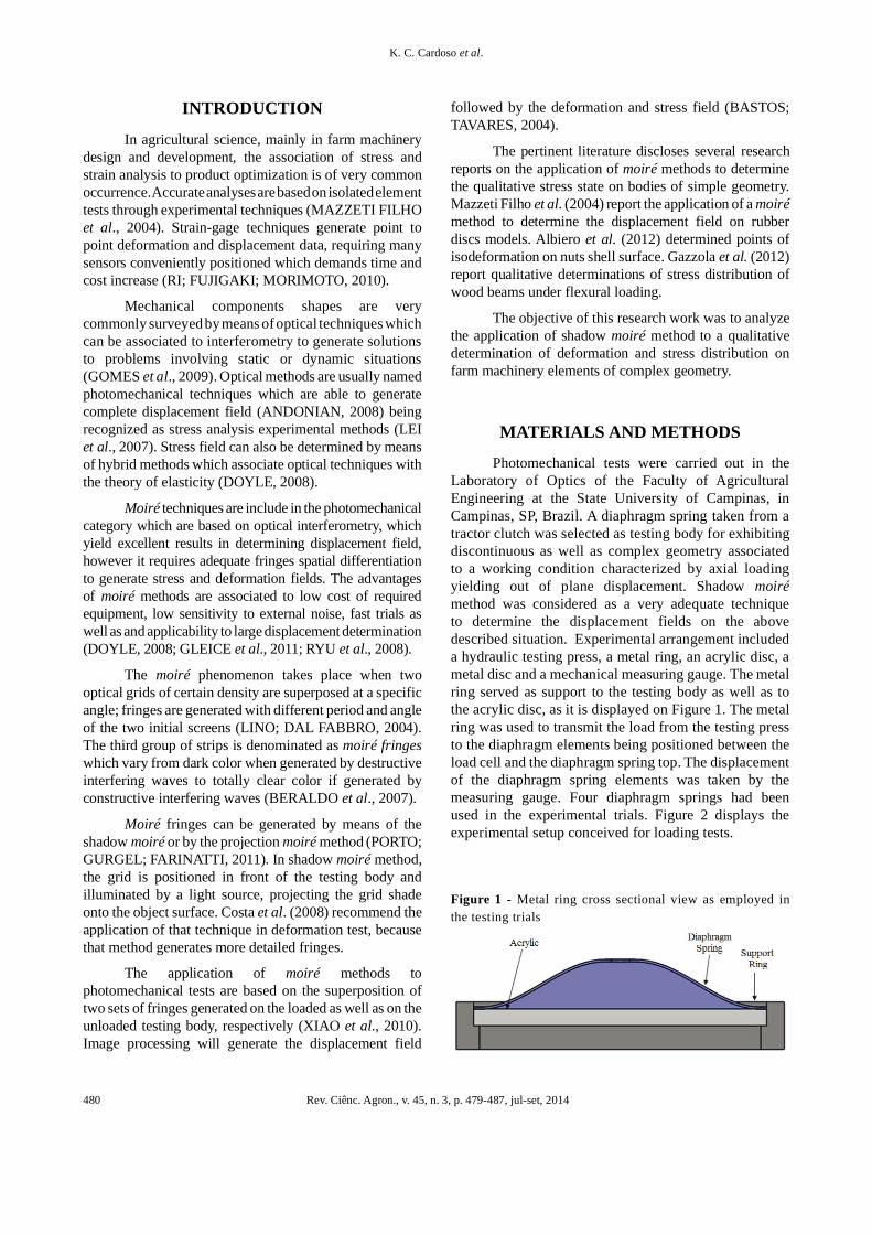
Photomechanical tests were carried out in theLaboratory of Optics of the Faculty of AgriculturalEngineering at the State University of Campinas, inCampinas, SP, Brazil. A diaphragm spring taken from atractor clutch was selected as testing body for exhibitingdiscontinuous as well as complex geometry associatedto a working condition characterized by axial loadingyielding out of plane displacement. Shadow moirémethod was considered as a very adequate techniqueto determine the displacement fields on the abovedescribed situation. Experimental arrangement includeda hydraulic testing press, a metal ring, an acrylic disc, ametal disc and a mechanical measuring gauge. The metalring served as support to the testing body as well as tothe acrylic disc, as it is displayed on Figure 1. The metalring was used to transmit the load from the testing pressto the diaphragm elements being positioned between theload cell and the diaphragm spring top. The displacementof the diaphragm spring elements was taken by themeasuring gauge. Four diaphragm springs had beenused in the experimental trials. Figure 2 displays theexperimental setup conceived for loading tests.
Figure 1 - Metal ring cross sectional view as employed inthe testing trials
Rev. Ciênc. Agron., v. 45, n. 3, p. 479-487, jul-set, 2014 481
Application of Moiré technique on strain analysis in farm machinery elements
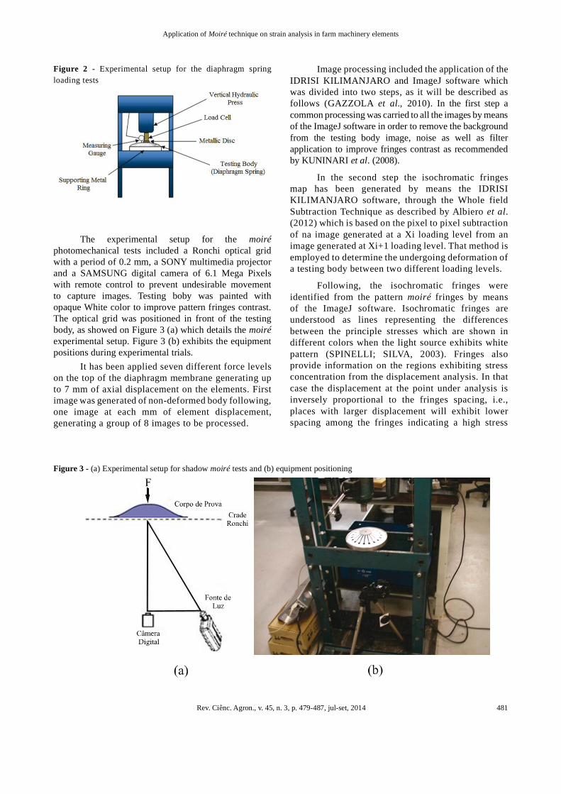
Figure 2 - Experimental setup for the diaphragm springloading tests
Figure 3 - (a) Experimental setup for shadow moiré tests and (b) equipment positioning
The experimental setup for the moiréphotomechanical tests included a Ronchi optical gridwith a period of 0.2 mm, a SONY multimedia projectorand a SAMSUNG digital camera of 6.1 Mega Pixelswith remote control to prevent undesirable movementto capture images. Testing boby was painted withopaque White color to improve pattern fringes contrast.The optical grid was positioned in front of the testingbody, as showed on Figure 3 (a) which details the moiréexperimental setup. Figure 3 (b) exhibits the equipmentpositions during experimental trials.
It has been applied seven different force levelson the top of the diaphragm membrane generating upto 7 mm of axial displacement on the elements. Firstimage was generated of non-deformed body following,one image at each mm of element displacement,generating a group of 8 images to be processed.
Image processing included the application of theIDRISI KILIMANJARO and ImageJ software whichwas divided into two steps, as it will be described asfollows (GAZZOLA et al., 2010). In the first step acommon processing was carried to all the images by meansof the ImageJ software in order to remove the backgroundfrom the testing body image, noise as well as filterapplication to improve fringes contrast as recommendedby KUNINARI et al. (2008).
In the second step the isochromatic fringesmap has been generated by means the IDRISIKILIMANJARO software, through the Whole fieldSubtraction Technique as described by Albiero et al.(2012) which is based on the pixel to pixel subtractionof na image generated at a Xi loading level from animage generated at Xi+1 loading level. That method isemployed to determine the undergoing deformation ofa testing body between two different loading levels.
Following, the isochromatic fringes wereidentified from the pattern moiré fringes by meansof the ImageJ software. Isochromatic fringes areunderstood as lines representing the differencesbetween the principle stresses which are shown indifferent colors when the light source exhibits whitepattern (SPINELLI; SILVA, 2003). Fringes alsoprovide information on the regions exhibiting stressconcentration from the displacement analysis. In thatcase the displacement at the point under analysis isinversely proportional to the fringes spacing, i.e.,places with larger displacement will exhibit lowerspacing among the fringes indicating a high stress
Rev. Ciênc. Agron., v. 45, n. 3, p. 479-487, jul-set, 2014482
K. C. Cardoso et al.
RESULTS AND DISCUSSIONS
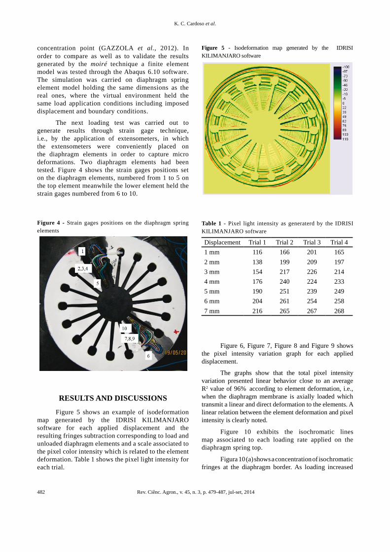
Figure 5 shows an example of isodeformationmap generated by the IDRISI KILIMANJAROsoftware for each applied displacement and theresulting fringes subtraction corresponding to load andunloaded diaphragm elements and a scale associated tothe pixel color intensity which is related to the elementdeformation. Table 1 shows the pixel light intensity foreach trial.
Table 1 - Pixel light intensity as generaterd by the IDRISIKILIMANJARO software
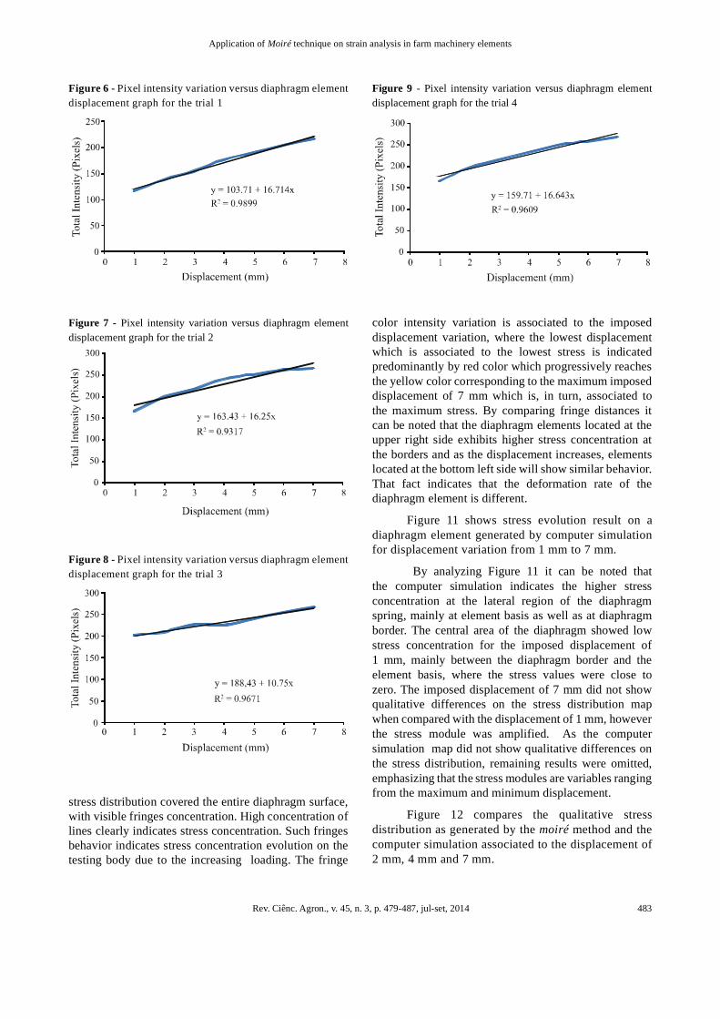
Figure 6, Figure 7, Figure 8 and Figure 9 showsthe pixel intensity variation graph for each applieddisplacement.
The graphs show that the total pixel intensityvariation presented linear behavior close to an averageR2 value of 96% according to element deformation, i.e.,when the diaphragm membrane is axially loaded whichtransmit a linear and direct deformation to the elements. Alinear relation between the element deformation and pixelintensity is clearly noted.
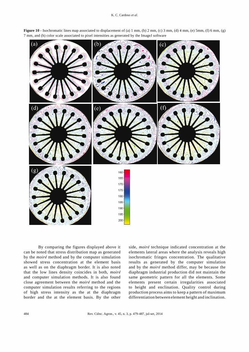
Figure 10 exhibits the isochromatic linesmap associated to each loading rate applied on thediaphragm spring top.
Figura 10 (a) shows a concentration of isochromaticfringes at the diaphragm border. As loading increased
Figure 4 - Strain gages positions on the diaphragm springelements
Figure 5 - Isodeformation map generated by the IDRISIKILIMANJARO software
Displacement Trial 1 Trial 2 Trial 3 Trial 41 mm 116 166 201 1652 mm 138 199 209 1973 mm 154 217 226 2144 mm 176 240 224 2335 mm 190 251 239 2496 mm 204 261 254 2587 mm 216 265 267 268
concentration point (GAZZOLA et al., 2012). Inorder to compare as well as to validate the resultsgenerated by the moiré technique a finite elementmodel was tested through the Abaqus 6.10 software.The simulation was carried on diaphragm springelement model holding the same dimensions as thereal ones, where the virtual environment held thesame load application conditions including imposeddisplacement and boundary conditions.
The next loading test was carried out togenerate results through strain gage technique,i.e., by the application of extensometers, in whichthe extensometers were conveniently placed onthe diaphragm elements in order to capture microdeformations. Two diaphragm elements had beentested. Figure 4 shows the strain gages positions seton the diaphragm elements, numbered from 1 to 5 onthe top element meanwhile the lower element held thestrain gages numbered from 6 to 10.
Rev. Ciênc. Agron., v. 45, n. 3, p. 479-487, jul-set, 2014 483
Application of Moiré technique on strain analysis in farm machinery elements
Figure 6 - Pixel intensity variation versus diaphragm elementdisplacement graph for the trial 1
Figure 7 - Pixel intensity variation versus diaphragm elementdisplacement graph for the trial 2
Figure 8 - Pixel intensity variation versus diaphragm elementdisplacement graph for the trial 3
Figure 9 - Pixel intensity variation versus diaphragm elementdisplacement graph for the trial 4
stress distribution covered the entire diaphragm surface,with visible fringes concentration. High concentration oflines clearly indicates stress concentration. Such fringesbehavior indicates stress concentration evolution on thetesting body due to the increasing loading. The fringe
color intensity variation is associated to the imposeddisplacement variation, where the lowest displacementwhich is associated to the lowest stress is indicatedpredominantly by red color which progressively reachesthe yellow color corresponding to the maximum imposeddisplacement of 7 mm which is, in turn, associated tothe maximum stress. By comparing fringe distances itcan be noted that the diaphragm elements located at theupper right side exhibits higher stress concentration atthe borders and as the displacement increases, elementslocated at the bottom left side will show similar behavior.That fact indicates that the deformation rate of thediaphragm element is different.
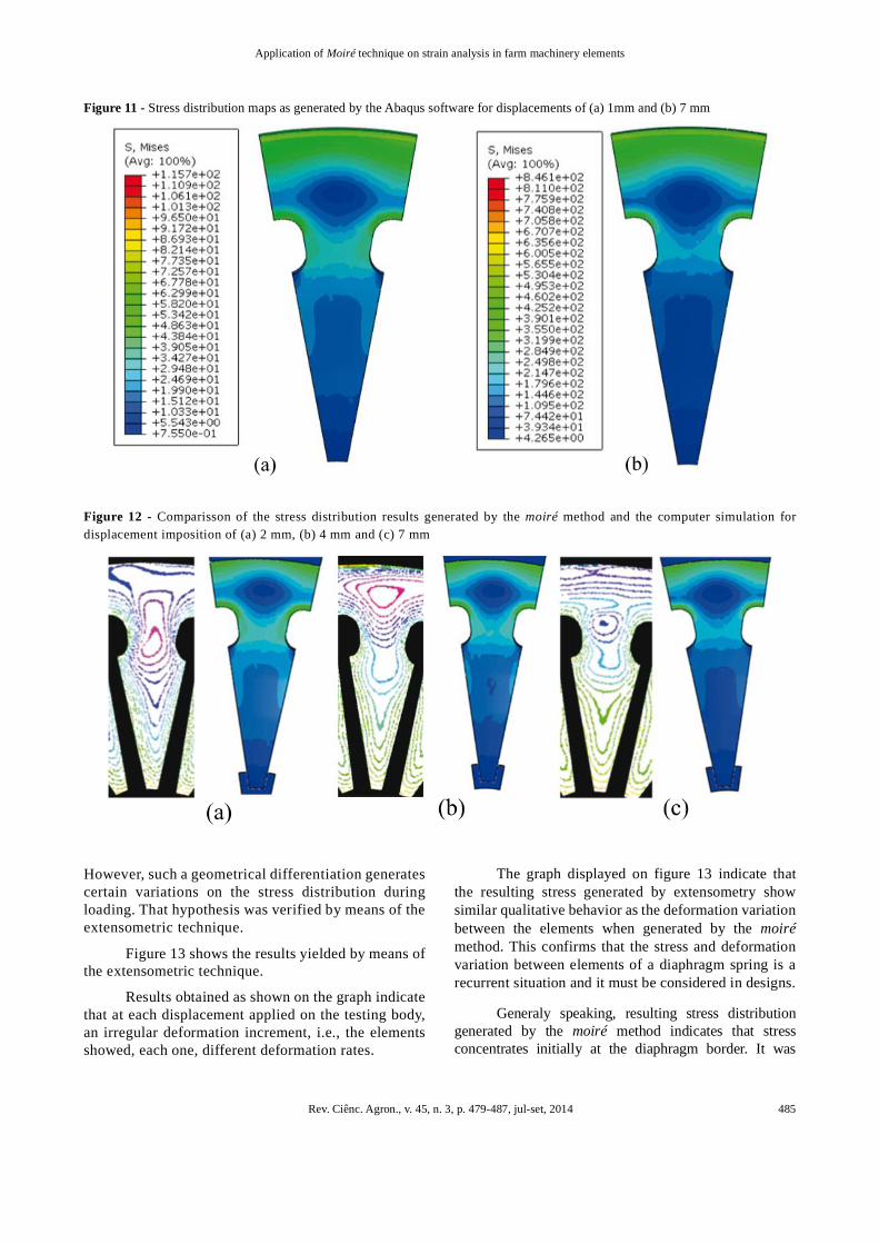
Figure 11 shows stress evolution result on adiaphragm element generated by computer simulationfor displacement variation from 1 mm to 7 mm.
By analyzing Figure 11 it can be noted thatthe computer simulation indicates the higher stressconcentration at the lateral region of the diaphragmspring, mainly at element basis as well as at diaphragmborder. The central area of the diaphragm showed lowstress concentration for the imposed displacement of1 mm, mainly between the diaphragm border and theelement basis, where the stress values were close tozero. The imposed displacement of 7 mm did not showqualitative differences on the stress distribution mapwhen compared with the displacement of 1 mm, howeverthe stress module was amplified. As the computersimulation map did not show qualitative differences onthe stress distribution, remaining results were omitted,emphasizing that the stress modules are variables rangingfrom the maximum and minimum displacement.
Figure 12 compares the qualitative stressdistribution as generated by the moiré method and thecomputer simulation associated to the displacement of2 mm, 4 mm and 7 mm.
Rev. Ciênc. Agron., v. 45, n. 3, p. 479-487, jul-set, 2014484
K. C. Cardoso et al.
side, moiré technique indicated concentration at theelements lateral areas where the analysis reveals highisochromatic fringes concentration. The qualitativeresults as generated by the computer simulationand by the moiré method differ, may be because thediaphragm industrial production did not maintain thesame geometric pattern for all the elements. Someelements present certain irregularities associatedto height and enclination. Quality control duringproduction process aims to keep a pattern of maximumdifferentiation between element height and inclination.
Figure 10 - Isochromatic lines map associated to displacement of (a) 1 mm, (b) 2 mm, (c) 3 mm, (d) 4 mm, (e) 5mm, (f) 6 mm, (g)7 mm, and (h) color scale associated to pixel intensities as generated by the ImageJ software
By comparing the figures displayed above itcan be noted that stress distribution map as generatedby the moiré method and by the computer simulationshowed stress concentration at the element basisas well as on the diaphragm border. It is also notedthat the low lines density coincides in both, moiréand computer simulation methods. It is also foundclose agreement between the moiré method and thecomputer simulation results referring to the regionsof high stress intensity as the at the diaphragmborder and the at the element basis. By the other
Rev. Ciênc. Agron., v. 45, n. 3, p. 479-487, jul-set, 2014 485
Application of Moiré technique on strain analysis in farm machinery elements
Figure 11 - Stress distribution maps as generated by the Abaqus software for displacements of (a) 1mm and (b) 7 mm
Figure 12 - Comparisson of the stress distribution results generated by the moiré method and the computer simulation fordisplacement imposition of (a) 2 mm, (b) 4 mm and (c) 7 mm
However, such a geometrical differentiation generatescertain variations on the stress distribution duringloading. That hypothesis was verified by means of theextensometric technique.
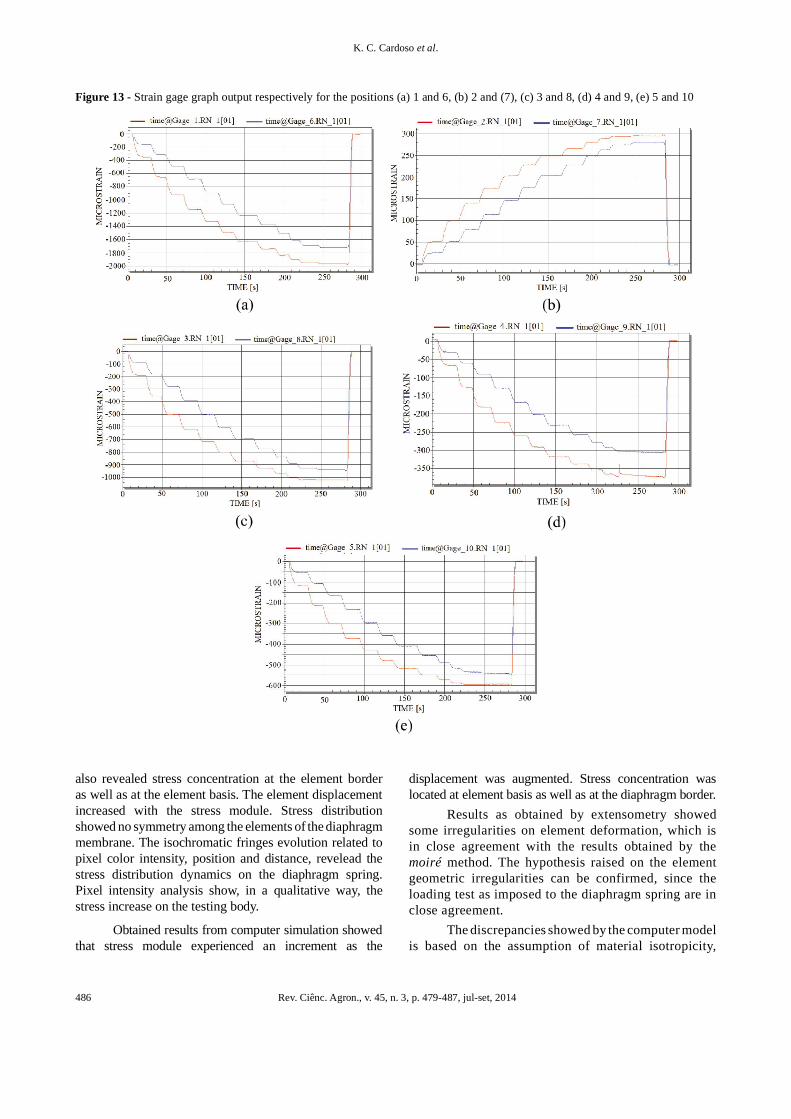
Figure 13 shows the results yielded by means ofthe extensometric technique.
Results obtained as shown on the graph indicatethat at each displacement applied on the testing body,an irregular deformation increment, i.e., the elementsshowed, each one, different deformation rates.
The graph displayed on figure 13 indicate thatthe resulting stress generated by extensometry showsimilar qualitative behavior as the deformation variationbetween the elements when generated by the moirémethod. This confirms that the stress and deformationvariation between elements of a diaphragm spring is arecurrent situation and it must be considered in designs.
Generaly speaking, resulting stress distributiongenerated by the moiré method indicates that stressconcentrates initially at the diaphragm border. It was
Rev. Ciênc. Agron., v. 45, n. 3, p. 479-487, jul-set, 2014486
K. C. Cardoso et al.
Figure 13 - Strain gage graph output respectively for the positions (a) 1 and 6, (b) 2 and (7), (c) 3 and 8, (d) 4 and 9, (e) 5 and 10
also revealed stress concentration at the element borderas well as at the element basis. The element displacementincreased with the stress module. Stress distributionshowed no symmetry among the elements of the diaphragmmembrane. The isochromatic fringes evolution related topixel color intensity, position and distance, revelead thestress distribution dynamics on the diaphragm spring.Pixel intensity analysis show, in a qualitative way, thestress increase on the testing body.
Obtained results from computer simulation showedthat stress module experienced an increment as the
displacement was augmented. Stress concentration waslocated at element basis as well as at the diaphragm border.
Results as obtained by extensometry showedsome irregularities on element deformation, which isin close agreement with the results obtained by themoiré method. The hypothesis raised on the elementgeometric irregularities can be confirmed, since theloading test as imposed to the diaphragm spring are inclose agreement.
The discrepancies showed by the computer modelis based on the assumption of material isotropicity,
Rev. Ciênc. Agron., v. 45, n. 3, p. 479-487, jul-set, 2014 487
Application of Moiré technique on strain analysis in farm machinery elements
continuity as well as regularity , which are not assumedby the extensometry, nor by the moiré method. In otherwords, moiré and extensometry assume the body toexhibit real behavior.
The absence of variation on elements deformationresults indicated by computational simulation hasbeen occurred because this technique analyzes partscharacterized to be isotropic, homogeneous, continuousand unique geometry between elements. But, moiréand extensometric techniques, which demonstratedsuch variations, results have been generated on testingbody with geometry variation between elements andmaterial irregularities.
CONCLUSION
Based on what it has been explained before,it can be concluded that the shadow moiré techniquecan be considered as a profile measuring method ofmechanical analysis which can generate reliable resultsin determining qualitative stress distribution on machineelements of complex geometry. Results generated bythe shadow moiré method corresponded to the expectedresults as obtained by extensometry. The simplicityshowed by the above referred method turn it attractive tothe experimental mechanics study as well as to industrialapplications. Stress and deformation quantificationstudies are recommended for future studies.
REFERENCESALBIERO, D. et al. Moiré Optical Technique For EvaluationOf Cashew Nuts (Anacardium Occidentale, L.) Isostrain.Varia Scientia Agrarias, v. 2, n. 2, p. 9-20, 2012.
ANDONIAN, A. A. T. Optical Methods. Springer Handbookof Solid Mechanics. New York: Sharpe, 2008. p. 823-837.
BASTOS, L. F.; TAVARES, J. M. R. S. Um sistema deferramentas de processamento e análise de imagens de moiré:apresentação. In: ENCONTRO NACIONAL DE ANÁLISEDE TENSÕES E MECÂNICA EXPERIMENTAL, 5., 2004,Coimbra. Anais... Coimbra: APAET, 2004.
BERALDO, A. L. et al. Técnica de moiré aplicada al análisisde esfuerzos de compresión en el bambu guadua. Maderas:Ciencia y Tecnologia Concepción, v. 9, n. 3, p. 309-322, 2007.
BRAGA, R. A. et al. Supression of border effects in moirétechniques using three-dimensional methods. BiosystemsEngineering, v. 102, n. 1, p. 1-8, 2009.
COSTA, R. M. et al. Sensitivity of the moiré technique formeasuring biological surfaces. Byosistem Engineering, v. 100,n. 3, p. 321-328, 2008.
DOYLE, J. F. Hybrid Methods. Springer Handbook of SolidMechanics. New York: Sharpe, 2008.
GAZZOLA, J. et al. Shadow Moiré Applied to TorsionalStress Distribution Mapping. Agricultural EngineeringJournal, v. 48, n. 2, p. 61-65, 2010.
GAZZOLA, J. et al. Photomechanical analysis of wooden testingbodies under flexural loadings. World Academy of Science,Engineering and Technology, v. 70, p. 396-401, 2012.
GOMES, T. S. et al. Calibração da técnica de moiré aplicadaa perfilometria de protótipos mecânicos. Revistas Ciência eAgrotecnologia, v. 33, n. 2, p. 574-579, 2009.
GLEICE, C. A. et al. Recuperação de Topografia de Ovospor Meio da Técnica de Moiré e Calibração Independente.Engenharia Agrícola. v. 31, n. 2, p. 211-218, 2011.
KUNINARI, F. et al. Moiré aided soil-tractor tire contact areaand contact volume determination. Journal of AgriculturalMachinery Science, v. 4, n. 1, p. 39-43, 2008.
LEI, Z.; YUN, H.; YUN, D.; KANG, Y. Numerical analysisof phase-stepping interferometric photoelasticity for planestress separation. Optics ans Laser in Engineering, v. 45,n. 1, p. 77-82, 2007.
LINO, A. C. L.; DAL FABBRO, I. M. Determinação datopografia de uma fruta pelas técnicas de moiré de sombracom multiplicação de franjas. Revista Ciência Agrotécnica.v. 28, n. 1, p. 119-125, 2004.
MAZZETI FILHO, V. et al. Application of a Moiré techniquein the stress distribution mapping of circular rotors. RevistaCiência e Tecnologia, ano 7, n. 10, p. 31-34, 2004.
PORTO, F.; GURGEL, J. L.; FARINATTI, P, T, V. Topografiade Moiré como Método de Avaliação Postural: Revisãodo Estado da Arte. Revista Brasileira de Geriatria eGerontologia, v. 3, n. 14, p. 567-577, 2011.
RI, S.; FUJIGAKI, M.; MORIMOTO, Y. Sampling Moiré Methodfor Accurate Small Deformation Distribution Measurement.Experimental Mechanics. v. 50, n. 4, p. 501-508, 2010.
RYU, W. et al. A Study on the 3-D Measurement by UsingDigital Projection Moiré Method. Optik - InternationalJournal for Light and Eletron Optics. v. 119, n. 10, p. 453-458, 2008.
SPINELLI, H. A.; SILVA, F. A. Aplicação da Fotoelasticidade naAnálise Estrutural de uma Junta Rebitada de Uso Aeronáutico.2003, Guaratinguetá. Anais... Guaratinguetá, 2003.
XIAO, X. et al. Displacement and Strain Measurement byCircular and Radial Gratings Moiré Method. ExperimentalMechanics, v. 50, n. 2, p. 239-244, 2010.