112
DOCUMENTATION OF THE TRESTLE at Kirtland Air Force Base, New Mexico NOVEMBER 2003 Prepared by: Van Citters: Historic Preservation, LLC 7007 Prospect Place NE Albuquerque, NM 87110
DOCUMENTATION
OOFF TTHHEE TTRREESSTTLLEE
aatt KKiirrttllaanndd AAiirr FFoorrccee BBaassee,, NNeeww MMeexxiiccoo
NOVEMBER 2003
Prepared by: Van Citters: Historic Preservation, LLC
7007 Prospect Place NE Albuquerque, NM 87110

DDOOCCUUMMEENNTTAATTIIOONN
OOFF TTHHEE TTRREESSTTLLEE
aatt
KKiirrttllaanndd AAiirr FFoorrccee BBaassee,, NNeeww MMeexxiiccoo
TRESTLE logo from an early user brochure. Source: AFWL n.d. g
Cover photo from DTRIAC TRESTLE Collection
Written by: Karen Van Citters, CSI, CDT
Deborah Butcher
Prepared under DACA45-01-D-0010
In cooperation with e2M, Inc.
1510 West Canal Court Suite 2000
Littleton, Colorado 80120
Documentation of TRESTLE
i
Van Citters: Historic Preservation, LLC Project No. 195-03
TABLE OF CONTENTS
LIST OF ACRONYMS & ABBREVIATIONS............................................................................ iv I. Introduction......................................................................................................................... 1 II. Administrative Summary .................................................................................................... 3 III: Historical Information......................................................................................................... 5 IV. TRESTLE Description........................................................................................................ 6 V. Historical Narrative............................................................................................................. 9
The Cold War and the Limited Test Ban Treaty......................................................................... 9 Atmospheric Tests and the Limited Test Ban Treaty ........................................................... 10 EMP Simulation.................................................................................................................... 10
Simulator Design at AFWL ...................................................................................................... 13 Simulator Construction and Figures of Merit ....................................................................... 13 Types of EMP Simulators..................................................................................................... 16 Simulator Construction Program at Kirtland AFB ............................................................... 18 Requirement for “In-Flight” Simulator................................................................................. 19
TRESTLE Conceptual Design.................................................................................................. 20 AFWL Design Development ................................................................................................ 20 Contractor Designs................................................................................................................ 22
The Air Force Program for TRESTLE Construction................................................................ 23 TRESTLE Contracting and Program Realignment................................................................... 27 TRESTLE Design Issues .......................................................................................................... 40
Site Selection ........................................................................................................................ 40 Dielectric Materials Selection............................................................................................... 43 Structural Loads and Design/Construction Issues ................................................................ 45 TRESTLE Electromagnetic Environment Features.............................................................. 53 TRESTLE Pulser Development............................................................................................ 60 Completion, Facility Checkout, and Transition.................................................................... 63
Transition to Operation and the Test Program.......................................................................... 65 Program Organization for Operations and Testing Phase..................................................... 67 O&M at TRESTLE............................................................................................................... 69
End of the Cold War and End of Simulator Operations ........................................................... 71 GLOSSARY ................................................................................................................................. 73 REFERENCES CITED................................................................................................................. 75 APPENDIX A: EXTANT DIPOLE SIMULATORS................................................................... 89 APPENDIX B: EXTANT HYBRID SIMULATORS .................................................................. 91 APPENDIX C: EXTANT GUIDED WAVE SIMULATORS ..................................................... 93 APPENDIX D: U.S. SIMULATORS BUILT DURING THE COLD WAR............................... 95 APPENDIX E: MDAC SUBCONTRACTORS ........................................................................... 98 APPENDIX F: TRESTLE PROGRESS DATA......................................................................... 100 APPENDIX G: 1976 TRESTLE TASKS................................................................................... 102

Documentation of TRESTLE
ii
Van Citters: Historic Preservation, LLC Project No. 195-03
List of Figures
Figure 1: Radius of high altitude EMP effects................................................................................ 2 Figure 2: TRESTLE........................................................................................................................ 6 Figure 3: Construction of Glue-laminated bent .............................................................................. 7 Figure 4: Geometry of a high altitude burst.................................................................................. 13 Figure 5: ACHILLES Simulators ................................................................................................. 15 Figure 6: ATHAMAS Simulators................................................................................................. 15 Figure 7: ARES Simulator ............................................................................................................ 15 Figure 8: RES-I in flight ............................................................................................................... 16 Figure 9: ACHILLES I (VPD-I) ................................................................................................... 18 Figure 10: Conceptual View of Aircraft on Trestle-type simulator.............................................. 20 Figure 11: Torus concepts............................................................................................................. 21 Figure 12: Bounded wave simulator concept................................................................................ 22 Figure 13: Conceptual Design for Platform.................................................................................. 22 Figure 14: Plan View of B-52 dimensions.................................................................................... 23 Figure 15: 1974 Organization Chart ............................................................................................. 33 Figure 16: Changes to TRESTLE Program .................................................................................. 37 Figure 17: TRESTLE during construction.................................................................................... 38 Figure 18: Detail of the deck construction.................................................................................... 39 Figure 19: Delivery of Beams....................................................................................................... 40 Figure 20: Sites considered for TRESTLE ................................................................................... 41 Figure 21: Field Geometry for TRESTLE Simulator Wood Members ........................................ 44 Figure 22: Construction Modules and Joints ................................................................................ 46 Figure 23: Split-Ring Connector................................................................................................... 46 Figure 24: TRESTLE bolt detail................................................................................................... 47 Figure 25: TRESTLE components................................................................................................ 54 Figure 26: TRESTLE Geometry (Design 5)................................................................................. 54 Figure 27: Ground Plane design for TRESTLE............................................................................ 56 Figure 28: Pulser waveform.......................................................................................................... 58 Figure 29: Pulsers before installation on simulator ...................................................................... 62 Figure 30: B-52 on the TRESTLE................................................................................................ 65 Figure 31: A Schematic Design for the Fire Protection System................................................... 68 Figure 32: TRESTLE data system block diagram ........................................................................ 71
List of Tables
Table 1: Proposed TRESTLE Components .................................................................................... 7 Table 2: Types of EMP simulators ............................................................................................... 16 Table 3: B-52 Characteristics........................................................................................................ 24 Table 4: C3 aircraft to be tested at TRESTLE............................................................................... 25 Table 5: TRESTLE Staff .............................................................................................................. 27 Table 6: Inflation effects on TRESTLE........................................................................................ 28 Table 7: TRESTLE Construction Timeline .................................................................................. 39 Table 8: TRESTLE Components and Capacities.......................................................................... 63

Documentation of TRESTLE
iii
Van Citters: Historic Preservation, LLC Project No. 195-03
Table 9: Test Phases...................................................................................................................... 66 Table 10: Some of the aircraft tested at TRESTLE ...................................................................... 69
Documentation of TRESTLE
iv
Van Citters: Historic Preservation, LLC Project No. 195-03
LIST OF ACRONYMS & ABBREVIATIONS AABNCP Advanced Airborne National Command Post ACHILLES AFWL Characterization Interim Low Level Electromagnetic Pulse Simulator AFB Air Force Base AFM Air Force Manual AFR Air Force Regulation AFRL Air Force Research Laboratory AFSC Air Force Systems Command AFSWC Air Force Special Weapons Center AFSWP Armed Forces Special Weapons Project AFWL Air Force Weapons Laboratory ALECS Los Alamos Scientific Laboratory EMP Calibration and Simulation APA American Plywood Association ARES AFWL RAND EMP simulator ASTM American Society for Testing and Materials ATHAMAS AFWL Terrestrial High-Altitude EMP Alert Mode Aircraft Simulator ATLAS AFWL Transmission Line Aircraft Simulator (TRESTLE) AWACS Airborne Warning and Control System BDM Braddock, Dunn, and McDonald, Inc. BDMMSC BDM Management Services Company C3 command, control and communication CD compact disk CDR Critical Design Review CO Contracting Officer DCAS Defense Contract Administration Service DSB Defense Science Board DPS data processing system DTRIAC Defense Threat Reduction Information Analysis Center EAC estimate at completion ECP engineering change procedure EG&G EG&G Incorporated EMP electromagnetic pulse EVS electro-optical viewing system FAA Federal Aviation Administration FCC Federal Communications Commission FPL Forest Product Laboratory ft feet FY fiscal year GFE government furnished equipment GFP government furnished property GHz gigahertz HAER Historic American Engineering Record HEMP high-altitude electromagnetic pulse
Documentation of TRESTLE
v
Van Citters: Historic Preservation, LLC Project No. 195-03
HSI Hardness Surveillance Illuminator HPD Horizontally Polarized Dipole HQ headquarters ICBM Intercontinental Ballistic Missile IEC International Electrotechnical Commission in inches IOC Initial Operating Capability IRBM Intermediate Range Ballistic Missile KAFB Kirtland Air Force Base Krause R.D. Krause Engineering Company kV kilovolt LASL Los Alamos Scientific Laboratory lb pound L-R LTBT Limited Test Ban Treaty MDAC McDonnell Douglas Aircraft Company m meters MHz megahertz MLI Maxwell Laboratories, Inc. mph miles per hour MV megavolt NASTRAN NASA Structural Analysis System NDS National Design Specification for Stress-Grade Lumber and Its Fastenings NEACP National Emergency Airborne Command Post NORAD North American Aerospace Defense Command NSC National Security Council Ω Ohms O&M Operation & Management PMAT Program Management Assistance Team PMD Program Management Directive psi pounds per square inch PTF Pulser Test Fixture R&D research and development RES radiating EMP simulator RFP Request for Proposal ROM rough order of magnitude SAC Strategic Air Command SDF Siege Development Facility SF6 Sulfur Hexaflouride SIEGE Simulated EMP Ground Environment SRAM short-range attack missile TACAMO “Take Charge and Move Out” EC-130Q TEM transverse electric and magnetic TP TRESTLE Program Office UBC Uniform Building Code
Documentation of TRESTLE
vi
Van Citters: Historic Preservation, LLC Project No. 195-03
USAF United States Air Force VCHP Van Citters: Historic Preservation, LLC VPD Vertically Polarized Dipole Wedge Central Ground Plane Wedge
Documentation of TRESTLE
1
Van Citters: Historic Preservation, LLC Project No. 195-03
I. INTRODUCTION Location: East of the runway at Kirtland Air Force Base, New Mexico Quad: Albuquerque East UTM: 13 357947E 3877268N (NAD27) Date of Construction: 1972 – 1980 Present Owner: Kirtland Air Force Base; 377th Air Base Wing Present Use: Offices for the U.S. Army “Big Crow” Program in the Ground
Plane Wedge Significance: At the end of World War II, the U.S. began a series of atmospheric tests in order to maintain nuclear superiority over Russia. During these tests, scientists and the military noticed that there was an electromagnetic pulse (EMP) created by the explosion of a nuclear weapon and that this pulse had a negative effect on military systems. After the atmospheric test bans in the early 1960s, scientists and the military began to develop alternative methods to evaluate nuclear weapons and their effects, including EMP. During this post test-ban period, a number of EMP simulators to test aircraft were developed by the Air Force Weapons Laboratory (AFWL) at Kirtland Air Force Base (AFB). EMP simulation was developed to create an environment similar to that which would occur in the upper atmosphere in the event of a nuclear detonation. Nuclear explosions produce gamma rays, which create EMP when they interact with the atmosphere. The gamma rays essentially ionize the atmosphere and produce electrical fields: the currents flowing through those fields are EMP. In the late 1950s during the atmospheric tests, the military began to understand that EMP incapacitates electronics. The first recorded EMP incident occurred during a high-altitude nuclear test in the Marshall Islands and resulted in power system failures as far away as Hawaii (Federation of American Scientists 2003:1). If a detonation took place 200 miles above southern Canada, because of the orientation of the earth’s magnetic field, EMP effects would cover nearly the entire United States (U.S.), with the potential to incapacitate electronics throughout the entire country (AFWL 1983-1984:200) (Figure 1). Because the modern military has a heavy reliance on solid-state electronics, the phenomenon of EMP was of great interest to the nuclear effects community in the AFWL. The need for EMP simulators became stronger as electronics evolved from vacuum tubes to solid-state components to microelectronics; these advancements in technology made the systems more susceptible to EMP (HQ USF 1973:1). As a result, AFWL began to test for EMP and work towards developing means to “harden” or protect systems against the EMP that would result from a nuclear attack in efforts to ensure “survivability.”

Documentation of TRESTLE
2
Van Citters: Historic Preservation, LLC Project No. 195-03
Figure 1: Radius of high altitude EMP effects
The largest simulator constructed was the AFWL Transmission Line Aircraft Simulator (ATLAS), which is commonly known as the TRESTLE. In order to properly test large aircraft in a simulated flight mode, the simulator was constructed of wood, a material that would not conduct electricity. This was required so that the structure would have minimal impact on the EMP environment created to test the aircraft. The test article also had to be sufficiently high above the ground to avoid ground interference with the EMP current in order to simulate the in-flight environment. As such, the TRESTLE was constructed with a raised test platform and of wood glue-laminated trusses connected with wood bolts. It is twelve stories tall and 1,000 feet (ft) long and is said to be the largest all wood structure in the world.

Documentation of TRESTLE
3
Van Citters: Historic Preservation, LLC Project No. 195-03
II. ADMINISTRATIVE SUMMARY Historian: Van Citters: Historic Preservation, LLC (VCHP) Date of Research: August 2003 Sources Searched: Air Force Research Laboratory Phillips Research Site Historical
Information Office Defense Threat Reduction Agency Information Center 377th Air Base Wing Environmental Management files 377th Air Base Wing Civil Engineering Drawing files Dr. Carl Baum, Air Force Research Laboratory, Directed Energy Directorate, High Power Microwave Division Bill Prather, Air Force Research Laboratory, Directed Energy Directorate, High Power Microwave Division
Methodology: Van Citters: Historic Preservation, LLC (VCHP) contacted the Air Force Research Laboratory (AFRL) Phillips Research Site Historical Information Office for data about TRESTLE and they provided copies of photographs and other information available at their archive. VCHP conducted research in the drawing files of the 377th Air Base Wing, Civil Engineering and copied a number of drawings that were useful in describing TRESTLE and some of the design changes that took place during construction. The Defense Threat Reduction Agency Information Center (DTRIAC) allowed the team to conduct research at their facility for unclassified information available on the ATLAS facility. This information consisted of eighteen boxes of TRESTLE information from the AFRL Phillips Research Site Historical Information Office that had been sent to DTRIAC for archival storage. Video and reel-to-reel audiotapes were located in the DTRIAC archive. The videotapes were copied for use in the documentary that accompanies this written document. The audiotapes consisted of interviews of TRESTLE staff taken in 1980 by Dr. Robert Duffner of the AWFL History Office. VCHP had the tapes transferred to compact disk (CD) and the CDs transcribed for use in this project. VCHP also interviewed Dr. Carl Baum of the AFRL Directed Energy Directorate, scientist/designer for the ATLAS facility. He provided the team with diagrams, background data, and historic photographs. William Prather of AFRL Directed Energy Directorate also provided data for the project. Laser Geomatics was contracted to create measured drawings and a 3-D model of the facility through laser scanning. The TRESTLE was scanned with a ** to create a point cloud model in the field then the point data was used by drafters to create a 3-D computer model. This model was then used to develop the 2-D Historic American Engineering Record (HAER) drawing set.

Documentation of TRESTLE
4
Van Citters: Historic Preservation, LLC Project No. 195-03
Avista Video Histories was contracted to develop a 30-minute documentary of the TRESTLE. The documentary includes information about the genesis of the idea for the TRESTLE, EMP, and construction and interviews with people involved in the project and testing at the facility. Concurrently there was documentation with HAER formal photography (4 x 5 format) of the ATLAS property.

Documentation of TRESTLE
5
Van Citters: Historic Preservation, LLC Project No. 195-03
III: HISTORICAL INFORMATION Feasibility Studies:
1) AFWL scientists and EG&G Incorporated completed a TRESTLE Design Study.
General Contractor: 1) McDonnell Douglas Astronautics Co.: overall integrating contractor for the TRESTLE
program.
Architectural & Engineering Firms: 1) Stadelmann Engineering, Inc.: consultant on glue-laminated timber structures (contract
with AFWL). 2) W.C. Kruger & Associates: architectural and engineering design (subcontract to Mc
Donnell Douglas Astronautics Co.). 3) R. D. Krause Engineering Company at Santa Fe: structural design 4) Culbertson, Noren & Neal: Title II architect-engineer inspection services for the test
stand (contract with AFWL). 5) Shirmer Engineering Corporation: design of the fire protection system (contract with
AFWL). Test Stand and Ramp Construction: 1) Hunt Building Company: construction of caissons. 2) Allen M. Campbell Company of Tyler, Texas: construction of wood ramp, wood
terminator stand, two wood pulser stands, test stand, walkway and transmission line subsystem.
3) Standard Structures Inc.: construction of glue-laminated timbers. 4) Woodlam, Inc.: construction of glue-laminated beams. Pulser and Test System Design/Construction: 1) Maxwell Laboratories, Inc.: pulser design and construction. 2) Braddock, Dunn and McDonald: electromagnetic analysis, timing and control equipment
(subcontract to McDonnell Douglas Astronautics Co.). 3) Black & Veatch: design of the Test Article Support System.
Documentation of TRESTLE
6
Van Citters: Historic Preservation, LLC Project No. 195-03
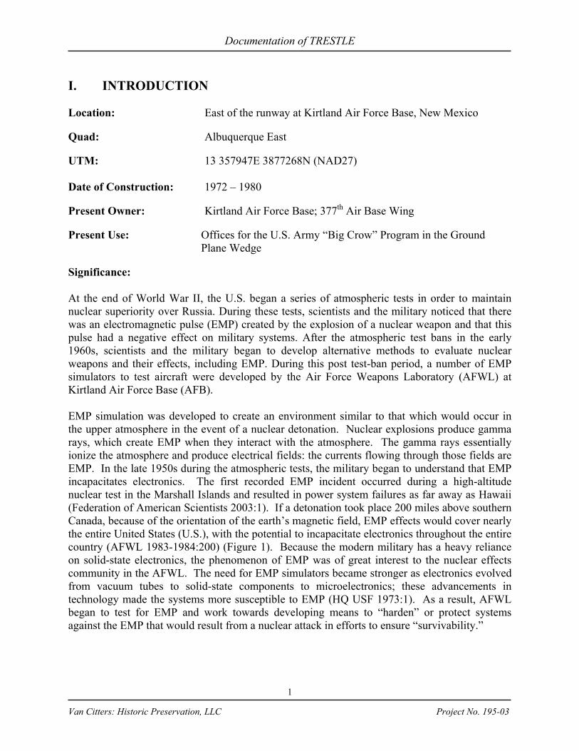
IV. TRESTLE DESCRIPTION TRESTLE was constructed to test large aircraft for the effects of EMP and simulated an “in-flight” environment. To do so the facility was constructed well above grade of an electrically non-conducting material (dielectric), with a system that would develop a pulse that would result in an electromagnetic wave. The dielectric material selected for construction was glue-laminated lumber and the structure was constructed in an arroyo (drainage), an area where the grade naturally dropped off, which facilitated creating a tall structure above grade onto which a plane could be towed. The TRESTLE included a towpath from the runway to the site, a wood ramp that served to move the plane from grade into testing position, a test stand 115 feet (ft) or 35 meters (m) above grade that served to support the plane as it was subjected to EMP, and the
Central Ground Plane Wedge (Wedge) (Figure 2). The ramp, which leads from the towpath to the test stand, is 400 ft long by 50 ft wide. The test stand was designed as a 200-ft square, but in order to reduce construction costs, a thirty-by-thirty ft square, that did not affect the turning radius of aircraft to be tested, was removed from each corner of the structure. The ramp and test stand are separate structures, in that they are not pinned or fixed to each other (USAF 23 August 1978). Figure 2: TRESTLE Source: DTRIAC TRESTLE Collection
The Wedge is at the south end of the structure and housed the control room and offices and the support structure for the pulsers that created the EMP. The steel structure that rises from the building is covered with wire mesh and served as a portion of the transmission line (Cole July 1976:3). The Wedge was the control center for TRESTLE operations. It has four levels, each served by an elevator and two outside stairways. The first and second levels are walled-in to provide habitable office, storage and work areas. The third and fourth levels are semi-protected from both the weather and the electromagnetic field environments. The fourth level was called the pulser level and personnel were excluded from this level in the area immediately adjacent to the two pulsers during pulser firing operations (AFWL 22 July 1977:2-20). The structural design was completed by R.D. Krause Engineering at Santa Fe (Krause) and W.C. Kruger & Associates at Albuquerque, under a subcontract with McDonnell Douglas Aircraft Company (MDAC) (Koppers 1977:3). Originally, the TRESTLE was composed of individual wood truss columns. The final design was more of a standard trestle bent with braces

Documentation of TRESTLE
7
Van Citters: Historic Preservation, LLC Project No. 195-03
interconnecting the structure throughout. The bent structure was designed to withstand a wind load capacity of 40 miles per hour (mph) (Program Management Assistance Team 1975:3). Figure 3 shows a bent during construction.
Figure 3: Construction of Glue-laminated bent
Source: DTRIAC TRESTLE Collection The pulses at TRESTLE were created by a pulser and a parallel plate transmission line: running north to south on the east and west side of the test stand and ramp. The pulser at the south end produced the high amplitude, nanosecond pulse. The pulse source consisted of two Marx generators housed in 1,600 cubic ft airtight enclosures – one on the east and one on the west – that would launch the pulse wave into the transmission lines. The Marx generators included a bank of capacitors with each capacitor charging to 50 kilovolts (kV). The switching mechanism in the banks allowed the voltage on each capacitor to multiply in such a manner that the output was on the order of 5 million volts, or megavolts (MV), for each generator. Once a bank was charged they would be rapidly switched to discharge into the transmission line (Cole July 1976:2). The generator enclosures were filled with Sulfur Hexaflouride (SF6), a pressurized electronegative gas that would prevent high voltages from arcing to the ground (Cole July 1976: 1–3, 14). Each transmission line comprised a wire array on a vertical alignment supported by masts. Although the wire arrays are not solid, they acted as plates below a “certain frequency.” At the test stand, the arrays are parallel, but they taper and angle toward the TRESTLE structure at the north and south. These tapers were the transition sections that provided the electrical connection and termination. In order to reduce electromagnetic reflections onto the test stand, which could adversely affect a test, a termination was required to dissipate the energy (Cole July 1976:3). A 127 ft tower with an energy absorbing resistive array at the north end housed the electromechanical termination device. Table 1 shows the dimensions for the proposed structure that AFWL provided during a presentation to the American Timber Industry (Slater March 1975:4-6). Table 1: Proposed TRESTLE Components
Source: Slater March 1975
TRESTLE Component Dimension Length – Wedge to terminator 1300 ft or 4 football fields

Documentation of TRESTLE
8
Van Citters: Historic Preservation, LLC Project No. 195-03
TRESTLE Component Dimension Width – rim to rim of bowl 600 ft or 2 football fields Depth of bowl Approximately 120 ft Transmission tower height 185 ft (68 ft are glue laminated) Wedge – length 250 ft long x 240 ft high Ramp 50 ft x 400 ft x 12 ft up to 115 ft high Test Stand 200 ft x 200 ft x 115 ft high Walkway 10 ft x 80 ft x 115 ft high Pulser Support (2) 30 ft x 70 ft x 74 ft high Terminator Support 36 ft x 62 ft x 127 ft high Tower poles (6 each) 26 in x 26 in x 68 ft high Total glue-laminated material 6.5 million board ft Number of joints 10,000 Dielectric bolts 60,000 Split rings and shear plates 120,000 Square feet of gusset plates 12,000

Documentation of TRESTLE
9
Van Citters: Historic Preservation, LLC Project No. 195-03
V. HISTORICAL NARRATIVE The Cold War and the Limited Test Ban Treaty The “Cold War,” as journalist Walter Lippman first coined it (Primary Sources n.d.), continued from the end of World War II in 1945 to 1989 when the fall of the Berlin Wall essentially ended the conflict. After the World War II defeat of Japan, the U.S. relationship with Russia changed dramatically for the worse. Polarization of the political ideologies transformed the former atmosphere of alliance to one of distrust. This distrust spawned the need for strategic deterrence and atomic weapons became the ultimate means of that deterrence. Although the Soviet Union did not detonate an atomic weapon until 1949, the Cold War began with the testing of the first atomic bomb at the Trinity Site in July 1945. The nuclear weapon, which stunned the world with its decimation of Hiroshima and Nagasaki, became the means for deterrence of a third world war as the U.S. and the Soviet Union focused on production of warheads. Although the growing concept of deterrence through strength in military technology was in existence before the dropping of the atomic bombs on Japan, immediately postwar it came to the forefront of both countries’ strategy and policy. The incorporation of deterrence into national policy and strategy became the primary force behind the escalation of the arms race. In late 1949, the U.S. National Security Council (NSC) declared deterrence as the national military strategy (Lewis et. al. 1995:29). NSC Document No. 68 (NSC-68) of 1950 stated that the Soviet Union was bent on world domination and that by 1954 would equal the U.S. in atomic capability. NSC-68 recommended a massive military build-up. In August of 1953, the Soviet Union detonated its first hydrogen bomb and Soviet scientists began working on the world’s first Intercontinental Ballistic Missile (ICBM), called the R-7. Later in the year, the R-7 was equipped to carry a nuclear warhead, resulting in the U.S. reassessing its ability to deter the possibility of a Soviet first-strike attack (Gaither, 1997:13; Lewis et. al. 1995:32). The 1954 Killian Report or “Surprise Attack Study” recommended that the highest national priority be placed on the development of the U.S. Air Force ICBM program, Intermediate Range Ballistic Missile (IRBM) capabilities for land and shipboard launch, construction of an early warning system in the Arctic, and R&D for a possible anti-missile system. Further incentive to arm came when the Soviets launched Sputnik I and II satellites into Earth orbit in 1957. The ramification of this event was that if the Soviets could launch a satellite into space they had the capability to launch a hydrogen warhead 5,000 miles, a capability that the U.S. did not have at the time. The military strategy of the U.S. under President Eisenhower became one of massive retaliation. The early 1960s were marked by several crises, including the building of the Berlin Wall, the Bay of Pigs, and the Cuban Missile Crisis. Each of these events was different in scale and cumulated in a new view of the use of nuclear weapons. The strategy changed to the potential

Documentation of TRESTLE
10
Van Citters: Historic Preservation, LLC Project No. 195-03
selective use of nuclear weapons in the event that deterrence failed and use of massive nuclear force only in retaliation for a first-strike (Lewis et al. 1995:40).
Atmospheric Tests and the Limited Test Ban Treaty Beginning in 1946 with Operation Crossroads, the U.S. conducted numerous atmospheric nuclear weapons tests to learn how to maximize the effects of atomic weapons, gather information about the environment created by their detonations, and test their effects on living beings and military equipment (Defense Threat Reduction Agency 2001). The atmospheric tests conducted through the 1950s were critical to the definition of nuclear weapons effects for the design of survivable U.S. offensive and defensive weapons systems. During late 1958, both the U.S. and the Soviet Union voluntarily suspended nuclear weapons testing. In reaction to the Soviet Union detonation of a nuclear device in the atmosphere in 1961, the U.S. resumed testing and continued until the U.S., United Kingdom, and Soviet Union signed the Limited Nuclear Test Ban Treaty (LTBT) in 1963. The 1963 LTBT effectively ended nuclear weapons tests or any other nuclear explosion in the atmosphere, in outer space, and under water (underground testing was still permitted). In light of the moratorium, the U.S. began to look to simulation methods to determine the effects of nuclear blasts on military materiel. Nuclear explosions produce radiation effects on equipment ranging from weapons storage structures to electronics. Two types of simulation, one to test hardness of structures and the other to test the effects of EMP, were conducted at Kirtland AFB in Albuquerque under the Air Force Special Weapons Center (AFSWC), which was established in 1952 to ensure the atomic capability of aircraft and missiles. Establishing AFSWC at Kirtland AFB was a logical choice. At the end of World War II, Albuquerque had become home to the following groups working with nuclear weapons:
1) Z Division, a weapons research group that had moved from Los Alamos and eventually became Sandia Laboratory;
2) Manzano Base nuclear stockpile; 3) Air Force Special Weapons Command, which oversaw the testing development
for nuclear weapons; and 4) Armed Forces Special Weapons Project (AFSWP), a group with representatives
from the Army, Navy, and Air Force. As the LTBT began to have an effect on how the U.S. evaluated their nuclear capabilities and ability to respond to a nuclear attack, the focus of efforts at the Albuquerque military and research facilities began to shift to simulation. EMP Simulation In the early part of the Cold War, as open air nuclear tests were taking place, the military began to realize that a by-product of nuclear explosions was EMP. EMP is detrimental to electronics and develops when the gamma rays from a nuclear explosion interact with the atmosphere: the

Documentation of TRESTLE
11
Van Citters: Historic Preservation, LLC Project No. 195-03
gamma rays ionize an area of the atmosphere (known as the source region) and produce an electric field. The currents that flow through that field are EMP; those currents reach their peak in a few to 10 nanoseconds, and although they peak in such a short period, they are very powerful and can spread at the speed of light. In a high altitude burst, EMP extends in all directions on the horizon and affects metallic conductors including antennas, cables, conduits, power lines, aircraft, and missile bodies. When the EMP encounters metallic conductors, the conductors feed the energy into electrical and electronic equipment. Equipment that operates at low currents, such as computers and solid-state systems (electrical devices that rely on semiconductors), cannot withstand the EMP power surge and is likely to burn out (Duffner and Harrington 1985, 200). Being vulnerable to such an equipment loss would put the U.S. at a distinct strategic disadvantage: the military relies heavily on electronics and if its electronic systems were to fail there could be little or no response to an attack. As a result, the Air Force began to work to develop the means to test military systems for EMP effects in an effort to understand the nuclear effects and develop methods by which military systems could be “hardened” to ensure survivability. Typically, EMP can result in peak current of tens of kiloamperes and peak voltages at the MV level, which could cause damage to electronic equipment. “The purpose of EMP hardening is to reduce the EMP signal to a level that will not cause permanent damage or transient upset to the electronic equipment” (AFWL March 1982 Five Year Program Plan:10). As a result, EMP hardening is providing design allowances to prevent or ameliorate the effects of gamma or high-energy neutron radiation or bombardment. Such hardening, or resistance to EMP effects, is accomplished through shielding, grounding, filtering, and various other techniques. (Slater 11 Mar 1975:3) The first ICBM was developed in 1953 when the Soviets equipped the R-7 with a nuclear warhead; four years later Sputnik was launched which increased U.S. fears of Soviet ICBM attack. In the early 1960s, the NSC predicted that there would be a transition from a bomber threat to that of ICBMs. ICBMs have a target travel time of 30 minutes and, unlike bombers, no potential for the launch to be recalled. The early Cold War air defense early warning and interceptor aircraft systems that were established to thwart Soviet bombers, could not function against this new ICBM threat. In addition the Secretary of Defense, Robert McNamara recommended to President Kennedy that rather than focus on “first strike capabilities,” the U.S. should support deterrence through reinforcing the survivability of its command and control systems (Lewis et al. 1995:40). McNamara, the LTBT, NSC prediction, and the effects of EMP on military systems resulted in a change to the U.S. approach to defense. To protect its forces the U.S. began to develop passive measures including dispersal, mobility, hardening, and concealment. To aid in this new mission, the Air Force Weapons Laboratory (AFWL) was created in 1963 from elements of AFSWC’s Research and Development Directorates as a new laboratory for innovative nuclear research. AFWL was established to conduct research about nuclear weapons, nuclear power, nuclear effects, and the vulnerability of the U.S. weapons systems to nuclear attack.

Documentation of TRESTLE
12
Van Citters: Historic Preservation, LLC Project No. 195-03
AFWL’s primary focus at Kirtland AFB became hardening, with three main defense programs: 1) EMP simulation for use in hardening military systems; 2) Civil engineering tests aimed at hardening structures;and 3) Research to develop an airborne laser to shoot down missiles.
After the LTBT, AFWL began pioneering testing the effects of nuclear explosions through simulation. Under the new program, AFWL began to test military systems for EMP effects in an effort to understand the nuclear effects and develop methods by which military systems could be hardened to ensure survivability. There are different forms of nuclear EMP environments and the type of environment is dependant upon the location of the detonation and the location of the system exposed to that detonation. The AFWL developed devices, called simulators, to imitate the EMP environments created by different types of nuclear detonation. Using the simulators, the EMP effect on military systems could undergo testing and data analysis to develop the means of hardening those systems. Simulators differ in terms of electromagnetic geometry (or how fields are formed) of the simulator structure, the electrical sources for that structure and where the test system is located within the structure. To get a full picture of the EMP effects on a particular military system and to ensure its survivability in various EMP environments it was usually necessary to test the system in a variety of simulators. EMP simulation is:
…an experiment in which the postulated (EMP) exposure situation is replaced by a physical situation in which: 1) The (EMP) sources are replaced by a set of equivalent sources which to a good
approximation produce the same excitation including reconstruction by superposition (to the extent feasible) to the total system under test or some portion thereof as would exist in the postulated nuclear environment; and
2) The system under test is configured so that it reacts to sources … in very nearly the same way and to the same degree as it would in the postulated nuclear environment (Baum 1978:36).
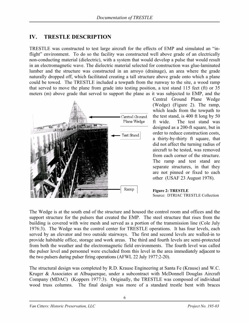
The most significant types of EMP environments are those associated with an exoatmospheric nuclear detonation, or high-altitude nuclear explosion (HEMP), which exists outside the source region in the air and on the earth (Figure 4). The environment created by HEMP would affect systems above the atmosphere, in the atmosphere but outside the source region, and on the surface of the earth. There are two classes of simulators for EMP that occur outside of the source region:
a) Those that simulate an approximate freespace plane wave on the system; b) Those that simulate such a plane wave plus the reflection from the surface of the earth
(Baum 1978:38).
Documentation of TRESTLE
13
Van Citters: Historic Preservation, LLC Project No. 195-03
Figure 4: Geometry of a high altitude burst
Source: Drawn by Karen Van Citters from Baum 1978 Simulator Design at AFWL
Simulator Construction and Figures of Merit A simulator should provide the electrical excitation for simulation without having the presence of the simulator significantly alter the response of the test system; i.e. the simulator itself should not affect the outcome of the tests. Because simulators simulate a specific environment and do not actually create that environment, there are performance limitations built into the system. For each simulator and test, there is a quantification of limitations so that there is a relationship between a system response in a simulator and a nominal EMP environment. This relationship is called the concept of “figures of merit.” The figures of merit “compare various features of the calculated and/or measured performance with some ideal (preferably simple) electromagnetic environment” (Baum 1978:37). Using the figures of merit approach to design allows scientists to exchange various performance components with constraints on money and time to achieve a balanced simulator design. The figures of merit approach was an important concept during the development of EMP simulators at Kirtland AFB. The AFWL and its design teams worked together using this method to produce simulators that created EMP environments with quantifiable limitations that were within budget and time constraints. AFWL and its contractors worked through several issues:
1) Determining the best type of EMP simulator for the system being tested 2) Configuring the major dimensions and other electromagnetic characteristics 3) Determining the desired characteristics of the appropriate electrical pulsers, photon
pulsers and/or generators (Baum 1978:50). The team required the following information to determine the best type of EMP simulator for the testing of a system:
Documentation of TRESTLE
14
Van Citters: Historic Preservation, LLC Project No. 195-03
1) The type of EMP to be simulated; 2) Where the system being tested would be located within the simulator; 3) Whether more than one type of EMP simulator should be used; 4) What the most efficient type of simulator was (balancing funding, time, with the
quality of the simulated environment); and 5) Whether additional simulators were necessary to accommodate long appendages
(Baum 1978:50). The following factors were important in configuring a simulator:
1) The dimensions of the system that was being tested; 2) The allowable “distortion of the system response” such as deviations of field
scattering and incorrect impedance; 3) Allowable field distortions and currents from less than ideal simulator characteristics; 4) Figures of merit; and 5) How to connect auxiliary EMP testing devices when appendages were part of the test
(Baum 1978:50). Pulser issues for EMP testing include:
1) The speed of the rising pulse; 2) The amplitude; 3) Pulse decay time; 4) Low-frequency content of the pulse; 5) The smoothness of the Fourier transform (a trigonometric series of terms) as a
function of the frequency over a frequency range; 6) What the pulser source impedance should be, the level of power of the generator; and 7) The range of frequencies and mode the generator should operate in and whether the
test would benefit from more than one type of pulser (Baum 1978:50). All these factors were used to determine the non-ideal features of the simulator and test and to assign a set of figures of merit for a simulator with respect to a specific system or group of systems that was to be tested. Design of the EMP simulator and determining parameters for simulator tests of systems both used the process of figures of merit. During the Cold War, a number of EMP simulators were constructed at different areas around Kirtland AFB: AFWL Characterization Interim Low Level EMP Simulator (ACHILLES) (Figure 5), AFWL Terrestrial High-Altitude EMP Alert Mode Aircraft Simulator (ATHAMAS) (Figure 6), ATLAS and the AFWL RAND EMP Simulator (ARES) (Figure 7). The ACHILLES simulators were constructed south of the runway and included the Vertically Polarized Dipole (VPD-I) (ACHILLES I), Los Alamos Scientific Laboratory EMP Calibration Simulator (ALECS), Hardness Surveillance Illuminator (HIS) (ACHILLES III) and Ellipticus (ACHILLES IV). The ATHAMAS area was constructed to the east of the runway and included the Horizontally Polarized Dipole (HPD) (ATHAMAS I) and VPD-II (ATHAMAS II). ARES and ATLAS were constructed just to the south of the ATHAMAS site. During conceptual design, ATLAS became known as TRESTLE. Because the design team used the approach of figures of merit, the construction of the EMP simulators was a design-build relationship (before the

Documentation of TRESTLE
15
Van Citters: Historic Preservation, LLC Project No. 195-03
construction term design-build became common nomenclature in the construction industry). AFWL would provide a concept and budget to the contractor and the contractor would develop a design that best met the testing requirements within the given budget. There was a back and forth dialog to develop the design that had the best EMP test capabilities for the available funding (Dana 2002).
Figure 5: ACHILLES Simulators
Source: Air Force Research Laboratory Phillips Research Site Historical Information Office
Figure 6: ATHAMAS Simulators
Source: Air Force Research Laboratory Phillips Research Site Historical Information Office
Figure 7: ARES Simulator
Source: Source: Air Force Research Laboratory Phillips Research Site Historical Information Office

Documentation of TRESTLE
16
Van Citters: Historic Preservation, LLC Project No. 195-03
Types of EMP Simulators Systems that would be in the air or above the atmosphere when an EMP wave hit them, such as aircraft or missiles, are best tested with a free space plane (uniform) wave. This is because the time delay between the incident wave and the wave reflected from the earth can be very large, making the effect on those systems from the reflected wave less significant than the initial wave. Systems that would be on or near the earth when a wave hit them are best tested with devices that can approximate the reflected wave from the earth. Various types of simulators can produce this reflection (Baum 1978:38). There are many classes of EMP simulators, but the three major types are: Dipole, Hybrid, and Guided Wave (Table 1). Table 2: Types of EMP simulators
Source: Giles 2000 and Baum 1978a
Simulator Class
Pulse Characteristics
Best Results Testing Mode
Dipole
Radiates; low frequencies are limited; fields are predicted analytically.
Systems in ground-alert mode.
Hybrid
Produces a pulse waveform that simulates a plane wave together with reflection from the earth’s surface.
Ground-based system exposed to EMP from a high-altitude nuclear detonation.
Guided
Can convert pulse power into uniform energy fields. Produces single plane wave for in-flight systems.
Aircraft or missiles in simulated in-flight configurations.
Dipole EMP simulators are a radiating class of devices. In dipoles, the simulator is located far from the system being tested in comparison to the size of the dipole structure. An electric dipole is a system in which a short distance separates two equal and opposite electrically charged poles; a common type of dipole simulator is a radiating EMP simulator (RES). RES is a large electric dipole that is a long thin rotationally symmetric body tapering along the length. RES included impedance loading, or opposition to the flow of electrical current created with resistors, to dampen oscillations that may have occurred when an electrical charge was applied. EMP simulators are resistively loaded to shape the radiated pulse and prevent large notches in the frequency spectrum (Giles 2000:13). RES I was developed in the early 1970s to test large
ground-based facilities, including Minuteman silos, and had mobility, because it hung from a helicopter (Figure 8). Although designed to test ground-based facilities, the RES-I also tested the U.S. Navy’s EC-130Q (which was referred to as the “Take Charge and Move Out” or TACAMO) in flight.
Figure 8: RES-I in flight
Source: Air Force Research Laboratory Phillips Research Site Historical Information Office Another type of dipole simulator is a cone that is
Documentation of TRESTLE
17
Van Citters: Historic Preservation, LLC Project No. 195-03
resistively loaded and mounted on a ground plane. The ACHILLES I (VPD-I) is this type of dipole and was constructed to test aircraft in the ground-alert mode, or the mode where a reflected wave from the earth would affect the aircraft (Baum 1978:38; Giles 2000:13). The most distinctive dipole constructed during the Cold War was the EMPRESS II, which was modeled on the ACHILLES II (VPD II) at Kirtland AFB and located on a barge that traveled to deep water to test large naval vessels. The EMPRESS II was demolished post-Cold War. Appendix A shows the known existing dipole simulators. Hybrid simulators combine a variety of features to simulate plane waves and their ground reflection. Hybrids provide the “best available approximation to the environment that would be experienced by a ground-based system exposed to an EMP from a high-altitude nuclear detonation” (Giles 2000:14). In static simulators, the placement of the test system is very close to or within the structure of the EMP simulator. In these simulators, the incident fields produced are “uniform in the vicinity of the system” (Baum 1978:39). The frequencies in such a simulator are small and the corresponding wavelengths are large, compared to the structure of the simulator, so that “quasi static form of the fields is applicable” (Baum 1978:39). When testing “very small systems or penetrations (small antennas and apertures) on highly conductive surfaces of larger systems” (Baum 1978:39) this type of simulator is used. Hybrid simulators have three basic characteristics:
1) The early-time (high-frequency) portion of the waveform reaching the system is radiated from a relatively small source region compared to the major simulator dimensions.
2) The low-frequency portions of the waveform are associated with currents and charges distributed over the major dimensions of the simulator structure. This structure either surrounds the system or is very close to it.
3) The structure is sparse so that most of the high-frequency energy radiates out of the simulator without reflecting off the simulator structure. The structure is also impedance loaded to further reduce unwanted reflections in the simulator (Baum 1978:39).
There are two hybrid simulators remaining in the U.S.: the HPD at Kirtland AFB and a Navy facility in Maryland. Appendix B shows the locations of known hybrid simulators throughout the world. Guided or bounded wave simulators, the most common type of simulator, and the type that was used for TRESTLE, produce an EMP environment that is appropriate to that outside the source region and are primarily used for testing missiles and aircraft in simulated in-flight configurations. Guided wave simulators have been used to test ground vehicles, but those tests are not considered “high-fidelity simulation” because they do not provide for the ground reflection that is required to assess EMP coupling characteristics of systems on the surface of the earth (Giles 2000:7). These simulators use a wave guiding structure (typically metal plates driven by high voltage generators) that is two-dimensional: described by two orthogonal coordinates to propagate a wave to a third orthogonal coordinate. These wave-guiding structures have the ability to control the field distribution for the “frequencies of interest from wavelengths

Documentation of TRESTLE
18
Van Citters: Historic Preservation, LLC Project No. 195-03
small to large compared to cross-section dimensions” (Baum 1978:41). Appendix C shows the locations of known guided wave simulators. ACHILLES I (Figure 9) at Kirtland AFB was one of the first EMP simulators built, but during the Cold War, many were constructed for the U.S. Army, Navy and Air Force. In addition, the U.S., including the AFWL and EG&G, aided other countries in developing and constructing their own EMP simulators. The U.S. has aided in the development of simulators in Canada, France, Germany, Israel, Italy, the Netherlands, Sweden, Switzerland, the United Kingdom, and post Cold War in China, the Ukraine, and Russia. The International Electrotechnical Commission
(IEC) was the primary catalyst for the post Cold War work. Since 1999, the fifteen participating IEC member nations (Austria, Czech Republic, Finland, France, Germany, Italy, Japan, Mexico, Romania, Russia, Spain, Sweden, Switzerland, United Kingdom and the U.S.) have been working on the applicability of using the EMP simulators for the testing of civil and commercial equipment. There are currently 39 known simulators in 13 countries, which the IEC documented as simulators that may be adapted for civil use (Giles 2000:iii). Appendix D shows these simulators.
Figure 9: ACHILLES I (VPD-I)
Source: Air Force Research Laboratory Phillips Research Site Historical Information Office
Simulator Construction Program at Kirtland AFB On 10 February 1971, an existing contract between the AFWL and EG&G Incorporated (EG&G) (Contract No. F29601-71-C-0018), which had begun in October of 1970, was amended to include EG&G furnishing the engineering support necessary to install EMP facilities for ALECS, Siege Development Facility (SDF), the Simulated EMP Ground Environment (SIEGE) facilities and RES-1 Mobile. On 4 August 1971 EMP project officials modified the contract with EG&G to include a “VPD facility” (Duffner et al. 1978:69). This is the facility that became known as ACHILLES I, or VPD-I and cost $378,000 to construct (USAF 1973:4). Later, when HPD was added to the Kirtland AFB EMP simulators, it was scheduled to cost 1.6 million dollars (USAF 1973:4). During 1971, as design and construction moved forward for the EMP testing facilities, AFWL issued a solicitation for 18 contractors to produce proposals to conduct tests to evaluate EMP interaction with military aircraft, the actual experiments that would take place in the simulators. Five companies responded and AFWL selected two to participate in the program: Boeing Company and the Autonetics Division of North American Rockwell. On September 16, 1971,
Documentation of TRESTLE
19
Van Citters: Historic Preservation, LLC Project No. 195-03
AFWL awarded a contract to Boeing Company (Contract Number F29601-72-C-0028) to test the following systems:
1) B-52; 2) EC-135; 3) Airborne Warning and Control System (AWACS); 4) E-4 (Boeing 747), Advanced Airborne National Command Post (AABNCP); 5) Short-range attack missile (SRAM); 6) B-52 electro-optical viewing system (EVS); 7) Rivet Ace–electronic countermeasure equipment aboard the B-52; and 8) Hound Dog I.
The contract with Autonetics Division of North American Rockwell (Contract Number F29601-72-C-0037) included testing for the following:
1) B-1; 2) SRAM, “on board” computer; 3) FB-111 inertial navigation system; and 4) Hound Dog II.
The charge for both companies was to research, develop, and experimentally test for EMP. The VPD-I, HPD, and RES-1 airborne simulator were to be made available for this work and EG&G staff were to provide support for tests conducted at the facilities (Dana 2002). Under the above testing contracts, it was envisioned that tests would also occur at a modified ALECS facility and a new simulator that was still in the design stage: TRESTLE (Duffner et al. 1972:163).
Requirement for “In-Flight” Simulator VPD-I was constructed to test the AABNCP and AFWL envisioned that HPD, once constructed, would also be used to test the aircraft, as well as the B-52 and EC-135 in ground alert mode, but these dipole simulators would not provide full data on EMP effects and could not simulate and in-flight mode. In the VPD and HPD simulators scientists had to contend with reflection of the EMP wave off the ground, which affected the accuracy of the results. This reflection could cancel the electric field of much of the incoming wave and the ground would image the gross electrical configuration of the aircraft. In HPD, this effect was profound, but in VPD, it was not as great because the waves were vertical, although the image effect did become a factor in test accuracy (USAF 1973:1; HQ USAF 1973:5; Defense Science Board 1975:9). In ARES and ALECS the reflection problem was avoided by adding a metal mesh at grade to serve as “conducting sheets” that would isolate the main portion of the electromagnetic wave from significance influence of the soil (Baum 1969:2). The only means of removing the ground plane reflection to overcome the effects of horizontal field cancellation and ground plane imagery to simulate an in-flight mode was to remove the influence of the ground from the aircraft (Defense Science Board 1975:9). By removing the ground, the aircraft could be tested virtually as though it were in flight (Figure 10). To create this environment at TRESTLE, the aircraft would be placed on a non-conducting platform

Documentation of TRESTLE
20
Van Citters: Historic Preservation, LLC Project No. 195-03
constructed above the ground and of a non-conducting and non-reflective material so that the simulated test would “see” it as air and use horizontal transmission lines supported high above
the ground (USAF 1973:1–2). In addition, with this configuration, the aircraft could be tested in its normal upright position with the incident electrical field parallel to the largest dimensions of the aircraft, the body or wings (Baum 1969:2). TRESTLE was intended to support the test program with such in-flight capabilities and provide an environment with considerably fewer testing limitations than VPD and HPD.
Figure 10: Conceptual View of Aircraft on Trestle-type simulator
Source: AFWL 24 August 1971
The in-flight characteristics that could not be tested in a simulator, because simulators were constructed on the ground, were the effects of “aerodynamic loading, vibration, cold soak, and reduced atmospheric pressure” (Defense Science Board 1975:10). To compensate the Defense Science Board (DSB) recommended comparing low-field strength tests within a flying aircraft to high-field strength tests at TRESTLE to examine these flight effects on electromagnetic coupling. Because aerodynamic loading, vibration, and cold soak can be evaluated linearly, the comparison would provide suitable extrapolated data. However, because the effects of reduced atmospheric pressure on the corona discharge from aircraft surfaces and the breakdown between conductors to the interior of the aircraft is non-linear, the comparison technique could not apply. In order to investigate the corona phenomena the DSB recommended that the Air Force consider experimental and analytical methods, rather than using low field strengths on an aircraft that was in flight or EMP simulation on the ground (Defense Science Board 1975:10–11).
TRESTLE Conceptual Design AFWL Design Development In April 1969, a member of the AFWL technical staff, Captain Carl Baum, documented the necessity for a large horizontally polarized transmission line to simulate the effect of free-space (in-flight) electromagnetic plane waves on large aircraft and summarized the problems associated with such a simulator in his “Sensor and Simulation Notes, Note 82”:
… for large transmission lines for simulating fields over large systems (missiles, aircraft, etc.) the cross-section dimensions can get rather large … In addition, supporting the system to be tested at such heights further increases the construction difficulty. If one also has to support a large high voltage pulser (or pulsers) the difficulty is further compounded (Baum 1969:9).
Documentation of TRESTLE
21
Van Citters: Historic Preservation, LLC Project No. 195-03
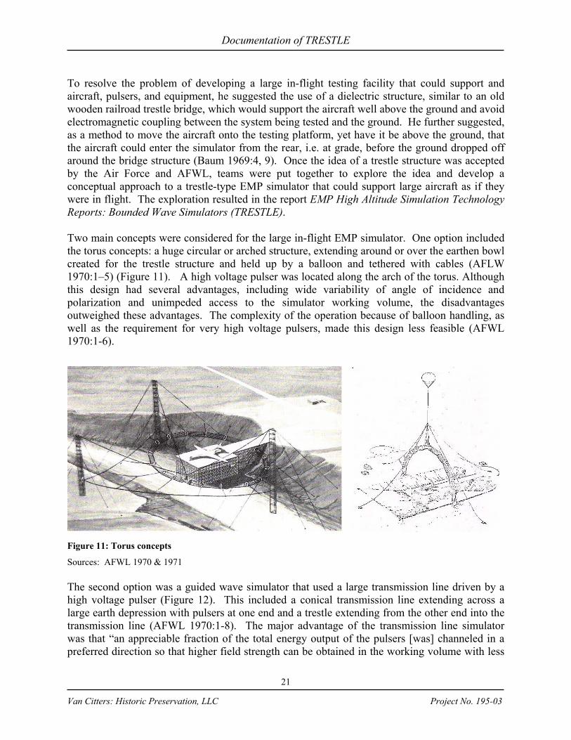
To resolve the problem of developing a large in-flight testing facility that could support and aircraft, pulsers, and equipment, he suggested the use of a dielectric structure, similar to an old wooden railroad trestle bridge, which would support the aircraft well above the ground and avoid electromagnetic coupling between the system being tested and the ground. He further suggested, as a method to move the aircraft onto the testing platform, yet have it be above the ground, that the aircraft could enter the simulator from the rear, i.e. at grade, before the ground dropped off around the bridge structure (Baum 1969:4, 9). Once the idea of a trestle structure was accepted by the Air Force and AFWL, teams were put together to explore the idea and develop a conceptual approach to a trestle-type EMP simulator that could support large aircraft as if they were in flight. The exploration resulted in the report EMP High Altitude Simulation Technology Reports: Bounded Wave Simulators (TRESTLE). Two main concepts were considered for the large in-flight EMP simulator. One option included the torus concepts: a huge circular or arched structure, extending around or over the earthen bowl created for the trestle structure and held up by a balloon and tethered with cables (AFLW 1970:1–5) (Figure 11). A high voltage pulser was located along the arch of the torus. Although this design had several advantages, including wide variability of angle of incidence and polarization and unimpeded access to the simulator working volume, the disadvantages outweighed these advantages. The complexity of the operation because of balloon handling, as well as the requirement for very high voltage pulsers, made this design less feasible (AFWL 1970:1-6).
Figure 11: Torus concepts
Sources: AFWL 1970 & 1971 The second option was a guided wave simulator that used a large transmission line driven by a high voltage pulser (Figure 12). This included a conical transmission line extending across a large earth depression with pulsers at one end and a trestle extending from the other end into the transmission line (AFWL 1970:1-8). The major advantage of the transmission line simulator was that “an appreciable fraction of the total energy output of the pulsers [was] channeled in a preferred direction so that higher field strength can be obtained in the working volume with less
Documentation of TRESTLE
22
Van Citters: Historic Preservation, LLC Project No. 195-03
energetic pulsers” (AFWL 1970:1-9). The required pulsers to operate such a system were thought to be available at the time; however, the system could not provide the versatility in polarization and propagation direction that the torus design could (AFWL 1970:1-9). Figure 12: Bounded wave simulator concept
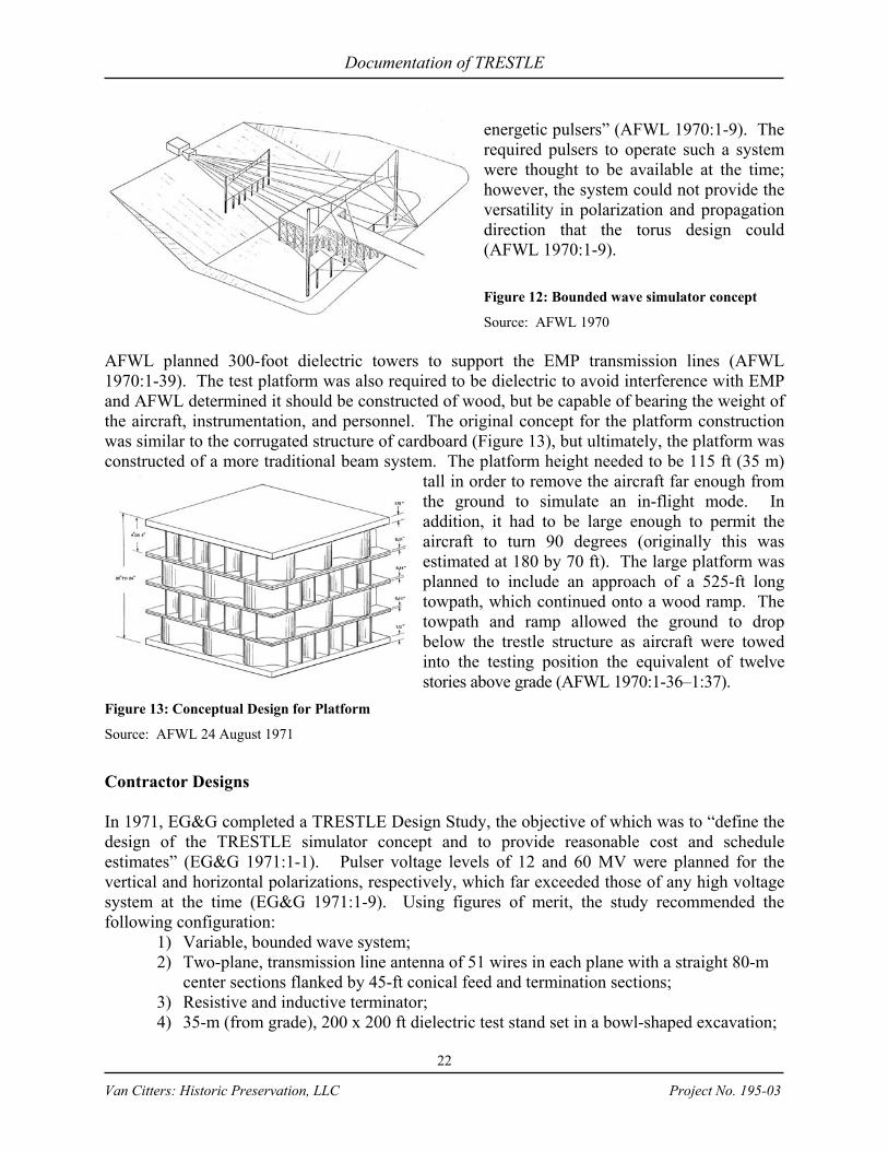
Source: AFWL 1970 AFWL planned 300-foot dielectric towers to support the EMP transmission lines (AFWL 1970:1-39). The test platform was also required to be dielectric to avoid interference with EMP and AFWL determined it should be constructed of wood, but be capable of bearing the weight of the aircraft, instrumentation, and personnel. The original concept for the platform construction was similar to the corrugated structure of cardboard (Figure 13), but ultimately, the platform was constructed of a more traditional beam system. The platform height needed to be 115 ft (35 m)
tall in order to remove the aircraft far enough from the ground to simulate an in-flight mode. In addition, it had to be large enough to permit the aircraft to turn 90 degrees (originally this was estimated at 180 by 70 ft). The large platform was planned to include an approach of a 525-ft long towpath, which continued onto a wood ramp. The towpath and ramp allowed the ground to drop below the trestle structure as aircraft were towed into the testing position the equivalent of twelve stories above grade (AFWL 1970:1-36–1:37).
Figure 13: Conceptual Design for Platform
Source: AFWL 24 August 1971
Contractor Designs In 1971, EG&G completed a TRESTLE Design Study, the objective of which was to “define the design of the TRESTLE simulator concept and to provide reasonable cost and schedule estimates” (EG&G 1971:1-1). Pulser voltage levels of 12 and 60 MV were planned for the vertical and horizontal polarizations, respectively, which far exceeded those of any high voltage system at the time (EG&G 1971:1-9). Using figures of merit, the study recommended the following configuration:
1) Variable, bounded wave system; 2) Two-plane, transmission line antenna of 51 wires in each plane with a straight 80-m
center sections flanked by 45-ft conical feed and termination sections; 3) Resistive and inductive terminator; 4) 35-m (from grade), 200 x 200 ft dielectric test stand set in a bowl-shaped excavation;
Documentation of TRESTLE
23
Van Citters: Historic Preservation, LLC Project No. 195-03
5) Command, control, and data monitoring center; and administrative and support facilities (EG&G 1971:2-1 & 2-2).
In September of 1971, the Air Force sought companies with the appropriate research and development (R&D) experience for the TRESTLE program to: “manage, integrate and fabricate high voltage pulse generators, large antenna structures, and large dielectric (such as wood) structures” (AFSWC 1971:1). The Air Force contracted with MDAC, Boeing, and General Dynamics to “define what such a simulator might look like” (Tate 25 Jan 81:3). None of the resulting proposals was selected, but ideas from the three contractor’s designs were studied by scientists at AFWL (Project 1209 1973:2). “The best features of each were incorporated into a new procurement package that was resubmitted with MDAC the eventual winner in Apr 1973” (Tate 25 Jan 81:3).
The Air Force Program for TRESTLE Construction From 1968 to 1971 EG&G and AFWL investigated in-flight EMP simulation and conducted feasibility studies. Once the Air Force considered a trestle EMP simulation facility viable, the project entered what was later referred to as “Phase O.” This phase consisted of pulser studies and the conceptual design competition between MDAC, Boeing, and General Dynamics (AFWL n.d. a). During this phase, Los Alamos Scientific Laboratory (LASL) was also approached to aid AFWL with general support in mechanical, structural and some theoretical areas, but the laboratory rejected the idea (Project 1209 1973:1).
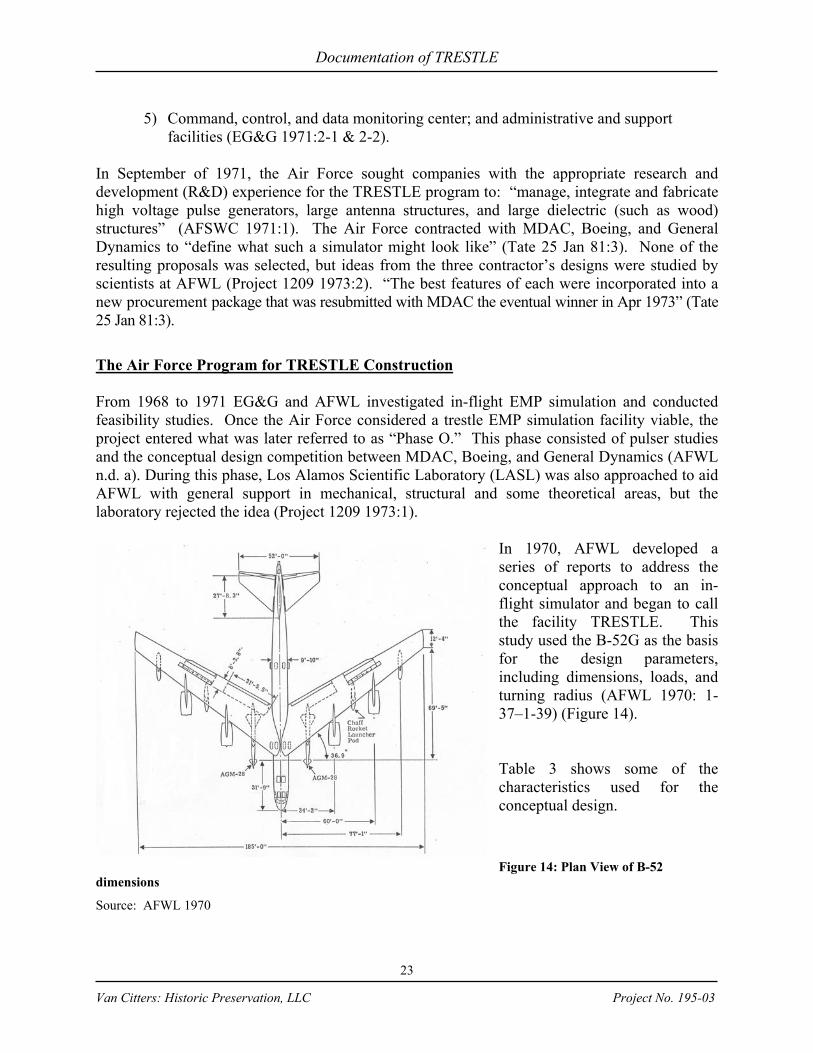
In 1970, AFWL developed a series of reports to address the conceptual approach to an in-flight simulator and began to call the facility TRESTLE. This study used the B-52G as the basis for the design parameters, including dimensions, loads, and turning radius (AFWL 1970: 1-37–1-39) (Figure 14). Table 3 shows some of the characteristics used for the conceptual design. Figure 14: Plan View of B-52
dimensions
Source: AFWL 1970
Documentation of TRESTLE
24
Van Citters: Historic Preservation, LLC Project No. 195-03
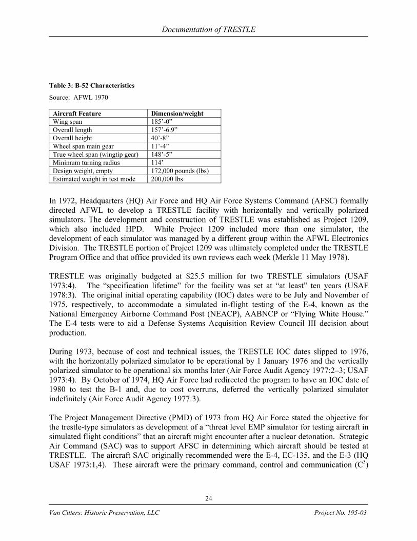
Table 3: B-52 Characteristics
Source: AFWL 1970
Aircraft Feature Dimension/weight Wing span 185’-0” Overall length 157’-6.9” Overall height 40’-8” Wheel span main gear 11’-4” True wheel span (wingtip gear) 148’-5” Minimum turning radius 114’ Design weight, empty 172,000 pounds (lbs) Estimated weight in test mode 200,000 lbs
In 1972, Headquarters (HQ) Air Force and HQ Air Force Systems Command (AFSC) formally directed AFWL to develop a TRESTLE facility with horizontally and vertically polarized simulators. The development and construction of TRESTLE was established as Project 1209, which also included HPD. While Project 1209 included more than one simulator, the development of each simulator was managed by a different group within the AFWL Electronics Division. The TRESTLE portion of Project 1209 was ultimately completed under the TRESTLE Program Office and that office provided its own reviews each week (Merkle 11 May 1978). TRESTLE was originally budgeted at $25.5 million for two TRESTLE simulators (USAF 1973:4). The “specification lifetime” for the facility was set at “at least” ten years (USAF 1978:3). The original initial operating capability (IOC) dates were to be July and November of 1975, respectively, to accommodate a simulated in-flight testing of the E-4, known as the National Emergency Airborne Command Post (NEACP), AABNCP or “Flying White House.” The E-4 tests were to aid a Defense Systems Acquisition Review Council III decision about production. During 1973, because of cost and technical issues, the TRESTLE IOC dates slipped to 1976, with the horizontally polarized simulator to be operational by 1 January 1976 and the vertically polarized simulator to be operational six months later (Air Force Audit Agency 1977:2–3; USAF 1973:4). By October of 1974, HQ Air Force had redirected the program to have an IOC date of 1980 to test the B-1 and, due to cost overruns, deferred the vertically polarized simulator indefinitely (Air Force Audit Agency 1977:3). The Project Management Directive (PMD) of 1973 from HQ Air Force stated the objective for the trestle-type simulators as development of a “threat level EMP simulator for testing aircraft in simulated flight conditions” that an aircraft might encounter after a nuclear detonation. Strategic Air Command (SAC) was to support AFSC in determining which aircraft should be tested at TRESTLE. The aircraft SAC originally recommended were the E-4, EC-135, and the E-3 (HQ USAF 1973:1,4). These aircraft were the primary command, control and communication (C3)
Documentation of TRESTLE
25
Van Citters: Historic Preservation, LLC Project No. 195-03
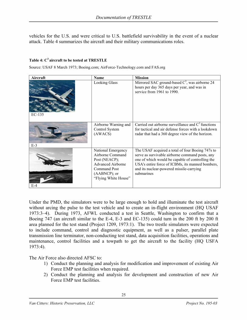
vehicles for the U.S. and were critical to U.S. battlefield survivability in the event of a nuclear attack. Table 4 summarizes the aircraft and their military communications roles. Table 4: C3 aircraft to be tested at TRESTLE
Source: USAF 8 March 1973; Boeing.com; AirForce-Technology.com and FAS.org
Aircraft Name Mission
EC-135
Looking Glass Mirrored SAC ground-based C3, was airborne 24 hours per day 365 days per year, and was in service from 1961 to 1990.
E-3
Airborne Warning and Control System (AWACS)
Carried out airborne surveillance and C3 functions for tactical and air defense forces with a lookdown radar that had a 360 degree view of the horizon.
E-4
National Emergency Airborne Command Post (NEACP); Advanced Airborne Command Post (AABNCP); or “Flying White House”
The USAF acquired a total of four Boeing 747s to serve as survivable airborne command posts, any one of which would be capable of controlling the USA's entire force of ICBMs, its manned bombers, and its nuclear-powered missile-carrying submarines
Under the PMD, the simulators were to be large enough to hold and illuminate the test aircraft without arcing the pulse to the test vehicle and to create an in-flight environment (HQ USAF 1973:3–4). During 1973, AFWL conducted a test in Seattle, Washington to confirm that a Boeing 747 (an aircraft similar to the E-4, E-3 and EC-135) could turn in the 200 ft by 200 ft area planned for the test stand (Project 1209, 1973:1). The two trestle simulators were expected to include command, control and diagnostic equipment, as well as a pulser, parallel plate transmission line terminator, non-conducting test stand, data acquisition facilities, operations and maintenance, control facilities and a towpath to get the aircraft to the facility (HQ USFA 1973:4). The Air Force also directed AFSC to:
1) Conduct the planning and analysis for modification and improvement of existing Air Force EMP test facilities when required.
2) Conduct the planning and analysis for development and construction of new Air Force EMP test facilities.
Documentation of TRESTLE
26
Van Citters: Historic Preservation, LLC Project No. 195-03
3) Develop, construct, modify and improve EMP test facilities as required and with an approved HQ USAF D&F.
4) Interact with other agencies developing and constructing EMP test facilities (HQ USAF 1973:2).
In addition to EMP, the HQ Air Force PMD stated that TRESTLE might be used to test aircraft vulnerability by modulations and electromagnetic energy across a frequency spectrum up to 17.0 gigahertz (GHz) to simulate other types of electromagnetic radiation including continuous wave and radar pulse. This was intended to be the worst-case electromagnetic environment that an aircraft might face during its lifetime (HQ USAF 1973:5). In October of 1973 Colonel John Portasik, Chief of AFWL Electronics Division, wrote a memo responding to the PMD request to develop electromagnetic radiation testing at TRESTLE. In the memo, he stated that it would be feasible if additional energy sources were obtained, but that more time was needed than allowed for in the PMD to define the testing scenario. In addition, he was concerned with how the radiation might interact with the surrounding environment (Portasik 1973:1). Because the TRESTLE pulsers ultimately had difficulty in obtaining the desired frequencies for the planned EMP tests, the 17.0 GHz levels for electromagnetic radiation were never obtained. After the original MDAC, Boeing, and General Dynamics proposals were evaluated and rejected, the project was resolicited. The new prime contractor proposals were resubmitted on 22 December 1972 and evaluated in the early part of 1973. The contract negotiations with the selected contractor began in March (Project 1209, 1973:4). The negotiations resulted in a cost plus incentive fee TRESTLE contract (F29601-73-C-0090) for $17.8 million, which was awarded in April of 1973 to MDAC in Huntington Beach, California. The primary subcontractors under the MDAC contract were:
2) Maxwell Laboratories, Inc. (MLI) for pulser design and construction; 3) Braddock, Dunn and McDonald (BDM) for electromagnetic analysis, timing and
control equipment; 4) W.C. Kruger & Associates for architectural and engineering design; 5) R.D. Krause Engineering Company for engineering design; and 6) Hunt Building Company for general construction (Jedlicka 1977:3).
The TRESTLE development program included military and civilian staff members, as well as consultants to support the engineering analysis for the design of TRESTLE and review of the work completed by MDAC and its design consultants. In 1974 Colonel Swan, Chief of AFWL Electronics Division, requested a sole source hire of Stadelmann Engineering, Inc., from Wisconsin, to aid AFWL with such design support. In his request, Colonel Swan described TRESTLE as “one of the most complex wood structures” constructed to-date and estimated the construction cost at $8 million (Swan 1974; Bracher 1974). There were a number of TRESTLE staff changes during 1974. After these changes, the primary group of military staff at the TRESTLE Program Office included many well-trained engineers with project experience on a number of strategic weapons systems including the Titan,

Documentation of TRESTLE
27
Van Citters: Historic Preservation, LLC Project No. 195-03
Minuteman, North American Aerospace Defense Command (NORAD), as well as structural, data processing, and nuclear engineering backgrounds. Table 5 shows primary staff, their educational backgrounds, and experience prior to working with the TRESTLE Program Office. Table 5: TRESTLE Staff
Source: DTRIAC Trestle Collection, staff reports
Name Education Experience prior to TRESTLE Lt. Colonel Cole BS–U.S. Naval Academy
MS – Astronautics, AFIT 5 years Holloman AFB, Project Officer Titan II and Chief Project Engineering Section, Test Track 5 years SAMSO, Chief Minuteman Guidance & Control Division
Lt. Colonel Merkle
BCE – Cornell MSCE, Structures – Cornell PhD, Structural Mechanics, MIT
4 years protective construction, shock isolation, soil-structure interaction 6 years U.S. Air Force Academy, associate professor of civil engineering, structures, soil, foundations, water supply
Major Richers BS – U.S. Air Force Academy Graduate work in weapons systems – AFIT
14 years working with strategic weapons systems SAC Wing Chief of Safety PE Safety
Major Jedlicka BS – Astronomy, Case Institute NORAD Project Officer Project Officer, large antenna array construction in Norway AFWL PR Project Officer
Captain Slater BS, Mechanical Engineering, Arizona State
3 years AFAL, Fusing Project Officer
Captain Fostiak BSEE, Chicago Technical College 5 years ESD, Tactical Data Processing Project Officer. William Shover BSEE – UNM
MSEE, Systems Analysis, UNM 4 years arming and fusing (coop)
John Ungvarsky BSME – Penn State Graduate work in mechanical engineering at NYU, UCONN, UNM and UCLA
3 year combustion engineering nuclear products division, mechanical design of reactor components 8 months American Car & Foundry, design of gas cooled nuclear reactor components 2 years AFWL, Mechanical Support Equipment Branch, Development directorate 4 years AFWL Nuclear Safety Division/Nuclear power Branch 8 years TRESS, underground nuclear testing at NTS
TRESTLE Contracting and Program Realignment Shortly after the MDAC contract award, during the period from 1973–1975, the TRESTLE component of Project 1209 experienced significant cost, schedule, and management problems. Because of structural design problems, underestimating the amount of lumber, and inflation, the cost increased from the original estimate of $25.5 million to $39.4 million by April of 1974. Within months, by October of 1974, the cost estimate to complete the simulator rose to $59.3 million (Air Force Audit Agency 1977:3; TRESTLE Program Office 21 July 1978a). TRESTLE cost growth during this period was affected by inflation, poor estimating, project contracting

Documentation of TRESTLE
28
Van Citters: Historic Preservation, LLC Project No. 195-03
methods, funding limitations, contract termination, and schedule extensions. Air Staff and HQ AFSC helped to redirect and assist the TRESTLE program to get the project back on track (Air Force Audit Agency 1977:2). During 1973 and 1974, TRESTLE development was in the “TRESTLE Section” of the Simulator Development Branch under the Electronics Division of AFWL. During the period that TRESTLE was in the Electronics Division, the TRESTLE Program Manager did not have direct access to the AFWL Commander and there was not a full time configuration contract manager on the team. In addition, the TRESTLE Funds Manager did not report to the Program Manager (PMAT 1974:5). This organizational configuration may have led to some of the information, cost, and contract control issues that weighed down the development of TRESTLE. The April 1973 contract that the Simulator Development Branch awarded to MDAC was a “cost plus incentive fee” contract. It included the cost of the project and an incentive or bonus for MDAC to complete the project within budget and ahead of schedule. By September, five months after the contract was let, MDAC alerted the Simulator Development Branch about a project cost overrun. In early 1974, MDAC developed a formal Estimate at Completion (EAC) for the TRESTLE, which documented the significant cost overrun (AFWL n.d. b). MDAC informed the Simulator Development Branch that the TRESTLE costs were going to exceed the Contract Target Cost due to inflation, the energy crisis, and escalating labor rates (Futch and Swan 26 Mar 74). As a result, in March 1974, MDAC was directed to stop work on the vertical simulator while the Air Force determined in what direction the project should continue. The goal of the stop work order was to ensure that MDAC would not incur more liabilities than the Air Force could cover (Futch and Swan 6 March 1974). Shortly thereafter, AFWL required that MDAC develop a new EAC of the horizontal simulator only, while AFWL developed new “high confidence” government estimates (Sweeney 30 June 1974). The unpredictable economic escalation, methods for calculating the original estimates and the change in design originally contributed to the cost growth, but were also exacerbated by the internal review process for the project and contracting issues (PMAT 1974:3). During the reassessment of MDACs contract, the Air Force stated, “… it is not inconceivable that the cost [of the original $18 million contract] may eventually rise beyond $20 million” (Castillo 8 April 1974:3). The original project estimates for TRESTLE were completed in rough order of magnitude (ROM). The ROM estimates included inflation rates of 18% and 41% per year, for labor and material, respectively. The labor inflation rate was compounded annually, but the material was not. In addition, when the original wood estimates were prepared, neither MDAC nor AFWL realized the magnitude of difference between net board feet and gross board feet. AFWL was not aware that 100 % net board feet is equivalent to 60% gross board feet and that the original MDAC estimate used net board feet. This built a 40% error into the original wood estimate. That error coupled with the fact that wood costs grew greatly in the year after the estimate was completed and the method used to apply inflation to materials, meant that the TRESTLE program wood costs were substantially underestimated (PMAT 1974:4) (Table 6).
Table 6: Inflation effects on TRESTLE
Source: AFWL n.d. c
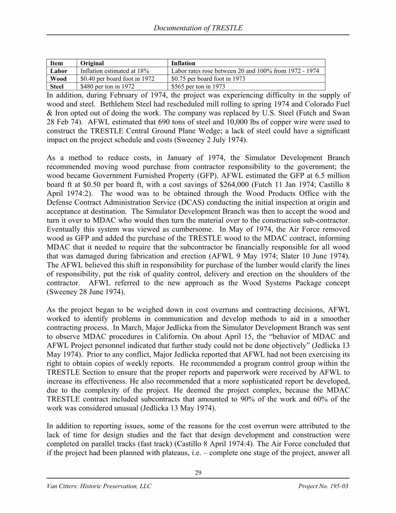
Documentation of TRESTLE
29
Van Citters: Historic Preservation, LLC Project No. 195-03
Item Original Inflation Labor Inflation estimated at 18% Labor rates rose between 20 and 100% from 1972 - 1974 Wood $0.40 per board foot in 1972 $0.75 per board foot in 1973 Steel $480 per ton in 1972 $565 per ton in 1973
In addition, during February of 1974, the project was experiencing difficulty in the supply of wood and steel. Bethlehem Steel had rescheduled mill rolling to spring 1974 and Colorado Fuel & Iron opted out of doing the work. The company was replaced by U.S. Steel (Futch and Swan 28 Feb 74). AFWL estimated that 690 tons of steel and 10,000 lbs of copper wire were used to construct the TRESTLE Central Ground Plane Wedge; a lack of steel could have a significant impact on the project schedule and costs (Sweeney 2 July 1974). As a method to reduce costs, in January of 1974, the Simulator Development Branch recommended moving wood purchase from contractor responsibility to the government; the wood became Government Furnished Property (GFP). AFWL estimated the GFP at 6.5 million board ft at $0.50 per board ft, with a cost savings of $264,000 (Futch 11 Jan 1974; Castillo 8 April 1974:2). The wood was to be obtained through the Wood Products Office with the Defense Contract Administration Service (DCAS) conducting the initial inspection at origin and acceptance at destination. The Simulator Development Branch was then to accept the wood and turn it over to MDAC who would then turn the material over to the construction sub-contractor. Eventually this system was viewed as cumbersome. In May of 1974, the Air Force removed wood as GFP and added the purchase of the TRESTLE wood to the MDAC contract, informing MDAC that it needed to require that the subcontractor be financially responsible for all wood that was damaged during fabrication and erection (AFWL 9 May 1974; Slater 10 June 1974). The AFWL believed this shift in responsibility for purchase of the lumber would clarify the lines of responsibility, put the risk of quality control, delivery and erection on the shoulders of the contractor. AFWL referred to the new approach as the Wood Systems Package concept (Sweeney 28 June 1974). As the project began to be weighed down in cost overruns and contracting decisions, AFWL worked to identify problems in communication and develop methods to aid in a smoother contracting process. In March, Major Jedlicka from the Simulator Development Branch was sent to observe MDAC procedures in California. On about April 15, the “behavior of MDAC and AFWL Project personnel indicated that further study could not be done objectively” (Jedlicka 13 May 1974). Prior to any conflict, Major Jedlicka reported that AFWL had not been exercising its right to obtain copies of weekly reports. He recommended a program control group within the TRESTLE Section to ensure that the proper reports and paperwork were received by AFWL to increase its effectiveness. He also recommended that a more sophisticated report be developed, due to the complexity of the project. He deemed the project complex, because the MDAC TRESTLE contract included subcontracts that amounted to 90% of the work and 60% of the work was considered unusual (Jedlicka 13 May 1974). In addition to reporting issues, some of the reasons for the cost overrun were attributed to the lack of time for design studies and the fact that design development and construction were completed on parallel tracks (fast track) (Castillo 8 April 1974:4). The Air Force concluded that if the project had been planned with plateaus, i.e. – complete one stage of the project, answer all
Documentation of TRESTLE
30
Van Citters: Historic Preservation, LLC Project No. 195-03
the questions and then move to another, it would have progressed much more smoothly and been able to follow a budget (Castillo 8 April 1974:4). In April 1974, Phillip Castillo, the Acting Chief of the Simulator Development Branch, presented four budget options to complete TRESTLE facility.
1) Eliminate the vertical simulator and provide vertical polarization testing in VPD and through extrapolation.
2) Cancel the program. Castillo concluded this was not really an option, because without TRESTLE the Air Force could not test threat-level EMP on the fleet of aircraft.
3) Request additional funding to construct both the vertical and horizontal simulators. He summarized that with the fast track management methods, this was a very risky option.
4) Alter the program philosophy to finish each design stage in succession. He envisioned that the information that had been collected would be used to refine the TRESTLE development and that the current MDAC contract would be terminated and a construction contractor would be brought on to complete the facility. Concurrently, instrumentation and O&M [Operations & Maintenance] could be developed (Castillo 8 April 1974:5-7).
Castillo calculated that terminating the MDAC contract would cost $11 million, but that if the reorganization were done well, the overall cost to the program would be “insignificant” (Castillo 8 April 1974:7). In May 1974, the Air Force developed three program options to put the TRESTLE project back on track:
1) Option I (Minimum cost program): Continue program at minimum cost to meet AABNCP schedule and build both the horizontal and vertical simulators.
2) Option II (Avoid FY [fiscal year] 75 Congressional reprogramming action): Develop costs and schedules to avoid reprogramming and still complete the horizontal and vertical simulator to meet AABNCP schedule.
3) Option III (Defer vertical simulator): Develop costs and schedule required to avoid Congressional reprogramming action and defer vertical simulator to meet only the B-1 commitment, and keep the horizontal simulator on schedule for AABNCP (AFWL 30 June 1974:1; Larson 28 May 1974).
These options were estimated to cost $58.985, $65.373, and $70.150 million, respectively. Those costs did not include O&M or the facility users’ costs for configuration or instrumentation of aircraft, or ground handling equipment (AFWL 30 June 1974:1; Cole 31 July 1974). As such, a committee was formed to address such instrumentation issues. The resulting estimate to complete instrumentation was $3.5 million and the recommendation was made to include those costs in future requests for funding (Castillo 8 April 1974:4). In 1974, the AFSC TRESTLE Cost and Procurement Assistance Committee determined that the realigned project should be divided into three phases:

Documentation of TRESTLE
31
Van Citters: Historic Preservation, LLC Project No. 195-03
1) Phase I: Cost evaluation of MDAC proposals for the three program options. In this phase the committee would attempt to ensure that the methods used to determine costs were valid and realistic, given the information available to MDAC and that management and configuration control systems were adequate to ensure the proper program tracking.
2) Phase II: Selection of the desired option and contracting that option. This included defining the contract reporting requirements, reviewing the existing contract and determining what additional data should be reported to permit a tight contract management.
3) Phase III: Contract renegotiation. Based on the selection of one of the three program options, the existing MDAC contract was to be modified. The contract revision would include clauses that would permit tight contract management (Larson 29 May 1974:1).
At an April 1974 meeting held in Colonel Cunningham’s office, MDAC presented their estimate at completion for TRESTLE as $27,700,000, although the original negotiated figure was $18,490,000, not including the incentive fee. The new estimate did include TRESTLE fabrication by Hunt Building Corporation. A test stand/ramp quote from a company called Koppers for a sum of $11,745,000 was presented, which included fabrication and erection, and their subcontractor cost of $4,915,000. The wood was priced at $0.68 per board ft with an estimated 10,000,000 board ft; the original GFP estimate was 6,500,000 board ft at $0.50 per ft (Castillo 8 April 1974:1-2). The new cost estimates were indicative of some of the issues that were arising in the MDAC contract in general. MDAC entered into contracts with subcontractors based on a ROM. MDAC stated that MDAC was the only entity that could make reasonable cost ROMs for the TRESTLE project and believed that its cost estimates for the redesign of the horizontal simulator would be more accurate because the MDAC design was almost complete. In addition, the MDAC Program Manager stated that he believed MDACs estimates were valid within a range of 10% accuracy. The Air Force did not believe that that was the case and once the Koppers test stand/ramp bid was received, the MDAC estimate was proved inaccurate (PMAT 1974:4). While MDAC expected several bids on the redesign for the construction of the simulator, only the Koppers test stand/ramp bid was received for the wood purchase, fabrication, and erection, and that bid was 40% over the MDAC ROM for Option I. Once the Air Force evaluated the Koppers bid, it was determined that the bid was $6 million over the ROM estimate, which confirmed the level of uncertainty in the MDAC cost estimate process (PMAT 1974:7). This uncertainty was not only built into MDACs ROM estimates, but also their contracting process. If something was considered “low risk,” a firm fixed price contract was let (PMAT 1974:3). When MDAC issued the request for proposal (RFP) for construction of the TRESTLE wooden structures, it did not include the specifications for assembly and erection (Sweeney 11 June 1974). This resulted in the Koppers bid being accepted before the TRESTLE design was completed and approved by the Simulator Development Branch; structural analysis had not been completed; erection procedures had not been established; and the vertical design had not begun

Documentation of TRESTLE
32
Van Citters: Historic Preservation, LLC Project No. 195-03
(PMAT 1974:7). This resulted in the Air Force requesting MDAC submit such specifications prior to award of a contract for the construction of the wood structures (Sweeney 11 June 1974). In addition to the design and contracting issues, in June of 1974, the Air Force began to question whether MDAC would provide enough on-site supervision of the construction of TRESTLE (Sweeney 11 June 1974). Concurrently, Captain Goetz recommended that an on-site, warranted Contracting Officer (CO) be included in management of the TRESTLE contract, because the R&D nature of the contract with MDAC. He requested a site staff that included a Civil Engineering Officer with a structural background, a Mechanical Engineer, an Electrical Engineer and a military Site Development Technician. If a CO was not available for work at TRESTLE, he recommended that this field technical staff be empowered to issue stop work orders and work out agreements for field changes (Goetz 4 Jun 1974). In addition, to expedite design for TRESTLE the Air Force assembled a task force consisting of AFWL, MDAC, and BDM to develop computer methods that would provide a complete analysis of the wood structure for “all conditions of loading” (Sweeney 26 July 1974). Changes to the Trestle program operations were made in a June 1974 memo to General Hudson:
1) Program manager was to report directly to AFWL Commander. 2) Recommending Lt. Colonel Donald C. Cole to serve as program manager (he had
previously served as the Chief of the Guidance Control Division in the Minuteman program).
3) Adding personnel as Configuration Management Officer and Program Control Officer.
4) A formal weekly review of the program by the AFWL Commander (name illegible, 27 June 1974).
The above changes required AFWL to submit for reorganization (Gomez 9 Aug 1974). This ultimately led to the establishment of the TRESTLE Program Office (Figure 15). In July 1974, Lt. Colonel Donald Cole was assigned as the new TRESTLE Program Manager (Cole 31 July 1974). In August, Lt. Colonel Cole assigned Captain Goetz to serve as the AFWL Resident Field Engineer for all government monitoring of the contractor’s on-site activities. Once design was complete, then Captain Slater would also relocate to the construction site to serve as the Construction Manager (Cole 6 August 1974). In August, Captain Fostiak, on behalf of Lt. Colonel Cole, requested that the CO require MDAC to properly process design changes. MDAC had changed the foundations from spread footings to caissons, without providing new design information to AFWL (Fostiak 21 August 1974a). AFWL considered this type of change to be substantial and was requesting that they be allowed to review such changes prior to construction, as was outlined in the Configuration Management Plan. To alleviate the issue he requested that MDAC supply past design changes and the affected construction drawings. MDAC resisted because they believed that providing AFWL with this review would result in “an interfering and meddling situation in their internal affairs” (Fostiak 21 August 1974b).

Documentation of TRESTLE
33
Van Citters: Historic Preservation, LLC Project No. 195-03
Figure 15: 1974 Organization Chart
Source: DTRIAC Trestle Collection, staff reports Lt. Colonel Cole did implement a new project process to include more control over engineering change procedures (ECP), to keep MDAC from making major design changes without prior knowledge of AFWL personnel (Cole 18 August 1974). In addition to ECPs, MDAC and its subcontractors also used a form called a “T-ROD” to serve as a written conversation record, to record a meeting or action item, or to serve as a transmittal for technical data. The AFWL requested approval of T-RODS to ensure that the statements in them were correct, because earlier T-RODS had included information that the AFWL considered misleading or incorrectly attributed to the TRESTLE Program Office (Cole 28 August 1974). AFWL also hoped that by reviewing T-RODs and ECPs that the construction process would progress more smoothly. As the project continued into September of 1974, AFWL and MDAC had many meetings about the Configuration Management Plan and engineering changes. MDAC gave a presentation on how trustworthy and responsible they were; the conclusion of the AFWL was that the meeting “settled absolutely nothing.” MDAC did release a new Configuration Management Plan, but AFWL believed that “the contractor does not intend to perform as written…they have no intention of releasing changes to us simultaneously with implementation on anything that could be the least bit controversial” (Thompson 27 Sep 1974). This is indicative of the deteriorating relationship between MDAC and AFWL, as well as the AFWL loss of confidence in MDACs capability to follow contract process and adequately complete the project. This lack of confidence and the budgetary issues led to the eventual termination of the MDAC contract. The FY 1975 budget for TRESTLE was $8.3 million, but the projected cost for the year was $12.2 million. On 16 August 1974, AFSC at Andrews AFB directed AFWL to enter into contract negotiations to develop a new program that would work within the $8.3 million budget. At the time, AFSC believed this would include eventual completion of the vertical facility design, but discontinuing all construction at that facility until further notice (Cole 31 July 1974; AFSC 16 August 1974). By August 23, AFSC directed AFWL to delete the vertical

Documentation of TRESTLE
34
Van Citters: Historic Preservation, LLC Project No. 195-03
facility from the program, project earliest possible IOC for the horizontal simulator, and provide detailed cost information on how the horizontal facility would be completed within budget (AFSC 23 August 1974). On 6 September 1974, the Air Force directed MDAC to develop a proposal to phase down their efforts to meet the available funding. MDAC was to complete the Wedge, horizontal simulator design, utilities, roads, and pulser development, but was directed to stop work on the test stand and ramp, transmission line, pulser support structure, and the terminator (Cole 10 Sep 1974; Steplowski 1975). On 28 January 1975 the MDAC contract was partially terminated, deleting the final checkout and “stop work” items, except the pulser support structure. MDAC was unable to find a responsive subcontractor to complete the pulser support structures (the subcontractors stated the size of the job and complexity were the reason they would not bid on the project), so on 18 March 1975 the AFWL also terminated the MDAC contract for the pulser support structures (AFWL 1 April 1975). In May of 1975, an Inspector General team identified program management deficiencies and as a result, another AFSC Program Management Assistance Team (PMAT) was sent to the site (an earlier team had been sent in 1974). The PMAT included multidisciplinary experienced personnel who were on-site for three months to assist the TRESTLE Program Office in resolving management issues (Air Force Audit Agency 1977:3–4). When the 1975 PMAT arrived at the TRESTLE, it was briefed that the project was funded in its entirety as an R&D effort. No funds were appropriated through the Military Construction Program, so PMAT recommendations were made to follow R&D procedures rather than civil engineering and construction procedures (Program Management Assistance Team 1975:1). However, because the project had a substantial construction component, the PMAT provided some recommendations to ensure construction was followed more closely. Prior to the PMAT evaluation and establishment of the TRESTLE Program Office, the Simulator Development Branch had requested more information about ECPs and T-RODs from MDAC. However, the R&D funding resulted in a lack of formality with regard to ECPs. As such, no system existed to determine the cost and schedule changes that would result from ECPs (PMAT 1974:6). ECPs are similar to the construction industry “change order.” Change orders are alterations or additions to the original design that are submitted by the contractor and reviewed by the architect or engineer for suitability to meet the requirements of the project. In some cases, change orders may have an affect on the cost of the project. On TRESTLE, if it had been funded as a construction project, change orders would have processed through Civil Engineering and Procurement. Because there were no procedures to accept change orders, and such procedures are required in order to control construction methods and costs, PMAT recommended a procedure for ECPs through development of Configuration Management (PMAT 1975:2). In addition, the project lacked critical schedule dates and procedures to review designs by the agencies involved in the project, so preliminary design, critical design, and RFP packages that were being developed by MDAC were not being reviewed by TRESTLE staff, Kirtland AFB Base Civil Engineering, and AFSC. The PMAT recommended that the Chief Engineer develop a progress chart, that a review/comment procedure be developed, and that the Construction

Documentation of TRESTLE
35
Van Citters: Historic Preservation, LLC Project No. 195-03
Surveillance Engineer be assigned the responsibility to ensure that up-to-date approved drawings were used for construction (PMAT 1975:3–4). Once the program was realigned, the cost of TRESTLE began to be controlled. Some of the changes to the program included:
1) Timely quarterly R&D management report; 2) A document to plan and redirect the program; 3) Clear internal procedures with well-defined organizational duties; 4) Financial controls to monitor the contractor; 5) Co-location of contractor and the TRESTLE Program Office (TP) at TRESTLE site; 6) Configuration management to control the processing of ECPs; and 7) Timely design reviews and monitoring architectural engineering through daily
evaluation reports (Air Force Audit Agency 1977:4–5). As the TRESTLE program was becoming more controlled, the Air Force and DSB were looking more closely at an IOC and what types of aircraft should be tested. The AABNCP was originally planned for testing in only the VPD and HPD simulators, but the DSB recommended that “complete operational” versions of the aircraft with the “on-board digital computing system” be tested in TRESTLE as soon as the aircraft was available (Defense Science Board 1975:12). The board also recommended that the TRESTLE be used to test the effects of aging, maintenance, and modifications to the B-1 and AABNCP. The board stated that the Air Force had other aircraft that should be tested and that the lack of plans for testing should not be seen as a result of TRESTLE’s limitations, but rather an indicator of a need for more long-range planning for EMP survivability testing (Defense Science Board 1975:12). While the vertical facility had been eliminated from the program in August of 1974, there was an open question as to whether it was required to fully test the AABNCP. In the fall of 1975 the Deputy Director, Strategic and Space Systems requested that the Systems Vulnerability Task Force of the DSB address two major questions:
1) Should TRESTLE be accelerated to accommodate early testing of the AABNCP; and
2) Could the horizontal TRESTLE adequately provide the necessary testing, or was the vertical simulator also required (Defense Science Board 1975:1).
As a result, the DSB stated that it was important to test the AABNCP, but because they did not know the delivery date for the aircraft, could not answer whether the construction at TRESTLE should be accelerated. They recommended that ideally the vertical facility would be constructed to provide a full testing of aircraft, but if it could not be constructed to meet the AABNCP, that the VPD should be upgraded to provide the best information. While the DSB believed that the VPD could provide some information, they stated that the data would more accurately resemble an on-ground threat level environment, rather than the in-flight characteristics required. The Systems Vulnerability Task Force determined that testing in “threat-level fields” was required in order to achieve a high order of confidence in aircraft EMP survivability and that the only viable option to obtain a high quality simulation was to isolate the aircraft from the ground by placing it on a platform (Defense Science Board 1975:1). As such, they recommended that TRESTLE was

Documentation of TRESTLE
36
Van Citters: Historic Preservation, LLC Project No. 195-03
a necessary “ingredient in any plan to demonstrate EMP survivability of aircraft which balances reasonable risk and cost” (Batzel 7 November 1975). In November of 1975, the AFSC notified AFWL that the AABNCP would be available for EMP testing by May of 1979, which required an accelerated program at TRESTLE to develop an IOC date of 31 March 1979. To meet the accelerated schedule, AFWL requested additional procurement support to process and monitor procurement packages and contracts simultaneously, as well as authorization to combine the test stand construction with the ramp/pulser stands/terminator contract. If the accelerated schedule were followed, AFWL was concerned that there would be insufficient time to validate the erection procedures that had been outlined in the procurement advertisement (Freyer 8 Dec 1975). In December of 1975, the TRESTLE Program Office moved to the TRESTLE simulator facility (Cole 11 Dec 1975). From there they were able to more closely monitor the site activities to oversee the final construction and closeout of the MDAC contract, as well as the construction of the items that were deleted from that contract and re-let to new contractors. This was also intended to aid in streamlining communication with MDAC. While construction of the horizontal simulator continued, the vertical simulator remained a project on hold (since its original elimination from the program in 1974). During 1975, the DSB had stated that the vertical simulator was required to develop a full in-flight testing of aircraft. This stance was updated in 1976 when the DSB stated that the horizontal TRESTLE was definitely required, but that the vertical facility may not be required. Horizontal polarization presents the worst-case EMP coupling, so the horizontal facility would ensure that the worst-case testing was completed (Castillo 8 April 1974:5). The new DSB recommendation was that the facility was not needed if upgrades to VPD could achieve an appropriate degree of simulation in time to meet the testing schedule for the AABNCP and B-1 aircraft (presumably this fed into the HQ Air Force decision to cancel the vertical facility) (Buchsbaum 1976) (Figure 16). While TRESTLE was the only way to achieve a high quality simulation, the DSB pointed out that neither the horizontal or vertical simulators, because of their limitations would constitute a “proof test.” As such, the DSB recommended that the System Program Office that was conducting the test should develop a comprehensive test program that would combine TRESTLE data with other analyses, empirical or from other simulators, to produce a more thorough overall assessment of system survivability (Defense Science Board 1975:2–3).
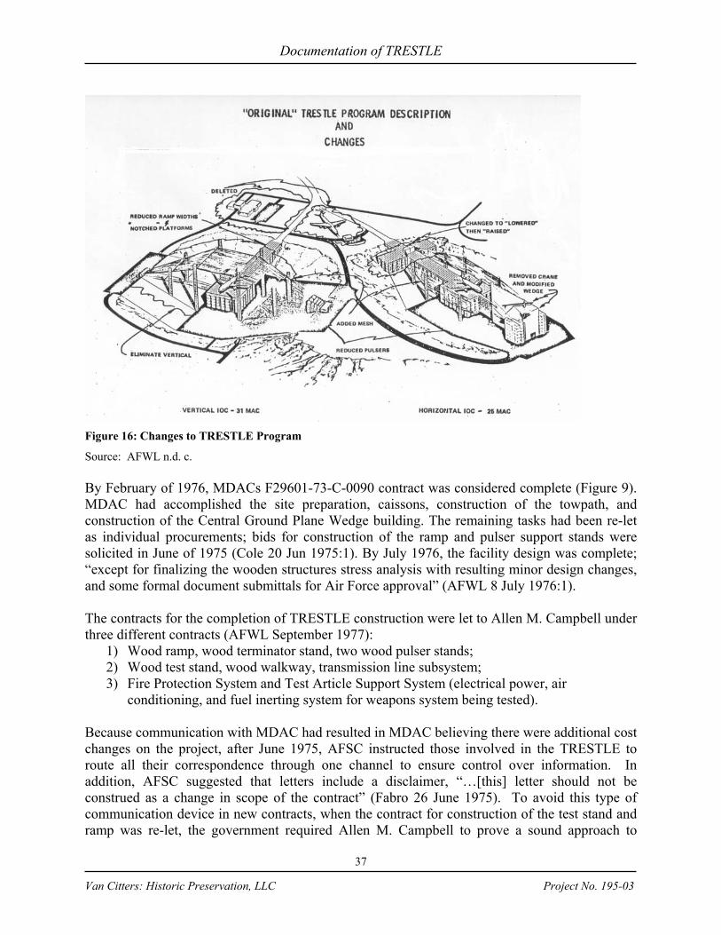
Documentation of TRESTLE
37
Van Citters: Historic Preservation, LLC Project No. 195-03
Figure 16: Changes to TRESTLE Program
Source: AFWL n.d. c. By February of 1976, MDACs F29601-73-C-0090 contract was considered complete (Figure 9). MDAC had accomplished the site preparation, caissons, construction of the towpath, and construction of the Central Ground Plane Wedge building. The remaining tasks had been re-let as individual procurements; bids for construction of the ramp and pulser support stands were solicited in June of 1975 (Cole 20 Jun 1975:1). By July 1976, the facility design was complete; “except for finalizing the wooden structures stress analysis with resulting minor design changes, and some formal document submittals for Air Force approval” (AFWL 8 July 1976:1). The contracts for the completion of TRESTLE construction were let to Allen M. Campbell under three different contracts (AFWL September 1977):
1) Wood ramp, wood terminator stand, two wood pulser stands; 2) Wood test stand, wood walkway, transmission line subsystem; 3) Fire Protection System and Test Article Support System (electrical power, air
conditioning, and fuel inerting system for weapons system being tested). Because communication with MDAC had resulted in MDAC believing there were additional cost changes on the project, after June 1975, AFSC instructed those involved in the TRESTLE to route all their correspondence through one channel to ensure control over information. In addition, AFSC suggested that letters include a disclaimer, “…[this] letter should not be construed as a change in scope of the contract” (Fabro 26 June 1975). To avoid this type of communication device in new contracts, when the contract for construction of the test stand and ramp was re-let, the government required Allen M. Campbell to prove a sound approach to

Documentation of TRESTLE
38
Van Citters: Historic Preservation, LLC Project No. 195-03
fabrication and erection of the structural members. The primary factors they reviewed included developing methods to:
1) Deal with the tolerance buildup that was a result of cumulative effects of manufacturing processes and member imperfections that may cause a member to not fit into place on-site.
2) Minimize the impact of member imperfections on alignment during erection. 3) Simultaneously align the place all the split rings in a multiple-connector group. 4) Work with long members to ensure that the handling stresses would not exceed their
allowable loads and determining erection stresses. 5) Ensure that material is available when needed for erection to avoid construction
delays. 6) Deal with the irregular ground slope and unusual height of the structures. 7) Provide a smooth assembly and erection sequence (AFWL n.d.c).
Although the above was required, during the initial Allen M. Campbell construction, the work was behind schedule due to flow of materials from the glue-laminated lumber manufacturer. In addition, the contractor had difficulty with certification and inspection of materials and completing their test reports (Fostiak and Thompson 16 Nov 1976). After a few months, Allen M. Campbell performance was much improved and only minor items were behind schedule. A TRESTLE Program Office analysis of the contract showed that Allen M. Campbell demonstrated outstanding engineering competence and that their personnel were good at solving technical problems to ensure quality work. In many cases, their work exceeded specifications and their staff was noted to have “a high level of professionalism and dedication” (Merkle 8 Dec 1976).
By November 1977 Allen M. Campbell Co. had completed 40% of the test stand; 52 of the 90 bents had been fabricated, assembled and erected (Figure 17). In addition, 90% of the transmission line for the Central Ground Plane Wedge was completed and 2,354,000 board feet of glue-laminated lumber had been delivered to the site (Cole 29 Nov 1977).

Documentation of TRESTLE
39
Van Citters: Historic Preservation, LLC Project No. 195-03
Table 7 shows the dates construction items were completed at TRESTLE. Figure 17: TRESTLE during construction
Source: DTRIAC Trestle collection

Documentation of TRESTLE
40
Van Citters: Historic Preservation, LLC Project No. 195-03
Table 7: TRESTLE Construction Timeline
Source: AFWL Weekly Activity Reports and R&D Management Reports, DTRIAC Trestle Collection
Construction Segment & Milestone Date Reported Drilling of foundation wells for ramp and pouring of test stand foundations Jul 74 Wedge building under construction 1975 Excavation, utilities & Wedge building accepted by U.S. Air Force Oct 75 Pulsers delivered to Kirtland AFB Jun 75 West pulser stand 65% complete, east pulser stand 5% complete Oct 76 Pulser stands essentially complete; Ramp has 12 of 26 bents complete Dec 76 Ramp 40% complete Jan 77 Ramp 75% complete Apr 77 Ramp complete Jul 77 1/3 of test stand bents erected Oct 77 Test stand 45% complete Jan 78 Test Stand 80% complete; All towers & 1/2 of guys for transmission line erected Jul 78 Pulsers installed Dec 78 Test stand & walkway wood construction complete; Transmission system complete Jan 79 Expected completion Dec 79 B-52 to TRESTLE Jul 80
The deck for the test stand and ramp were originally to be constructed using a corrugated method (Figure 13). Ultimately both structures were constructed with deck planks 37 ½ inches (in) x 15 in x 52 ft consisting of four-edge laminations and an edge gap tolerance of no more than ¼ in
(Figure 18). The glue-laminated girders are 15 7/8 in x 52 ½ in with the average girder length of 50 ft and a spliced length of 126 ft. The glue-laminated column members are 12 in x 12 in x 111 ft (Koppers 1977:2). Girders (wood laminated beams) are 12 ¼ in by 48 in on the ramp and 12 ¼ in by 52 ½ in on the test stand. The wood was pressure treated with pentacholrophenol using the “Cellon” process (a registered trademark of Koppers) by McCormick & Baxter Creosoting Co. of San Francisco, California. This process was intended to provide protection against decay and insect attack (Koppers 1977:2–3).
Figure 18: Detail of the deck construction
Source: DTRIAC Trestle Collection Wood was inspected at the laminator manufacturing facility to assure quality while in process, prior to shipping and at delivery on site, prior to use in construction (Jedlicka 11 Feb 1976). The treated, glue-laminated members were shipped by rail directly to the construction site. Two giant beams, “believed to be the largest ever produced,” had been delivered to Kirtland AFB.
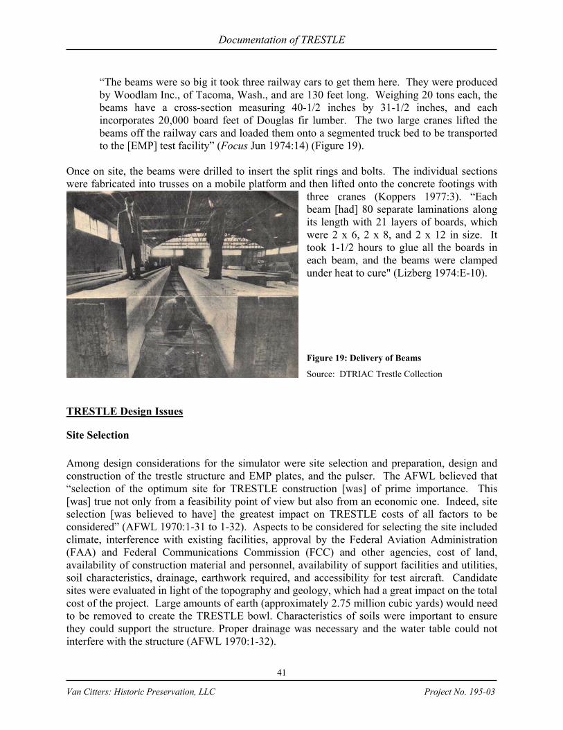
Documentation of TRESTLE
41
Van Citters: Historic Preservation, LLC Project No. 195-03
“The beams were so big it took three railway cars to get them here. They were produced by Woodlam Inc., of Tacoma, Wash., and are 130 feet long. Weighing 20 tons each, the beams have a cross-section measuring 40-1/2 inches by 31-1/2 inches, and each incorporates 20,000 board feet of Douglas fir lumber. The two large cranes lifted the beams off the railway cars and loaded them onto a segmented truck bed to be transported to the [EMP] test facility” (Focus Jun 1974:14) (Figure 19).
Once on site, the beams were drilled to insert the split rings and bolts. The individual sections were fabricated into trusses on a mobile platform and then lifted onto the concrete footings with
three cranes (Koppers 1977:3). “Each beam [had] 80 separate laminations along its length with 21 layers of boards, which were 2 x 6, 2 x 8, and 2 x 12 in size. It took 1-1/2 hours to glue all the boards in each beam, and the beams were clamped under heat to cure" (Lizberg 1974:E-10). Figure 19: Delivery of Beams
Source: DTRIAC Trestle Collection TRESTLE Design Issues
Site Selection Among design considerations for the simulator were site selection and preparation, design and construction of the trestle structure and EMP plates, and the pulser. The AFWL believed that “selection of the optimum site for TRESTLE construction [was] of prime importance. This [was] true not only from a feasibility point of view but also from an economic one. Indeed, site selection [was believed to have] the greatest impact on TRESTLE costs of all factors to be considered” (AFWL 1970:1-31 to 1-32). Aspects to be considered for selecting the site included climate, interference with existing facilities, approval by the Federal Aviation Administration (FAA) and Federal Communications Commission (FCC) and other agencies, cost of land, availability of construction material and personnel, availability of support facilities and utilities, soil characteristics, drainage, earthwork required, and accessibility for test aircraft. Candidate sites were evaluated in light of the topography and geology, which had a great impact on the total cost of the project. Large amounts of earth (approximately 2.75 million cubic yards) would need to be removed to create the TRESTLE bowl. Characteristics of soils were important to ensure they could support the structure. Proper drainage was necessary and the water table could not interfere with the structure (AFWL 1970:1-32).
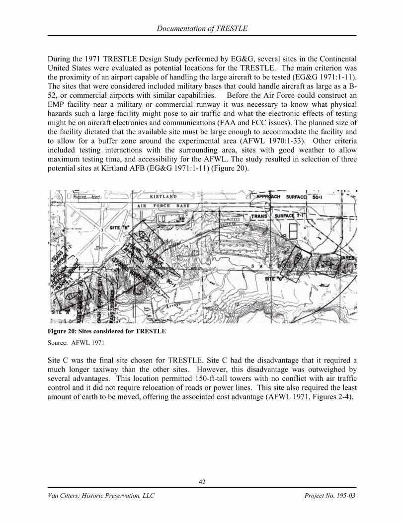
Documentation of TRESTLE
42
Van Citters: Historic Preservation, LLC Project No. 195-03
During the 1971 TRESTLE Design Study performed by EG&G, several sites in the Continental United States were evaluated as potential locations for the TRESTLE. The main criterion was the proximity of an airport capable of handling the large aircraft to be tested (EG&G 1971:1-11). The sites that were considered included military bases that could handle aircraft as large as a B-52, or commercial airports with similar capabilities. Before the Air Force could construct an EMP facility near a military or commercial runway it was necessary to know what physical hazards such a large facility might pose to air traffic and what the electronic effects of testing might be on aircraft electronics and communications (FAA and FCC issues). The planned size of the facility dictated that the available site must be large enough to accommodate the facility and to allow for a buffer zone around the experimental area (AFWL 1970:1-33). Other criteria included testing interactions with the surrounding area, sites with good weather to allow maximum testing time, and accessibility for the AFWL. The study resulted in selection of three potential sites at Kirtland AFB (EG&G 1971:1-11) (Figure 20).
Figure 20: Sites considered for TRESTLE
Source: AFWL 1971 Site C was the final site chosen for TRESTLE. Site C had the disadvantage that it required a much longer taxiway than the other sites. However, this disadvantage was outweighed by several advantages. This location permitted 150-ft-tall towers with no conflict with air traffic control and it did not require relocation of roads or power lines. This site also required the least amount of earth to be moved, offering the associated cost advantage (AFWL 1971, Figures 2-4).

Documentation of TRESTLE
43
Van Citters: Historic Preservation, LLC Project No. 195-03
Access to the site was created by a 50-ft wide towpath that extended from the east-west runway to the wood ramp. The towpath was shared with the HPD facility and was relocated when VPD-II was constructed (Cole 12 Nov 1976:4).
Figure 15: Final Site near other simulators.
Source: 377th Air Base Wing, Civil Engineering drawing files
In its original proposal, MDAC noted that the soils at the site “can vary radically within short distances due to the alluvial nature of the original soil deposits” and recommended complete and exhaustive soils investigations (Goetz 12 Jun 1975:1). The Preliminary Soil & Foundation Investigation Report of 1972 described the soil in the project area as uncemented or weakly cemented. It was characterized as generally firm for the upper 3 to 8 feet of selected borings, becoming cemented and very firm to hard under this layer; however, the poorly cemented layer extended down to about 48 feet in one boring (Goetz 11 Jun 1975:1). Before construction began, MDAC took 69 core samples, but the TRESTLE Program Manager believed that they were not sufficient, given the variability of the soil conditions at the site. The Program Manager requested a more thorough sampling and MDAC suggested postponing further soil investigations until the caissons were being drilled. Because the soil layers beneath the caissons were “of primary concern,” the AFWL technical staff recommended that additional core borings were necessary to “substantially increase confidence in the ability of the foundations to support the design weight of the glulam test platforms and ramps” (Futch 1 Apr 1974). Program documentation does not indicate whether the additional samples were taken. There were two choices for TRESTLE foundations; a raft spread footing and auger cast piles drilled to a depth to carry the design loads. The original approach was to use spread footings. The spread footings could not be over 5 ft by 5 ft in size under the test stand, ramp and towers, because the reinforcing bars in the concrete would begin to interfere with the EMP. The preliminary design from MDACs structural subconsultant, Krause, included a 7 ft spread footing. MDAC eventually used caissons; while either may have been suitable, AFWL would have preferred that MDAC completed the required soils tests to ensure the proper structural decision was made.
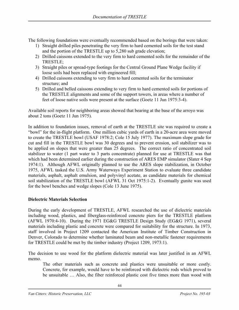
Documentation of TRESTLE
44
Van Citters: Historic Preservation, LLC Project No. 195-03
The following foundations were eventually recommended based on the borings that were taken:
1) Straight drilled piles penetrating the very firm to hard cemented soils for the test stand and the portion of the TRESTLE up to 5,280 sub grade elevation;
2) Drilled caissons extended to the very firm to hard cemented soils for the remainder of the TRESTLE;
3) Straight piles or spread-type footings for the Central Ground Plane Wedge facility if loose soils had been replaced with engineered fill;
4) Drilled caissons extending to very firm to hard cemented soils for the terminator structure; and
5) Drilled and belled caissons extending to very firm to hard cemented soils for portions of the TRESTLE alignments and some of the support towers, in areas where a number of feet of loose native soils were present at the surface (Goetz 11 Jun 1975:3-4).
Available soil reports for neighboring areas showed that bearing at the base of the arroyo was about 2 tons (Goetz 11 Jun 1975). In addition to foundation issues, removal of earth at the TRESTLE site was required to create a “bowl” for the in-flight platform. One million cubic yards of earth in a 20-acre area were moved to create the TRESTLE bowl (USAF 1978:2; Cole 15 July 1977). The maximum slope grade for cut and fill in the TRESTLE bowl was 30 degrees and to prevent erosion, soil stabilizer was to be applied on slopes that were greater than 25 degrees. The correct ratio of concentrated soil stabilizer to water (1 part water to 3 parts concentrate) planned for use at TRESTLE was that which had been determined earlier during the construction of ARES EMP simulator (Slater 4 Sep 1974:1). Although AFWL originally planned to use the ARES slope stabilization, in October 1975, AFWL tasked the U.S. Army Waterways Experiment Station to evaluate three candidate materials, asphalt, asphalt emulsion, and polyvinyl acetate, as candidate materials for chemical soil stabilization of the TRESTLE bowl (AFWL 31 Oct 1975:1-2). Eventually gunite was used for the bowl benches and wedge slopes (Cole 13 June 1975).
Dielectric Materials Selection During the early development of TRESTLE, AFWL researched the use of dielectric materials including wood, plastics, and fiberglass-reinforced concrete piers for the TRESTLE platform (AFWL 1970:4-10). During the 1971 EG&G TRESTLE Design Study (EG&G 1971), several materials including plastic and concrete were compared for suitability for the structure. In 1973, staff involved in Project 1209 contacted the American Institute of Timber Construction in Denver, Colorado to determine whether laminated beam and non-metallic fastener requirements for TRESTLE could be met by the timber industry (Project 1209, 1973:1). The decision to use wood for the platform dielectric material was later justified in an AFWL memo.
The other materials such as concrete and plastics were unsuitable or more costly. Concrete, for example, would have to be reinforced with dielectric rods which proved to be unsuitable … Also, the fiber reinforced plastic cost five times more than wood with
Documentation of TRESTLE
45
Van Citters: Historic Preservation, LLC Project No. 195-03
little weight savings … Glue-laminated members have significantly less checking and warpage than sawn timbers; thus the design is based on these glued-laminated members. No other analysis has been made recently, but the cost of the plastic used in the pulser modules rose drastically in 1974 while the wood costs rose more moderately (Freyer Nov 1975:1).
During the early conceptual design studies, AFWL performed tests on different woods and configurations to determine the best orientation of the wood in the test platform (Figure 21).
If the dielectric structure is wooden, the effects of its presence may be minimized by proper alignment of the structure wood grain. Thus, in designing a wooden floor for test object support for a horizontally polarized TRESTLE simulator the wood grain should be directed across the simulator as shown [parallel to the E field] to minimize field perturbations (AFWL 1970:2-59 & 2-60).
Figure 21: Field Geometry for TRESTLE Simulator Wood Members
Source: AFWL 1970 Early AFWL studies also included the compressive strength of various types and orientations of wood:
West Coast fir is recommended because of its dielectric characteristics … the compressive strength depends on the orientation of the grain. In select structural Douglas fir, for example, the allowable stress perpendicular to the grain is 415 psi, compared to 1,400 psi for compression parallel to the grain. Therefore, structural members and, in particular, the flooring system should be designed to minimize field perturbations without sacrificing strength (AFWL 1970: 4-10).
Another important lumber issue arose during the design of the TRESTLE: moisture content in glue-laminated timbers. The contracting source that could provide Douglas fir/Larch glulam would only bid on a moisture content of 12% and the Southern pine manufacturers would only bid on a moisture content of 16%, while the moisture equilibrium point for large wood members in the Albuquerque area was 7%. When wood with high moisture content is delivered to an area with a low relative humidity, the wood will check, deform, and shrink. The checking results in areas with a higher susceptibility to decay. The deformation and shrinkage can cause stresses within the members and affect the structural adequacy at member connections. The primary issues were longitudinal shrinkage that could affect erection tolerances and cross sectional
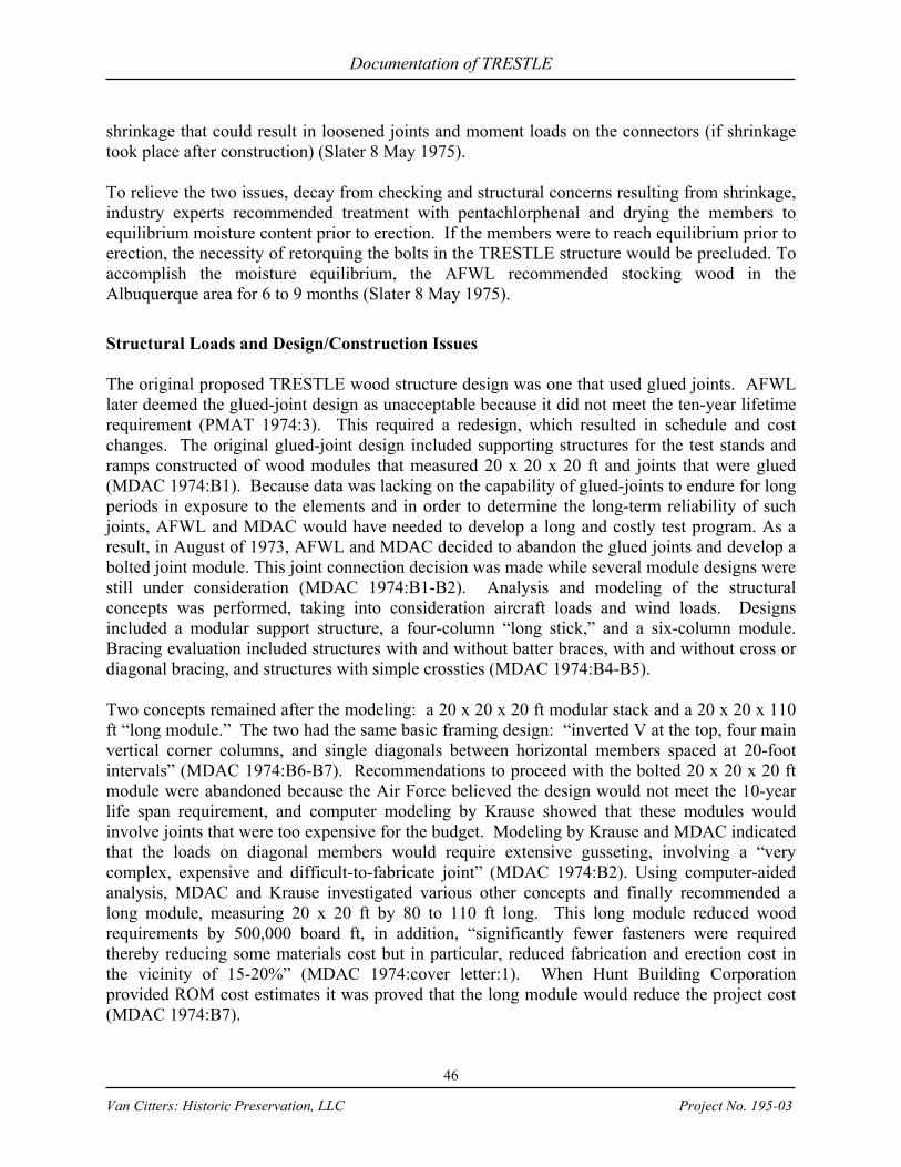
Documentation of TRESTLE
46
Van Citters: Historic Preservation, LLC Project No. 195-03
shrinkage that could result in loosened joints and moment loads on the connectors (if shrinkage took place after construction) (Slater 8 May 1975). To relieve the two issues, decay from checking and structural concerns resulting from shrinkage, industry experts recommended treatment with pentachlorphenal and drying the members to equilibrium moisture content prior to erection. If the members were to reach equilibrium prior to erection, the necessity of retorquing the bolts in the TRESTLE structure would be precluded. To accomplish the moisture equilibrium, the AFWL recommended stocking wood in the Albuquerque area for 6 to 9 months (Slater 8 May 1975).
Structural Loads and Design/Construction Issues The original proposed TRESTLE wood structure design was one that used glued joints. AFWL later deemed the glued-joint design as unacceptable because it did not meet the ten-year lifetime requirement (PMAT 1974:3). This required a redesign, which resulted in schedule and cost changes. The original glued-joint design included supporting structures for the test stands and ramps constructed of wood modules that measured 20 x 20 x 20 ft and joints that were glued (MDAC 1974:B1). Because data was lacking on the capability of glued-joints to endure for long periods in exposure to the elements and in order to determine the long-term reliability of such joints, AFWL and MDAC would have needed to develop a long and costly test program. As a result, in August of 1973, AFWL and MDAC decided to abandon the glued joints and develop a bolted joint module. This joint connection decision was made while several module designs were still under consideration (MDAC 1974:B1-B2). Analysis and modeling of the structural concepts was performed, taking into consideration aircraft loads and wind loads. Designs included a modular support structure, a four-column “long stick,” and a six-column module. Bracing evaluation included structures with and without batter braces, with and without cross or diagonal bracing, and structures with simple crossties (MDAC 1974:B4-B5). Two concepts remained after the modeling: a 20 x 20 x 20 ft modular stack and a 20 x 20 x 110 ft “long module.” The two had the same basic framing design: “inverted V at the top, four main vertical corner columns, and single diagonals between horizontal members spaced at 20-foot intervals” (MDAC 1974:B6-B7). Recommendations to proceed with the bolted 20 x 20 x 20 ft module were abandoned because the Air Force believed the design would not meet the 10-year life span requirement, and computer modeling by Krause showed that these modules would involve joints that were too expensive for the budget. Modeling by Krause and MDAC indicated that the loads on diagonal members would require extensive gusseting, involving a “very complex, expensive and difficult-to-fabricate joint” (MDAC 1974:B2). Using computer-aided analysis, MDAC and Krause investigated various other concepts and finally recommended a long module, measuring 20 x 20 ft by 80 to 110 ft long. This long module reduced wood requirements by 500,000 board ft, in addition, “significantly fewer fasteners were required thereby reducing some materials cost but in particular, reduced fabrication and erection cost in the vicinity of 15-20%” (MDAC 1974:cover letter:1). When Hunt Building Corporation provided ROM cost estimates it was proved that the long module would reduce the project cost (MDAC 1974:B7).

Documentation of TRESTLE
47
Van Citters: Historic Preservation, LLC Project No. 195-03
As a result, the long modules became the basis for the bent design. Their dimensions were 19 x 19 x 100 ft and were described as: “A single bent is a slice through one face of two modules, with associated horizontal and cross ties and when necessary associated batters with their cross bracing” (AFWL n.d. e: 1-16) (Figure 22).
Figure 22: Construction Modules and Joints
Source: MDAC 1974
Once AFWL determined that bolts should be used for joint connections, they began to evaluate how the connections should be made. They developed a method using split ring connectors and
dielectric bolts. Split ring connectors (Figure 23) are ring-shaped metal inserts that collect the load from one timber member and transfer it to the other. A ring is split so that it can be fitted into a circular groove on the meeting face of each timber. The groove is slightly larger in diameter than the split ring and the split of the ring opens when the ring is sprung into the groove. The gap that is created at the split may open or close as the wood expands and contracts, based on its moisture content, and this ensures that the metal ring and wood are always in contact (Harris 2000:867; Timber Best Practice 2003).
Figure 23: Split-Ring Connector
Source: Harris 2000 Because the split ring connectors were metal, there was concern over them affecting the electromagnetic tests at TRESTLE. As such, the split ring connectors were located so that the H-field was always in the plane of the ring, so that the incident field induced only a small magnetic moment in the rings. In addition, the rings were small with respect to the “radian wavelength of the incident field” so their response was similar to an electric dipole. The result was that the rings would slightly reduce the electric field in the interior of the test stand, which in turn added a slight increase to the average dielectric constant that was already present in the wood structure (Prather 1974:22).

Documentation of TRESTLE
48
Van Citters: Historic Preservation, LLC Project No. 195-03
In addition to the split rings, AFWL and MDAC had to determine which dielectric bolt to select for timber joints. One candidate was the Valox, a thermoplastic polyester resin. The Valox bolts used upset threads, i.e. – they were thickened at one end. The Valox bolt upset threads required oversized holes, and AFWL and the Air Force were concerned that this could create a situation in which the split-ring connectors might realize their maximum loads before the bolts came into bearing. Eventually, Permali was chosen as the nut/bolt material. Permali began to be manufactured in the 1930s and is a composite material made from wood and phenolic resin. It is manufactured by immersing beech veneers (1/32nd of an inch thick) in a phenolic resin solution and then impregnating the wood through a vacuum process. Once the wood is thoroughly impregnated,
the laminate would be consolidated with heat and pressure in a press. The resulting material has deep mahogany color and a plywood look, but it is much harder than wood with a much higher density (Plastics Museum 2003) (Figure 24). The phenolic-impregnated fasteners have a strength-to-weight ratio of high tensile steel (Civil Engineering 1977:20). Permali, Inc., of Pleasant, Pennsylvania, a fabricator of non-metallic products, was awarded the contract for the platform’s “wooden” fasteners and other components. There are over 150,000 bolts in TRESTLE with lengths varying from 20 to 60 in.
Figure 24: TRESTLE bolt detail
Source: DTRIAC Trestle Collection Once the bent concept with split rings and dielectric bolts was set, the contractor began structural load tests for fabrication of TRESTLE. In late May of 1974 Captain Goetz and Mr. Ungvarsky visited MDAC to review the testing program to verify allowable strengths of components to be used in the fabrication of the TRESTLE facility. The conclusion was that MDAC carried out their test program with “little forethought or planning” and that MDAC agreed that it “showed little planning and a lack of grasp of conducting meaningful tests …” (Goetz and Ungvarsky 21 May 1974:1). Although the Vice President for Engineering at MDAC agreed to improve testing, during the process it became evident to the AFWL staff that there was little intention of actually improving the testing to meet the minimum acceptable standards, such as those of the American Society for Testing Materials (ASTM). The MDAC contract called for materials to be tested in accordance with ASTM. The AFWL staff believed it was fair and reasonable to expect load deflection curves for the connector system at TRESTLE also be defined by consistent testing procedures defined by ASTM, because the design parameters for TRESTLE were to be set by the properties defined in testing. AFWL felt

Documentation of TRESTLE
49
Van Citters: Historic Preservation, LLC Project No. 195-03
it was important to have consistent engineering data through tests based on ASTM standards to ensure the parameters were sound (Goetz and Ungvarsky 21 May 1974:3). At the end of May 1974 MDAC submitted a design package for the TRESTLE wood systems. The package was determined inadequate because it was over conservative in some areas and under conservative in others. The overall problems were:
1) The calculations were vague and incomplete. 2) The design connection allowable capacities were under conservative and therefore
unacceptable, because MDAC used full steel bolt and split ring values to calculate Permali bolts with metal split rings and assumed the joints were fixed.
3) The wind loading was not in accordance with the scope of work. 4) Several connections in bent joints were overstressed by factors ranging from 3% to
74% (Slater 30 May 1974:1). Because most of the existing industry structural calculations were based on steel bolts, engineers recommended that in situations where dielectric bolts with split-ring connectors were to be used, the allowable stresses for steel bolts be reduced by 20% to approximate the characteristics of dielectric bolts (Bracher 1974:2). As such, MDAC and AFWL investigated bolted joints and more specifically, the respective contributions of bolts and split-ring connectors.
Upon my initial review of joint design methods for split-ring fasteners, it was felt that the use of dielectric bolts, in lieu of steel, when used in conjunction with the standard 4” TECO split-ring connectors in the wood structures joint design, would result in a reduction of the load carrying capacity of the joint. …Results of these tests [split-ring connectors alone, steel bolts alone, and connectors and bolts acting together] indicated that the maximum test load for the connector acting alone is approximately 81% of the test load for the steel bolt and connector acting together. Furthermore, it is noted that the connector acting alone will reach its maximum load value at a joint slip of less than 1/8” (Bracher 1974:1-2).
In addition to evaluating the split rings and Permali bolts, in April of 1975, AFWL contacted the American Plywood Association (APA) to gain information about the engineering analysis of plywood gussets with steel split rings. At the time, AFWL was considering a small testing program to develop data on how plywood gussets and steel split rings transfer loads in wood timber joints and wanted to collect information about the materials and how to conduct their tests. The gusset materials they were looking into included: marine plywood, Fin Ply, Permali, ordinary glue laminates, and APA Group 1 plywood (Cole 25 April 1975). Each of these materials was a composite product made of layers of high strength wood bonded together. Marine grade plywood is manufactured from Okoume or another tropical wood with a fungicide in the glue between the layers; it is generally used in marine applications. Fin Ply is plywood made with Finnish birch with zero voids, making the panel high density. As with the structural components for TRESTLE, the glue-laminated gussets would have been made from a structural composite product glued from selected grades of kiln-dry laminating lumber, or “laminations,” with the grain of all pieces parallel to the longitudinal axis of the member. In manufacturing, each short-length lumber is end-jointed by end (finger or scarf) joints to form a long-length lamination. These laminations are then face-bonded with a wet-use adhesive.

Documentation of TRESTLE
50
Van Citters: Historic Preservation, LLC Project No. 195-03
MDAC tested some gussets at their Huntington Beach facility: two tests with Fin Ply and three with marine plywood, using Valox bolts. The design MDAC specified after the test was 2¼ in thick Fin Ply with Permali bolts and 4 in split rings manufactured by Teco. Permali bolts had not been tested by MDAC and AFWL questioned whether Fin Ply was a better material than APA Group 1 Species Plywood, a material that was more readily available in the U.S. While Fin Ply is very dense, APA Group 1 plywood is manufactured from Beech or Douglas fir and is the strongest and stiffest grade of plywood in available the U.S. The issue with regard to Fin Ply versus APA Group 1 plywood was most likely raised due to cost. From the MDAC test results and design recommendation, Captain Goetz and Mr. Ungvarsky judged the MDAC testing to be inadequate. In order to obtain high quality testing procedures, AFWL surveyed industry and testing laboratories. The best information they could find on split ring/bolt joints was that conducted by Timber Engineering Co. at Stanford University in 1936, a test which used steel bolts and contemporary plywood (plywood available in the 1970s used different species and grades and would therefore have different structural characteristics from a 1930s plywood). The summary of the AFWL research effort was that a well-planned test program was important in order to accurately determine the plywood/split ring allowable loads for the TRESTLE design (Slater 3 May 1975). While a thorough test program was desirable, AFWL determined that they could set allowable loads based on published information to reduce the cost of such testing. They began with the existing tests that used steel bolts in sawn and glue-laminated timbers, which were published in the National Design Specification for Stress-Grade Lumber and Its Fastenings (NDS). The NDS standards combined with Forest Products Laboratory (FPL) Report No. 865 led AFWL and MDAC to agree on the loads for split ring connectors used in a shear connection joint of glue laminated lumber, as long as MDAC would consider the maximum loads and establish the minimum working section of the gusset material through minor testing. If a gusset material were used other than glue laminates, MDAC would be required to perform extensive tests, because the NDS and FPL data only addressed glue laminated lumber and therefore calculations could only maintain a desirable level of accuracy if that type of gusset material. If MDAC was to choose an alternate gusset material they would have to test for the limits of material thickness, edge distances, and connector spacing (Slater 4 May 1975). In June of 1975, based on the NDS and FPL data, Krause developed a method to calculate the split ring shear connector loads for the gusset plates. AFWL requested that Krause submit connector loads for the three most heavily loaded gusset plates, using allowable loads no less than the loads for the glue-laminated members. They also requested that MDAC analyze these using a computerized finite method to determine the maximum and minimum normal and shear stresses (Cole 16 June 1975). The AFWL Mechanical Test Laboratory in Hangar 1001 on the Kirtland AFB flightline was also used for numerous materials tests to support engineering decisions. “Considerable engineering data was obtained through bolt tests, split ring tests and glue-line shear tests” (Merkle 12 Jan 1979).

Documentation of TRESTLE
51
Van Citters: Historic Preservation, LLC Project No. 195-03
In May 1974, MDAC submitted a design for the horizontal simulator that did not include supporting calculations with regard to wind loading (Futch 3 May 1974). In addition to connector loads, wind played an important role in the structural design of TRESTLE. Each aircraft planned for testing had different tolerances for wind. The EC-135 could be towed up to 65 knots (74.75 mph); the 747 (E-3 and E-4) could stand a 90-degree crosswind of 100 knots (115 mph) when fully fueled. The C-5A had to be prepared for mooring in winds of 25 knots (28.75 mph) and required mooring for winds above 40 knots (46 mph). The B-52 could not be towed if the wind was above 40 knots (46 mph) and if it was on the test stand when winds reached that speed, all openings were to be closed, the aircraft grounded and its nose turned into the wind (Sherwood 25 Mar 76:1). A wind speed of 46 mph was the lowest common denominator and to provide a safety margin, the wind limitation for aircraft on the test stand was set at 40 mph. In 1976, after the B-1 had been added to the testing program and as part of planning for its testing, analysis was being conducted to weigh the benefits of running aircraft engines during testing versus the problems that might be caused by the vibration effects on the test facilities and surrounding structures (Tyler 1976a:1). Structural considerations began to include the unlikely possibility that the facility might have to be capable of restraining the huge aircraft if its engines malfunctioned and switched to maximum power during test (Tyler 1976b:1). In addition to the structural characteristics of TRESTLE itself, MDAC was also instructed to work out the details of aircraft tiedown (Slater 30 May 1974:3-4). In July of 1975, the TRESTLE Program Office approved a T-ROD for aircraft tiedown that included tiedown cleats on a grid of 10 ft by 10 ft within a forty-ft circle at the center of the test stand and a grid of 21 ft by 21 ft outside the inner circle. Each cleat was to be anchored by a nylon strap and looped around the girder that passed below (Cole 22 Jul 1975). MDAC completed structural calculations and computer modeling for TRESTLE joints using the defined 40 mph wind load and bolted gussets with split ring connectors. MDAC developed its modeling using fixed joints, whereas bolted wood joints are typically calculated as pinned joints, because it is extremely difficult to make such a joint fixed in reality. A fixed joint completely restrains rotations and translations in any direction, whereas wood tends to shrink, check, and twist, which changes the condition at the connection. Pinned joints allow attached members to rotate, which results in maximum bending forces at the middle of a beam, but no bending forces at the joint. A fixed joint can accommodate some of the forces of the beam, which reduces the forces in the middle of the beam. Therefore, a fixed joint allows for smaller beams. Using a fixed joint calculation for TRESTLE resulted in higher moments in the joints than would realistically occur in a pinned joint. If the calculations had been used for the design, the load carrying members would have been undersized (Schneider 2003). In order to develop a new model and accurate structural characteristics, the TRESTLE Wood Systems Joint Task Force at the TRESTLE Program Office, in collaboration with Don Neal and Doug Stadelmann, the Forest Products Association Laboratory and the National Forest Products Association, worked with MDAC to agree on the following:
1) Wind loading using a 40 mph wind to meet the “seventh power curve from the AFM [Air Force Manual] 88-3,” instead of the UBC [Uniform Building Code].
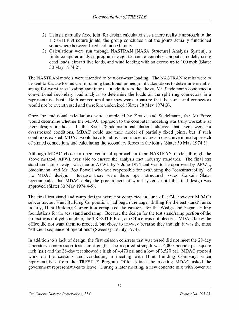
Documentation of TRESTLE
52
Van Citters: Historic Preservation, LLC Project No. 195-03
2) Using a partially fixed joint for design calculations as a more realistic approach to the TRESTLE structure joints; the group concluded that the joints actually functioned somewhere between fixed and pinned joints.
3) Calculations were run through NASTRAN [NASA Structural Analysis System], a finite computer analysis program design to handle complex computer models, using dead loads, aircraft live loads, and wind loading with an excess up to 100 mph (Slater 30 May 1974:2).
The NASTRAN models were intended to be worst-case loading. The NASTRAN results were to be sent to Krause for his use in running traditional pinned joint calculations to determine member sizing for worst-case loading conditions. In addition to the above, Mr. Stadelmann conducted a conventional secondary load analysis to determine the loads on the split ring connectors in a representative bent. Both conventional analyses were to ensure that the joints and connectors would not be overstressed and therefore undersized (Slater 30 May 1974:3). Once the traditional calculations were completed by Krause and Stadelmann, the Air Force would determine whether the MDAC approach to the computer modeling was truly workable as their design method. If the Krause/Stadelmann calculations showed that there were no overstressed conditions, MDAC could use their model of partially fixed joints, but if such conditions existed, MDAC would have to adjust their model using a more conventional approach of pinned connections and calculating the secondary forces in the joints (Slater 30 May 1974:3). Although MDAC chose an unconventional approach in their NASTRAN model, through the above method, AFWL was able to ensure the analysis met industry standards. The final test stand and ramp design was due to AFWL by 7 June 1974 and was to be approved by AFWL, Stadelmann, and Mr. Bob Powell who was responsible for evaluating the “constructability” of the MDAC design. Because there were these open structural issues, Captain Slater recommended that MDAC delay the procurement of wood systems until the final design was approved (Slater 30 May 1974:4-5). The final test stand and ramp designs were not completed in June of 1974, however MDACs subcontractor, Hunt Building Corporation, had begun the auger drilling for the test stand/ ramp. In July, Hunt Building Corporation completed the caissons for the Wedge and began drilling foundations for the test stand and ramp. Because the design for the test stand/ramp portion of the project was not yet complete, the TRESTLE Program Office was not pleased. MDAC knew the office did not want them to proceed, but chose to anyway because they thought it was the most “efficient sequence of operations” (Sweeney 19 July 1974). In addition to a lack of design, the first caisson concrete that was tested did not meet the 28-day laboratory compression tests for strength. The required strength was 4,000 pounds per square inch (psi) and the 28-day test showed a high of 4,470 psi and a low of 3,520 psi. MDAC stopped work on the caissons and conducting a meeting with Hunt Building Company; when representatives from the TRESTLE Program Office joined the meeting MDAC asked the government representatives to leave. During a later meeting, a new concrete mix with lower air

Documentation of TRESTLE
53
Van Citters: Historic Preservation, LLC Project No. 195-03
entrainment was proposed. As a result, MDAC initiated better control of sampling and specified the new concrete mix (Sweeney 19 July 1974; Sweeney 22 July 1974). In addition, in July of 1974, the caisson base plate anchor bolt connection was determined by TRESTLE Program Office to be inadequate. The MDAC drawings were not to scale and when Air Force staff analyzed them, they realized that the MDAC design incorporated the anchor bolt and the caisson rebar in the same location. The caisson diameter was too small to incorporate the anchor bolts as drawn; as such, the TRESTLE Program Office recommended that the contractor stop work until an alternative was developed. The design diameter for the caissons was 30 in, but Hunt Building Corporation poured them at 32 in. Because Hunt Building Corporation could not maintain a tight tolerance in drilling and location (some had been poured 2 in off center), they had recommended to MDAC that the caissons be poured at 36 in diameter to compensate. Krause had also recommended this change to MDAC. MDAC disregarded the contractor’s request and engineer’s suggestion to adjust the diameter of the caissons. This left the TRESTLE with 32-in caissons that were not in the locations necessary to carry the design structural loads and resulted in a conflicting rebar/anchor bolt situation (Slater 29 July 1974a; Slater 29 July 1974b). MDAC requested a new design that allowed the bolts to be bent in order to fit with the existing caisson diameter. At an on-site meeting, AFWL emphasized the importance of placing the anchor bolts in a vertical position rather than bending the bolts to make the existing caisson design work. While bending the bolts would have been convenient for MDAC, bending would have caused overstresses in the concrete of the caissons (Slater 29 July 1974a). When AFWL rejected bending the bolts, MDAC proposed to correct the problem by increasing the rebar diameter and bending it slightly to allow for the proper positioning of the anchor bolts (Slater 29 July 1974a). Captain Slater analyzed the loads given the existing caisson situation and determined that the best solution would be to redesign the base plate and anchor bolt positioning. He developed a design that would allow for proper alignment and vertical positioning of the anchor bolts. In the NASTRAN model for TRESTLE, high moments existed in the plane parallel to the longitudinal axis of the bent. So, Captain Slater recommended that the bolts be moved in the transverse plane to a point where they could be mated with the base plate without bending or overstressing the caisson concrete (Slater 29 July 1974a). After proposing the anchor bolt design change that would provide for structural adequacy without repouring the caissons, Captain Slater stated:
The problem [with the anchor bolts] is indicative of a greater discrepancy in MDAC’s approach to facility design. MDAC continually disregards design detail and disregards the recommendations of experts in the various engineering areas. Even when a problem is identified, MDAC proceeds on inadequate design information. MDAC must be required [to] pace construction efforts with design efforts. High program costs are inevitable when construction proceeds [sic] design (Slater 29 July 1974a).

Documentation of TRESTLE
54
Van Citters: Historic Preservation, LLC Project No. 195-03
The TRESTLE Program Office and MDAC compromised on a solution where grout sleeves could be permitted if at least ½ inch of grout were kept between the bolt and grout sleeve and if the anchor bolts were tied together. Changing the size of the top of the caisson to 36 in in diameter and 24 in deep provided sufficient edge distance and permitted full UBC allowable capacity for the anchor bolts (Cole 30 Aug 1974:1-2). The new design was accepted by MDAC, and Hunt Building Corporation was requested to expand the diameter of the caissons for new pours, where the caisson would not provide minimum rebar clear coverage. In addition, MDAC was required to furnish all calculations for the new design to the Air Force (Slater 29 July 1974a). After construction of the test stand, ramp, and pulser support structures were removed from the MDAC contract and re-contracted with Allen M. Campbell, new specifications, methods for construction, and contracting procedures were put in place. Specification ES7811600, published on 1 August 1975, established the requirements for wood procurement, design, fabrication, and erection of the test stand and ramp for the horizontal simulator (AFWL 1 August 1975). This was only one of many specifications for the many systems and subsystems. For example, in November of 1976, data was being refined on parameters for loading on the tension guys, steel down guys, transmission line support tower antenna guys and the transmission line cables for inclusion in the transmission line subsystem construction specification (Schmidt 1976). In addition, a laboratory test was also developed to discern the friction coefficient of rubber on painted surfaces to verify the ability to rotate the C-5A landing gear without moving the aircraft or placing it in the kneeled position (Cole 26 Sep 1974). MDAC completed tests to demonstrate that high gloss epoxy and uncoated surfaces had the lowest values and, although MDAC did not make a specific recommendation, it was believed that a high gloss epoxy would be suitable for use (Shover 1975).
TRESTLE Electromagnetic Environment Features Under the original concept for TRESTLE, the site was envisioned as one with a number of support buildings and separate pulser structures (Figure 10). The support buildings were to include a data acquisition structure with a double-walled shield room and a building for peripheral pulser equipment. There were two pulser arrays on either side of the test stand platform with transmission lines running from a point in the middle of the platform to the pulsers, then out, and around the platform to the termination end of the ramp. Eventually the triangle that was formed from the central platform lines to the pulsers became the Wedge, which served as the stand for the pulsers and the facility that housed the support operations (Figure 25). The Wedge also served as part of the pulser transmission and included steel I-beam construction with wire mesh extending upward from the platform level (Figure 2) (AFWL 1970:1-39–1-40). Using figures of merit, the TRESTLE simulator concept was developed as bounded wave. In a bounded wave simulator a large transmission line is driven by a high voltage pulser.
When the pulser is fired, an electromagnetic wave propagates down the line, simulating the EMP from a nuclear explosion. By making the spacing between the line elements
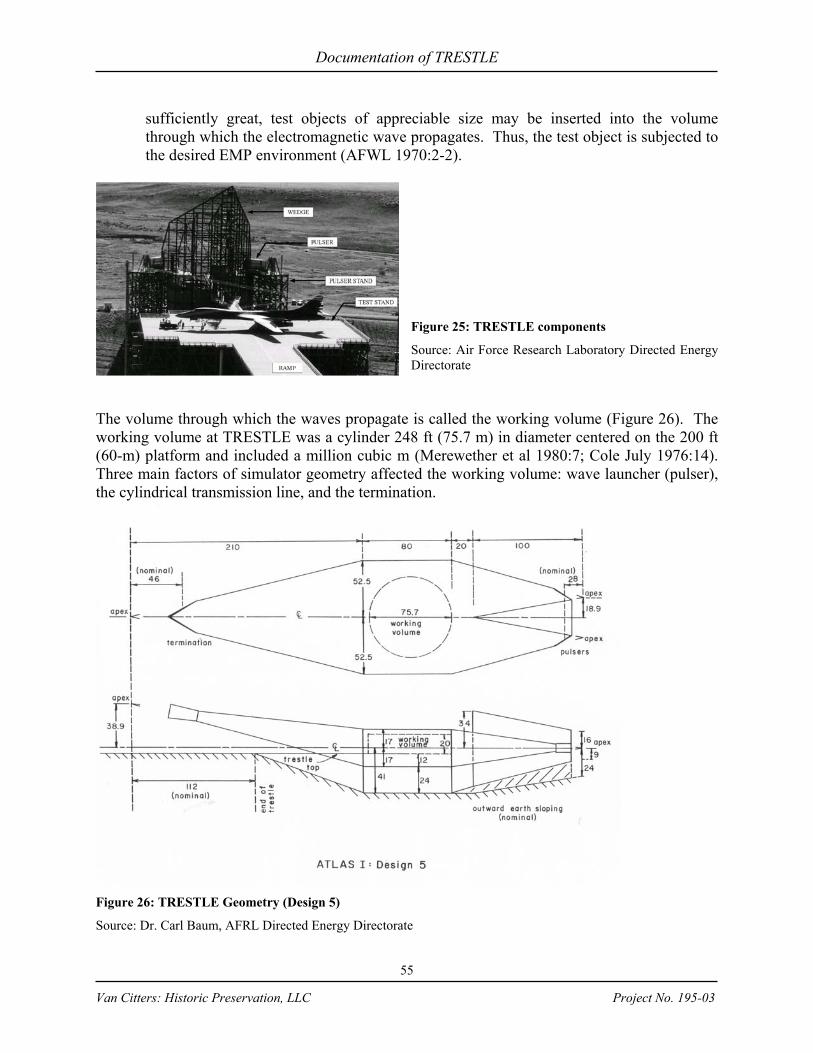
Documentation of TRESTLE
55
Van Citters: Historic Preservation, LLC Project No. 195-03
sufficiently great, test objects of appreciable size may be inserted into the volume through which the electromagnetic wave propagates. Thus, the test object is subjected to the desired EMP environment (AFWL 1970:2-2).
Figure 25: TRESTLE components
Source: Air Force Research Laboratory Directed Energy Directorate
The volume through which the waves propagate is called the working volume (Figure 26). The working volume at TRESTLE was a cylinder 248 ft (75.7 m) in diameter centered on the 200 ft (60-m) platform and included a million cubic m (Merewether et al 1980:7; Cole July 1976:14). Three main factors of simulator geometry affected the working volume: wave launcher (pulser), the cylindrical transmission line, and the termination.
Figure 26: TRESTLE Geometry (Design 5)
Source: Dr. Carl Baum, AFRL Directed Energy Directorate
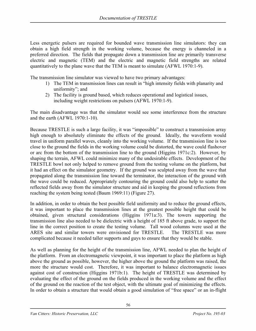
Documentation of TRESTLE
56
Van Citters: Historic Preservation, LLC Project No. 195-03
Less energetic pulsers are required for bounded wave transmission line simulators: they can obtain a high field strength in the working volume, because the energy is channeled in a preferred direction. The fields that propagate down a transmission line are primarily transverse electric and magnetic (TEM) and the electric and magnetic field strengths are related quantitatively to the plane wave that the TEM is meant to simulate (AFWL 1970:1-9). The transmission line simulator was viewed to have two primary advantages:
1) The TEM in transmission lines can result in “high intensity fields with planarity and uniformity”; and
2) The facility is ground based, which reduces operational and logistical issues, including weight restrictions on pulsers (AFWL 1970:1-9).
The main disadvantage was that the simulator would see some interference from the structure and the earth (AFWL 1970:1-10). Because TRESTLE is such a large facility, it was “impossible” to construct a transmission array high enough to absolutely eliminate the effects of the ground. Ideally, the waveform would travel in uniform parallel waves, cleanly into the working volume. If the transmission line is too close to the ground the fields in the working volume could be distorted, the wave could flashover or arc from the bottom of the transmission line to the ground (Higgins 1971c:2). However, by shaping the terrain, AFWL could minimize many of the undesirable effects. Development of the TRESTLE bowl not only helped to remove ground from the testing volume on the platform, but it had an effect on the simulator geometry. If the ground was sculpted away from the wave that propagated along the transmission line toward the terminator, the interaction of the ground with the wave could be reduced. Appropriately contouring the ground could also help to scatter the reflected fields away from the simulator structure and aid in keeping the ground reflections from reaching the system being tested (Baum 1969:11) (Figure 27). In addition, in order to obtain the best possible field uniformity and to reduce the ground effects, it was important to place the transmission lines at the greatest possible height that could be obtained, given structural considerations (Higgins 1971a:3). The towers supporting the transmission line also needed to be dielectric with a height of 185 ft above grade, to support the line in the correct position to create the testing volume. Tall wood columns were used at the ARES site and similar towers were envisioned for TRESTLE. The TRESTLE was more complicated because it needed taller supports and guys to ensure that they would be stable. As well as planning for the height of the transmission line, AFWL needed to plan the height of the platform. From an electromagnetic viewpoint, it was important to place the platform as high above the ground as possible, however, the higher above the ground the platform was raised, the more the structure would cost. Therefore, it was important to balance electromagnetic issues against cost of construction (Higgins 1971b:1). The height of TRESTLE was determined by evaluating the effect of the ground on the fields produced in the working volume and the effect of the ground on the reaction of the test object, with the ultimate goal of minimizing the effects. In order to obtain a structure that would obtain a good simulation of “free space” or an in-flight
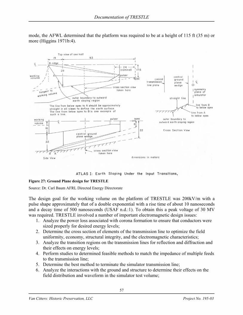
Documentation of TRESTLE
57
Van Citters: Historic Preservation, LLC Project No. 195-03
mode, the AFWL determined that the platform was required to be at a height of 115 ft (35 m) or more (Higgins 1971b:4).
Figure 27: Ground Plane design for TRESTLE
Source: Dr. Carl Baum AFRL Directed Energy Directorate The design goal for the working volume on the platform of TRESTLE was 200kV/m with a pulse shape approximately that of a double exponential with a rise time of about 10 nanoseconds and a decay time of 500 nanoseconds (USAF n.d.:1). To obtain this a peak voltage of 30 MV was required. TRESTLE involved a number of important electromagnetic design issues:
1. Analyze the power loss associated with corona formation to ensure that conductors were sized properly for desired energy levels;
2. Determine the cross section of elements of the transmission line to optimize the field uniformity, economy, structural integrity, and the electromagnetic characteristics;
3. Analyze the transition regions on the transmission lines for reflection and diffraction and their effects on energy levels;
4. Perform studies to determined feasible methods to match the impedance of multiple feeds to the transmission line;
5. Determine the best method to terminate the simulator transmission line; 6. Analyze the interactions with the ground and structure to determine their effects on the
field distribution and waveform in the simulator test volume;

Documentation of TRESTLE
58
Van Citters: Historic Preservation, LLC Project No. 195-03
7. Develop a fast risetime for the TEM and low jitter in the output switches of the pulser (AFWL 1970: 1-40–1-41).
Corona formation was an issue at TRESTLE. Development of a corona could result in decreased energy to the test volume, affecting the ability to obtain the desired field intensities. It could also lead to the generation of a streamer that could result in a dielectric breakdown between the conductors or the conductor and the test object. There was a high possibility of corona formation occurring close to the pulser, so the lines at that point were enclosed with a high dielectric strength gas near the apex of the line to prevent corona from forming (AFWL 1970:1-23). During the early conceptual design, the pulsers were planned to put a peak voltage of five MV into a 175 to 200 Ohm (Ω) line. To do so the pulsers would have to store between 15 and 20 kilojoules (AFWL 1970:2-70). Later, the horizontal simulator pulse generators were intended to store 210 kilojoules and the vertical 27 kilojoules (USAF 1973:4). TRESTLE was constructed with the five MV pulsers and a 150 Ω line. In the early conceptual design for TRESTLE, AFWL stated, “Pulsers for parallel plate lines with outputs of five MV or greater have been built before. Consequently, the pulser design, from a high voltage standpoint, is a relatively straightforward problem” (AFWL 1970:1-31). The development of the TRESTLE pulsers and working volume turned out to be not such a straightforward effort. The pulsers that were ultimately designed for TRESTLE were two identical five MV pulser modules mounted on either side of the Wedge. The pulsers were charged to opposite polarities: one side would launch a positive pulse and the other a negative pulse. When they were fired, they would launch an electromagnetic wave into a conic transition on either side of the Wedge. At the apex of the Wedge, the waves would unite to form a TEM plane (combined waveform of double exponential character) and then propagate into the working volume (Merewether et al 1980:10; Giri & Sands 1984:2). As the wave propagated past the Wedge, the two waves added across the parallel plate (150 Ω transmission line) to develop the appropriate EMP environment within the working volume (Graham and Giri 1979: 3). To speed up the transfer of energy from the pulser into the transmission line, the pulsers included a monocone output switch and a 50.5 stage Marx generator with an array of peaking capacitors. A Marx generator is set of large capacitors charged in parallel, which results in developing a uniform voltage across all the generator capacitors. The capacitors are reconnected in series with interconnecting spark gaps. The sum of voltages appears across the Marx generator output. The energy is released from the Marx by simultaneously triggering several switches, which results in a cascade of the remaining switches. The peaking capacitors decreased the pulse rise time, allowing the pulse to move into the transmission line more quickly (Merewether et al 1980:10–11). The main pulser switch was a monocone design with an adjustable spark gap that separated the end of the cone from the ground plane. It was necessary to reduce the jitter in the output switch of the Marx generator peaking capacitor in order to create a smooth wave on the output pulse. This was done by installing point plane gas switches, which include gas as insulation. The breakdown strength of atmospheric air was not sufficient to insulate a low-inductance Marx

Documentation of TRESTLE
59
Van Citters: Historic Preservation, LLC Project No. 195-03
generator, so SF6 was used to provide the protection (AFWL 1970:1:28). The switch and SF6 were enclosed in a cylindrical fiberglass canister and pressurized to 100 psi (100,000 liters at 1 atmosphere) during pulser operations. The time it took to fire the main switch spark gap of the pulser was referred to as the firing time and it was adjusted by altering the separation of the cone and ground plane inside the switch: the smaller the gap, the faster the firing time. The firing time during pulser test was about 90 nanoseconds. While the AFWL was able to adjust the firing time for each pulser, the switches on the two pulsers could not fire at exactly the same time. This was referred to as pulser asynchronism and was considered a key variable in the field quantity of the working volume (Merewether et al 1980:11–16). Asynchronism occurred in 40% of the pulser test shots and if not addressed could result in:
1) Frequency domain notches in the simulated fields; 2) Field asymmetries in the working volume (with respect to the centerline); 3) Rise time degradation and consequent loss of high frequency components; and 4) Loss of peak amplitude in simulated fields (Giri & Sands 1984:4).
Other factors that affected the pulser waveform (Figure 28) and simulator performance goals, included peak amplitude, prepulse, notch effective decay time, rise time, and frequency content. Although these factors resulted in some variations, the fields at TRESTLE were relatively uniform over the working volume. However, the field mapping team recommended that the peaking capacitor array be redesigned to provide twice the tested capacitance to yield a substantial waveform improvement with regard a notch that was developing due to asynchronism. In addition, they recommended that the switches in the Marx generator and the main switch be better matched to increase rise time (Merewether et al 1980:11–16). The solution to the asynchronism was to install improved Marx switches with newer radiating switches. The cost for this was estimated between $50,000 and $100,000 (Giri and Sands 1984:8).
Figure 28: Pulser waveform
Source: AFWL Integrated Electromagnetic Pulse Facilities Brochure In addition to the 5 MV pulsers, AFWL chose to use cylindrical transmission lines, which were calculated as infinite lossless transmission with the primary mode of propagation as TEM. In the TEM mode, it is “especially simple” to develop a field distribution associated with the current and voltage waveforms traveling down a line. To calculate this AFWL used Laplace’s equation (∇2 ϕ = 0), in two dimensions using the appropriate boundary conditions. By doing so, the problem was reduced electrostatics, because the field distribution is the same for any cross-

Documentation of TRESTLE
60
Van Citters: Historic Preservation, LLC Project No. 195-03
section with differences only in “relative intensity as a function of time or of distance down the line” (AFWL 1970:2-6). Although the AFWL stated that Laplace’s equation is especially simple, they later state the mapping the field can be “rather formidable.” To actually map the waveforms AFWL used “… numerical computation with high speed digital computers, approximate methods based on analog plotting equipotentials, and/or other approximation of variational techniques” (AFWL 1970: 2-17). A lossless transmission line with uniform characteristic impedance develops a pulse shape and amplitude that does not change from point to point along the line and the electric and magnetic fields are bound to the current in the conductors and voltage across the lines. The transmission lines for TRESTLE were developed into two parallel arrays that served as parallel plates to send a waveform into the testing volume. These arrays were relatively inexpensive, weighed less than actual plates, and were effective for outdoor installation because of their wind loading characteristics, i.e. – the wind could pass through the arrays, whereas a true plate would act more like a sail (AFWL 1970:2-17). Some of the factors important in the design of a bounded wave simulator include field uniformity through the testing volume, possible high voltage problems, including corona and arc-over, and interactions with the ground interactions and test object (AFWL 1970:2-18). The decision on what cross-section to use in a simulator included economic and structural factors, in addition to the electromagnetic characteristics (AFWL 1970:2-19). An important factor in determining the electromagnetic characteristics was impedance of the transmission line. In addition, the entire pulser unit acted effectively as a section of the transmission line, which guided the pulse. Therefore, it was important for the pulser to have the same impedance as the transmission line. Maintaining the same characteristic impedance throughout the transmission would minimize the reflections, field discontinuities and wasted energy (Giri 1979:3–4). It was important to match the output impedance of the pulser to the line impedance. If they were not matched, energy could have been reflected back to the pulser from the interface with the line (AFWL 1970:1-19). Impedance had direct ramifications for the pulser output, field enhancement at conductor surfaces, possible corona or flashover issues, and the pulser voltage that was required to achieve the required field intensities in the working volume. A uniform plane was required to create the proper environment of the working volume (AFWL 1970:2-18). Cylindrical transmission lines propagate a planar TEM. The TEM can be affected by the number of wires in a transmission line, which can alter the field intensities and field distribution at the center of the cross-section of the working volume. This was taken into account to develop the appropriate transmission line geometry, including the location of array and radius of the wires (AFWL 1970: 2-18–2-29). In order to maintain uniform impedance, the height to width ratio of the transmission array needed to remain constant. However, the grade at TRESTLE changed in elevation, so the wires of the transmission line needed to taper upward at the edges of the bowl to compensate for the proximity of the earth. This created additional design issues for impedance and level of energy in the working volume (AFWL 1970:2-58). In addition to developing the pulsers to generate a pulse and a transmission line to guide the pulse, AFWL needed to develop a termination to stop the pulse. Transmission line termination
Documentation of TRESTLE
61
Van Citters: Historic Preservation, LLC Project No. 195-03
was required to prevent reflections that could cause significant damage the pulser and interfere with tests in the working volume. For TRESTLE, the simplest solution to keep the incident pulse and its reflection from overlapping was to extend the line and its termination a significant distance past the working volume. With such a configuration, reflections that did occur would arrive in the working volume after the “time of interest” (after the original pulse had died), so it would not confuse the test data (AFWL 1970:1-22). The time of interest for the working volume was several hundreds of nanoseconds, which required the termination to occur hundreds of ft from the volume to obtain the desired clear time. An un-terminated line would have had to extend over a thousand ft from the end of the working volume; and even so, reflections may have caused instrumentation difficulties. Therefore, although the termination could be constructed back from the volume (transmission lines were ultimately 1,300 ft long), it remained important to design a high quality termination to reduce the reflections back to the working volume. Typically, termination can be effected by matching the termination impedance with the characteristic impedance on the transmission line, so the frequency would cancel itself out. Because the transmission line was driven with pulsed power, simple resistive termination could not be used; the termination had to be effective across a broad band of frequencies and using the matching impedance approach would only eliminate the low frequencies, leaving higher frequencies as potential reflections. This added to the termination design issues as TRESTLE had substantial amounts of energy in higher frequencies (AFWL 1970:2-55–2-56; Higgins 1972:6). To provide proper termination, AFWL developed a resistive array in a tower 127 ft above grade that included L-R admittance sheets with resistive rods constructed of strings of individual wire-wound resistors so that the wire became the main source of inductance to absorb the incident pulse; this also facilitated ease in design (USAF 23 August 1978; Higgins 1972a:6-8).
TRESTLE Pulser Development During conceptual design, AFWL worked with the number of pulsers necessary to produce the required voltage. Originally, the design called for eight pulsers, but in 1973, the number was reduced to two, which resulted in a savings of approximately $500,000 (AFWL 1975:2). In 1973 the EMP field strength was planned by AFWL and the Air Force to run in increments from 100 volts/m to twice the “threat level” with the design rise time of ten nanoseconds or less and the capability to produce and record six pulses per hour (HQ USAF 1973:1,4; USAF 23 August 1978). Threat level is the actual strength of EMP that would be produced by a nuclear explosion (AFWL 8 March 1973:3). “Nuclear detonations at any altitude produce the effects of blast, radiation, and an electromagnetic pulse with frequencies from 1 MHz [megahertz] to 300 MHz.” (Slater 11 Mar 72:2). While the above increments were planned for the facility, the design goal was to have a field strength that was variable from 10,000 volts/m up to “threat level” in increments that allow for a safe and realistic test environment (HQ USAF 1980: 4). By design, the EMP simulators concentrated their energy around the equipment being tested. The intensity fell off rapidly outside the test volume. Because the bursts were of short duration, and because the energy was
Documentation of TRESTLE
62
Van Citters: Historic Preservation, LLC Project No. 195-03
contained, it was not hazardous to equipment or people outside the test volume (AFWL 8 March 1973:3). In early 1974, AFWL approved the preliminary pulser design submitted by MDAC and its subcontractor, Maxwell Laboratories (MLI), but AFWL determined that the data on pulser performance was inadequate to meet the scheduled Critical Design Review (CDR) date of 12 Feb 1974. As the project moved into April, a final pulser design remained undetermined, as MLI continued to make design modifications. The design changes may have been initiated in response to a visit from Dr. Carl Baum who “noted numerous design features which were non-optimal from an EM [electromagnetic] design viewpoint. Some other features, while more high voltage in nature, can be improved by EM design considerations” (Baum 1974:1). In his visit to MLI, Dr. Baum identified a number of factors that had to be developed:
1) Gradual transition from peaking capacitors (and Marx) to transmission line to preserve impedance at 150 Ω;
2) Proper relative positioning of the Marx generator and peaking capacitors to develop the charge cycle and main switch fires;
3) Means to dampen the resonance in the Marx/peaker system; 4) Geometry to ensure proper switch cone design; 5) Means to minimize total dispersion through all transitions in the pulser, by making
the pulser longer; 6) Program to measure wave transport through the pulser (experiment for refinements
beyond the “obvious”); 7) Program to test the switch, so its performance would not be confused with pulser
performance (Baum 1974:1-5). As the pulser design progressed, AFWL became concerned that MDAC and MLI would “vary all components of the system by trial and error to arrive at an acceptable design” (Futch 8 Apr 1974:2). The TRESTLE Program Manager required that changes be finalized and verified before CDR could occur and stressed that the selection of components must be made in time to keep the schedule (Futch 8 Apr 1974:1). Shortly thereafter, AFWL altered the requirements for the pulse power portion of the horizontal simulator from two 2 x 2 module arrays to two modules, one on each side of the Wedge. In the new pulser design, the basic module was upgraded from 4.5 MV to 5 MV. With this redesign, the pulse power design was considered 80% complete (Futch 24 Apr 1974:1). A few months after the redesign, tests of the pulsers were conducted at the Pulser Test Fixture (PTF), located at MLI’s facility in San Diego. During the tests, several difficulties prevented the PTF from accurately demonstrating pulser power. The testing problems were caused by the changes to the pulser configuration and by the PTF’s geometry: it had a “considerably different effect on the early time behavior of the measured pulse than the geometry of ATLAS will have when the pulser is installed in that simulator” (Sancer et al. 1974:1). Later Dr. Baum noted some factors that would affect a test in San Diego differently from one in Albuquerque. These included corona, air density, and air moisture content (Baum et al. 1976:23). In August, a few months after the pulser tests in San Diego, an analysis of the pulser output indicated that the pulser would not meet specifications (Morelli 1974:1). In addition to electromagnetic issues, the

Documentation of TRESTLE
63
Van Citters: Historic Preservation, LLC Project No. 195-03
change in the pulser configuration had also generated the requirement for the pulser support structure to be redesigned (Futch 24 Apr 1974:3). During this period, the TRESTLE Program Office met with BDM to work on data reduction and analysis issues. The major issue discussed was the “past-peak” notch in the time domain waveform. The AFWL and their contractors were having a difficult time predicting EMP in the working volume at TRESTLE. At the time, TetraTech Corporation was studying “impedence as a function of output switch cone geometry of the TRESTLE pulser, and the flux null trajectories with Marx present”. The study was funded by the AFWL to assist in understanding the output of the pulser power system and the resulting working volume environment of simulator (Sweeney 19 July 1974). A computer model was developed to analyze the past-peak notch and it seemed that a peaking circuit was responsible, but BDM could not determine the circuit parameter that was causing the notch (Sweeney 26 July 1974). MLI and AFWL worked to get the performance level of the pulsers to a point where they could be installed at TRESTLE, tested, and then fine-tuned. In June of 1975, a year after the PTF tests, Major Richers traveled to MLI to ensure that the shipping of the TRESTLE pulsers (Figure 29), ancillary equipment and government furnished equipment (GFE) on loan to MLI was done correctly (Richers 17-20 June 1975).
Figure 29: Pulsers before installation on simulator
Source: n.d. Brochure A few months after the pulsers were delivered, AFWL decided that no further improvement in pulser performance could be expected from MLI. The results of the CDR reported on August 14, 1975 indicated that the pulser did “not quite” reach the goals specified in the statement of work. As such, AFWL began an in-house program to facilitate the product improvements (AFWL 14 Aug 1975:1). With the pulsers installed in the TRESTLE geometry, AFWL could perform product improvement experiments and, at the same time, familiarize themselves with the pulser system. AFWL personnel were expected to install the system and after installation inspect and repair the system (AFWL 14 Aug 1975:2). In 1976, AFWL produced ATLAS Memo 21 to study environmental improvements that could be made by changing some of the parameters that characterized the pulser performance. In this memo, AFWL points out that it would have been easier to effect the desired results if the features had been corrected when they were first pointed out. Many of the simulator’s electromagnetic issues were identified early in the conceptual process, but AFWL scientists believed the government’s “feast-or-famine” mode had caused neglect in the area of research to advance the simulator technology [which most likely led to some of the difficulties in the MLI development

Documentation of TRESTLE
64
Van Citters: Historic Preservation, LLC Project No. 195-03
of the TRESTLE pulsers]. The memo warns that “problems will more likely occur and deficiencies will accumulate if our ‘doing’ outstrips our ‘thinking’” (Baum et al 1977:22). The memo further states that the most serious limitations in TRESTLE performance were those associated with the pulsers and recommends that research associated with the type of pulser used for TRESTLE be given the highest priority (Baum et al 1977:23). During this time, simulator calculations showed the total energy stored in the pulsers at maximum charge voltage was 8 x 10⁴ joules with an output of 95.2 kV/m in the working volume, based on an “ideal system and a 10 megavolt source.” Although the calculations showed 95.2 kV/m, the Air Force believed that the actual would be significantly less because of limitations and inefficiencies in the system (Cole July 1976:6–13).
Based on an ideal system, a full 10 megavolt charge and an exposure time less than 6 minutes, the maximum TRESTLE energy can be shown to be 1.97 mW-Sec/cm2 for frequencies less the 10 MHZ and 0.030 mW-Sec/cm2 for frequencies greater than 10 MHZ. AFR [Air Force Regulation] 161-42 allowable values are 18,000 mW-Sec/cm2 and 3,600 mW-Sec/cm2, respectively (Cole July 1976:10).
A series of memos with regard to pulser performance were completed after the appeal for additional research. These were used to identify issues that affected the electromagnetic output and resulting waveform quality. Efforts to improve the TRESTLE waveform remained ongoing in 1981 (AFWL 15 Apr 1981).
Completion, Facility Checkout, and Transition Once TRESTLE construction was completed, the structure could support 275 tons and included 6.5 million board ft of glue-laminated timber (Koppers 1977:1). The TRESTLE features at IOC on February 29, 1980 are shown on Table 4 (AFWL Feb 1980:5-6): Table 8: TRESTLE Components and Capacities
Source: AFWL Feb. 1980
TRESTLE Component Capacity Total aircraft load 550,000 lbs Single wheel load 33,100 lbs Height above ground 118 FT Peak electric field for continuous operation 40 kV/m Peak electric field for occasional operation with risk of pulser damage
50 kV/m
Number of analog fiber optic data channels with four TEK 7912 digitizers each
12
Number of analog fiver optic trunk lines 32 Analog fiber optic data link bandwidth 250 MHz Analog fiber optic data link dynamic range 20 Db Analog fiber optic data link gain stability 4.8 dB/Minute Number of data processing subsystem DEC PDP 11/70 computers
2
Data QC availability time, per four digitizer channel 3 minutes

Documentation of TRESTLE
65
Van Citters: Historic Preservation, LLC Project No. 195-03
Prior to IOC the facility underwent field mapping, structural characterization, checkout tests to ensure that the waveform was suitable, that the structure could carry the test aircraft and that the tests would run properly, including the firing of the pulsers and data collection in the data processing system (DPS). The first field mapping of electromagnetic characteristics in the working volume was completed in 1979 to characterize the performance of TRESTLE under normal operational conditions. The mapping was done in two parts: 1) qualify facility for IOC; and 2) obtain additional data to aid in refinements of the field characteristics. After the second part of the mapping was completed, the project team would then use the results to correct the system. To develop the mapping it was important to determine where measurements were to be taken and to complete the task, Dr. Baum recommended taking “a few good measurements of the principal field components” rather than developing more data than was needed for analysis (Baum 1978b:1–9; Merewether et al 1980:4). During the field mapping at TRESTLE, the DPS was not complete, so information was recorded with screenboxes and oscilloscopes, which resulted in a degradation of the test data. Prior to field mapping, Dr. Baum had recommended a test and tune up the pulsers to ensure that they were operational. It seems as though this was not completed, as during part one of the mapping there were numerous pulser failures. However, the failures were addressed and the field mapping was completed. Characterization of TRESTLE included ramp and test stand load testing. EMP test aircraft weighed up to 550,000 lbs with a maximum load for individual wheels of 33,000 lbs; these were the basic loads used for characterization (USAF 23 August 1978). After characterization, the first test was to be completed with an aircraft that had been previously tested at a different simulator in order to provide a comparison of results and complete the facility checkout process prior to IOC (USAF 1977; HQ USAF 1973:5). Wiss, Janney, Elstner and Associates, Inc., Consulting and Research Engineers conducted load tests of the access ramp and test stand on June 7, 1979.
The test was designed to impose gravity loads onto the ramp and test stand which produce stresses in the timber members and connections considerably greater than those which would result from the aircraft landing gear loadings (Wiss 1979a:1).
To complete the load testing and analysis, three types of tests were conducted: lab tests to establish strength and other physical properties of critical structural members; concentrated load to simulate one “bogie” of the landing gear of a 747 aircraft; and physically loading a total of 700,000 lbs to ramp and test stand (Wiss 1979b:1). The laboratory tests included measurements of strains, deflections, and rotations of specimens of glue-laminated planking (Wiss 1979b:1). The on-site proof tests included a weighted test cart that traveled the test stand in a pattern similar to the turning of an aircraft into testing position. The laboratory and site tests resulted in indicating that the ramp and test stand could withstand gravity loading imposed by any of the large aircraft planned for test with a safety factor of at least 2 (Wiss 1979b:2; Author Unknown n.d.).
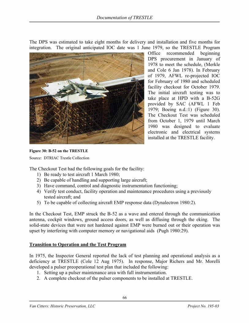
Documentation of TRESTLE
66
Van Citters: Historic Preservation, LLC Project No. 195-03
The DPS was estimated to take eight months for delivery and installation and five months for integration. The original anticipated IOC date was 1 June 1979, so the TRESTLE Program
Office recommended beginning DPS procurement in January of 1978 to meet the schedule, (Merkle and Cole 6 Jan 1978). In February of 1979, AFWL re-projected IOC for February of 1980 and scheduled facility checkout for October 1979. The initial aircraft testing was to take place at HPD with a B-52G provided by SAC (AFWL 1 Feb 1979; Boeing n.d.:1) (Figure 30). The Checkout Test was scheduled from October 1, 1979 until March 1980 was designed to evaluate electronic and electrical systems installed at the TRESTLE facility.
Figure 30: B-52 on the TRESTLE
Source: DTRIAC Trestle Collection The Checkout Test had the following goals for the facility:
1) Be ready to test aircraft 1 March 1980; 2) Be capable of handling and supporting large aircraft; 3) Have command, control and diagnostic instrumentation functioning; 4) Verify test conduct, facility operation and maintenance procedures using a previously
tested aircraft; and 5) To be capable of collecting aircraft EMP response data (Dynalectron 1980:2).
In the Checkout Test, EMP struck the B-52 as a wave and entered through the communication antenna, cockpit windows, ground access doors, as well as diffusing through the eking. The solid-state devices that were not hardened against EMP were burned out or their operation was upset by interfering with computer memory or navigational aids (Pugh 1980:29).
Transition to Operation and the Test Program In 1975, the Inspector General reported the lack of test planning and operational analysis as a deficiency at TRESTLE (Cole 12 Aug 1975). In response, Major Richers and Mr. Morelli developed a pulser preoperational test plan that included the following:
1. Setting up a pulser maintenance area with full instrumentation. 2. A complete checkout of the pulser components to be installed at TRESTLE.
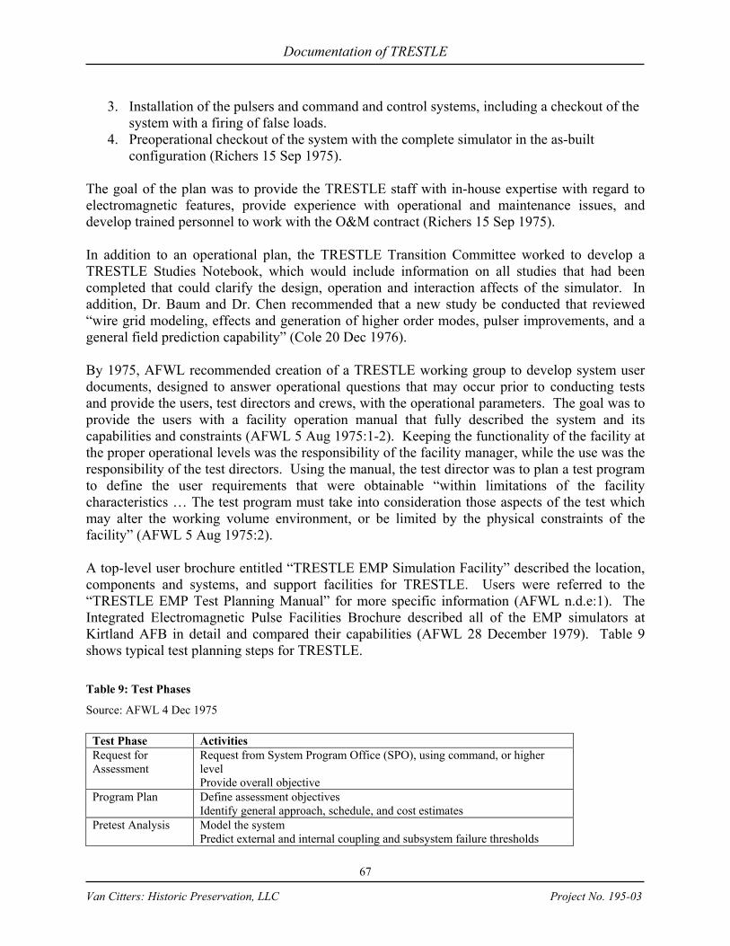
Documentation of TRESTLE
67
Van Citters: Historic Preservation, LLC Project No. 195-03
3. Installation of the pulsers and command and control systems, including a checkout of the system with a firing of false loads.
4. Preoperational checkout of the system with the complete simulator in the as-built configuration (Richers 15 Sep 1975).
The goal of the plan was to provide the TRESTLE staff with in-house expertise with regard to electromagnetic features, provide experience with operational and maintenance issues, and develop trained personnel to work with the O&M contract (Richers 15 Sep 1975). In addition to an operational plan, the TRESTLE Transition Committee worked to develop a TRESTLE Studies Notebook, which would include information on all studies that had been completed that could clarify the design, operation and interaction affects of the simulator. In addition, Dr. Baum and Dr. Chen recommended that a new study be conducted that reviewed “wire grid modeling, effects and generation of higher order modes, pulser improvements, and a general field prediction capability” (Cole 20 Dec 1976). By 1975, AFWL recommended creation of a TRESTLE working group to develop system user documents, designed to answer operational questions that may occur prior to conducting tests and provide the users, test directors and crews, with the operational parameters. The goal was to provide the users with a facility operation manual that fully described the system and its capabilities and constraints (AFWL 5 Aug 1975:1-2). Keeping the functionality of the facility at the proper operational levels was the responsibility of the facility manager, while the use was the responsibility of the test directors. Using the manual, the test director was to plan a test program to define the user requirements that were obtainable “within limitations of the facility characteristics … The test program must take into consideration those aspects of the test which may alter the working volume environment, or be limited by the physical constraints of the facility” (AFWL 5 Aug 1975:2). A top-level user brochure entitled “TRESTLE EMP Simulation Facility” described the location, components and systems, and support facilities for TRESTLE. Users were referred to the “TRESTLE EMP Test Planning Manual” for more specific information (AFWL n.d.e:1). The Integrated Electromagnetic Pulse Facilities Brochure described all of the EMP simulators at Kirtland AFB in detail and compared their capabilities (AFWL 28 December 1979). Table 9 shows typical test planning steps for TRESTLE. Table 9: Test Phases
Source: AFWL 4 Dec 1975
Test Phase Activities Request for Assessment
Request from System Program Office (SPO), using command, or higher level Provide overall objective
Program Plan Define assessment objectives Identify general approach, schedule, and cost estimates
Pretest Analysis Model the system Predict external and internal coupling and subsystem failure thresholds

Documentation of TRESTLE
68
Van Citters: Historic Preservation, LLC Project No. 195-03
Test Phase Activities Test Planning Define test objectives
Design specific tests Prioritize tests Develop procedures
System Level Test Implement test plan
Subsystem Level Tests
Supplement and verify analytical predictions of subsystem failure thresholds
Integration Analysis
Pull together test results Determine system vulnerabilities
Program Organization for Operations and Testing Phase During 1979 and 1980, major emphasis was placed on transitioning TRESTLE to full operational status (O’Haver 1980:1). As TRESTLE was transitioning to an operational testing facility, Lt. Colonel Cole, TRESTLE Program Manager, requested heightened security (Cole 9 August 1977). To accommodate the “priority A” aircraft that were to be tested, the security fence was increased, mercury vapor lights and closed circuit television cameras were added, and a guardhouse was built for an increased guard force (4900th Air Base Wing c.1976:1–2). After IOC in February of 1980, the TRESTLE program was transferred to operational status under the control of the AFWL Nuclear Technology Office, with responsibility for program management and operation of the facility (Rich et al. n.d.:6-7). The TRESTLE Program Office was disestablished on 1 March 1980 (Merkle 4 Feb 1980). By August 4, 1980, TRESTLE was being managed by AFWL/NTM, the EMP Test Division, along with the other AFWL EMP simulator facilities (O’Haver 1980:2). AFWL developed safety procedures specific to the EMP facilities to ensure personnel would not be harmed by EMP during testing. Personnel were excluded from areas in which the exposure exceeded 100 kV/m for single pulse operation and areas in which exposure exceeded 300 volts/m for repetitive pulse operation. It had been shown that relatively low EMP field levels could cause cardiac pacemakers to function, although the effect was less severe during single pulse than repetitive pulse operations (Dowler 28 APR 1979:1). Prior to testing at TRESTLE, fuel was removed from the aircraft so it could be tested in “dry mode” and instrumentation was added in the aircraft service area. Fueling facilities, fire department support, and maintenance/logistical crew support were provided to support the effort (AFWL 1970:1-40–1-41). Once instrumentation was in place, the aircraft was moved onto the test stand with a towing tractor. Because the aircraft towing speed was limited to three mph, it took approximately an hour to move the aircraft into test position. The test stand contained a 100 ft by 100 ft matrix of tied-down points with 53 pairs of tiedown recesses. Each pair was equipped with a nylon strap capable of loadings up to 10,000 lbs (AFWL 22 July 1977:1-3).

Documentation of TRESTLE
69
Van Citters: Historic Preservation, LLC Project No. 195-03
Gaseous nitrogen and air conditioning were available on the test stand and at the service area to the north. This was required to keep the aircraft cool during the testing process. Fire protection was also installed at TRESTLE prior to IOC to reduce risk to aircraft and personnel (USAF 23 August 1978) (Figure 31). The minimum quantity of water for the system was 8,000 gallons per minute for a period of one hour, which required a storage tank of 500,000 gallons and a pumping system with pressure of 75 – 100 psi (Cole 15 Oct 1976).
Figure 31: A Schematic Design for the Fire Protection System
Source: Cole 15 Oct 1976 Once the aircraft was on the test stand, EMP simulation at TRESTLE was produced by rapidly switching a high voltage, high-energy pulse from a source (the pulsers) onto an antenna (the transmission lines). A warning sounded and flashing lights were set into motion prior to the initiation of the test, the Marx generators were charged for two minutes, and on command, the pulser discharged into the transmission line. The antenna then radiated an electromagnetic wave in a similar manner to a radio wave. The pulses created during a test were of nanosecond duration and although there were millions of volts, the pulse did not have a physical characteristic. There were no flashes, blasts or shocks, but there was a small sound due to the discharge from the main output switches, which that was similar to the sound of a muffled 22-caliber rifle; the greatest effect that could be noticed was a “click” on an audio circuit (USAF 1973:3; Cole July 1976:5,10). Aircraft test programs at TRESTLE ranged from three to six months, with a standard five-day workweek and second shifts as required. During times when no testing was taking place, there were 25 administrative crewmembers at the TRESTLE. Approximately 50 additional personnel arrived on site to conduct the tests and worked from trailers during the test. To begin a test, the test object, or aircraft, was instrumented at specified locations to monitor the electrical response. It was then towed along the ramp to the test stand (working volume) and was positioned in the orientation required for the test. Test orientations included moving the pulse across the aircraft
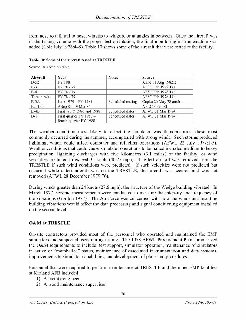
Documentation of TRESTLE
70
Van Citters: Historic Preservation, LLC Project No. 195-03
from nose to tail, tail to nose, wingtip to wingtip, or at angles in between. Once the aircraft was in the testing volume with the proper test orientation, the final monitoring instrumentation was added (Cole July 1976:4–5). Table 10 shows some of the aircraft that were tested at the facility. Table 10: Some of the aircraft tested at TRESTLE
Source: as noted on table
Aircraft Year Notes Source B-52 FY 1981 Kline 11 Aug 1982:2 E-3 FY 78 - 79 AFSC Feb 1978:14a E-4 FY 78 - 79 AFSC Feb 1978:14a Tomahawk FY 78 - 79 AFSC Feb 1978:14a E-3A June 1979 – FY 1981 Scheduled testing Cupka 26 May 78:attch 1 EC-135 9 Sep 83 – 9 Mar 84 AFLC 3 Feb 81 E-4B First ¼ FY 1986 and 1988 Scheduled dates AFWL 31 Mar 1984 B-1 First quarter FY 1987 –
fourth quarter FY 1988 Scheduled dates AFWL 31 Mar 1984
The weather condition most likely to affect the simulator was thunderstorms; these most commonly occurred during the summer, accompanied with strong winds. Such storms produced lightning, which could affect computer and refueling operations (AFWL 22 July 1977:1-5). Weather conditions that could cause simulator operations to be halted included medium to heavy precipitation; lightning discharges with five kilometers (3.1 miles) of the facility; or wind velocities predicted to exceed 35 knots (40.25 mph). The test aircraft was removed from the TRESTLE if such wind conditions were predicted. If such velocities were not predicted but occurred while a test aircraft was on the TRESTLE, the aircraft was secured and was not removed (AFWL 28 December 1979:76). During winds greater than 24 knots (27.6 mph), the structure of the Wedge building vibrated. In March 1977, seismic measurements were conducted to measure the intensity and frequency of the vibrations (Gordon 1977). The Air Force was concerned with how the winds and resulting building vibrations would affect the data processing and signal conditioning equipment installed on the second level.
O&M at TRESTLE On-site contractors provided most of the personnel who operated and maintained the EMP simulators and supported users during testing. The 1978 AFWL Procurement Plan summarized the O&M requirements to include: test support, simulator operation, maintenance of simulators in active or “mothballed” status, maintenance of associated instrumentation and data systems, improvements to simulator capabilities, and development of plans and procedures. Personnel that were required to perform maintenance at TRESTLE and the other EMP facilities at Kirtland AFB included:
1) A facility engineer 2) A wood maintenance supervisor
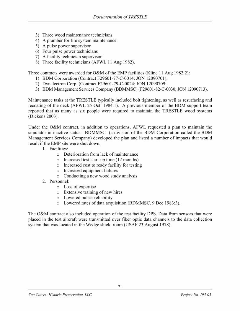
Documentation of TRESTLE
71
Van Citters: Historic Preservation, LLC Project No. 195-03
3) Three wood maintenance technicians 4) A plumber for fire system maintenance 5) A pulse power supervisor 6) Four pulse power technicians 7) A facility technician supervisor 8) Three facility technicians (AFWL 11 Aug 1982).
Three contracts were awarded for O&M of the EMP facilities (Kline 11 Aug 1982:2):
1) BDM Corporation (Contract F29601-77-C-0014; JON 12090701); 2) Dynalectron Corp. (Contract F29601-79-C-0024; JON 12090709; 3) BDM Management Services Company (BDMMSC) (F29601-82-C-0030; JON 12090713).
Maintenance tasks at the TRESTLE typically included bolt tightening, as well as resurfacing and recoating of the deck (AFWL 25 Oct. 1984:1). A previous member of the BDM support team reported that as many as six people were required to maintain the TRESTLE wood systems (Dickens 2003). Under the O&M contract, in addition to operations, AFWL requested a plan to maintain the simulator in inactive status. BDMMSC (a division of the BDM Corporation called the BDM Management Services Company) developed the plan and listed a number of impacts that would result if the EMP site were shut down.
1. Facilities: o Deterioration from lack of maintenance o Increased test start-up time (12 months) o Increased cost to ready facility for testing o Increased equipment failures o Conducting a new wood study analysis
2. Personnel: o Loss of expertise o Extensive training of new hires o Lowered pulser reliability o Lowered rates of data acquisition (BDMMSC. 9 Dec 1983:3).
The O&M contract also included operation of the test facility DPS. Data from sensors that were placed in the test aircraft were transmitted over fiber optic data channels to the data collection system that was located in the Wedge shield room (USAF 23 August 1978).
Documentation of TRESTLE
72
Van Citters: Historic Preservation, LLC Project No. 195-03
Figure 32: TRESTLE data system block diagram
Source: AFWL 1979 (revised 81) End of the Cold War and End of Simulator Operations Presidents Johnson, Nixon, Ford and Carter presided over a series of arms treaties including the Strategic Arms Limitation Treaties, the Vladisvostok Accords, and the ABM Protocol. The 1970s and 1980s were a period of détente that resulted in dramatically lowering weapons development and deployment activities. We will add more to summary once we gain more information. Our primary questions about TRESTLE are below. If you are reviewing this document and know the answer, please let us know. In our text, have we listed all the aircraft that were tested at TRESTLE? When was the last test? Why did testing stop? Were the tests effective? How were data gaps from TRESTLE filled in? Was the C-5 ever tested at TRESTLE? Is there a list of tests that were conducted at TRESTLE? Did TRESTLE contribute to survivability and adequately hardening aircraft?
Documentation of TRESTLE
73
Van Citters: Historic Preservation, LLC Project No. 195-03
What is D&F? What is the stored energy in the 5 MV pulsers? Were radiating switches installed to deal with the asynchronism?
If you have any other general comments about the document or other information that the document should include, please provide that information as well.

Documentation of TRESTLE
74
Van Citters: Historic Preservation, LLC Project No. 195-03
GLOSSARY corona discharge
An electrical discharge characterized by a corona (faint glow) and occurring when one of two electrodes in a gas has a shape causing the electric field at its surface to be significantly greater than that between the electrodes.
dielectric
Pertaining to a substance that has a zero or near zero electrical conductivity. electromagnetic pulse
1.Radiation made up of oscillating electric and magnetic fields and propagated with the speed of light, which results from a nuclear explosion caused by Compton-recoil electrons and photoelectrons from photons scattered in the materials of the nuclear device. The resulting electric and magnetic fields may couple with electrical/electronic systems to produce damaging current and voltage surges. 2. A broadband, high-intensity, short-duration burst of electromagnetic energy.
figures of merit The design and performance parameters used to develop EMP simulators.
gamma rays
Electromagnetic radiation of high photon energy originating in atomic nuclei and accompanying many nuclear reactions (e.g., fission, radioactivity, and neutron capture). Physically, gamma rays are identical with x rays of high energy, the only essential difference being x rays do not originate from atomic nuclei, but are produced in other ways (e.g., by slowing down (fast) electrons of high energy). See x rays.
hardening
Design allowances made to prevent or ameliorate the effects of gamma or high-energy neutron radiation or bombardment.
high altitude burst
A nuclear explosion produced above the atmosphere, i.e., above about 120 kilometers. high altitude electromagnetic pulse
An electromagnetic pulse produced at an altitude effectively above the sensible atmosphere, i.e., above about 120 kilometers.
Joule
Unit of energy or work, equal to the work done when the application point of a one Newton force moves one meter in the direction of application.
kilojoule One thousand joules.

Documentation of TRESTLE
75
Van Citters: Historic Preservation, LLC Project No. 195-03
kilovolt
One thousand volts. megahertz
A unit of frequency equal to one million electrical cycles per second. The speed of the microprocessor in a computer is traditionally measured in megahertz. For example, a computer that runs at 250 MHz is able to execute 250 million cycles per second. All software requires millions of cycles for each separate task it completes. So, the faster the microprocessor (or, the higher the MHz), the faster the software on your computer will run.
megavolt
One million volts. nanoseconds One billionth of a second. rise time
The time required for the output of a system to change from a specified small percentage (usually 5 or 10 percent) of its steady-state increment to a specified large percentage (usually 90 or 95 percent).
split ring A structural connector that collects the load from one member and transfers it to another. The ring is split so that is can be fitted into a circular groove, slightly larger than the ring, on the meeting face of each structural timber member. The split opens when the ring is sprung into the groove and this gap in the ring may open or close as the timber shrinks and swells.
torus or toroid
A doughnut-shaped geometric surface generated by rotating a circle about a line in the same plane as the circle but not intersecting it.
volt The unit of electromotive force and electric potential difference equal to the difference between two points in a circuit carrying one ampere of current and dissipating one watt of power.
X Rays
Electromagnetic radiations of high energy having wavelengths shorter than those in the ultraviolet region, i.e., less than 10 cm or 100 Angstroms. Materials at very high temperatures (millions of degrees) emit such radiations; they are then called thermal x rays.
Documentation of TRESTLE
76
Van Citters: Historic Preservation, LLC Project No. 195-03
REFERENCES CITED
4900th Air Base Wing. Circa 1976. “Memo regarding clandestine vulnerability at TRESTLE.” DTRAIC TRESTLE Collection, Box 7A, Folder “Security.”
Air Force Audit Agency. 1977. “Report of Audit 0935 — , Review of the TRESTLE Program
Acquisition, Air Force Weapons Laboratory, Kirtland Air Force Base, New Mexico.” 20 January. DTRIAC TRESTLE Collection, Box 4B, Folder “18 FO2 Air Force Audit Agency, Review of the TRESTLE Program Acquisition Audit 0935.”
Air Force Logistics Command (AFLC). 1981. Memorandum on Nuclear Effects Testing, PMD
R-P4003(8), 7 July. DTRIAC TRESTLE Collection, Box 5A. Air Force Systems Command (AFSC). 16 August 1974. Teletype from AFSC Andrews AFB,
Maryland to Kirtland AFB, New Mexico. DTRIAC TRESTLE Collection, Box 5A, unnamed folder.
———. 23 August 1974. Teletype from AFSC Andrews AFB, Maryland to Kirtland AFB, New Mexico. DTRIAC TRESTLE Collection, Box 5A, unnamed folder.
———. 1978. Justification for Authority to Negotiate. Section 13.5.1.1, Sole Source Justification, 14-15 February. DTRIAC TRESTLE Collection, Box 5A, untitled folder.
Air Force Weapons Laboratory (AFWL) n.d. (a) Handwritten chart of phases. DTRIAC
TRESTLE Collection, Box 1B, IG PMAT binder. ———. n.d. (b) Memo to Lt. Col. Hartman “TRESTLE Cost Estimates.” DTRIAC TRESTLE
Collection, Box 4B, Folder 18-B01. ———. n.d. (c) “TRESTLE I: The Torturous Path of TRESTLE Evolution.” DTRIAC
TRESTLE Collection, Box 7B, no folder. ———. n.d. (d) “Evaluation Factors for Award.” DTRIAC TRESTLE Collection, Box 6A,
Folder “1209 (Section F) Supl Folder 02, TRESTLE Program Office Correspondence (Jul – Sep 1975).”
———. n.d. (e) TRESTLE Wood Systems Outline. DTRIAC TRESTLE Collection, Box 3A, Folder “O&M Manuals AO-30.” CHECK AUTHOR AND DATE
———. n.d. (f) TRESTLE EMP Simulator Facility. User Brochure. DTRIAC TRESTLE Collection, Box 6A, Folder “1209 (Section F) Supl Folder EMP Facility Info.”
———. 1970. EMP High Altitude Simulation (HAS) Technology Reports: Bounded Wave Simulators (TRESTLE). September 1970. DTRIAC TRESTLE Collection, Box 9B.
———. 1971. Interim TRESTLE Report. DTRIAC TRESTLE Collection, Box 5B, Folder “1209 (Section C) Supl Folder 08, Interim TRESTLE Report, 24 Aug 71.”
———. 8 March 1973. TRESTLE Questions and Answers (As per Air Staff/AFSC request of 8 March 1973). DTRIAC TRESTLE Collection Box 3B, Folder “WL84-45CAD, NASTRAN and TRESTLE.”
———. 9 May 1974. Memo to Wood Products Office regarding “Support Agreement, Z6-DSA720-0001-3, Procurement of Structural Timber for TRESTLE.”

Documentation of TRESTLE
77
Van Citters: Historic Preservation, LLC Project No. 195-03
———. 30 June 1974. FY 74 4th Quarter Report. DTRIAC TRESTLE Collection, Box 5B, Folder 1209 (Section F) Supl Folder 02, TRESTLE Program Office Correspondence (Apr-Jun 1974).
———. 1 April 1975. Research and Development Management Report. DTRIAC TRESTLE Collection, Box 6A, Folder “1209 (Section F) Supl Folder, TRESTLE Program Office Correspondence (Apr – Jun 1975).
———. 1 July 1975. Recommendation for Decoration for Billy F. Lucas, Captain. DTRIAC TRESTLE Collection, Box 6A, Folder “1209 (Section F) Supl Folder 02, TRESTLE Program Office Correspondence (Jul-Sep 1975).
———. 1 August 1975. Specification No. ES7811600. Test Stand and Ramp Subsystem. DTRIAC TRESTLE Collection, Box 3A, Folder “O&M Manuals AO-30.” CHECK AUTHOR
———. 5 August 1975. Memo for Record: TRESTLE System Working Group. DTRIAC TRESTLE Collection, Box 6A, Folder “1209 (Section F) Supl Folder 02 TRESTLE Program Office Correspondence (Jul-Sep 1975).
———. 14 August 1975. Pulser Preoperational Test. DTRIAC TRESTLE Collection, Box 6A, Folder “1209 (Section F) Supl Folder 02, TRESTLE Program Office Correspondence (Jul-Sep 1975).
———. 31 October 1975. Project Order to U.S. Army Waterways Experiment Station. DTRIAC TRESTLE Collection, Box 6A, Folder “1209 (Section F) Supl Folder 02, TRESTLE Program Office Correspondence (Jul-Sep 1975).”
———. 4 December 1975. Outline of EMP Assessment Flow for Aircraft. DTRIAC TRESTLE Collection Box 7A, Folder “Testing.”
———. 8 July 1976. Program Management Plan for Electromagnetic Pulse (EMP) Test Facilities Program Element 64747F/Project 1209. DTRIAC TRESTLE Collection, Box 3B, Folder “Program Plans.”
———. 17, 18 January 1977. Trip Report of Visit to the U.S. Forest Products Laboratory (FPL). DTRIAC TRESTLE Collection, Box 3B, Folder “ADM-6 Trip Reports 1979.”
———. 22 July 1977. User’s Brochure “Newsletter.” DTRIAC TRESTLE Collection, Box 3B, Folder “Special Studies.”
———. September 1977. Air Force Weapons Laboratory Advance Procurement Plan for the Electromagnetic Pulse Test Facilities. DTRIAC TRESTLE Collection, Box 1B, APP Correspondence.
———. 1 Feb 1979. Memo. “TRESTLE Input for Status Report on Previous 1209 Program Direction and In-depth Review of New Program Direction.” DTRIAC TRESTLE Collection, Box 5A, unnamed folder.
———. 28 December 1979 (revised 1-2 March 1981). Integrated Electromagnetic Pulse Facilities Brochure. DTRIAC TRESTLE, Box 6A, Folder 1209 (Section F) Supl Folder, EMP Facility Information/Descriptions.
———. February 1980. Joint Message Form. Subject: TRESTLE IOC. DTRIAC TRESTLE Collection, Box 3B.
———. 15 April 1981. Review of FY81 Project 1209 Program Direction. DTRIAC TRESTLE Collection, Box 5A.
———. March 1982. Five Year Program Plan for the AFWL Aeronautical Systems Applied EMP Technology Program. DTRIAC TRESTLE Collection, Box 2B, Folder 40.
Documentation of TRESTLE
78
Van Citters: Historic Preservation, LLC Project No. 195-03
———. 11 August 1982. EMP Simulator Operations and Maintenance. DTRIAC TRESTLE Collection, Box 2A, Folder 1.
———. 1983-1984. History of the Air Force Weapons Laboratory for 1 October 1983 – 30 September 1984. Air Force Research Laboratory Phillips Research Site Historical Information Office.
———. 31 March 1984. Program Schedule (AFSC Form 103). DTRIAC TRESTLE Collection, Box 2A, Folder 13.
———. 25 October 1984. Research and Development Management Report. 4th Quarter FY 84 R&D Report. DTRIAC TRESTLE Collection, Box 2A, Folder 2.
Air Force Special Weapons Center (AFSWC). September 1971. Research and Development
Sources Sought, Synopsis Number 134-71. DTRIAC TRESTLE Collection, Box 7A, Folder “Personnel Information.”
Author unknown. n.d. TRESTLE Structural Load Test. DTRIAC TRESTLE Collection, Box 3A. Batzel, Roger. 7 November 1975. Letter to Dr. Soloman J. Buchsbaum, Chairman of the Defense
Science Board responding to questions from the Strategic and Space Systems, DDR&E. DTRIAC TRESTLE Collection, Box 8A, Folder “VTF TRESTLE.”
Baum, Carl E., Captain. 1969. “Some Considerations Concerning a Horizontally Polarized
Transmission-Line Simulator.” Sensor and Simulation Notes, Note 82 (12 April 1969). Air Force Research Laboratory, Directed Energy Directorate, Dr. Carl Baum’s files.
———. 1974. ATLAS MEMOS, Memo 10: Electromagnetic Considerations for Pulser Design. 6 April 1974. Air Force Research Laboratory, Directed Energy Directorate, Dr. Carl Baum’s files.
Baum, C.E., D. F. Higgins, D. V. Giri. 1976. ATLAS MEMOS, Memo 18, Pulser Test Results
and Preliminary Estimation of Transient Electric Field Waveforms in ATLAS I (7 October 1976). Air Force Research Laboratory, Directed Energy Directorate, Dr. Carl Baum’s files.
Baum, C. E., D. V. Giri, K. C. Chen. 1977. ATLAS MEMOS, Memo 22, An Overview of EM
Considerations of ATLAS in the Context of Current and Future Efforts (5 January 1977). Air Force Research Laboratory, Directed Energy Directorate, Dr. Carl Baum’s files.
Baum, Carl E. 1978a. “EMP Simulators for Various Types of Nuclear EMP Environments: An
Interim Categorization.” IEEE Transactions on Antennas and Propagation, January. Vol. AP-26, No. 1.
Baum, C. E. 1978b. ATLAS Memos, Memo 24, Field Mapping for ATLAS I (29 January 1978).
Air Force Research Laboratory, Directed Energy Directorate, Dr. Carl Baum’s files. BDM Management Services Company (BDMMSC). 9 December 83. AFWL EMP Facilities
O&M. DTRIAC TRESTLE Collection, Box 2A, Folder 25.
Documentation of TRESTLE
79
Van Citters: Historic Preservation, LLC Project No. 195-03
Boeing Wichita Company. n.d. TRESTLE Piggyback Test Plan. DTRIAC TRESTLE Collection,
Box 2B, Folder 42. Bracher, Robert B., Sergeant. 1974. Memo for Record: Allowable Stresses for Split-Ring
Connectors Used in Joint Design of TRESTLE Glu Lam Structures, 29 March. DTRIAC TRESTLE Collection, Box 5b, Folder “1209 (Section F) Supl Folder, TRESTLE Program Office Correspondence (Jan-Mar 1974).
Buchsbaum, Solomon J. 1976. Memo from the Chairman of the Defense Science Board to the
Secretary of Defense through the Director of Defense Research and Engineering regarding the Defense Science Board Systems Vulnerability Task Force final report on large-scale EMP simulators (5 May 1976). DTRIAC TRESTLE Collection, Box 5B, untitled folder.
Castillo, J. Phillip. 8 April 1974. Memo for Record. “Evaluation of TRESTLE Program Status
and Major Operations.” DTRIAC TRESTLE Collection. Box 5A, Folder “Project 1209 EMP simulation and Testing.”
Civil Engineering-ASCE. April 1977. “Wooden trestle built to simulate nuclear warfare
conditions.” DTRIAC TRESTLE Collection, Box 6A, Folder “1209 (Section F) 03 Publicity & News Releases.
Cole, Donald C., Lt. Colonel. 31 July 1974. Management Assessment Report. DTRAIC
TRESTLE Collection. Box 6A, Folder “1209 (Section F) Supl folder, TRESTLE Program Office Correspondence (Jul – Sep 1974).”
———. 6 August 1974. Memo. “Quality Inspection/Surveillance Plan, MDAC Ltr A78-DWC-0819.” Box 6A, Folder “1209 (Section F) Supl folder, TRESTLE Program Office Correspondence (Jul – Sep 1974).”
———. 18 August 1974. Memo. “TRESTLE Contract F29601-73-C-0090, TRESTLE Program Plans, Vol II, Configuration Management Plan, CCDRL Item A011, MDC G5063, 21 Dec 73.” Box 6A, Folder “1209 (Section F) Supl folder, TRESTLE Program Office Correspondence (Jul – Sep 1974).”
———. 28 August 1974. Memo. “C-5A Turning Study (T-RODs A78-0732, A78-0733, and A78-0734).” DTRIAC, TRESTLE Collection, Box 5B,, folder “1209 (Section F) Supl Folder TRESTLE Program Office Correspondence (Jul – Sep 1974).”
———. 30 August 1974. Memorandum “Results of the TRESTLE Caisson Meeting held on 28 Aug 74.” DTRIAC TRESTLE Collection, Box 6A, Folder “1209 (Section F) Supl Folder, TRESTLE Program Office Correspondence (Jul-Sep 1974).
———. 10 Sep 1974. Memo from AFWL to AFSC. “TRESTLE Program Phase Down.” Box 5B, Folder “1209 (Section F) Supl Folder 02, TRESTLE Program Office Correspondence (Jul – Sep 1974).”
———. 26 Sep 1974. Memo. “Quality Inspection/Surveillance Plan, MDAC Ltr A78-DWC-0819.” Box 6A, Folder “1209 (Section F) Supl folder, TRESTLE Program Office Correspondence (Jul – Sep 1974).”
Documentation of TRESTLE
80
Van Citters: Historic Preservation, LLC Project No. 195-03
———. 25 Apr 1975. Memo. “Engineering Data for Plywood gusset Materials.” Box 6A, Folder “1209 (Section F) Supl folder, TRESTLE Program Office Correspondence (Apr – Jun 1974).”
———. 13 June 1975. Weekly Activities Report. DTRIAC TRESTLE Collection, Box 6A, Folder “1209 (Section F) Supl Folder, TRESTLE Program Office Correspondence (Apr-Jun 1975).
———. 16 Jun 1975. Memo. “Wood System Design – Gusset Plates.” Box 6A, Folder “1209 (Section F) Supl folder, TRESTLE Program Office Correspondence (Apr – Jun 1974).”
———. 20 June 1975. Memorandum, TRESTLE Ramp and Pulser Support Stands Synopsis. DTRIAC TRESTLE Collection, Box 6A, Folder “1209 (Section F) Supl Folder 02, TRESTLE Program Office Correspondence (Apr-Jun 1975).
———. 22 Jul 1975. Memo. “TRESTLE Aircraft Tiedown Recommendations.” DTRIAC TRESTLE Collection, Box 6A, Folder “1209 (Section F) Supl folder, TRESTLE Program Office Correspondence (Jul – Sep 1975).”
———. 12 Aug 1975. Memo. “TRESTLE Operational Planning.” Box 6A, Folder “1209 (Section F) Supl folder, TRESTLE Program Office Correspondence (Apr – Jun 1974).”
———. 11 Dec 1975. Memo. “TRESTLE PMAT.” DTRIAC TRESTLE Collection, Box 6A, Folder “1209 (Section E) Supl Folder, TRESTLE Program Office Correspondence (Oct – Dec 1975).”
———. July 1976. “Environmental Assessment, Kirtland Air Force Base, New Mexico, Air Force Systems Command, Program Element 64747F, Project 1209 TRESTLE Electromagnetic Pulse Simulator.” DTRIAC TRESTLE box 1B, IG PMAT binder.
———. 15 October 1976. Memorandum, Water Main for TRESTLE Fire Protection System. DTRIAC TRESTLE Collection, Box 6A, Folder “1209 (Section F) Supl Folder 02, TRESTLE Program Office Correspondence (Oct-Dec 1976).
———. 12 November 1976. Memorandum, TRESTLE Facility Access. DTRIAC TRESTLE Collection, Box 1B, APP Correspondence.
———. 20 December 1976. Memo. “Identification for TRESTLE Related Studies.” DTRIAC TRESTLE Collection, Box 6A, Folder “1209 (Section F) Supl Folder 02, TRESTLE Program Office Correspondence (Oct – Dec 1976).”
———. 15 July 1977. Letter to Major Jedlicka regarding AFWL Research and Technology Plan. DTRIAC TRESTLE Collection Box 1B, APP Correspondence.
———. 9 August 1977. Letter to AFWL, AFCMD & 1606 Air Base Wing Security Police regarding TRESTLE Security requirements. DTRIAC TRESTLE Collection Box 7A, Folder Security.
———. 29 November 1977. Memo. “TRESTLE Program Office Nov 77 Activity Report.” DTRIAC TRESTLE Collection, Box 1B, TPP Correspondence.
Cupka, Albert G., Lt. Colonel. 26 May 1978. E-3A EMP TRESTLE Test Estimates. DTRIAC
TRESTLE Collection, Box 2B, Folder 42. Dana, Tom. 2002. Interview with Karen Van Citters and Kristen Bisson.

Documentation of TRESTLE
81
Van Citters: Historic Preservation, LLC Project No. 195-03
Defense Science Board. July 1975. “Report on Large-Scale EMP Simulators.” Systems Vulnerability Task Force, Office of the Director of Defense Research and Engineering, Washington, D.C. DTRIAC TRESTLE Collection, Box 5B, untitled folder.
Defense Threat Reduction Agency. 2001. “Defense’s Nuclear Agency: History of AFSWP to
DSWA 1947-1997.” Washington, D.C. DTRIAC Collection. Dickens, John J. 2003. Informal conversation with Debbie Butcher, 18 September 2003. Dowler, Donald A., Colonel. 28 April 1979. EMP Facility Operating Procedures. EL Instruction
127-2. DRTIAC TRESTLE Collection Box 9B. Duffner, Robert W., Ph.D., and Daniel F. Harrington, Ph.D. 1985. “History of the Air Force
Weapons Laboratory for 1 October 1983 – 30 September 1984, Volume I.” Duffner, Robert W., Ph.D., Ward Alan Minge, Ph.D., and Vernon L. Briley, S.Sergeant. 1978.
“History of the Air Force Weapons Laboratory for 1 January – 31 December 71, Volume I: Narrative.” Albuquerque: Air Force Weapons Laboratory History Office.
Duffner, Robert W., Ph.D., Ward Alan Minge, Ph.D., Vernon L. Briley, S.Sergeant., and Terry
Fletcher. 1972. “History of the Air Force Weapons Laboratory for 1 January – 31 December 72, Volume I: Narrative.” Albuquerque: Air Force Weapons Laboratory History Office.
Dynalectron Corporation. 17 February 1980. TRESTLE Checkout Test Final Report (draft).
DTRIAC TRESTLE Collection, Box 4B. EG&G, Albuquerque Division, Services and Systems Group. 1971. TRESTLE Design Study,
Volume I Final Report (Technical), 15 November 1971. DTRIAC TRESTLE Collection, Box 9B.
Federation of American Scientists. n.d. Special Weapons Primer. <www.fas.org/nuke/intro/nuke/emp.htm> Federation of American Scientists. 2003 <www.fas.org> Focus. 14 June 1974. “Laminated Giants.” From William Prather clipping file notebook. Fostiak, Oleh E. Captain. 21 August 1974a. Memo for Lt. Colonel Cole. “TRESTLE
Configuration Control.” DTRIAC TRESTLE Collection, Box 6A, Folder, “1209 (Section F) Supl Folder, TRESTLE Program Office Correspondence (Jul – Sep 1974).”
———. 21 August 1974b. Memo for Record. “Configuration Management Plan (DCEs).” DTRIAC TRESTLE Collection, Box 6A, Folder, “1209 (Section F) Supl Folder, TRESTLE Program Office Correspondence (Jul – Sep 1974).”

Documentation of TRESTLE
82
Van Citters: Historic Preservation, LLC Project No. 195-03
Fostiak, Oleh E. Captain and Major Glen A. Thompson. 16 November 1976. Memo for Record. “Contractor evaluation – Allen M. Campbell, Oct 76.” DTRIAC TRESTLE Collection, Box 6A, Folder, “1209 (Section F) Supl Folder, TRESTLE Program Office Correspondence (Oct – Dec 1974).”
Freyer, Gustav J., Colonel. November 1975. Memorandum. DTRIAC TRESTLE Collection,
Box 6A, Folder 1209 (Section E) Supl Folder, TRESTLE Program Correspondence (Oct – Dec 1975).
———. 8 December 1975. Memo. “Accelerated TRESTLE Program.” DTRIAC TRESTLE Collection, Box 6A, Folder “1209 (Section E) Supl folder, TRESTLE Program Correspondence (Oct – Dec 1975).”
Futch, Walter L., Major. 11 Jan 1974. Memo “GFE Wood for TRESTLE Platforms.” Futch, Walter L., Major and Swan, John W., Colonel. 28 Feb 74. Management Assessment
Report. DTRIAC TRESTLE Collection, Box 5B, untitled folder. ———. 6 Mar 74. Management Assessment Report. DTRIAC TRESTLE Collection, Box 5B,
untitled folder. ———. 26 Mar 74. Management Assessment Report. DTRIAC TRESTLE Collection, Box 5B,
untitled folder. Futch, Walter L., Major. 1 April 1974. Memorandum “Additional Core Borings.” DTRIAC
TRESTLE Box 2B, Folder 45. ———. 8 April 1974. Memorandum, Pulser Status. DTRIAC TRESTLE Collection, Box 5B,
Folder “1209 (Section F) Supl Folder 02, TRESTLE Program Office Correspondence (Apr-Jun 1974).
———. 24 April 1974. Memorandum, Pulser Status. DTRIAC TRESTLE Collection, Box 5B, Folder “1209 (Section F) Supl Folder 02, TRESTLE Program Office Correspondence (Apr-Jun 1974).
———. 3 May 1974. Memo regarding “Contract F29601-73-C-0090, A015 – Horizontal Simulator Test Stand and Ramp Subsystem Design Analysis Report.”
Gaither, Steve. 1997. “Looking between Trinity and the Wall: Army Materiel Command Cold
War Material Culture within the Continental United States.” Plano, Texas: Geo-Marine. Giles, J.C. 2000. “IEC Project 61000-4-32, HEMP Simulator Compendium, Draft.” Los
Alamos: Los Alamos National Laboratory Nonproliferation and International Security Division.
Giri, D. V. 28 September 1979. ATLAS MEMOS, Memo 26, A Study of the Monocone Switch
Used with Marx Pulsers. Air Force Research Laboratory, Directed Energy Directorate, Dr. Carl Baum’s files.

Documentation of TRESTLE
83
Van Citters: Historic Preservation, LLC Project No. 195-03
Giri, D.V. and S.H. Sands. 1 February 1984. ATLAS Memos, Memo 32, Effects of Asynchronism between East and West Pulsers in ATLAS I facility. Air Force Research Laboratory, Directed Energy Directorate, Dr. Carl. Baum’s files.
Goetz, John L., Captain. 4 June 1974. Memo for Record, “Government Field Surveillance of
TRESTLE Construction.” DTRIAC TRESTLE Collection, Box 5B, Folder “1209 (Section F) Supl Folder 02, TRESTLE Program Office Correspondence (Apr – Jun 1974).”
Goetz, John L., Captain and John J. Ungvarsky. 21 May 1974. Trip report from observations of
MDAC structural tests. DTRIAC TRESTLE Collection. Box 5B, folder “1209 (Section F) Supl Folder 02, TRESTLE Program Office Correspondence (Apr – Jun 1974).”
Goetz, John L., Captain. 11 June 1975. Memo For Record, Preliminary Soil & Foundation
Investigation. DTRIAC TRESTLE Collection, Box 2B, Folder 45. ———. 12 June 1975. Memo For Record, My Memo, 11 June 75. DTRIAC TRESTLE
Collection, Box 2B, Folder 45. Gomez, Raymond V., Colonel. 9 Aug 1974. Letter to AFWL from Assistant Director of
Electronics & Weapons, Director of Science & Technology. Gordon, Donald C. 24 March 1977. Memo for Record, Seismic Measurement of Bldg 20797
(TRESTLE Wedge Building). DTRIAC TRESTLE Collection, Box 6A, Folder “1209 (Section F) Supl Folder, TRESTLE Program Office Correspondence (Jan-Mar 1977).
Graham, F. R. and D. V. Giri. 10 September 1979. ATLAS MEMOS, Memo 25, Review of
Electrical Characteristics of Marx Pulsers in ATLAS I. Air Force Research Laboratory, Directed Energy Directorate, Dr. Carl Baum’s files.
HQ USAF. 1973. “Program Management Directive R-P4003(1)/64747/1209.” 24 July 1973.
DTRIAC TRESTLE Collection, Box 5A, untitled folder. HQ USAF. 1980. “Program Management Directive for Nuclear Effects Simulation Test
Facilities.” 5 March 1980. DTRIAC TRESTLE Collection, Box 5A, unnamed folder. Harris, Cyril M. 2000. Dictionary of Architecture & Construction. McGraw Hill. New York. Higgins, Dan, Lt. 1971a. ATLAS MEMOS, Memo 4: Bounded Wave ATLAS I – Ground
Effects On a Horizontally Polarized Transmission Line – Parameter Study. 24 September 1971. Air Force Research Laboratory, Directed Energy Directorate, Dr. Carl Baum’s files.
———. 1971b. ATLAS MEMOS, Memo 5: Further EM Considerations Concerning the Height of the TRESTLE Platform. 1 November 1971. Air Force Research Laboratory, Directed Energy Directorate, Dr. Carl Baum’s files.

Documentation of TRESTLE
84
Van Citters: Historic Preservation, LLC Project No. 195-03
———. 1971c. ATLAS MEMOS, Memo 6: Ground Contouring Considerations. 31 December 1971. Air Force Research Laboratory, Directed Energy Directorate, Dr. Carl Baum’s files.
———. 1972. ATLAS MEMOS, Memo 7: Considerations of Property Terminating the Simulator Transmission Line. Air Force Research Laboratory, Directed Energy Directorate, Dr. Carl Baum’s files.
Jedlicka, Richard A., Major. 13 May 1974. Memo regarding trip to MDAC. “TRESTLE
Contract, No. F29601-73-C-0090, Program Control Study.” Jedlicka, Richard A., Major. 11 Feb 1976. Memo for Record. “Identification of DCAS
Administration Responsibilities for PR FY35927610017.” DTRIAC TRESTLE Collection, Box 1B, APP Correspondence.
———. 1977. “Air Force Weapons Laboratory Advance Procurement Plan for the Electromagnetic Pulse Test Facilities 64747F, September 1977.” DTRIAC TRESTLE Collection, Box 1B, APP Correspondence.
Kline, Brian E. 11 August 1982. EMP Simulator Operations and Maintenance. DTRIAC
TRESTLE Collection, Box 2A, Folder 1. Koppers. 1 November 1977. Marked up copy of news release with Harold Mendelsohn as the
contact. DTRIAC TRESTLE Collection, Box 9B, untitled folder. Larson, Oliver W., Lt. Colonel. 28 May 1974. Memorandum for DL, “TRESTLE
Electromagnetic Pulse Simulator.” DTRIAC TRESTLE Collection, Box 4B, Folder 18-B01.
———. 29 May 1974. Memorandum for DL, “TRESTLE Cost and Procurement Assistance Team.” DTRIAC TRESTLE Collection, Box 4B, Folder 18-B01.
Lewis, Karen, Katherine Roxlau, Lori Rhodes, Paul Boyer, and Joseph Murphey. 1995. “A
Systematic Study of Air Combat Command Cold War Material Culter, Volume I: Historic Context and Methodology for Assessment.” Fort Worth: United States Army Corps of Engineers.
Lizberg, Carl. 28 April 1974. “Huge wood beams made on Tideflats.” News Tribune. Tacoma.
DTRIAC TRESTLE Collection, Box 7A, Folder “Newspaper/Mag. Articles.” Maguire, Robert A., Jr., Captain. 18 Feb 1975. Memo “Establishment of TRESTLE Program
Office.” DTRAIC TRESTLE Collection, Box 7A, Folder “TRESTLE Organizational Charts.”
McDonnell Douglas. 1974. Wood Module Design Concept Recommendations, 12 February.
DTRIAC TRESTLE Collection, Box 2B, Folder 44.

Documentation of TRESTLE
85
Van Citters: Historic Preservation, LLC Project No. 195-03
Merewether, D. E., R. Fisher, J. Seeger, F. W. Smith, D Endsley, S. Cave, Electromagnetic applications EG&G. 30 January 1980. ATLAS MEMOS, Memo 27, Field Mapping Data for ATLAS I: Volume I.
Merkle, Douglas H., Lt. Colonel. 8 December 1976. Memo. “Award Fee Determination for
Contract F29601-76-C-0106 for Period 27 Jul to 27 Nov 76.” DTRIAC TRESTLE Collection, Box 6A, Folder “1209 (Section F) Supl Folder 02, TRESTLE Program Office Correspondence (Oct – Dec 1976).”
———. 6 Jan 1978. Joint Message Form. “State of TRESTLE DPS DAR.” DTRIAC TRESTLE Collection, Box 1B, TPP Correspondence.
———. 11 May 1978. Memo “Technology Management Reviews.” DTRIAC TRESTLE Collection. Box 1B, TPP Correspondence.
———. 12 January 1979. Letter of Appreciation for the Assistance of Mr. Jack Smith. DTRIAC TRESTLE Collection, Box 3B.
———. 4 February 1980. “Letter to AFWL regarding telephone control officer for TP.” DTRIAC TRESTLE Collection, Box 3B, no folder.
Morelli, Theodore J. 1974. Memo for Record, Demonstration of Pulser Performance, 19 June.
DTRIAC TRESTLE Collection, Box 5B, Folder “1209 (Section F) Suppl Folder 02, TRESTLE Program Office Correspondence (Apr-Jun 1974).
Name illegible. 27 June 1974. Memo to General Hudson about TRESTLE Management Actions.
DTRIAC, TRESTLE Collection. Box 4B, black notebook. O’Haver, Charles E., Deputy Chief, EMP Test Division. 4 August 1980. Status Report. DTRIAC
TRESTLE Collection. Plastics Museum. 2003. <http://www.plastics-museum.com/tech/companies/permali.htm> Portasik, John P., Colonel. 29 October 1973. “TRESTLE Electromagnetic Pulse (EMP) Facility
(Your Msg 121845Z Oct, AFSC Directive No 1209-3-74-5, and PMD R-P4003(1) 64747/1209, 24 July 73). DTRIAC TRESTLE Collection, Box 5A, untitled folder.
Prather, William D. 1974. ATLAS MEMOS, Memo 15: The Reflection of Electromagnetic
Waves from an Array of Electrically Small Metal Bolts and Rings. Air Force Research Laboratory, Directed Energy Directorate, Dr. Carl Baum’s files.
Primary Sources Workshops in American History, n.d. The Cold War, Walter Lippman.
<www.learner.org/channel/workshops/primarysources/coldwar/docs/lippman.html> Program Management Assistance Team (PMAT). 1974. Trip Report, “Preliminary report of
TRESTLE Procurement and Management Assistance Team.” 13 June 1974. DTRIAC TRESTLE Collection, Box 4B, Folder 18 B01.
———. 1975. “Program Management Assistance Team (PMAT) for TRESTLE Program Engineering.” 22 Aug 1975. DTRIAC TRESTLE Collection, Box 1B, PMAT folder.

Documentation of TRESTLE
86
Van Citters: Historic Preservation, LLC Project No. 195-03
Project 1209. 1973. “FY 1973 ACCOMPLISHMENTS 1209.” DTRIAC TRESTLE Collection,
Box 5B, untitled folder. Pugh, Craig, Sergeant. January 1980. “Something in the Wood Works.” Airman. From
William Prather clipping file notebook. Rich, Col., Col. Wheeler, and Col. Cole. n.d. TRESTLE Transition and EMP Simulator
Operations Maintenance, Development and Management. DTRIAC TRESTLE Collection, Box 3B, Folder “13PLN09.”
Richers, Sherwood A., Major. 15 Sep 1975. Memo for Record. “Pulser Preoperational Test.”
DTRIAC TRESTLE Collection. Box 6A, Folder “1209 (Section F) Supl Folder 02, TRESTLE Program Office Correspondence (Jul – Sep 1975).”
———. 17-20 June 1975. Trip Report – Richers trip to Maxwell Labs, Inc. DTRIAC TRESTLE Collection. Box 6A, Folder “1209 (Section F) Supl Folder 02, TRESTLE Program Office Correspondence (Jul – Sep 1975).”
———. 25 March 1976. Memo for Record. DTRIAC TRESTLE box 6A, Folder 1209 (Section F) Supl Folder, TRESTLE Program Office Correspondence (Jan-Mar 1976)
Sancer, M.I., A.D. Varvatsis, R.W. Latham. 1974. ATLAS Memos, Memo 14, Comment on
Pulser Test Fixture Measurement Limitations, November 1974. Air Force Research Laboratory, Directed Energy Directorate, Dr. Carl Baum’s files.
Schmidt, Mike, Lieutenant. 1976. Memo for Record, Tension in Transmission Line Guys, 11
November 1976. DTRIAC TRESTLE Collection, Box 6A, Folder “1209 (Section F) Supl Folder, TRESTLE Program Office Correspondence (Oct – Dec 1979).
Schneider, Bruce. 2003. Correspondence to Karen Van Citters regarding moments in fixed and
pinned joints, 6 November 2003. Shover, William R. 1975. Memo for Record. “Coefficient of Friction Test Recommendations.” 7
April 1975. DTRIAC TRESTLE Collection. Box 6A, folder “1209 (section F) Supl Folder, TRESTLE program Office Correspondence (Apr – Jun 1975).”
Slater, Robert V., Captain. 30 May 1974. Memo for Record. “TRESTLE Wood Systems Design
Package.” DTRIAC TRESTLE Collection, Box 5B, Folder “1209 (Section F), Supl folder 02, TRESTLE Program office Correspondence (Apr – Jun 1974).”
———. 10 June 1974. Memo for Record. “The Complete Wood System Concept.” DTRAIC TRESTLE Collection. Box 5B, Folder “1209 (Section F) Supl Folder 02, TRESTLE Program Office Correspondence (Apr – Jun 1974).”
———. 29 July 1974a. Memo for Record. “Evaluation of Wood Systems Caisson/Base Plate Anchor Bolt Connection.” DTRAIC TRESTLE Collection. Box 6A, Folder “1209 (Section F) Supl Folder 02, TRESTLE Program Office Correspondence (Jul – Sep 1974).”

Documentation of TRESTLE
87
Van Citters: Historic Preservation, LLC Project No. 195-03
———. 29 July 1974b. Memo for Record. “Wood System Caisson/Base Plate Anchor Bolt Connection.” DTRAIC TRESTLE Collection. Box 6A, Folder “1209 (Section F) Supl Folder 02, TRESTLE Program Office Correspondence (Jul – Sep 1974).”
———. 4 September 1974. Memo for Record, ECP T028, Delete Soil Stabilization Requirements. DTRIAC TRESTLE Collection, Box 6A, Folder “1209 (Section F) Supl Folder, TRESTLE Program Office Correspondence (Jul-Sep 1974).
———. 11 March 1975. Air Force TRESTLE Project. Script for presentation to be given on 11 Mar 75 to the Structural Glue Laminated Timber Industry at the American Institute of timer Construction Annual Meeting. DTRIAC TRESTLE Box 7A, Folder “Public Relations Material.”
———. 3 May 1975. Memo for Record. “Split ring Connector Allowables in Plywood.” DTRAIC TRESTLE Collection. Box 6A, Folder “1209 (Section F) Supl Folder 02, TRESTLE Program Office Correspondence (Apr – Jun 1975).”
———. 4 May 1975. Memo for Record. “Requirements for a Split Ring Test Program.” DTRAIC TRESTLE Collection. Box 6A, Folder “1209 (Section F) Supl Folder 02, TRESTLE Program Office Correspondence (Apr – Jun 1975).”
———. 8 May 1975. Memo for Record. “Effects of Reduction in Moisture Content in Glulam.” DTRAIC TRESTLE Collection. Box 6A, Folder “1209 (Section F) Supl Folder 02, TRESTLE Program Office Correspondence (Apr – Jun 1975).”
Steplowski, Steve. 1975. Joint Message Form, stop work order, 28 January. DTRIAC TRESTLE
Collection, Box 2B, Folder 44. Swan, John W., Colonel. 1974. Letter to AFWL contracting with regard to Purchase Request to
Hire Large Wood Structures Expect, 8 March. DTRIAC TRESTLE Collection. Box 5B, Folder “1209 (Section F) Supl folder 02, TRESTLE Program Office Correspondence (Jan – Mar 1974).”
Sweeney, James P. Major. 11 June 1974. Memo. “TRESTLE Contract F29601-73-C-0090,
Surveillance of Construction Effort at the TRESTLE Site.” DTRAIC TRESTLE Collection. Box 5B, Folder “1209 (Section F) Supl Folder 02, TRESTLE Program Office Correspondence (Apr – Jun 1974).”
———. 11 June 1974. Memo. “TRESTLE Wooden Structures Sub-Tier Specifications.” DTRAIC TRESTLE Collection. Box 5B, Folder “1209 (Section F) Supl Folder 02, TRESTLE Program Office Correspondence (Apr – Jun 1974).”
———. 28 June 1974. Memo. “TRESTLE Contract Wood Procurement.” DTRAIC TRESTLE Collection. Box 5B, Folder “1209 (Section F) Supl Folder 02, TRESTLE Program Office Correspondence (Apr – Jun 1974).”
———. 30 June 1974. Quarterly report. “Electromagnetic Pulse Test Facilities, AFWL, AFSC, FY 74 4th Quarter Report.” DTRAIC TRESTLE Collection. Box 5B, Folder “1209 (Section F) Supl Folder 02, TRESTLE Program Office Correspondence (Apr – Jun 1974).”
———. 2 July 1974. Memo. “Controlled Materials Requriements for Construction (C-2 Program) for the First Quarter of CY [sic] 1975 (AFWL/PRP Ltr, 21 Jun 74).” DTRAIC
Documentation of TRESTLE
88
Van Citters: Historic Preservation, LLC Project No. 195-03
TRESTLE Collection. Box 6A, Folder “1209 (Section F) Supl Folder 02, TRESTLE Program Office Correspondence (Jul – Sep 1974).”
———. 19 July 1974. Memo. “TRESTLE.” DTRAIC TRESTLE Collection. Box 6A, Folder “1209 (Section F) Supl Folder 02, TRESTLE Program Office Correspondence (Jul – Sep 1974).”
———. 22 July 1974. Memo. “Comments Regarding MDAC T-ROD A78-0688, 11 Jul 74.” DTRAIC TRESTLE Collection. Box 6A, Folder “1209 (Section F) Supl Folder 02, TRESTLE Program Office Correspondence (Jul – Sep 1974).”
———. 26 July 1974. Memo. “TRESTLE.” DTRAIC TRESTLE Collection. Box 6A, Folder “1209 (Section F) Supl Folder 02, TRESTLE Program Office Correspondence (Jul – Sep 1974).”
Tate, Captain, AFWL/NTXR. 1981. Memorandum to Captain Destadio, 25 January 1981, with
attachment: Brief History of the TRESTLE Program (6 June 75). DTRIAC TRESTLE Collection, Box 5A, Folder “Project 1209 EMP Simulation and Testing.”
Thompson, Glen A., Major. 27 Sep 1974. Memo to Lt. Colonel Cole. “Configuration
management Plan.” DTRIAC TRESTLE Collection, Box 5B, folder “1209 (section F) Supl Folder, TRESTLE Program Office Correspondence (Jul – Sep 1974).”
Timber Best Practice website.
<http://www.timberbestpractice.org.uk/tbpp/ATR/JOINTS/t_shear2.htm> TRESTLE Program Office. 21 July 1978. TRESTLE Program Summary sent to Colonel Epply.
DTRIAC TRESTLE Collection, Box 1B, TPP Correspondence. Tyler, Wayne L., Lt. Colonel. 1976 (a). Letter regarding B-1 Vibration Data, 9 April. DTRIAC
TRESTLE Collection, Box 7A, Folder “Support from Other Labs.” ———. 1976 (b). Letter regarding B-1 Vibration Data, 16 April. DTRIAC TRESTLE
Collection, Box 7A, Folder “Support from Other Labs.” USAF. n.d. Notes on TRESTLE EMP characteristics for use in the Environmental Impact
Statement. DTRIAC TRESTLE Collection, Box 2A, Folder 5. ———. 1973. TRESTLE Questions and Answers (As per Air Staff/AFSC request of 8 Mar 73).
8 March 1973. DTRIAC TRESTLE Collection, Box 3B, Folder “WL84-45 CAD, NASTRAN and TRESTLE.”
———. 1977. News release, 11 December 1977. DTRIAC TRESTLE Collection, Box 1B, TPP Correspondence.
———. 17 February 1978. TRESTLE FACT SHEET. DTRIAC TRESTLE Collection, Box 1B, TPP Correspondence.
———. 23 August 1978. TRESTLE. DTRIAC TRESTLE Collection, Box 1B, TPP Correspondence.
Varvatsis, A. D., S. G. Siegel, M. I. Sancer. 20 October 1977. ATLAS MEMOS, Memo 23,
Numerical Results for place Wave Pulse Scattering form a Dielectric Slab Model of the

Documentation of TRESTLE
89
Van Citters: Historic Preservation, LLC Project No. 195-03
ATLAS I TRESTLE Platform. Air Force Research Laboratory, Directed Energy Directorate, Dr. Carl Baum’s files.
Wiss, Janney, Elstner and Associates, Inc., Consulting and Research Engineers. 1979a. Letter to
Lt. Col Douglas Merkle. June 22, 1979. DTRIAC TRESTLE Collection, Box 3A. ———. 1979b. Technical Proposal for TRESTLE Load Test, Kirtland Air Force Base
Albuquerque, NM. March 19, 1979. DTRIAC TRESTLE Collection, Box 3A, Folder “Load Test.”
Documentation of TRESTLE
Van Citters: Historic Preservation, LLC Project No. 195-03
APPENDIX A: EXTANT DIPOLE SIMULATORS
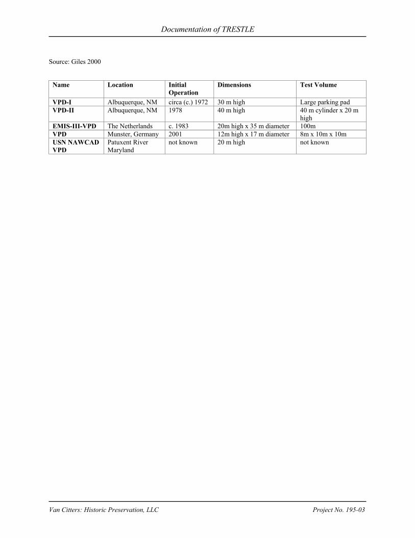
Documentation of TRESTLE
Van Citters: Historic Preservation, LLC Project No. 195-03
Source: Giles 2000
Name
Location
Initial Operation
Dimensions
Test Volume
VPD-I Albuquerque, NM circa (c.) 1972 30 m high Large parking pad VPD-II Albuquerque, NM 1978 40 m high 40 m cylinder x 20 m
high EMIS-III-VPD The Netherlands c. 1983 20m high x 35 m diameter 100m VPD Munster, Germany 2001 12m high x 17 m diameter 8m x 10m x 10m USN NAWCAD VPD
Patuxent River Maryland
not known
20 m high
not known

Documentation of TRESTLE
Van Citters: Historic Preservation, LLC Project No. 195-03
APPENDIX B: EXTANT HYBRID SIMULATORS
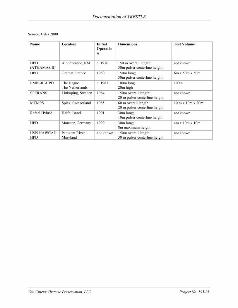
Documentation of TRESTLE
Van Citters: Historic Preservation, LLC Project No. 195-03
Source: Giles 2000
Name
Location
Initial Operation
Dimensions
Test Volume
HPD (ATHAMAS II)
Albuquerque, NM c. 1976 150 m overall length; 30m pulser centerline height
not known
DPH Gramat, France
1980
150m long; 30m pulser centerline height
6m x 50m x 50m
EMIS-III-HPD The Hague The Netherlands
c. 1983
100m long 20m high
100m
SPERANS Linkoping, Sweden 1984
150m overall length; 20 m pulser centerline height
not known
MEMPS Spiez, Switzerland
1985
60 m overall length; 20 m pulser centerline height
10 m x 10m x 20m
Rafael Hybrid Haifa, Israel
1991
30m long; 10m pulser centerline height
not known
HPD Munster, Germany
1999
30m long; 8m maximum height
4m x 10m x 10m
USN NAWCAD HPD
Patuxent River Maryland
not known 150m overall length; 30 m pulser centerline height
not known

Documentation of TRESTLE
Van Citters: Historic Preservation, LLC Project No. 195-03
APPENDIX C: EXTANT GUIDED WAVE SIMULATORS

Documentation of TRESTLE
Van Citters: Historic Preservation, LLC Project No. 195-03
Source: Giles 2000
Name
Location
Initial Operation
Dimensions (overall)
Test Volume
ALECS Albuquerque, NM c. 1967 100 m 12.5 m x 25 m x 13.7 m ARES
Albuquerque, NM 1970
189 m
40 m x 40 m x 33 m
TRESTLE (ATLAS I)
Albuquerque, NM c. 1980
400 m
75 m x 20 m
DREMPS Ottawa, Canada c. 1994 100 m 5 m x 10 m x 10 m DM-1200
Beijing, China
1985
54 m
not known
CNET Guided Wave
Lannion, France
1996
50 m
2.5 m x 2.5 m x 10 m
SSR Gramat, France
1986
106 m
10 m x 23 m x 23 m
DIESES Munster, Germany 1981 120 m 8 m x 10 m x 20 m WIS Indoor Guided Wave Simulator
Munster, Germany
not known
not known
2.75 m x 2.3 m x 6 m
Rafael Guided-wave EMP Simulator
Haifa, Israel
1989
120 m
not known
INSIEME Pisa, Italy c. 1990 120 m 6 m x 10 m x 10 m EMIS-III-TL
The Hauge, The Netherlands
c. 1992
50 m
6 m x 10 m x 6 m
ERU-2M Sergiev Posad-7, Russia
1982
20 m
8 m x 10 m x 8 m
SEMP-6-2M
Sergiev Posad-7, Russia
1982
80 m
15 m x 20 m x 50 m
SEMP-12-3 St. Petersburg, Russia 1992 170 m 10 m x 15 m x 100 m PULSE-M St. Petersburg, Russia 1993 15 m 2.5 m x 5 m x 10 m SAPIENS 2 Linkoping, Sweden 1990 90 m 5 m x 10 m x 10 m VEPES Spiez, Switzerland 1989 55 m 4 m x 8 m x 10 m VERIFY Spiez, Switzerland 1999 20 m 2.5 m x 4 m x 4 m SEMIRAMIS Lausanne, Switzerland 1991 10 m 1 m x 1 m x 3 m GIN-1.6-5 Kharkov, Ukraine 1976 48 m 5 m x 5.6 m x 15 m GINT-12-30 Kharkov, Ukraine 1992 254 m 30 m x 50 m x 50 m IEMP-10 Kharkov, Ukraine 1970 110 m 12 m x 12 m x 20 m IEMI-M5M Kharkov, Ukraine 1992 23 m 3 m x 4 m x 7 m DERA Guided Wave Simulator
Farnborough, UK c. 1967
not known
not known

Documentation of TRESTLE
Van Citters: Historic Preservation, LLC Project No. 195-03
APPENDIX D: U.S. SIMULATORS BUILT DURING THE COLD WAR
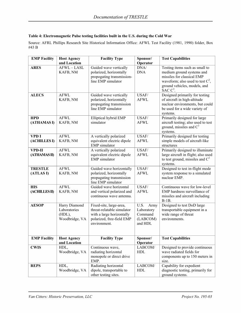
Documentation of TRESTLE
Van Citters: Historic Preservation, LLC Project No. 195-03
Table 4: Electromagnetic Pulse testing facilities built in the U.S. during the Cold War
Source: AFRL Phillips Research Site Historical Information Office: AFWL Test Facility (1981, 1990) folder, Box #43 B
EMP Facility Host Agency and Location
Facility Type
Sponsor/ Operator
Test Capabilities
ARES AFWL – LASL KAFB, NM
Guided wave vertically polarized, horizontally propogating transmission-line EMP simulator
DNA/ DNA
Testing items such as small to medium ground systems and missiles for classical EMP waveform; also used to test C2, ground vehicles, models, and SAC C3.
ALECS AFWL KAFB, NM
Guided wave vertically polarized, horizontally propogating transmission line EMP simulator
USAF/ AFWL
Designed primarily for testing of aircraft in high-altitude nuclear environments, but could be used for a wide variety of systems.
HPD (ATHAMAS I)
AFWL KAFB, NM
Elliptical hybrid EMP simulator
USAF/ AFWL
Primarily designed for large aircraft testing; also used to test ground, missiles and C3 systems.
VPD I (ACHILLES I)
AFWL KAFB, NM
A vertically polarized equivalent electric dipole EMP simulator
USAF/ AFWL
Primarily designed for testing simple models of aircraft-like structures
VPD-II (ATHAMAS II)
AFWL KAFB, NM
A vertically polarized equivalent electric dipole EMP simulator
USAF/ AFWL
Primarily designed to illuminate large aircraft in flight; also used to test ground, missiles and C3 systems.
TRESTLE (ATLAS I)
AFWL KAFB, NM
Guided wave horizontally polarized, horizontally propagating transmission line EMP simulator
USAF/ AFWL
Designed to test in-flight mode system response to a simulated nuclear EMP.
HIS (ACHILLES II)
AFWL KAFB, NM
Guided wave horizontal and vertical polarized and continuous wave antenna.
USAF/ AFWL
Continuous wave for low-level EMP hardness surveillance of missiles and aircraft including B-1B.
AESOP Harry Diamond Laboratories (HDL), Woodbridge, VA
Fixed-site, large-area, threat-relatable simulator with a large horizontally polarized, free-field EMP environment.
U.S. Army Laboratory Command (LABCOM)and HDL
Designed to test DoD large transportable equipment in a wide range of threat environments.
EMP Facility Host Agency and Location
Facility Type
Sponsor/ Operator
Test Capabilities
CWIS HDL, Woodbridge, VA
Continuous wave, radiating horizontal monopole or direct drive EMP.
LABCOM/HDL
Designed to provide continuous wave radiated fields for components up to 150 meters in size.
REPS HDL, Woodbridge, VA
Radiating horizontal dipole, transportable to other testing sites.
LABCOM/HDL
Capability for expedient diagnostic testing, primarily for ground systems.

Documentation of TRESTLE
Van Citters: Historic Preservation, LLC Project No. 195-03
RPG HDL, Woodbridge, VA
Radiating horizontal dipole, transportable to other testing sites; smaller kilovolt capacity than REPS.
LABCOM/HDL
Main function is to provide an EMP source for diagnostic and quick-look data for a wide variety of ground systems.
Suitcase HDL, Woodbridge, VA
Radiating dipole antenna; transportable in a station wagon.
LABCOM/HDL
Primary use to provide a reliable EMP source for diagnostic tests in areas without electric power of utilities.
VEMPS HDL, Woodbridge, VA
Radiating vertical monopole.
LABCOM/HDL
Normally used to test ground systems, but had no limitation on candidate test objects.
VEMPS-II HDL, Woodbridge, VA
Designed to produce a high-frequency vertically polarized EMP environment; radiating vertical monopole.
LABCOM/HDL
Used to test objects 30 x 35 x 15 meter in volume
TES U.S. Navy NATC, Patuxent River, MD
HPD-type, free-field pulse facility
NASC/ NATC
NAVES U.S. Navy NATC, Patuxent River, MD
VPD-type. NATC/ NASC
EMPRESS -II U.S. Navy NSC, Cheatam Annex, Williamsburg, VA
Vertical monopole, transportable into open water.
NSSC/ NSSC
Vulnerability and survivability testing of combat ships and shipboard systems
WESTA White Sands Missile Range
Hybrid - bounded wave and free field radiating technology to produce a horizontally polarized test environment.
WSMR/ WSMR
Documentation of TRESTLE
Van Citters: Historic Preservation, LLC Project No. 195-03
APPENDIX E: MDAC SUBCONTRACTORS
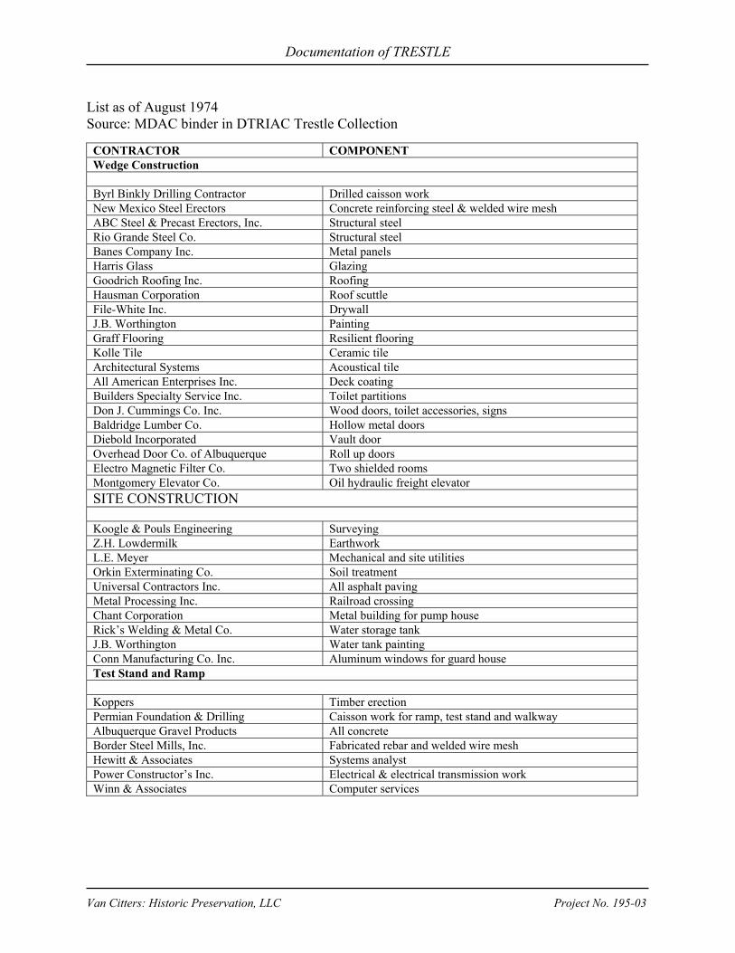
Documentation of TRESTLE
Van Citters: Historic Preservation, LLC Project No. 195-03
List as of August 1974 Source: MDAC binder in DTRIAC Trestle Collection
CONTRACTOR COMPONENT Wedge Construction Byrl Binkly Drilling Contractor Drilled caisson work New Mexico Steel Erectors Concrete reinforcing steel & welded wire mesh ABC Steel & Precast Erectors, Inc. Structural steel Rio Grande Steel Co. Structural steel Banes Company Inc. Metal panels Harris Glass Glazing Goodrich Roofing Inc. Roofing Hausman Corporation Roof scuttle File-White Inc. Drywall J.B. Worthington Painting Graff Flooring Resilient flooring Kolle Tile Ceramic tile Architectural Systems Acoustical tile All American Enterprises Inc. Deck coating Builders Specialty Service Inc. Toilet partitions Don J. Cummings Co. Inc. Wood doors, toilet accessories, signs Baldridge Lumber Co. Hollow metal doors Diebold Incorporated Vault door Overhead Door Co. of Albuquerque Roll up doors Electro Magnetic Filter Co. Two shielded rooms Montgomery Elevator Co. Oil hydraulic freight elevator SITE CONSTRUCTION Koogle & Pouls Engineering Surveying Z.H. Lowdermilk Earthwork L.E. Meyer Mechanical and site utilities Orkin Exterminating Co. Soil treatment Universal Contractors Inc. All asphalt paving Metal Processing Inc. Railroad crossing Chant Corporation Metal building for pump house Rick’s Welding & Metal Co. Water storage tank J.B. Worthington Water tank painting Conn Manufacturing Co. Inc. Aluminum windows for guard house Test Stand and Ramp Koppers Timber erection Permian Foundation & Drilling Caisson work for ramp, test stand and walkway Albuquerque Gravel Products All concrete Border Steel Mills, Inc. Fabricated rebar and welded wire mesh Hewitt & Associates Systems analyst Power Constructor’s Inc. Electrical & electrical transmission work Winn & Associates Computer services

Documentation of TRESTLE
Van Citters: Historic Preservation, LLC Project No. 195-03
APPENDIX F: TRESTLE PROGRESS DATA
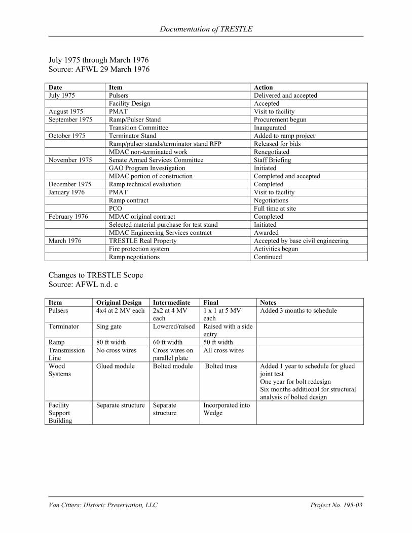
Documentation of TRESTLE
Van Citters: Historic Preservation, LLC Project No. 195-03
July 1975 through March 1976 Source: AFWL 29 March 1976 Date Item Action July 1975 Pulsers Delivered and accepted Facility Design Accepted August 1975 PMAT Visit to facility September 1975 Ramp/Pulser Stand Procurement begun Transition Committee Inaugurated October 1975 Terminator Stand Added to ramp project Ramp/pulser stands/terminator stand RFP Released for bids MDAC non-terminated work Renegotiated November 1975 Senate Armed Services Committee Staff Briefing GAO Program Investigation Initiated MDAC portion of construction Completed and accepted December 1975 Ramp technical evaluation Completed January 1976 PMAT Visit to facility Ramp contract Negotiations PCO Full time at site February 1976 MDAC original contract Completed Selected material purchase for test stand Initiated MDAC Engineering Services contract Awarded March 1976 TRESTLE Real Property Accepted by base civil engineering Fire protection system Activities begun Ramp negotiations Continued Changes to TRESTLE Scope Source: AFWL n.d. c Item Original Design Intermediate Final Notes Pulsers 4x4 at 2 MV each 2x2 at 4 MV
each 1 x 1 at 5 MV each
Added 3 months to schedule
Terminator Sing gate Lowered/raised Raised with a side entry
Ramp 80 ft width 60 ft width 50 ft width Transmission Line
No cross wires Cross wires on parallel plate
All cross wires
Wood Systems
Glued module Bolted module Bolted truss Added 1 year to schedule for glued joint test One year for bolt redesign Six months additional for structural analysis of bolted design
Facility Support Building
Separate structure Separate structure
Incorporated into Wedge

Documentation of TRESTLE
Van Citters: Historic Preservation, LLC Project No. 195-03
APPENDIX G: 1976 TRESTLE TASKS
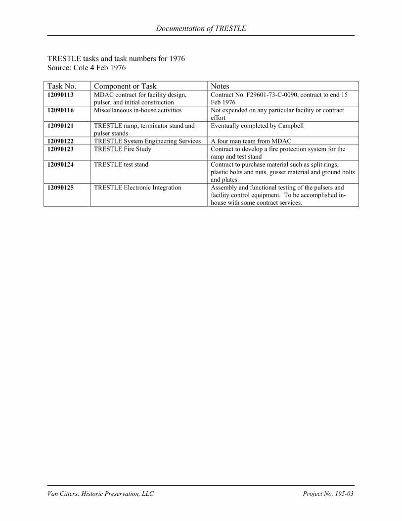
Documentation of TRESTLE
Van Citters: Historic Preservation, LLC Project No. 195-03
TRESTLE tasks and task numbers for 1976 Source: Cole 4 Feb 1976 Task No. Component or Task Notes 12090113 MDAC contract for facility design,
pulser, and initial construction Contract No. F29601-73-C-0090, contract to end 15 Feb 1976
12090116 Miscellaneous in-house activities Not expended on any particular facility or contract effort
12090121 TRESTLE ramp, terminator stand and pulser stands
Eventually completed by Campbell
12090122 TRESTLE System Engineering Services A four man team from MDAC 12090123 TRESTLE Fire Study Contract to develop a fire protection system for the
ramp and test stand 12090124 TRESTLE test stand Contract to purchase material such as split rings,
plastic bolts and nuts, gusset material and ground bolts and plates.
12090125 TRESTLE Electronic Integration Assembly and functional testing of the pulsers and facility control equipment. To be accomplished in-house with some contract services.


