1. INTRODUCTIONSchematic eye models that can reproduce optical proper-ties from anatomy are especially useful. They can beused in the design of ophthalmic or visual optics, to simu-late experiments, to predict the effect of refractive sur-gery or implants, or just to understand better the role ofthe different optical components, among other applica-tions. Furthermore, schematic eyes are necessary evento estimate basic (first-order) optical properties of the eye(i.e., the focal length). The famous Gullstrand eye1
(based on an older model by Listing), later updated by LeGrand,2 has been highly successful and is still in usenowadays, because it is simple, is based on anatomy, andreproduces the Gaussian properties of an average eye.
From this basic model, there have been two main ten-dencies. On the one hand, simplified reduced eyes havebeen derived. Although Le Grand2 pointed out that it isnecessary to avoid the use of the reduced eye becausesuch a scheme is too crude, reduced eyes can be specifi-cally designed to reproduce some ocular aberrations3,4 oreven as wide-angle models to reproduce obliqueastigmatism.5
On the other hand, other authors have attempted to fol-low anatomy more accurately,6–8 incorporating agradient-index (GRIN) crystalline lens, which is some-times approximated by a shell structure.9 Nevertheless,the exact distribution of the refractive index of the humanlens is not well known yet, and these models tend to have
several adjustable parameters. Less attention has beenpaid to including other anatomical features in eye models,such as decentering of lenses and iris or other nonaxiallysymmetric features that potentially have a strong effecton optical performance. In fact, rotationally symmetriceyes are incomplete in the sense that they predict onlyspherical and chromatic aberration in the fovea, whereasreal eyes display astigmatism, coma, and irregular aber-rations as well.10–13
These opposite tendencies demonstrate that there is nogeneral agreement in modeling the eye. The jointanatomical–optical type of modeling is still open for re-search and discussion. Our approach is to try to harmo-nize these opposite tendencies with a schematic eye modelthat can offer a trade-off between accuracy and economy(simplicity). Ideally, an eye model should reproduce ac-curately both anatomy and optical properties (first order,aberrations, and image quality). However, such a modelcould eventually become highly complicated yet not beuseful because of low accuracy. Maybe one would findthat there is a lack of reliable experimental data on im-portant parameters necessary to build the model and endup with a model of not much use in practice because of thehigh intersubject variability.
The Gullstrand–Le Grand eye accomplishes the above-mentioned trade-off, except that it exhibits substantiallyhigher aberrations than normal emmetropic eyes. Tobetter predict optical performance, spherical
1999 Optical Society of America
1882 J. Opt. Soc. Am. A/Vol. 16, No. 8 /August 1999 I. Escudero-Sanz and R. Navarro
aberration,4,8,14 and oblique astigmatism15–17 or to buildwide-angle eye models,18 it is necessary to include as-pheric surfaces. However, it is not possible to predict theoptical performance of real human eyes on axis with a ro-tationally symmetric model. Nevertheless, the great ma-jority of schematic eyes have axial symmetry, thus allow-ing prediction of only chromatic and spherical aberrationson axis. Many authors have attempted to measure thespherical aberration of the eye, often finding that the ab-erration changes with the orientation (or the meridian).This lack of rotational symmetry suggests the presence ofother aberrations, since spherical aberration is rotation-ally symmetric by definition. However, one should bearin mind that a simple pupil decentering can convert partof the spherical aberration and defocus into coma andastigmatism and that any nonaxially symmetric featureor local defect will yield an overall aberration that may befar from having even symmetry. Nevertheless, if we con-sider a large population of different eyes and assume thatdepartures from axial symmetry are randomly but uni-formly distributed, the average of their aberration pat-tern will tend to be symmetric. In this sense a schematiceye model may reproduce the expected amount of aberra-tion but not the highly irregular patterns found in indi-vidual eyes.
One can even argue that a wide-angle model should beable to reproduce the main features of off-axis perfor-mance but not try to fit exactly each aberration at everyretinal location. The latter would be a difficult task toundertake, and besides there are not enough experimen-tal data to even attempt it. In fact, only a few authorshave attempted to reproduce off-axis aberrations withwide-angle model eyes (except for obliqueastigmatism16,17 or chromatic aberration19). One impor-tant reason was simply that no data on some aberrations,such as peripheral coma, were available.
Thus the first goal of this work is to build a wide-anglemodel, departing from a simple schematic eye, that repro-duces on-axis optical performance reasonably14 in order toreproduce off-axis performance by adding a minimum ofchanges. We believe that this is one of the first attemptsto reproduce aberrations and overall performance acrossfield angle, and we think that it is worth trying. A sec-ondary goal, which is a potentially interesting applicationof this wide-angle model, is to compare aberrations in theobject and image spaces. Thibos et al.4 have alreadypointed out the difference between the object and imagespaces in the particular case of spherical aberration. Theknowledge of object aberrations is of interest for applica-tions such as fundus imaging, where the retina is viewedthrough the optical system of the eye, but it is more im-portant to know image (retinal) aberrations, since theylimit visual perception. However, aberrations are, inmost cases, measured in the object space instead of in theimage space, because the retinal image is not accessibleeasily, and only very few methods, among those proposedin the literature, measure aberrations in the image spacesubjectively10 and objectively.12 In this sense the modeleye permits us to compute aberrations in either the objector the image space and may help to estimate the potentialbiases of experimental measurements of ocular aberra-tions by subjective and objective techniques.
2. WIDE-ANGLE SCHEMATIC EYEThe eye model proposed and studied here is an extensionof that by Navarro et al.,14 which is similar to Kooijman’swide-angle model.18 That model was built by incorporat-ing published conic constant anatomical values into theGullstrand–Le Grand spherical surfaces2 and updatingthe value of the anterior radius and the refractive index ofthe cornea with the use of more recent anatomical data.The same refractive indices as those in Ref. 2 were usedfor the other ocular media and for the standard D line(589.3-nm wavelength). Refractive indices for otherwavelengths were estimated, departing from experimen-tal data of chromatic dispersions and adjusting experi-mental values of the longitudinal chromatic aberration(LCA) (see Ref. 14 for details).
The optical quality of that schematic eye (spherical andchromatic aberrations, as well as polychromatic point-spread functions and modulation-transfer functions(MTF’s) have already been studied in Ref. 14 but only onaxis. One important feature of that model, which hasbeen kept here, is that all parameters that define its ge-ometry are anatomical, and there was no need to fit orchange original values to reproduce average data onspherical aberration. Refractive indices, especially forl 5 589.3 nm, were also anatomical, except for theGRIN structure of the lens. In that case the equivalentconstant index used by Gullstrand and Le Grand to repro-duce the refractive power of the lens was adopted here.
To extend this on-axis schematic eye to a wide-anglemodel, we have made a small modification: the additionof a curved image surface (the retina) having the simplestshape, i.e., spherical, with a 12-mm radius of curvature.2
This image surface is intersected by the optical axis at theparaxial focus for 543 nm, which has been the referencewavelength in this work. (This choice is arbitrary, but itis appropriate to compare the model predictions with re-cent experimental data that are being obtained in differ-
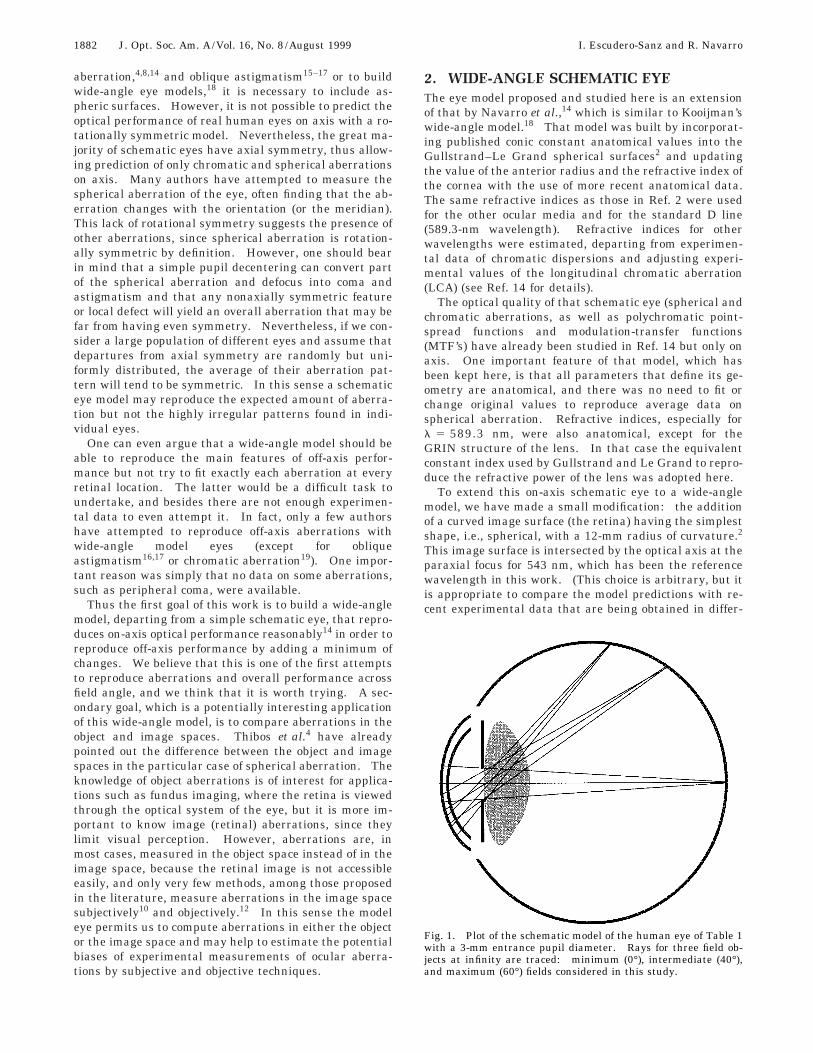
Fig. 1. Plot of the schematic model of the human eye of Table 1with a 3-mm entrance pupil diameter. Rays for three field ob-jects at infinity are traced: minimum (0°), intermediate (40°),and maximum (60°) fields considered in this study.
I. Escudero-Sanz and R. Navarro Vol. 16, No. 8 /August 1999 /J. Opt. Soc. Am. A 1883
Table 1. Geometry of the Schematic Wide-Angle Eye Model
Surface Type Conic Constant Radius (mm) Thickness (mm) Optical Medium
ent laboratories with green He–Ne lasers. In addition,this wavelength is close to the maximum of the spectralluminous efficiency function for the standard observer(Vl): lmax ' 555 nm.) The schematic eye is depicted inFig. 1, and Tables 1 and 2 show the geometrical param-eters and the refractive indices, respectively. For l5 543 nm, the focal length of this schematic eye is 22.03nm in the image space (the effective focal length in air is16.47 mm), and the refractive power is 60.7 diopters (D).The entrance pupil position is 3.04 mm from the first sur-face, and the exit pupil position is 23.92 mm from theback surface of the eye lens.
All ray tracing, wave-front analysis, and MTF compu-tations have been carried out with Zemax optical designsoftware. Third-order calculations are based on theSeidel wave-front coefficients through paraxial ray trac-ing of marginal and chief rays.20
In what follows, aberrations have been estimated inthree ways (in most cases): (1) by finite ray tracing, (2)by computation of third-order Seidel coefficients, and (3)by simulation of experiments taken from the literature byfinite ray tracing (usually by computing aberrations inthe object space). In several cases our schematic eye pre-dicts substantial offsets between aberrations in the objectspace (simulating experimental data) and in the imagespace computed by applying standard definitions.
3. ABERRATIONS: MODEL PREDICTIONSAND EXPERIMENTAL DATAIn this section the aberrations of the schematic eye intro-duced in Section 2 are computed and compared with ex-perimental data published in the literature. As we saidabove, three different calculations of the aberrations ofthe model have been carried out that include aberrationscomputed by modeling experiments described in the lit-erature. In this way we can (1) test how well the modelreproduces the optical quality of real eyes on and off axisand (2) predict biases between experimentally measuredaberrations with different techniques and theoreticalimage-domain (retinal) values. Unless stated otherwise,
Table 2. Refractive Indices for the WavelengthsUsed in Computations
standard calculations have been carried out for light of543-nm wavelengths. Results for longitudinal aberra-tions (defocus, spherical aberration, astigmatism, etc.) aregiven in terms of differences in refractive power in diopt-ers, and transverse aberrations (coma, transverse color,spot diagrams, etc.) are given as angular displacements inarc minutes.
A. Spherical AberrationSpherical aberration has been widely studied in the lit-erature and still is one of the most controversial subjectsregarding aberrations of the eye. Not only the absolutevalue of this aberration but also its relative contributionto the overall ocular optical performance is a source of dis-agreement. On the one hand, specific methods for the di-rect measurement of the longitudinal spherical aberra-tion (LSA)21 tend to yield large amounts of aberration(typically 2–3 D for 8-mm pupil diameter); thus thesestudies attribute a major role to this aberration in theoverall performance of the system on axis. On the otherhand, relatively small values of spherical aberration areobtained with experimental methods designed to measurethe overall wave-front aberration,10–13 thus leading to theopposite conclusion. Moreover, in the latter type ofstudy, Zernike coefficients of astigmatism and coma aremore important than the corresponding spherical aberra-tion coefficients in individual eyes. We are aware of thiscontroversy but here have adopted the experimental val-ues given by the first type of method because we believethat they better represent average data (over subjects buttypically also over orientations), whereas overall wave-front data better describe individual eyes. Furthermore,Charman and Walsh22 averaged wave aberration experi-mental data over all meridians and estimated the result-ing geometrical ‘‘spherical’’ aberration. They comparedtheir results with those of earlier authors for the spheri-cal aberration, concluding that the results for both kindsof measurements agree reasonably well.
The LSA has been computed for a maximum entrancepupil of 8 mm, and the results are given in Fig. 2. It in-cludes third-order (Seidel, dashed curve) and finite ray-tracing computations of the LSA for the schematic eyemodel (solid curve) and computer simulations of the ex-periments by Koomen et al.,21 as well as the experimentalvalues obtained by these authors (triangles), data fromseveral authors compiled by van Meeteren23 (solidsquares), and values obtained by Thibos et al.4 (opencircles). The units are diopters, that is, the aberrationmeasured as the difference between the reciprocals of op-tical distances (n/l). (For instance, the aberration in ourcalculations is the product of the refractive index n8 with
1884 J. Opt. Soc. Am. A/Vol. 16, No. 8 /August 1999 I. Escudero-Sanz and R. Navarro
the difference between the reciprocal of the paraxial focallength and the reciprocal of the distance between the im-age principal plane and the focus of the rays through agiven pupil radius.) We can see that the agreement ofour computations with the data of van Meeteren and Thi-bos et al. is almost perfect. However, it is important toremember the different natures and origins of these setsof data: van Meeteren’s data are the result of a curve fit-ting to the experimental data available in the literatureat that time; Thibos et al. adjusted the shape of a single-surface reduced eye to reproduce experimental values ofthe LSA; in contrast, our schematic eye reproduces thesame LSA by using anatomical data without any fitting.
To simulate the experiment by Koomen et al.,21 wehave introduced annular apertures placed 5 mm in frontof the cornea into our model eye. In their experiment,which we have simulated here, these apertures had dif-ferent radii so that the pupil could be sampled in the ra-dial variable but rays could be integrated in the angularvariable. For each pupil radius (aperture), the distancefrom the point object to the eye was changed until the im-age was on focus at the retina. The conjugate lens equa-tion (2n/l 1 n8/l8 5 n8/f8, where n and n8 are the re-fractive indices of air and aqueous humor, respectively; f8is the focal length; and l and l8 are the distances from theobject and the image to the corresponding object and im-age principal planes, respectively), is then used to find thevalue of the spherical aberration for that radius. Writingthis equation, both for the data obtained for a given ra-dius (r) and for the reference paraxial case ( p), subtract-ing both expressions and using the fact that the imagedistance is fixed (l8 5 constant) and that it does notchange with radius, we find that the LCA in diopters for agiven radius is
where lp and lr are the object distances to focus the imagefor the paraxial circle (r 5 0) and for the ring of radius r,respectively. It can be seen in Fig. 2 that experimentalvalues by Koomen et al. (triangles) are slightly above theresults of our computer simulation (solid circles), but the
Fig. 2. Longitudinal spherical aberration (LSA) of the sche-matic eye with an 8-mm-diameter entrance pupil, compared withexperimental data taken from the literature, in diopters (see thesymbol key and the text for details).
overall agreement is reasonable and is much better if weconsider average data.4,23 Therefore, if one considersspherical aberration as the angular average of ocular ab-errations, as Koomen et al. and others did, then real eyesseem quite well represented by the schematic model.Equally, the results of this simulation and the actualspherical aberration of the model (solid curve) are verymuch alike, which indicates the validity of this kind of ex-periment. We want to recall that in the schematic eyemodel14 the conic constants (aspheric surfaces) control theLSA, which is much lower than in the Gullstrand eye(spherical surfaces). This aberration control includeshigher-order LSA, so that the third-order Seidel (e.g., seeRef. 20) term yields a good approximation of the total LSAfor pupil diameters up to 6 mm.
B. ComaUntil recently there was a lack of experimental data ofcoma except at the fovea. As we said above, the currentversion of our schematic model is rotationally symmetricand thus does not display coma on axis, but here we areinterested in studying the schematic model as a wide-angle eye and hence its off-axis aberrations. As far as weknow, there is only one recent, systematic study of the off-axis overall monochromatic aberrations in the humaneye.24 In that study, aberrations are measured at the im-age plane by a laser ray-tracing technique, thus being di-rectly comparable with the finite ray-tracing computa-tions carried out here. Nevertheless, other methods,either objective11 or subjective,25 measure aberrations inthe object space. We have simulated the latter, subjec-tive methods, which are based on measurements of thechange from the direction of rays (coming from a point ob-ject at infinity) in the object space to the direction atwhich the rays intersect the principal ray at the imagesurface (the retina).
The results of computations of angular coma, for mar-ginal rays in an 8-mm entrance pupil, are presented inFig. 3. The third-order tangential and sagittal coma, de-rived from Seidel coefficients20 (dotted curves), are com-pared with the more exact values (solid curves), obtainedas the difference between the angle of finite marginal raysin the image space and the angle of an ideal ray, which
Fig. 3. Tangential and sagittal angular coma, in arcminutes, ofthe schematic eye, compared with experimental tangential coma.
I. Escudero-Sanz and R. Navarro Vol. 16, No. 8 /August 1999 /J. Opt. Soc. Am. A 1885
would form a nonaberrated image. In the case of tangen-tial coma, the aberration is the mean of the values of di-agonally opposite marginal rays. The figure also in-cludes a simulation of what would be expected in thesubjective experiment (circles), which predicts a small butsignificant bias, tending to overestimate tangential coma.Interestingly, we can appreciate in the figure how third-order coma is larger than the actual value (especially tan-gential coma). This suggests that the optical design ofthe eye is helping to maintain aberrations within moder-ate levels: it seems clear that higher-order terms areplaying a compensating role, helping to control this aber-ration. Average experimental data of third-order tan-gential coma, estimated from Zernike coefficients,24 arerepresented as squares. We can see that experimentaldata differ from those of the model for zero or small fieldangles, simply because the symmetric model cannot pre-dict any coma on-axis. However, the two sets of datatend to merge, which results in a much better agreementfrom 20° to 40°. Thus the model seems to be capable ofcapturing the overall wide-angle behavior, that is, thefield aberration, but it cannot reproduce on-axis coma un-less it incorporates some asymmetric features.
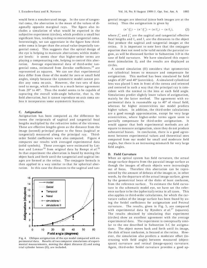
C. AstigmatismAstigmatism has been computed as the difference be-tween the reciprocals of sagittal and tangential focallengths multiplied by the refractive index of the vitreous.These are effective lengths given as the distance from theimage (second) principal plane to the focus (sagittal ortangential) measured along the principal ray. Third-order Seidel coefficients were also computed. Figure 4compares our results with averaged experimental data(solid symbols). These averages were estimated by Lot-mar and Lotmar16 from original data by Rempt et al.26
In that experiment the aberration is found by moving theobject back and forth until the tangential and sagittal im-ages are formed at the retina. The conjugate formula isthen applied in a way similar to that for spherical aber-ration. In this case the distances to the sagittal and tan-
Fig. 4. Oblique astigmatism of the eye model compared with ex-perimental data. Results of two computer simulations of experi-mental measurements, moving the object distance (I) and usingtrial cylinder lenses (II), are included.
gential images are identical (since both images are at theretina). Thus the astigmatism is given by
~n8/ft! 2 ~n8/f s8! 5 ~n/ls! 2 ~n/lt!, (2)
where f s8 and f t8 are the sagittal and tangential effectivefocal lengths and ls and lt are the distances to the objectthat produce the sagittal and tangential images at theretina. It is important to note here that the conjugateequation does not need to be valid outside the paraxial re-gion, as will be discussed further in Subsection 3.D in thecase of field curvature. We have simulated this experi-ment (simulation I), and the results are displayed ascircles.
A second simulation (II) considers that optometristsuse cylindrical lenses to measure and compensate forastigmatism. This method has been simulated for fieldangles of 20° and 40° (asterisks). A simulated cylindricallens was placed 5 mm in front of the cornea and orientedand centered in such a way that the principal ray is coin-cident with the normal to the lens at each field angle.Simulations predict slightly lower values of astigmatism,mainly for the latter method. The agreement with ex-perimental data is reasonable up to 40° of visual field,whereas for higher eccentricities our model predictshigher values. In addition, the third-order calculationsare a good enough approximation, except for very largeeccentricities, where higher-order terms again seem topartially compensate for third-order astigmatism. Itwould appear that both experimental methods are ad-equate to measure astigmatism, since they do not producesubstantial biases. In conclusion, there is a good agree-ment between experimental values and theoretical onescomputed from our model for small and moderate fieldangles, but there is an increasing mismatch for very largefield angles.
D. Field CurvatureWhen an optical system has field curvature, the actualimage surface departs from the paraxial image surface asthough the images of off-axis objects were increasinglyout of focus. Therefore this aberration can be repre-sented by the amount of defocus of the images or, in otherwords, by the departure of the actual image surface, givenby the geometrical locus of the disks of least confusion,from the reference surface. To estimate the field curva-ture in the schematic model eye, we have set the refer-ence surface to be the (spherical) retina in all cases. Thisalso applies to third-order calculations, for which the cur-vature radius of the image surface has been found by us-ing the Seidel coefficients for astigmatism and Petzvalcurvature. The results, given in Fig. 5, are comparedwith experimental data by Rynders et al.27 (squares).The results obtained by simulating that experiment(circles) show an excellent agreement with the averageexperimental data. The experiment is conceptually simi-lar to the one described in Subsection 3.C for astigma-tism: The object moves back and forth until its image,the disk of least confusion, is focused at the retina. How-ever, the simulation also predicts a moderate offset (in-creasing with field angle) between measured (object-space) curvature and retinal (image-space) curvature.Again, third-order Seidel curvature provides a good ap-
1886 J. Opt. Soc. Am. A/Vol. 16, No. 8 /August 1999 I. Escudero-Sanz and R. Navarro
proximation to the total value for field angles up to 40°.In this case the curvature of the retinal surface, instead ofhigher-order terms, is the major force controlling this ab-erration.
Figure 6 compares the curvature of the retinal surfaceversus the different image curvatures mentioned above.These are the Petzval surface [a 17-mm-radius sphere(asterisks)], the third-order image surface [a 13-mm-radius sphere (circles)], the image surface obtained by fi-nite ray tracing (solid curve), and the retina [a 12-mm-radius sphere (dotted curve)]. The origin of coordinatesis the paraxial focus at l 5 543 nm. Under this repre-sentation the good overall match between both retinaland image surfaces appears much clearer. Although ourspherical retinal surface is a rather crude approximationto the actual shape of the retina in individual eyes, it cap-tures the essential fact that retinal curvature seems welladapted to compensate for the curvature of the image sur-face.
Analysis of Figs. 5 and 6 leads to the conclusion thatthis schematic model is a good representation of the eye,as the good agreement between experimental and simu-lated data shows. It is worth noting that field curvatureoften is the most important aberration in a wide-angle op-tical system. If there were not a good match between theoptical image and the retinal surface, defocus could reachhuge values in the periphery (as suggested by Fig. 6).Thus a wide-angle model that provides a good agreementwith experimental field curvatures, such as this one, aswell as a reasonable fit to the order of magnitude of otheraberrations, will be able to make good predictions of theoverall optical quality of an average eye. Figure 5 sug-gests that the experimental method followed by Rynderset al.27 tends to overestimate field curvature at large ec-centricities, probably because it uses the conjugate equa-tion far off the paraxial region. Figures 5 and 6 togetherreveal an interesting feature of the optical design of theeye: The astigmatism contributes to the correction offield curvature in the sense of bending the image surfacecloser to the retina rather than in the sense of flattening
Fig. 5. Field curvature of the eye model, estimated as the offset,in diopters, between the least confusion disk (LCD) and theretina (solid curve); third-order LCD (dotted curve); experimen-tal data (solid squares); and computer simulation of the experi-ment (open circles).
the field (as happens in a Petzval lens, for instance).This is shown clearly in Fig. 6, where the departure of thePetzval surface from the retina is larger than that of thesurface containing the disks of least confusion. The ex-perimental values of astigmatism and field curvatures(Figs. 4 and 5) also support this idea, suggesting that thisjoint compensation (astigmatism and retinal curvature)could actually be taking place in nature.
E. DistortionAlthough it is hard to estimate distortion in the humaneye experimentally, we include predictions of our eyemodel here (Fig. 7) to complete our analysis. Again, it isclear that higher-order terms tend to compensate forthird-order distortion in the eye model, mainly for highereccentricities, where the overall distortion shows moder-ate values.
Fig. 6. Shape and relative location of the different image sur-faces of the eye: Model surface (solid curve), computed as thelocus of the disks of least confusion for finite ray tracing with theuse of a 3-mm pupil, is compared with the Petzval surface (aster-isks), with the disks of least confusion in third-order approxima-tion, and finally with the retinal surface that is approximated bya sphere in the eye model.
Fig. 7. Angular distortion of the eye model. (We have notfound experimental data available.)
I. Escudero-Sanz and R. Navarro Vol. 16, No. 8 /August 1999 /J. Opt. Soc. Am. A 1887
F. Longitudinal Chromatic AberrationLongitudinal color, chromatic difference of focus, andLCA of this schematic eye model have been reportedpreviously,14 showing a close match with experimentaldata. Although the LCA is not expected to change muchwith field angle, this could be somewhat different forlarge field angles because of potential changes in the ef-fective refractive power. In a recent work by Rynderset al.,27 the LCA has been measured as a function of vi-sual field, yielding a slightly higher LCA for large visualangles. Here we report a simulation of that experimentwith the same wavelengths—632.8, 543, and 458 nm—that were used in the experiment. As we said in Subsec-tion 3.D, that experiment makes use of the conjugateequation to estimate the LCA, even though the experi-mental conditions did not guarantee the validity of theGaussian approximation. The procedure consisted ofchanging the object distance to obtain the best imagequality (focus) at the retina. When we write the conju-gate equation for two colors (red and blue, for instance)and simplify the term corresponding to the image dis-tances, the image plane LCA between these wavelengthsis given by
This expression was also used here to simulate the experi-ment. The results are presented in Fig. 8. These in-clude the variation of chromatic difference of effectivepower (which corresponds to the effective focal length de-fined in Subsection 3.C), that is, the LCA of the eye modelas a function of field angle (solid curve); experimentaldata (squares; error bars indicate intersubject variabil-ity); the results of simulating this experiment with themodel eye (curve with circles); and, finally, the results ofthe same simulation, but now including a correction term(dotted curve with asterisks). This correction term takesinto account that not only the refractive power but alsoother Gaussian parameters, such as the positions of theprincipal planes of the eye model, varies with color. If wetake into account that the position of the image principalplane does not change with wavelength, we arrive at thecorrect expression that links the LCA with measurementscarried out in the object space:
~nr8/fr8! 2 ~nb8/fb8 ! 5 ~nb /lb! 2 ~nr /lr!
1 ~nr8/lr8! 2 ~nb8/lb8 !. (4)
This is a typical example in which an eye model can be ofvaluable help. The correcting term (nr8/lr8)2 (nb8/lb8), could not be determined experimentally, butthe eye model can provide an estimation, thus permittingfurther refinements of the LCA measurements. In fact,we can see in Fig. 8 that the experimental values(squares) and the results of the simulation (without cor-recting term) (circles) are similar (simulation results arewithin the range covered by experimental error bars, ex-cept for an anomalous point at 5°), but both differ fromthe image-space LCA estimated from the model. Thereason for this discrepancy is that the experimentalmethod measures the aberration in the object space, thatis, the amount (nb /lb) 2 (nr /lr). If we want to estimatethe aberration in the image space from these experimen-
tal data, it is necessary to know the correcting term(nr8/lr8) 2 (nb8/lb8), which accounts for changes in the posi-tion of the image principal plane with wavelength. If wecan determine it (by experiment or simulation), then Eq.(4) permits a better approximation to the LCA. We cansee in Fig. 8 that the agreement between the model,image-space LCA (solid curve) and the data of the cor-rected simulation, that is, the data obtained by computingthe LCA in the object space and then applying Eq. (4) (as-terisks), is much closer. However, the results of the un-corrected simulation (open circles) are consistent with theexperimental data that were not corrected. In this casethere is a substantial bias between the aberrations in theobject and image spaces.
G. Transverse ColorThe computation of the transverse chromatic aberration(TCA) with finite ray tracing involves finding the changein direction of the principal ray in the image space for dif-ferent wavelengths. The experimental data reported inthe literature have been obtained by applying the sameidea, but as in many other cases, the change in directioncan be measured only in the object space. Despite thesparse literature available measuring the TCA across thevisual field, there are large discrepancies in the experi-mental data reported by different authors. Thiboset al.19 discard the Ogboso and Bedell data,28 citing theirlarge experimental errors, but, nevertheless, we includeboth sets of data here. These experimental data, alongwith the results of the eye model and simulations, areshown in Fig. 9. This figure contains six sets of data:transverse color of the schematic eye model, obtained byfinite ray tracing at 572 nm and 435 nm, the wavelengthsused by Ogboso and Bedell28 (thick solid curves); data ob-tained in the simulation of that experiment with theabove wavelengths (curve with open circles); the originalexperimental data28 obtained, along both the temporal(solid circles) and nasal (squares) meridians; data fromThibos et al.19 for wavelengths 433 nm and 622 nm, cor-responding to an experimental simulation in which theoff-axis TCA was inferred from measurements of the
Fig. 8. Variation of longitudinal color (LCA) with field angle forthe schematic eye model (solid curve), along with experimentaldata (solid squares) and simulations of that experiment, both di-rect simulation (open circles) and corrected from estimated bias(asterisks).
1888 J. Opt. Soc. Am. A/Vol. 16, No. 8 /August 1999 I. Escudero-Sanz and R. Navarro
foveal TCA as a function of the displacement of an artifi-cial pupil (solid diamonds); and our simulation of the TCAfor the wavelengths used in the latter experiment (opendiamonds). From this figure we can extract several con-clusions. Simulated experiments (that is, object-spaceTCA) predict a moderate overestimation of the TCA in theimage space given by the model. The offset between theobject and image values is approximately proportional tothe value of the TCA. There is a close agreement be-tween experimental and simulated data for the Thiboset al. study, which suggests that (1) experimental datacould be biased in a similar manner to that of simulationand (2) if that is true, the schematic eye yields a good pre-diction of the off-axis TCA. Furthermore, at large fieldangles, the agreement found here is even better than thatobtained with the model developed by the authors19 to fitthe data of the experiment. However, the agreement isworse with the results of the experiment by Ogboso andBedell.
4. OVERALL PERFORMANCESpot diagrams, shown in Figs. 10 and 11, have been com-puted to provide a more general view of the ability of theschematic eye model to reproduce the overall optical per-formance of the eye as a wide-angle optical system.Again, in the computations, we have tried to follow ex-perimental conditions for the data available in the litera-ture. As far as we know, there is only one recent study24
reporting experimental spot diagrams across the visualfield, and thus we have reproduced those ray-tracing con-ditions in Fig. 10: 1-mm sampling interval in a squaregrid, 6-mm pupil diameter, and 543-nm wavelength. Theresults for 0°, 5°, 10°, 20°, 40°, and 60° of field are shownin Fig. 10. Each box represents 300 3 300 mm at theretina (300 mm ' 1° of field). If we compare these dia-grams with experimental data (results for four subjectsand for the same visual angles, except for 60°, can befound in Fig. 2 of Ref. 24), there is a notable agreement inthe overall features in spite of large intersubject differ-ences in experimental data. Namely, the overall size ofthe spot diagrams is similar, and the change of opticalquality with field angle is slow and gradual, as one would
Fig. 9. Transverse color TCA for the model, experimental data,and computer simulations.
like to have in a wide-angle lens. In addition, the pat-terns provided by the model strongly resemble some indi-vidual patterns found experimentally. Spherical aberra-tion (on-axis), coma, and astigmatism are apparent in Fig.10. Although field curvature is not really seen, imageswith less astigmatism could be obtained at large fieldangles for slightly larger radii of the image surface,whereas no significant change is observed at any fieldangle if a defocus is introduced. There is some field cur-vature present, but astigmatism is the dominant effect atlarge field angles while coma is the dominant effect atmoderate angles.
Figure 11 shows spot diagrams for smaller (3-mm) andlarger (9-mm) pupil diameters for 0° and 40° field angles.For smaller pupils the spot diagram is very small on-axis,since the model eye is nearly diffraction limited, but theimage quality declines with eccentricity because of astig-matism and coma. For large apertures (9-mm pupil, notshown here), spherical aberration is the limiting aberra-tion, making the spatial resolution almost uniform overall the field.
Figures 12(a) and 12(b) display the MTF of the sche-matic eye for field angles 0° and 20°, respectively. In thiscase the calculations were carried out at l 5 632.8 nmand for a 4-mm-diameter entrance pupil in order to com-
Fig. 10. Spot diagrams for the schematic eye, obtained by finiteray tracing, for a 6-mm entrance pupil diameter and for six fieldangles: 0°, 5°, 10°, 20°, 40°, and 60°.
Fig. 11. Spot diagrams for 3-mm and 9-mm pupil diameters andfor 0° and 40° field angles.
I. Escudero-Sanz and R. Navarro Vol. 16, No. 8 /August 1999 /J. Opt. Soc. Am. A 1889
pare the results with experimental values.29 In bothplots the MTF of the model, averaged across orientations,is compared with two sets of experimental data.29,30
These two experiments differ in wavelength, 632.8 nmversus 543 nm; pupil diameter, 4 mm versus 3 mm; and inexperimental conditions, natural viewing conditions ver-sus best image plane with paralyzed accommodation.Therefore they yield somewhat different results, mainlyon-axis. We can see that while the agreement betweenmodel and experimental data is quite good off axis (20°),it is worse on axis. In the last case, the MTF for 0.15 D ofdefocus has been included, following van Meeteren’s sug-gestion that the effect of irregular aberrations—coma,etc.—on the MTF would be equivalent to that of 0.15 D ofdefocus. We can see that the MTF data of Williamset al.30 lie between both theoretical curves (except at verylow frequencies), tending to fit the theoretical MTF forzero defocus at higher frequencies, whereas the data ofNavarro et al.29 tend to fit the theoretical MTF for 0.15 Dof defocus at mid–high frequencies. The MTF’s for otherfield angles have been computed as well but are notshown here. In summary, the agreement between ex-perimental and simulated MTF curves is close for moder-ate field angles, being worse at the fovea but also at very
Fig. 12. Radial profiles (orientation average) of the MTF of theeye model compared with experimental data available in the lit-erature. (a) On-axis. Here the MTF has been computed for 0and 0.15 D of defocus. (b) 20° off-axis.
large fields (60°) as a result of the mismatch between ex-perimental and model astigmatism (see Fig. 4).
5. DISCUSSION AND CONCLUSIONSA schematic eye model based on anatomical data, whichhad been designed previously to reproduce image qualityon axis,14 has been transformed into a wide-angle model,simply by adding a spherical image surface that plays therole of the retina. This model was designed on the crite-rion of the minimum complexity necessary to reproduce,with a reasonable accuracy, the experimental average op-tical performance of the eye across the visual field. Oneof the most important features of this model is that all thegeometrical parameters are anatomical, as we havestrictly avoided any ad hoc fitting. In the originalmodel,14 only some refractive indices (for near ultraviolet,blue, red, and near infrared) necessary to apply an inter-polation formula for any visible wavelength had to be es-timated, because of the lack of available data. (Further-more, even the limited data available on dispersions arebased on in vitro measurements, and hence they could dif-fer from actual values in the living eye.) Nevertheless,these estimations were based on the criteria of (1) depart-ing from experimental chromatic dispersion data and (2)fitting the experimental values of the LCA.
This simple schematic model does a good job of repro-ducing the wide-angle optical performance of an averageeye. The experimental data available in the literatureand results of computations with this eye model agree inthat the optical quality is poor on axis for medium-largepupil sizes, remains relatively constant up to almost a 40°field, and then deteriorates more rapidly at very largefield angles. All these features are consistent with awide-angle design. We want to remark that similarmodels15,18 are expected to show roughly similar mono-chromatic aberrations (for polychromatic light that theywould need to incorporate appropriated refractive-indexdispersions).
The agreement between aberrations of the eye modeland average experimental data is quite reasonable in gen-eral. Astigmatism is possibly the aberration that dis-plays the worst fit at large field angles (.40°). In addi-tion, this simple model does not predict on-axis coma orastigmatism, whereas foveal astigmatism is important inreal eyes (and so is coma in certain subjects). Neverthe-less, we believe that a few simple changes in the model,namely, including some pupil decentering and/or consid-ering that the angle a between visual and optical axes is;5°, could help to obtain a better fit at the fovea. Thiswill be a subject of future work. Furthermore, the modelpredictions for off-axis optical quality look more reliablethan those for on-axis quality. A simple explanation forthis could be that the effect of the lack of symmetry inreal eyes may be crucial on axis (at the fovea) but com-paratively much less important on the periphery.
As a first application of the model, we have performednumerical simulations of different experimental methods,designed to measure aberrations and selected from theavailable literature. This has permitted us a more directcomparison of our results with experimental data ob-tained with those methods. In many cases the model
1890 J. Opt. Soc. Am. A/Vol. 16, No. 8 /August 1999 I. Escudero-Sanz and R. Navarro
predicts significant biases between results of experimen-tal measurements and actual ocular aberrations. This isthe case when aberrations are measured in the objectspace (which has been the most common procedure) andthen transformed into image-space aberrations throughthe Gaussian (paraxial) conjugate lens formula. Sinceexperimental conditions are often far from being paraxial,especially off axis, this approach can yield substantiallybiased estimates, as the simulations have shown. We be-lieve that this is an interesting result, with a potential in-fluence on future experimental studies of ocular aberra-tions, as well as a quite direct and illustrative applicationof the model.
Another important and still open question is the role ofthe GRIN (or shell) structure of the lens in aberrationcontrol. It is clear that the GRIN lens in real eyes per-mits an increase in the refractive power of the crystallinelens, which otherwise would be too low on account of thesmall differences in refractive index between adjacentbiological media that have a high water content. Thusthe GRIN structure permits an increase in the effectiverefractive index of the lens and hence its power.1,2 How-ever, the results of the present study suggest that theGRIN structure may play a secondary explicit role in op-tical quality (implicitly it plays an important first-orderrole, since the equivalent effective refractive index of thelens is the result of the GRIN structure). This permits astrong and convenient simplification of the model. Onthe contrary, asphericities, even with these simple conicmodels, do play a crucial role in keeping aberrationswithin reasonable limits. On axis, spherical surfaceswould predict a much larger spherical aberration,14 andoff axis Lotmar and Lotmar have found a similar resultfor astigmatism.16 Nevertheless, we expect to conduct anexplicit study of the relative contribution of the GRINstructure and aspheric surfaces to the optical quality ofthe eye.
ACKNOWLEDGMENTThis research was supported by the Spanish Comision In-terministerial de Ciencia y Tecnologıa under grantTIC98-0925-C02-01.
Address correspondence to Rafael Navarro at the loca-tion on the title page or by phone, 34-91-590-1616; fax, 34-91-564-5557; or e-mail, [email protected].
REFERENCES AND NOTES1. A. Gullstrand, Appendix II in Handbuch der Physiologis-
chen Optik, H. von Helmholtz, ed., 3rd ed. (Voss, Hamburg,1909), Bd. 1, p. 299.
2. Y. Le Grand, La Dioptrique de l’Oeil et sa Correction, TomeI of Optique Physiologique (Masson, Paris, 1956); rev. ed.translated into English: Y. Le Grand and S. G. El Hage,Physiological Optics (Springer-Verlag, Berlin, 1980).
3. L. N. Thibos, M. Ye, X. Zhang, and A. Bradley, ‘‘The chro-matic eye: a new reduced-eye model of ocular chromaticaberration in humans,’’ Appl. Opt. 31, 3594–3600 (1992).
4. L. N. Thibos, M. Ye, X. Zhang, and A. Bradley, ‘‘Sphericalaberration of the reduced schematic eye with elliptical re-fracting surface,’’ Optom. Vision Sci. 74, 548–556 (1997).
5. Y. Wang and L. N. Thibos, ‘‘Oblique (off-axis) astigmatism
of the reduced schematic eye with elliptical refracting sur-face,’’ Optom. Vision Sci. 74, 557–562 (1997).
6. O. Pomerantzeff, M. Pankratov, G.-J. Wang, and P. Duf-ault, ‘‘Wide-angle optical model of the eye,’’ Am. J. Optom.Physiol. Opt. 61, 166–176 (1984).
7. F. W. Fitzke, ‘‘A new schematic eye and its applications topsychophysics,’’ presented at the Optical Society of AmericaTopical Meeting on Recent Advances in Vision, Sarasota,Fla., April 30–May 3, 1980.
8. H.-L. Liou and N. A. Brennan, ‘‘Anatomically accurate, fi-nite model eye for optical modeling,’’ J. Opt. Soc. Am. A 14,1684–1695 (1997).
9. D. A. Atchison and G. Smith, ‘‘Continuous gradient indexand shell models of the human lens,’’ Vision Res. 35, 2529–2538 (1995).
10. H. C. Howland and B. Howland, ‘‘A subjective method forthe measurement of the monochromatic aberrations of theeye,’’ J. Opt. Soc. Am. 67, 1508–1518 (1977).
11. J. Liang, B. Grimm, S. Goelz, and J. F. Bille, ‘‘Objectivemeasurement of wave aberrations of the human eye withthe use of a Hartmann–Shack wave-front sensor,’’ J. Opt.Soc. Am. A 11, 1949–1957 (1994); see also J. Liang and D.R. Williams, ‘‘Aberrations and retinal image quality of thenormal human eye,’’ J. Opt. Soc. Am. A 14, 2873–2883(1997).
12. R. Navarro and M. A. Losada, ‘‘Aberrations and relative ef-ficiency of ray pencils in the living human eye,’’ Optom.Vision Sci. 74, 540–547 (1997).
13. J. C. He, S. Marcos, R. H. Webb, and S. A. Burns, ‘‘Measure-ment of the wave-front aberration of the eye by a fast psy-chophysical procedure,’’ J. Opt. Soc. Am. A 15, 1–8 (1998).
14. R. Navarro, J. Santamarıa, and J. Bescos, ‘‘Accommodation-dependent model of the human eye with aspherics,’’ J. Opt.Soc. Am. A 2, 1273–1281 (1985).
15. W. Lotmar, ‘‘Theoretical eye model with aspherics,’’ J. Opt.Soc. Am. 61, 1522–1529 (1971).
16. W. Lotmar and T. Lotmar, ‘‘Peripheral astigmatism in thehuman eye: experimental data and theoretical model pre-dictions,’’ J. Opt. Soc. Am. 64, 510–513 (1974).
17. M. C. M. Dunne and D. A. Barnes, ‘‘Modelling oblique astig-matism in eyes with known peripheral refraction and opti-cal dimensions,’’ Ophthalmic Physiol. Opt. 10, 46–48(1990).
18. A. C. Kooijman, ‘‘Light distribution on the retina of a wide-angle theoretical eye,’’ J. Opt. Soc. Am. 73, 1544–1550(1983).
19. L. N. Thibos, A. Bradley, D. L. Still, X. Zhang, and P. A.Howarth, ‘‘Theory and measurement of ocular chromaticaberration,’’ Vision Res. 30, 33–49 (1990).
20. T. Welford, Aberrations of Optical Systems (Hilger, London,1986).
21. M. Koomen, R. Tousey, and R. Scolnik, ‘‘The spherical ab-erration of the eye,’’ J. Opt. Soc. Am. 39, 370–376 (1949).
22. W. N. Charman and G. Walsh, ‘‘The optical phase transferfunction of the eye and the perception of spatial phase,’’ Vi-sion Res. 25, 619–623 (1985).
23. A. van Meeteren, ‘‘Calculations on the optical modulationtransfer function of the human eye,’’ Opt. Acta 21, 395–412(1974).
24. R. Navarro, E. Moreno, and C. Dorronsoro, ‘‘Monochromaticaberrations and point spread functions of the human eyeacross the visual field,’’ J. Opt. Soc. Am. A 15, 2522–2529(1998).
25. M. S. Smirnov, ‘‘Measurement of the wave aberration of thehuman eye,’’ Biofizika 6, 687–703 (1961); [Biophysics(USSR) 6, 776–795 (1962]. That basic idea was lateradopted by different authors: M. C. W. Campbell, E. H.Harrison, and P. Simonet, ‘‘Psychophysical measurement ofthe blur on the retina due to optical aberrations of the eye,’’Vision Res. 30, 1587–1602 (1990); R. H. Webb, C. M. Pen-ney, and K. P. Thompson, ‘‘Measurement of ocular localwavefront distortion with a spatially resolved refractome-ter,’’ Appl. Opt. 31, 3678–3686 (1992).
26. F. Rempt, J. Hoogerheide, and W. P. H. Hoogenboom, ‘‘Pe-ripheral retinoscopy and the skiagram,’’ Ophthalmologica162, 1–10 (1971).
I. Escudero-Sanz and R. Navarro Vol. 16, No. 8 /August 1999 /J. Opt. Soc. Am. A 1891
27. M. C. Rynders, R. Navarro, and M. A. Losada, ‘‘Objectivemeasurement of the off-axis longitudinal chromatic aberra-tion in the human eye,’’ Vision Res. 37, 513–521 (1997).
28. Y. U. Ogboso and H. E. Bedell, ‘‘Magnitude of lateral chro-matic aberration across the retina of the human eye,’’ J.Opt. Soc. Am. A 4, 1666–1672 (1987).
29. R. Navarro, P. Artal, and D. R. Williams, ‘‘Modulationtransfer of the human eye as a function of retinal eccentric-ity,’’ J. Opt. Soc. Am. A 10, 201–212 (1993).
30. D. R. Williams, P. Artal, R. Navarro, M. J. McMahon, andD. H. Brainard, ‘‘Off-axis optical quality and retinal sam-pling in the human eye,’’ Vision Res. 36, 1103–1114 (1996).