Page 1
i
OFF GRID PICO HYDRO POWER GENERATOR UTILIZING HOUSEHOLD
WATER SUPPLY
MOHD NOR AIDI BIN JAMALUDIN
This dissertation is submitted in partial fulfillment of the requirment for the award of
the Master of Electrical Engineering with Honours
Fakulti Kejuruteraan Elektrik dan Elektronik
Universiti Tun Hussein Onn Malaysia
JANUARI 2013
Page 2
i
TABLE OF CONTENTS
TABLE OF CONTENTS i
LIST OF TABLES iii
LIST OF FIGURES iv
LIST OF ABBREVIATIONS AND SYMBOLS v
CHAPTER 1 INTRODUCTION 1
1.1 Introduction 1
1.2 Problem Statements 2
1.3 Objectives 3
1.4 Scope of Work 3
1.5 Summary 4
CHAPTER 2 LITERATURE REVIEW 5
2.1 Introduction 5
2.2 Hydro Electric History 5
2.2.1 Malaysia Hydro Electric History 6
2.3 Previous Studies 7
2.3.1 Case 1: The Eastern Africa office of
the Intermediate Technology
Development Group (ITDG-EA)
in Kenya 8
2.3.2 Case 2: A Pico Hydro Power Plant
for Elementary Lighting in Nepal 10
2.4 Component of Pico Hydro System 12
2.4.1 Penstock 13
2.4.2 Turbine 13
2.4.3 Generator 13
2.4.4 Battery 14
2.4.5 Inverter 15
Page 3
ii
2.4.6 Distribution System 15
2.4.7 Electrical Loads 15
2.5 Pico Hydro System Planning 15
2.5.1 Power Estimation 16
2.5.2 Head Measurement 17
2.5.3 Water Flow Rate Measurement 17
2.5.4 Pipeline System and Friction Loss 17
2.5.5 Selection of Generator 18
2.5.6 Selection of Turbine 20
2.5.7 Inverter 21
2.6 Conclusion 22
CHAPTER 3 METHODOLOGY 23
3.1 Introduction 23
3.2 Power Estimation 24
3.3 Water Flow Rate Measurement 25
3.4 Pipeline System and Friction Loss 27
3.5 Selection of Generator 28
3.6 Selection of Turbine 32
3.7 Inverter 34
3.8 Hardware Construction and Safety 35
3.9 Research Work 36
3.9.1 Identification of Title, Objectives
and Scopes of the Project 36
3.9.2 Information and Data Gathering 36
CHAPTER 4 RESULT AND ANALYSIS 40
4.1 Introduction 40
4.2 Preliminary Design and Estimation 40
4.2.1 Manual Calculations 40
4.2.2 Simulation Findings 49
4.3 Analysis on Experimental Result 56
4.3.1 Experiment 1 & 2 57
4.3.2 Experiment 3 & 4 59
4.3.3 Experiment 5 60
4.4 Hardware Development 61
Page 4
iii
4.5 Summary 63
CHAPTER 5 CONCLUSION AND RECOMMENDATION 64
5.1 Discussion 64
5.2 Recommendation 65
REFERENCES 67
Page 5
iv
LIST OF TABLES
1.1 Summary for Hardware and Software Section 4
2.1 Hydro Electric Development in Malaysia 6
4.1 Output Power at Each Stage 43
4.2 Time Taken for Various Sizes of UPVC Pipes 46
4.3 Water Flow Rates for Various Sizes of UPVC Pipes 46
4.4 Experiment 1 and 2 58
4.5 Experiment 3 and 4 60
Page 6
v
LIST OF FIGURES
2.1 Barbed Wire Power Transmission 9
2.2 Pico Hydro Station 9
2.3 Pico Hydro System 10
2.4 Inside Generation Station 11
2.5 Generator While Operating 11
2.6 WLEDs light 12
2.7 Pico Hydro Power System 13
2.8 Charging and Discharging Process 15
2.9 Pico Hydro System Planning 17
2.10 Pelton Wheel Turbine 21
3.1 Power Loss during Conversion 25
3.2 Position of Water Tank, Penstock and Nozzle 28
3.3 Alternator Nippon Denso 100211-9190 30
3.4 Overview Alternator Wiring 31
3.5 Turbine Structure Using CAD Software 34
3.6 Inverter Circuit 36
3.7 Hydro Section and Generating (alternator) Section 37
3.8 3D illustrated Pico Hydro with Dimension 37
3.9 Flowchart of Pico Hydro development process 40
4.1 Graph of Pipe Size Versus Electrical Output Power 44
4.2 Graph of Pipe Size Versus Water Flow Rate 47
4.3 Model for Pelton Turbine and Alternator 50
4.4 Graph of Product of Motor Torque and Angular Speed, w 52
4.5 Output Voltage from Alternator 52
4.6 Graph of Product of Motor Torque and Angular Speed, w 53
4.7 Output Voltage from Alternator 53
4.8 Graph of Product of Motor Torque and Angular Speed, w 54
Page 7
vi
4.9 Output Voltage from Alternator 54
4.10 Graph of Product of Motor Torque and Angular Speed, w 55
4.11 Output Voltage from Alternator 55
4.12 Graph of Product of Motor Torque and Angular Speed, w 56
4.13 Output Voltage from Alternator 56
4.14 Pico Hydro Generation Prototype 57
4.15 Graph Pressure Versus Speed 59
4.16 Graph Pressure Versus Output Voltage 59
4.17 Graph Pressure Versus Output Voltage at Output Leg of Inverter 61
4.18 Graph Pressure Versus Speed 61
4.19 Alternator Rotational Speed With and Without Load 62
4.20 Pelton Turbine 63
4.21 Inverter Circuit 64
Page 8
vii
LIST OF ABBREVIATIONS AND SYMBOLS
W - Watts
P - Power
V - Voltage
I - Current
DC - Direct Current
AC - Alternating Current
Page 9
1
CHAPTER 1
INTRODUCTION
1.1 Introduction
The Pico Hydro comes from word Pico which mean very small and hydro
which mean water. It refers to electrical energy that comes from the force of moving
water used to power equipment. Specifically, Pico Hydro is hydro power with a
maximum electrical output from few hundred watts up to five kilowatts (5kW) [1].
Hydropower plant captures the energy of falling water to generate electricity.
A turbine converts the energy of falling water into mechanical energy. Then a
generator converts the mechanical energy from turbine to electrical energy. The
amount of electricity produce by hydropower depends on two factors which are:
1. High of the head (water pressure).
2. Volume of water falling.
For Pico Hydro system, this translates into two categories of turbine:
a. High head and low water flow volume sites
Impulse turbine is the most efficient choice. The power produced by the
impulse turbine comes entirely from the momentum of the water hitting
the turbine runners. This water creates a direct push or ‘impulse’ on the
blade, and thus are turbine is called impulse turbine.
b. Low head and high water flow volume sites
A reaction turbine is the best choice. The reaction turbine, as the name
Page 10
2
implies is turned by reactive force rather than a direct push or impulse.
The turbine blades turn in reaction to the pressure of the water falling on
them. Reaction turbine can operate on head as low as 2 feet but required
higher flow rates than an impulse turbine.
Hydro power system of “Pico” size benefits in terms of cost and simplicity
from different approaches in the design, planning and installation than those which
are applied to large hydro power. On a global scale, a very substantial market exists
for Pico hydro system. There are several reasons for the existence of this market.
1. Pico hydro equipment is small and compact. Easy to transport and install.
2. Only small water flows are required for Pico hydro so there are numerous
suitable sites.
3. The design principles and fabrication processes can be easily learned.
4. Carefully designed Pico Hydro schemes have a lower cost per kilowatt
than solar or wind.
Recently, Pico Hydro is found at rural or hilly area. This system will operate
using upper water reservoir which 200 meter head with a flow rate of 1 liter/sto
generate one kilowatts (1kW) power [1].
1.2 Problem Statement
This research is conducted to show how potential energy from consuming
water distributed to house at town area can be used as an alternative of renewable
energy source. The water flow inside the pipeline has potential kinetic energy to spin
small turbine for electricity generation. The electricity can be generated as well
without interrupting usual activities such as bath, laundry, and are done without extra
charge to the water consumption bill. From this project, consumers can save some
money on their electricity consumption bill.
Page 11
3
1.3 Objective
The objective of this project:
1. Design an efficient Pico hydro system that will function by utilizing water
from household water supply.
2. Implement the designated Pico hydro system to residential area in Air Hitam.
3. Do experimental measurements and testing on the performance of the
designated Pico hydro system in terms of power (P), voltages (V) and current
(I).
1.4 Scope of Work
In this project, there are two parts to be done. Hardware section will be from
constructing to examining the actual measurement data while software section will
be for designing circuits and expected data measurement.
1. Hardware section will involve the use of car alternator as generator, battery
pack as system power storage, inverter circuit for transforming direct current
(DC) supply to alternating current (AC) supply and several AC loads.
2. Software section will involve circuit designing and simulation. Electronic
circuits that will involve in this project will be carefully design using
Multisim Software. Google Sketch Up software will be used to design the
cage to mount the generator and also will be used to design the arrangement
of items in this project.
Page 12
4
Summary for both section are as in Table 1.1.
Table 1.1: Summary for hardware and software section
HARDWARE SOFTWARE
Generator Proteus
Inverter Circuit Google Sketch Up
Power Bank/ Battery Pack Multisim
Turbine Wheel
Page 13
5
CHAPTER 2
LITERATURE REVIEW
2.1 Introduction
The hydro power is nearly 2000 years ago when the Greeks used water
wheels to grind wheat into flour. In the 1700's, hydropower was broadly used for
milling of lumber and grain and for pumping irrigation water. Appleton, Wisconsin
became the first operational hydroelectric generating station in the United States, in
1882, producing 12.5 kilowatts (kW) of power. The total electrical capacity
generated was equivalent to 250 lights. Within the next 20 years roughly 300
hydroelectric plants were operational around the world. The invention of the
hydraulic reaction turbine created the sudden expansion of hydropower.
Nowadays, generating electric using hydro power become well-proven
technology, relying on a non-polluting, renewable and indigenous resource; also can
integrate easily with irrigation and water supply projects.
2.2 Hydro Electric History
Humans have used falling water to provide power for grain and saw mills, as
well as a host of other applications. The first use of moving water to produce
electricity was a waterwheel on the Fox River in Wisconsin in 1882; two years after
Thomas Edison unveiled the incandescent light bulb. The first of many hydroelectric
power plants at Niagara Falls was completed shortly thereafter. Hydropower
continued to play a major role in the expansion of electrical service early in this
century, both in North America and around the world. Contemporary Hydroelectric
Page 14
6
power plants generate anywhere from a few kW, enough for a single residence, to
thousands of MW, power enough to supply a large city.
Early hydroelectric power plants were much more reliable and efficient than
the fossil fuel fired plants of the day. This resulted in a proliferation of small to
medium sized hydroelectric generating stations distributed wherever there was an
adequate supply of moving water and a need for electricity. As electricity demand
soared in the middle years of this century, and the efficiency of coal and oil fuelled
power plants increased, small hydro plants fell out of favors. Most new hydro-
electric development was focused on huge "mega-projects"[3].
The majority of these power plants involved large dams which flooded vast
areas of land to provide water storage and therefore a constant supply of electricity.
In recent years, the environmental impacts of such large hydro projects are being
identified as a cause for concern. It is becoming increasingly difficult for developers
to build new dams because of opposition from environmentalists and people living
on the land to be flooded. This is shown by the opposition to projects such as Great
Whale (James Bay II) in Quebec and the Gabickovo-Nagymaros project on the
Danube River in Czechoslovakia.
2.2.1 Malaysia Hydro Electric History
Table 2.1: Hydro Electric Development in Malaysia
YEAR DESCRIPTION
1894
A small mining town in Rawang, Selangor. Here, two
enterprising individuals Loke Yew and ThamboosamyPillai
installed an electric generator to operate their mines
1895The railway stations in Kuala Lumpur received its first
electricity supply
1900
The Sempam Hydroelectric Power Station in Raub, built by the
Raub Australian Gold Mining Company became the first power
station in Malaysia.
April 1946
Three major projects
- The Connaught Bridge Power Station,
- The Cameron Highlands Hydroelectric Project &
Page 15
7
- The development of a National Grid
1 September
1949
The Central Electricity Board (CEB) was established and came
into operation
1990TNB was formed in 1990 by the Electricity Supply Successor
Company Act
2.3 Previous Studies
The Micro Hydro Centre at Nottingham Trent University grew out of the
research work of Nigel Smith, which began in 1985. His PhD work in collaboration
with ITDG (now Practical Action) solved the problem of how to control a stand-
alone induction generator with a robust electronic controller. Akkal Man Nakarmi, an
engineer in Kathmandu, had already discovered that standard induction motors
connected to excitation capacitors were a reliable and cost-effective option for micro-
hydropower in Nepal, but he was lacking the technology to control the generator
effectively.
Nigel Smith was joined in 1987 by Arthur Williams, who investigated the use
of standard pump units as turbine-generators, completing his PhD in 1992. They
went on to design and implement successful demonstration projects using induction
generator technology in the UK and later in Nepal and Pakistan, funded by the UK
"Overseas Development Administration" through ITDG.
GeorgiosDemetriades, from Cyprus, began work on development of a low-
head turbine design, completing his PhD in 1997. He was followed by
DronaUpadhyay from Nepal, who researched the flow through the turbine using
Computational Fluid Dynamics (CFD) and proposed improvements to the design.
From 1997, the UK Department for International Development (DfID) and
research and development of standardized Pico hydro systems (up to 5kW), suitable
for batch manufacture in developing countries and installation with a minimum of
skilled engineering inputs. The project developed the "Pico Power Pack" suitable for
relatively high head schemes, using a Pelton turbine. Phil Maher joined the team
working on this project. An international network was developed, with members in
more than 40 countries, to disseminate information and to enable an interchange of
Page 16
ideas and experiences. Between 1997 and 2001, a regular "Pico Hydro" Newsletter
was published.
This project was followed by further research on pumps as turbines by
Arnaldo Rodrigues (again using CFD)
the Technical University in Karlsruhe, Punit Singh. In 2004, research and
development of low head turbines continued with the awarding of a grant from the
Leverhulme Trust. Dr Robert Simpson was the main resea
working in collaboration with Practical Action in Peru.
2.3.1 Case 1: The Eastern Africa office of the Intermediate Technology
Development Group (ITDG
The Eastern Africa office of the Intermediate Technology
Group (ITDG-EA) in Kenya has installed very small 'Pico
two remote communities on the slopes of Mount Kenya.
These projects provide over 200 homes with lights and power points. As well
as giving light to study by and p
electricity also opens up new income
chicken farming to charging points for mobile phones
lifeline to health workers, family and markets elsewh
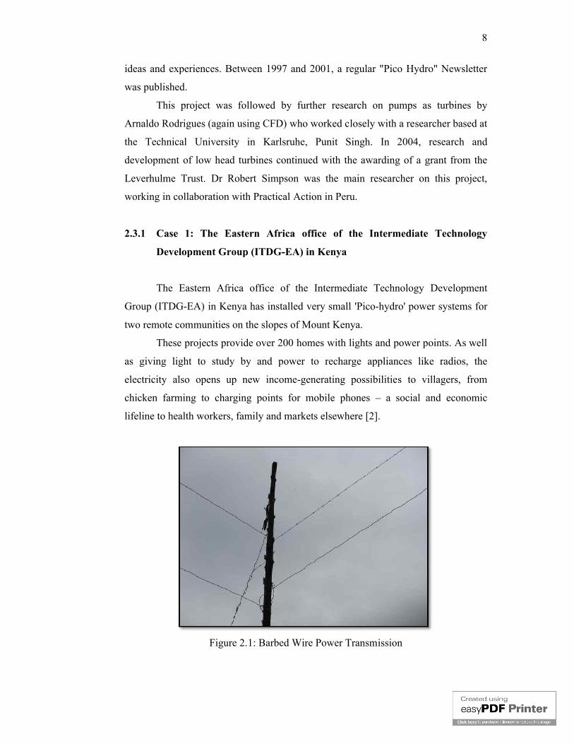
Figure 2.1: Barbed Wire Power Transmission
ideas and experiences. Between 1997 and 2001, a regular "Pico Hydro" Newsletter
This project was followed by further research on pumps as turbines by
Arnaldo Rodrigues (again using CFD) who worked closely with a researcher based at
the Technical University in Karlsruhe, Punit Singh. In 2004, research and
development of low head turbines continued with the awarding of a grant from the
Leverhulme Trust. Dr Robert Simpson was the main researcher on this project,
working in collaboration with Practical Action in Peru.
Case 1: The Eastern Africa office of the Intermediate Technology
Development Group (ITDG-EA) in Kenya
The Eastern Africa office of the Intermediate Technology
EA) in Kenya has installed very small 'Pico-hydro' power systems for
two remote communities on the slopes of Mount Kenya.
These projects provide over 200 homes with lights and power points. As well
as giving light to study by and power to recharge appliances like radios, the
electricity also opens up new income-generating possibilities to villagers, from
chicken farming to charging points for mobile phones – a social and economic
lifeline to health workers, family and markets elsewhere [2].
Figure 2.1: Barbed Wire Power Transmission
8
ideas and experiences. Between 1997 and 2001, a regular "Pico Hydro" Newsletter
This project was followed by further research on pumps as turbines by
who worked closely with a researcher based at
the Technical University in Karlsruhe, Punit Singh. In 2004, research and
development of low head turbines continued with the awarding of a grant from the
rcher on this project,
Case 1: The Eastern Africa office of the Intermediate Technology
The Eastern Africa office of the Intermediate Technology Development
hydro' power systems for
These projects provide over 200 homes with lights and power points. As well
ower to recharge appliances like radios, the
generating possibilities to villagers, from
a social and economic
Page 17
The schemes’ size and design avoid environmental disruption while
providing a cheaper and safer alternative to kerosene and lead
Equally important is ITDG’s success in bringing about
in Kenya to help create a decentralized electricity market, allowing micro
such as these to thrive countrywide.
The schemes’ size and design avoid environmental disruption while
providing a cheaper and safer alternative to kerosene and lead-based dry cells.
Equally important is ITDG’s success in bringing about a proposed change of policy
in Kenya to help create a decentralized electricity market, allowing micro
such as these to thrive countrywide.
Figure 2.2: Pico Hydro Station
Figure 2.3: Pico Hydro System
9
The schemes’ size and design avoid environmental disruption while
based dry cells.
a proposed change of policy
in Kenya to help create a decentralized electricity market, allowing micro-schemes
Page 18
2.3.2 Case 2: A Pico Hydro Power Plant f
In December 2006, RIDS
made by NHE (Nepal Hydro Electric) in Butwal
water flow of 27 liter per second and a negative head of 5 meter ("negative" because
the "head" is not "in front" of the turbine providing pressure, but after the turbine
producing a vacuum through a conical shaft, and thus
the turbine).
Another challenge was to install the Pico without any cement, as in a place
like Humla where all materials have to be carried in for 15 days from the next road
head, or flown in by plane, material becomes unaffor
people. Thus as much as possible only local material, which means stone, wood and
mud can be used for the dam, the canal and the power house.
RIDS-Nepal installed the Plant in Kholsi
Longitude: 81°45.24.00" East / Altitude: 2515 meter above sea level, 745 mbar
pressure at 20°C). Kholsi has a good hydro resource with a river flowing just north
west of the village. Hydropower being the most sustainable and
renewable resource, the
700m from the village in North East direction.
Case 2: A Pico Hydro Power Plant for Elementary Lighting in Nepal
In December 2006, RIDS-Nepal installed the first Pico Power Plant prototype
made by NHE (Nepal Hydro Electric) in Butwal, producing 650 Watt power by a
water flow of 27 liter per second and a negative head of 5 meter ("negative" because
the "head" is not "in front" of the turbine providing pressure, but after the turbine
producing a vacuum through a conical shaft, and thus "sucking" the water through
Another challenge was to install the Pico without any cement, as in a place
like Humla where all materials have to be carried in for 15 days from the next road
head, or flown in by plane, material becomes unaffordable expensive for the local
people. Thus as much as possible only local material, which means stone, wood and
mud can be used for the dam, the canal and the power house.
Figure 2.4: Inside Generation Station
Nepal installed the Plant in Kholsi village (30°00'25.77" North /
Longitude: 81°45.24.00" East / Altitude: 2515 meter above sea level, 745 mbar
pressure at 20°C). Kholsi has a good hydro resource with a river flowing just north
west of the village. Hydropower being the most sustainable and locally available
renewable resource, thePico-hydro plant was installed at the river which is about
700m from the village in North East direction.
10
or Elementary Lighting in Nepal
Nepal installed the first Pico Power Plant prototype
, producing 650 Watt power by a
water flow of 27 liter per second and a negative head of 5 meter ("negative" because
the "head" is not "in front" of the turbine providing pressure, but after the turbine
"sucking" the water through
Another challenge was to install the Pico without any cement, as in a place
like Humla where all materials have to be carried in for 15 days from the next road
dable expensive for the local
people. Thus as much as possible only local material, which means stone, wood and
village (30°00'25.77" North /
Longitude: 81°45.24.00" East / Altitude: 2515 meter above sea level, 745 mbar
pressure at 20°C). Kholsi has a good hydro resource with a river flowing just north-
locally available
hydro plant was installed at the river which is about
Page 19
Figure 2.5: Generator While Operating
From June 2000, RIDS
Nepal got sponsored from the Calgary University in Canada. A survey and
estimation was done for 67 houses in Kholsi, two to three lights of 9 WLEDs per
household, total 200 lights.
Due to the enormous deforestat
wires underground. That helps save the soft pine
protected from the monsoon rains, the snow in the winter and the storms in spring
time. It is more costly initially, but that pa
maintenance needed for years to come.
As a Pico produces
flowing through the wires. After 1 years running, the Pico was providing nonstop
light, very few minor break downs in the un
easily be handle and repair
Figure 2.5: Generator While Operating
From June 2000, RIDS-Nepal begins to make WLEDs lights, which RIDS
Nepal got sponsored from the Calgary University in Canada. A survey and
estimation was done for 67 houses in Kholsi, two to three lights of 9 WLEDs per
household, total 200 lights. The total power consumption is 650 Watts.
Due to the enormous deforestation problems in Humla, RIDS-Nepal puts all
wires underground. That helps save the soft pine wood the wires are also much better
protected from the monsoon rains, the snow in the winter and the storms in spring
time. It is more costly initially, but that pays off quickly, as there is hardly any
maintenance needed for years to come.
As a Pico produces just 650 Watt by 220 Volt AC, it just produces
flowing through the wires. After 1 years running, the Pico was providing nonstop
or break downs in the underground wire occurred which can
handle and repair.
11
Nepal begins to make WLEDs lights, which RIDS-
Nepal got sponsored from the Calgary University in Canada. A survey and
estimation was done for 67 houses in Kholsi, two to three lights of 9 WLEDs per
Nepal puts all
the wires are also much better
protected from the monsoon rains, the snow in the winter and the storms in spring
ys off quickly, as there is hardly any
produces 4.5 Amps
flowing through the wires. After 1 years running, the Pico was providing nonstop
derground wire occurred which can
Page 20
2.4 Component of Pico Hydro S
There are eight main components to a Pico Hydro S
1. Water supply, tank and penstock
2. Turbine
3. Generator
4. Charging circuit
5. Battery
6. Inverter
7. Distribution system
8. Electrical loads
Figure 2.7 shows Pico Hydro Power S
water supply from a spring or small canal to move the turbine.
Figure 2.6: WLEDs lights
of Pico Hydro System
ight main components to a Pico Hydro System:
Water supply, tank and penstock
ystem
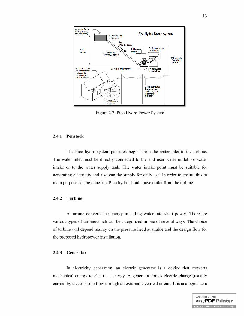
Figure 2.7 shows Pico Hydro Power System used in Kenya. They utilize
water supply from a spring or small canal to move the turbine.
12
ystem used in Kenya. They utilize
Page 21
Figure 2.7: Pico Hydro Power System
2.4.1 Penstock
The Pico hydro system penstock begins from the water inlet to the turbine.
The water inlet must be directly connected to the end user water outlet for water
intake or to the water supply tank. The water intake point must be suitable for
generating electricity and also can the supply for daily use. In order to ensure this to
main purpose can be done, the Pico hydro should have outlet from the turbine.
2.4.2 Turbine
A turbine converts the energy in falling water into shaft power. There are
various types of turbinewhich can be categorized in one of several ways. The choice
of turbine will depend mainly on
the proposed hydropower installation.
2.4.3 Generator
In electricity generation, an electric generator is a device that converts
mechanical energy to electrical energy. A generator forces electric charge (usually
carried by electrons) to flow through an external electrical circuit. It is analogous to a
Figure 2.7: Pico Hydro Power System
The Pico hydro system penstock begins from the water inlet to the turbine.
The water inlet must be directly connected to the end user water outlet for water
intake or to the water supply tank. The water intake point must be suitable for
ting electricity and also can the supply for daily use. In order to ensure this to
main purpose can be done, the Pico hydro should have outlet from the turbine.
A turbine converts the energy in falling water into shaft power. There are
ious types of turbinewhich can be categorized in one of several ways. The choice
f turbine will depend mainly on the pressure head available and the design flow for
the proposed hydropower installation.
In electricity generation, an electric generator is a device that converts
mechanical energy to electrical energy. A generator forces electric charge (usually
carried by electrons) to flow through an external electrical circuit. It is analogous to a
13
The Pico hydro system penstock begins from the water inlet to the turbine.
The water inlet must be directly connected to the end user water outlet for water
intake or to the water supply tank. The water intake point must be suitable for
ting electricity and also can the supply for daily use. In order to ensure this to
main purpose can be done, the Pico hydro should have outlet from the turbine.
A turbine converts the energy in falling water into shaft power. There are
ious types of turbinewhich can be categorized in one of several ways. The choice
the pressure head available and the design flow for
In electricity generation, an electric generator is a device that converts
mechanical energy to electrical energy. A generator forces electric charge (usually
carried by electrons) to flow through an external electrical circuit. It is analogous to a
Page 22
water pump, which causes water to flow (but does not create water). The source of
mechanical energy may be a reciprocating or turbine steam engine, water falling
through a turbine or waterwheel, an internal combustion engine, a wind turbine, a
hand crank, compressed air or any other source of mechanical energy.
2.4.4 Battery
Rechargeable battery (also known as a storage battery) is a group of one or
more secondary cells. Rechargeable batteries use electrochemical reactions that are
electrically reversible. Re
different combinations of chemicals. A charge controller circuit needed to control the
charging and discharging process of
graphical picture of charging an
active material is oxidized, producing electrons, and the negative material is reduced,
consuming electrons. These electrons constitute the current flow in the external
circuit. The electrolyte may serve
electrodes, as in lithium
participant in the electrochemical reaction, as in lead
Figure 2.8:
pump, which causes water to flow (but does not create water). The source of
mechanical energy may be a reciprocating or turbine steam engine, water falling
through a turbine or waterwheel, an internal combustion engine, a wind turbine, a
ssed air or any other source of mechanical energy.
Rechargeable battery (also known as a storage battery) is a group of one or
more secondary cells. Rechargeable batteries use electrochemical reactions that are
electrically reversible. Rechargeable batteries come in many different sizes and use
different combinations of chemicals. A charge controller circuit needed to control the
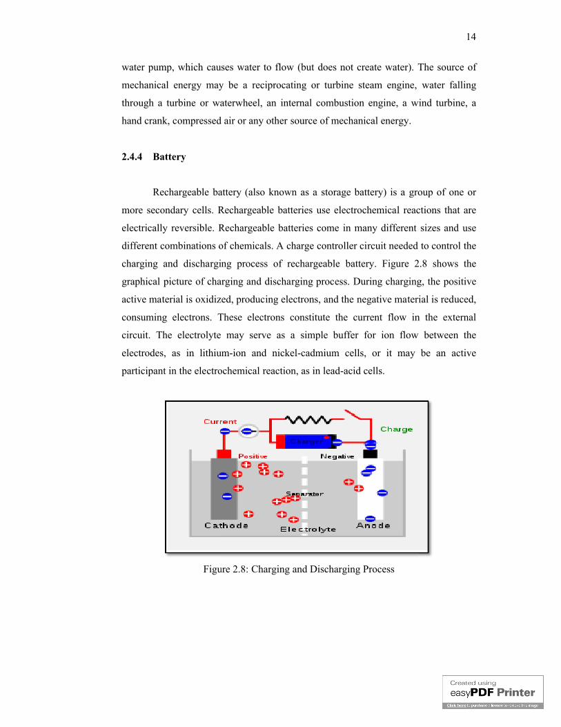
charging and discharging process of rechargeable battery. Figure 2.8
graphical picture of charging and discharging process. During charging, the positive
active material is oxidized, producing electrons, and the negative material is reduced,
consuming electrons. These electrons constitute the current flow in the external
circuit. The electrolyte may serve as a simple buffer for ion flow between the
electrodes, as in lithium-ion and nickel-cadmium cells, or it may be an active
participant in the electrochemical reaction, as in lead-acid cells.
Figure 2.8: Charging and Discharging Process
14
pump, which causes water to flow (but does not create water). The source of
mechanical energy may be a reciprocating or turbine steam engine, water falling
through a turbine or waterwheel, an internal combustion engine, a wind turbine, a
Rechargeable battery (also known as a storage battery) is a group of one or
more secondary cells. Rechargeable batteries use electrochemical reactions that are
chargeable batteries come in many different sizes and use
different combinations of chemicals. A charge controller circuit needed to control the
rechargeable battery. Figure 2.8 shows the
d discharging process. During charging, the positive
active material is oxidized, producing electrons, and the negative material is reduced,
consuming electrons. These electrons constitute the current flow in the external
as a simple buffer for ion flow between the
cadmium cells, or it may be an active
Page 23
15
2.4.5 Inverter
A power inverter is a DC to AC inverter device that is capable of turning DC
power, like the power found in batteries or the kind collected from generator, into
AC power that is used to run everyday things in the home such as appliances,
electronics, and even household lighting.
2.4.6 Distribution system
The distribution system connects the electricity supply from the generator to
the room. This is often one of the most expensive parts of the system.
2.4.7 Electrical loads
Electrical loads are usually connected inside houses. This is a general name
given to any device that uses the electricity generated. The type of loads connected to
a Pico hydro scheme depends largely on the amount of power generated. Using the
power wisely can add more benefits. Special lights such a fluorescent bulb, for
example, use less power and so more lights can be connected to the same generator.
2.5 Pico Hydro System Planning
The most important part for this project is planning as install ability in
resident house. There are many factors that determine the suitability of the system.
This includes:
1. The amount of power available from water flow in the pipelines. This includes
water
pressure, volume of water available and friction losses in the pipelines.
2. The type of turbine and available generator type and capacity.
3. The type and capacity of loads to be supplied by the Pico Hydro.
4. The cost of developing the project and operating the system.
Page 24
16
Figure 2.9 shows the procedure to plan a Pico Hydro system.
Figure 2.9: Pico Hydro System Planning
2.5.1 Power estimation
Potential energy is a kind of stored energy and the energy of position. The
water in a water tank on top of a house is example of potential energy [6]. The stored
energy in the tank is converted into kinetic energy (motion) as the water flows down
a large pipe call penstock and spin the turbine. The turbine spins a shaft inside the
generator, where magnets and coils of wire convert the motion energy into electrical
energy through a phenomenon called electromagnetism.
Power Estimation
Water Flow Rate Measurement
Pipeline System and Fraction Loss
Selection of Turbine Type
Head Measurement
Selection of Generator
Inverter
Type of Loads
Page 25
17
These are the step of water flow:
1. Water in a tank on top of a house flows through a filter that filters dust or
sediment in the tank.
2. The water travel through a pipe called a penstock and been blast by high
pressure water jet.
3. The force of the water spins a turbine at a high speed.
4. Water flows out of the penstock.
2.5.2 Head measurement
Head rate is very important parameter in hydropower. It is a measure of
falling water at turbine which is calculated from begins of penstock to the turbine at
the bottom [4-5]. When determine head, we should observed static head first. This is
due to the fix high of water tank in our house. For most of resident house, the high of
water tank is 3-4 meter from ground.
2.5.3 Water flow rate measurement
In fluid dynamic studies, water flow rate is the volume of fluid which passes
through a given surface per unit time. The SI unit is m3 s-1 (cubic meters per second).
In US Customary Units and British Imperial Units, volumetric flow rate is often
expressed as ft3/s (cubic feet per second).
2.5.4 Pipeline system and friction loss
Pipeline system is used to carry water to a turbine. This is commonly termed
as penstock which consists of pipe from the reservoir or water tank and valve or
water gate that controls the water rate flows.
The generation of electricity for large hydroelectric begins with water
flowing from the reservoir into openings on the upstream side of dam to penstocks,
which are very large pipes. The water flows down the penstock to turbines at the
bottom, spin the turbine and generate power. The proposed Pico-hydro system will
Page 26
18
have the water source from consuming water distributed to houses so the system
must be designed with ability to produce high water pressure to rotate the turbine at
the most possible speed and at the same time, the water can be recycled and used for
routine activity. Water jet should be installed to the end of penstock so that the
turbine rotation speed can be maximized [3].
Friction loss refers to that portion of pressure lost by fluids while moving
through a pipe, hose, or other limited space. In mechanical systems such as internal
combustion engines, it refers to the power lost overcoming the friction between two
moving surfaces.
Friction loss has several causes, including:
1. Frictional losses depend on the conditions of flow and the physical properties
of the system.
2. Movement of fluid molecules against each other
3. Movement of fluid molecules against the inside surface of a pipe or the like,
particularly if the inside surface is rough, textured, or otherwise not smooth
4. Bends, kinks, and other sharp turns in hose or piping
In pipe flows the losses due to friction are of two kinds which are skin-
friction and form-friction. The former is due to the roughness of the inner part of the
pipe where the fluid comes in contact with the pipe material, while the latter is due to
obstructions present in the line of flow perhaps a bend, control valve, or anything
that changes the course of motion of the flowing fluid.
2.5.5 Selection of generator
In electricity generation, an electric generator is a device that converts
mechanical energy to electrical energy. A generator forces electric charge (usually
carried by electrons) to flow through an external electrical circuit.
Electric generators types depend on the type of generating equipment
employed, the electrical energy produced is either DC or AC.
AC generators are classified as single-phase or poly-phase. A single phase
generator is usually limited to 25kW or less and generates AC power at a specific
Page 27
19
utilization voltage. Poly-phase generators produce two or more alternating voltage
(usually two, three, or six phase).
DC generators are classified as shunt, series, or compound-wound. Most DC
is the compound-wound type. Shunt generators are usually used as battery chargers
and as exciters for AC generators. Series generators are sometimes used for street
direct the flow of current in one direction. The generator rotating commutators
provide the rectifying action [7].
Generating system for a hydro power scheme is selected based on the
following concerns:
1. The estimated power of a hydropower system
2. Type of supply system and electrical load: AC or DC
3. Available generating capacity in the market
4. Generator with cost effective
Normally, Pico hydro systems use AC generator either induction or
synchronous machine type. This is because the system is used to supply AC
electrical appliances and DC generator above 2kW is expensive and has brush gear
that required maintenance. Furthermore, DC switch for voltage and current is more
expensive then equivalent AC switch.
However, for storing energy purpose in batteries a brush permanent magnet
DC generator is preferred. One significant advantage of using DC type of permanent
magnet generator over AC generator is that DC generator is designed to provide high
currents at minimum voltage requirement for charging of battery and operation of
direct current loads. This is related with load type to be supplied. Moreover,
permanent magnet generator is selected as it is much cheaper and has smaller overall
size rather than of wound field. Other than that, this type of generator is more
efficient because no power is wasted to generate the magnetic field.
Page 28
2.5.6 Selection of turbine type
Selection of turbine to be used is very important in the design and
development of a hydropower system. In general, reaction turbine is fully immersed
in water and is enclosed in a pressure casing.
which converts the energy of flowing water into mechanical energy. The mechanical
energy is then converted into electricity by a generator. A typical hydropower plant
includes a dam, reservoir, penstocks (water conveying pipes), and a power house
which contains the turbine, generator and an electrical power substation.
project, Pelton type turbine is choose because this Pico Hydro system has low head
and high volume of water flow [8]. Figure 2.10 shows the operation of a Pelton type
turbine.
Generally for all hydro turbines,
P = ρ x g x H x Q x η
(2.1)
Where
P = power (W),
H = Head (m),
Q = flow rate (m
Selection of turbine type
Selection of turbine to be used is very important in the design and
development of a hydropower system. In general, reaction turbine is fully immersed
in water and is enclosed in a pressure casing. A hydropower Turbine is
which converts the energy of flowing water into mechanical energy. The mechanical
energy is then converted into electricity by a generator. A typical hydropower plant
includes a dam, reservoir, penstocks (water conveying pipes), and a power house
which contains the turbine, generator and an electrical power substation.
project, Pelton type turbine is choose because this Pico Hydro system has low head
and high volume of water flow [8]. Figure 2.10 shows the operation of a Pelton type
Figure 2.10: Pelton Wheel Turbine
Generally for all hydro turbines,
(m3/s),
20
Selection of turbine to be used is very important in the design and
development of a hydropower system. In general, reaction turbine is fully immersed
A hydropower Turbine is a device
which converts the energy of flowing water into mechanical energy. The mechanical
energy is then converted into electricity by a generator. A typical hydropower plant
includes a dam, reservoir, penstocks (water conveying pipes), and a power house
which contains the turbine, generator and an electrical power substation. In this
project, Pelton type turbine is choose because this Pico Hydro system has low head
and high volume of water flow [8]. Figure 2.10 shows the operation of a Pelton type
Page 29
21
g = acceleration due to gravity (m/s2),
η = coefficient of efficiency,
ρ=density of water (kg/m3)
ρ strictly for Pelton hydro turbine,
P = ρ x Q x c x (u-c) x (1+K x cos θ) (2.2)
Where
ρ = water density,
u = absolute water velocity at inlet,
K = coefficient of friction 0.85,
θ = relative water angle at inlet (15o)
2.5.7 Inverter
A power inverter transfers readily available DC power, like from a battery or
other stored power source, and turns it into readily usable AC power on the go or at
home on devices you would normally plug into a home electrical outlet [13-15].
It is a good idea to add up the wattage used in the home normally by the
amount of wattage used in each appliance and electrical item, lighting, etc., and then
also give extra wattage for startups and occasional surges that many appliances tend
to put out at times. So the amount of wattage in all electrical items give out plus
some additional wattage for surges and startups should indicate a close enough
measure of the size of power inverter DC to AC needed. Remember that having
excess power is much better than having a brown out because it will deplete all of the
available power.
The batteries that connect to the inverter should be kept in fairly close
proximity to the power DC to AC inverter so that the cables can be short and run a
clean and clear signal. Power inverters are not weatherproof and should be kept from
getting wet. It should be kept dry like any other electronic device seeing as wetness
will destroy the device and cause an unsafe situation.
Deep cycle batteries are highly recommended and most often used with
power inverters because they tend to maintain a consistent voltage more efficiently,
are longer lasting than conventional batteries, they work well in extreme weather
Page 30
22
conditions, and they deliver a higher capability of amp surge than a conventional
battery ever could carry.
2.6 Conclusion
As conclusion for literature review and previous study, research of renewable
energy should be continue and expand from rural area to resident area. Several
aspects should be count in before installing Pico Hydro Generation system in
residential area especially house. Water pressure from selected source should be
measured in order to estimate output power. It also helps to choose right turbine,
generator, and maximum load can be support by the system.
In this Pico Hydro project, it is decided to use Pelton wheel for turbine,
Denso branded car alternator as generator, 12 volts 5 amperes battery as battery
bank, 12 volts charger controller, an inverter that converts 12volts DC to 240 volts
AC and a three pin socket outlet.
Page 31
23
CHAPTER 3
METHODOLOGY
3.1 Introduction
Methodology is a flow of actions which is taken in designing and developing
the project. The process includes design, analysis, implant, and getting the expected
result. There are two parts, which is research work and project development. First
and foremost, research is made related to the project and problems occur. The next
step is designing electronic circuit using PROTEUS and MULTISIM software and
designing prototype using Google Sketch Up software.
This stage is the most critical stage in research as it determines the feasibility
and achievability of the proposed Pico Hydro Generation system. There are factors
that influence the feasibility and achievability of the system. This includes:
i. Amount of power available from the water flow inside the pipeline. This
depends on the water pressure, amount of water available and friction loss in
the pipeline.
ii. Turbine type and the availability of required generator type and capacity.
iii. Type and capacity of electrical load to be supplied by the Pico Hydro
Generation system.
iv. Cost of developing the project and operating the system.
Page 32
3.2 Power Estimation
There are three types of powerIn Pico Hydro power system. All of these
power are related to each other, however only one power is needed. The first kind of
power is known as hydraulic power or water power, which comes from the water
flow in the channel. Second type of power comes from the rotating turbine, known as
mechanical power. The third type which is the one that is needed by consumer is
electrical power. Electrical power is produced when the generator or in this case, car
alternator operates.
Power could not be created nor be destroyed. All it can do is converting to
another type of power. In this project, the water power (or hydraulic power) will
always be more than the mechanical and electrical power. This is because as the
power is converted from one form to another, some is lost at each stage as shown in
Figure 3.1.
Figure
Usually, on a well designed Pico Hydro Generation system approximately
one third of the power of the nozzle will be
the generator when mechanical power is converted to electricity. After all, there are
four steps involved during this power conversion. Only electrical power will be
considered in the design.
ower Estimation
There are three types of powerIn Pico Hydro power system. All of these
power are related to each other, however only one power is needed. The first kind of
power is known as hydraulic power or water power, which comes from the water
in the channel. Second type of power comes from the rotating turbine, known as
mechanical power. The third type which is the one that is needed by consumer is
electrical power. Electrical power is produced when the generator or in this case, car
Power could not be created nor be destroyed. All it can do is converting to
another type of power. In this project, the water power (or hydraulic power) will
always be more than the mechanical and electrical power. This is because as the
is converted from one form to another, some is lost at each stage as shown in
Figure 3.1: Power Loss during Conversion
Usually, on a well designed Pico Hydro Generation system approximately
one third of the power of the nozzle will be lost. A further 20% to 30% will be lost in
the generator when mechanical power is converted to electricity. After all, there are
four steps involved during this power conversion. Only electrical power will be
considered in the design.
24
There are three types of powerIn Pico Hydro power system. All of these
power are related to each other, however only one power is needed. The first kind of
power is known as hydraulic power or water power, which comes from the water
in the channel. Second type of power comes from the rotating turbine, known as
mechanical power. The third type which is the one that is needed by consumer is
electrical power. Electrical power is produced when the generator or in this case, car
Power could not be created nor be destroyed. All it can do is converting to
another type of power. In this project, the water power (or hydraulic power) will
always be more than the mechanical and electrical power. This is because as the
is converted from one form to another, some is lost at each stage as shown in
Usually, on a well designed Pico Hydro Generation system approximately
lost. A further 20% to 30% will be lost in
the generator when mechanical power is converted to electricity. After all, there are
four steps involved during this power conversion. Only electrical power will be
Page 33
[1] N. Smith and G. Ranjitkhar, “Nepal Case Study–Part One: Installation and
performance of the Pico Power Pack,” Pico Hydro Newsletter, April 2000.
[2] P. Maher. “Kenya Case Study 1 at Kathamba and Case Study 2 at Thima.”
Available at: http://www.eee.nottingham.ac.uk/picohydro/documents.html#kenya
[3] P. Maher and N. Smith, “Pico hydro for village power: A practical manual for
schemes up to 5 kW in hilly areas,” 2nd ed., Intermediate Technology
Publications, May 2001.
[4] J. Mariyappan, S. Taylor, J. Church and J. Green, “A guide to CDM and family
hydropower,” Final technical report for project entitled Clean Development
Mechanism (CDM) project to stimulate the market for family-hydro for low
income families, IT Power, April 2004.
[5] A. Williams, “Pico hydro for cost - effective lighting”, Boiling Point Magazine,
pp. 14-16, May 2007.
[6] H. Zainuddin, M. S. Yahaya, J. M. Lazi, M. F. M. Basar and Z. Ibrahim, “Design
and Development of Pico-hydro Generation System ForEnergy Storage Using
Consuming WaterDistributed to Houses”, International Conference on Computer,
Electrical, and Systems Science, and Engineering 2009 (CESSE '09) at Bali,
Indoneisa, 25-27 November 2009.
[7] Wind stream Power, Permanent Magnet Dc Generator, [online]. Available at:
http://www.windstreampower.com/443540_PMDCG.php
[8] A. Harvey, A. Brown, P. Hettiarachi and A. Inversin, ‘Micro hydro design
manual: A guide to small-scale water power schemes,’ Intermediate Technology
Publications, 1993.
Page 34
[9] Zahnd, A., Kimber, H. M., Benefits from a renewable energy village
electrification system, Renewable Energy, Vol. 34, 2009, pp. 362-368.
[10] A.A. William, R. Simpson, Pico-hydro – Reducing Technical risks for rural
electrification, Renewable Energy, Vol. 34, 2009, pp. 1986-1991.
[11] Baines J., William A.A., A test rig for pico hydro Pelton turbines. Pico Hydro,
issue 1. UK: Nottingham Trent University; Oct 1997.
[12] Kamaruzzaman Sopian, Juhari Ab. Razak, Pico Hydro: Clean Power fromSmall
Streams. Proceedings of the 3rd WSEAS Int. Conf on Renewable Energy, 2009,
pp. 414-419.
[13] M. H. Rashid, "Power Electronics Circuits, Devices, and Applications,” Prentice
Hall of India Private Limited, New Delhi, Second Edition, 1996.
[14] 600 Watt Pure Sine Wave Inverter. Donrowe.com. Retrieved December 14,
2006 [online]. Available at:
http://www.donrowe.com/inverters/puresine_600.html.
[15] ABS Alaskan. (2006). DC to AC Power Inverters. Retrieved December 4, 2006
[online]. Available at: http://www.absak.com/basic/inverters.html.