NRC015 Submitted: 8/25/2014 -1- United States Nuclear Regulatory Commission Official Hearing Exhibit In the Matter of: STRATA ENERGY, INC. (Ross In Situ Recovery Uranium Project) ASLBP #: 12-915-01-MLA-BD01 Docket #: 04009091 Exhibit #: Identified: Admitted: Withdrawn: Rejected: Stricken: Other: NRC015-00-BD01 9/30/2014 9/30/2014 Groundwater and Wells Second Edition A comprehensive study of groundwater and the technologies used to locate, extract, treat, and protect this resource. Pruction well Observation well ; . . . Cone of depression · Drawdown curve · Pmplng water level ' · . . .. .· . . . . . . . . . . . .
Transcript
NRC015 Submitted: 8/25/2014
-1-
Uni
ted
Stat
es N
ucle
ar R
egul
ator
y C
omm
issi
on O
ffici
al H
earin
g Ex
hibi
t
In th
e M
atte
r of:
STR
ATA
EN
ER
GY,
INC
. (R
oss
In S
itu R
ecov
ery
Ura
nium
Pro
ject
)
ASL
BP
#:
12-9
15-0
1-M
LA-B
D01
D
ocke
t #:
0400
9091
Ex
hibi
t #:
Id
entif
ied:
A
dmitt
ed:
W
ithdr
awn:
R
ejec
ted:
Stric
ken:
O
ther
: N
RC
015-
00-B
D01
9/30
/201
49/
30/2
014
Groundwater and
Wells Second Edition
A comprehensive study of groundwater and the technologies used to locate, extract, treat,
Printed in the United States of America. All rights reserved. This book. or parts thereof. may not be reproduced without written permission from the publisher.
II. M. Smyth Company. Inc. printed this volume on Mead Corporation's sixty pound Moistrite stock. Typography was done by CTS Inc.; the text was set in 9 point Times Roman type face.
The information and recommendations contained in this book have been compiled from sources believed to be reliable and to represent the best opinion on the s~;~bject as of 1986. However, no warranty, guarantee, or representation. express or implied. is made by Johnson Screens as to the correctness or sufficiency of this information or to the results to be obtained from the use thereof. It cannot be assumed that all necessary warnings. safety suggestions, and precautionary measures arc contained in this book, or that any additional information or measures ma) not be required or desireable because of particular conditions or circumstances, or because of any applicable U.S.A. federal. state, or local law. or any applicable foreign law or any insurance rcquircmenfs or codes. The warnings. safety suggestions, and precautionary measures contained herein do not supplement or modify any U.S.A. federal, state, or local law, or any applicable foreign law, or any insurance requirements or codes.
II
-2-
California Stovepipe Method Direct Rotary Drilling . . Drilling Fluids . . . . . Reverse Circulation Rotary Drilling Air Drilling Systems . . . . . . In-Verse Drilling . . . . . . . Dual-Wall Reverse Circulation Rotary Method . Drill-Through Casing Driver . Jet Drilling . . . . . . . Hydraulic-Percussion Method Boring with Earth Augers . . Driven Wells . . . . . . Drilling Procedures When Boulders are Encountered Fishing Tools . . . . . . . Grouting and Sealing Well Casing Plumbness and Alignment .
Chapter 11. Drilling Fluids Types of Drilling Fluids Functions of a Drilling Fluid Properties of Water-Based Drilling Fluids Treatment of Mix Water for Drilling Fluids Mixing Additives into Water-Based Systems . Air Drilling . . . . . . . . . . . . Drilling Fluid Additives . . . . . . . Guidelines for Solving Specific Drilling Fluid Problems Typical Drilling Problem . . . . . . . . . .
Chapter 12. Well Screens and Methods of Sediment-Size Analysis
Continuous-Slot Screen . . Other Types of Well Screens Sediment-Size Analysis . .
Chapter 13. Water Well Design Casing Diameter Casing Materials . Well Depth . . . Well Screen Length Well Screen Slot Openings . Pressure-Relief Screens Formation Stabilizer . Well Screen Diameter Open Area . . . . Entrance Velocity . . Screen Transmitting Capacity Selection of Material
Design of Domestic Wells . . Design for Sanitary Protection Special Well Designs
Chapter 14. Installation and Removal of Well Screens Pull-Back Method Open-Hole Methods for Screen Installation Filter Packed Wells . . . . Installation of Plastic Screens . Bail-Down Procedure Wash-Down Method Jetting Method Installing Well Points Removing Well Screens
Chapter 15. Development of Water Wells Well Development . . . . Factors that Affect Development Well Development Methods . . A Comparison ofThree Development Methods Use of Polyphosphates in Development . . . Development of Rock Wells . . . . . . . Allowable Sediment Concentration in Well Water . Aquifer Development Techniques . . . . . .
Chapter 16. Collection and Analysis of Pumping Test Data Conducting a Pumping Test . Measuring Drawdown in Wells Well Efficiency . . . . . Step-Drawdown Tests Problems of Pumping Test Analysis
Chapter 17. Water Well Pumps Variable Displacement Pumps Positive Displacement Pumps Pumps Used to Circulate Drilling Fluid Air-Lift Pumping . Pump Selection Water Storage . .
Chapter 18. Water-Quality Protection for Wells and Nearby Groundwater Resources . . . . . .
Choosing a Well Site . . . . . . . . . . Predicting the Pollution Potential at a Drilling Site Well Design . . . . . . . . . . .
xii
458 460 461
464 464 472 476 483 485 487 489 491 492
497 497 499 502 521 522 523 526 528
534 535 547 554 555 559
580 581 604 606 608 608 610
612 614 616 617
-4-
278 GROUNDWATER AND WELLS
installed by the pull-back method. The hydraulic jacks that pull down the casing in the stovepipe method can then be reversed to pull back the casing.
DIRECT ROTARY DRILLING
The direct rotary drilling method was developed to increase drilling speeds and to reach greater depths in most formations (Figure 10.11). The borehole is drilled by rotating a bit, and cuttings are removed by continuous circulation of a drilling fluid as the bit penetrates the formation. The bit is attached to the lower end of a string
Canier
Hydraulic
reservoir
Hydraulic cylinders
injection
system
Traveling
blocks
Figure 10.1 1. &hematic diagram of a direct rotary rig illustrates the important operational components of this truck-mounted drilling machine. This machine, operating "ith either an air-based or water-based drilling nuid, can drill more npidly than a cable tool rig. (Gardner-Denl'er Company)
-5-
WELL DRILLI 'G METHODS 279
of drill pipe, which transmits the rotating action from the rig to the bit. In the direct rotary system, drilling fluid is pumped down through the drill pipe and out through the ports or jets in the bit; the fl uid then flows upward in the annular space between the hole and drill pipe, carrying the cuttings in suspension to the surface. At the surface, the fluid is channeled into a settling pit or pits where most of the cuttings drop out. Clean fluid is then picked up by the pump at the far end of the pit or from the second pit and is recirculated down the hole (Figure I 0.12). For relatively shallow wells, 150- to 500-gal (0.6- to 1.9-m ')portable pits may be used; much larger portable pits, I 0,000 to 12,000 gal (37. 9 to 45.4 m3), are used for deeper wells. Mud pits may also be excavated for temporary use during drilling and then backfilled after completion of the well (sec Chapter II for various mud pit configurations).
Before 1920, the type of rotary drill used in water well drilling was commonly called a whirler. T his equipment used the well casing itself as the dri ll pipe. The lower end of the pipe was fi tted with a serrated cutt ing shoe with an outside diameter a little larger than the drill pipe couplings. The sawteeth of the shoe cut and loosened the materials as the pipe was rotated. Water was pumped under pressure through the pipe to lift the cutt ings to the surface. Native clays and silt were depended upon to seal the borehole wall to maintain circulation: prepared drilling fluids were not used. The method was suitable for drilling only relatively small-diameter, shallow wells in unconsolidated formations that did not contain cobbles or boulders.
In the 1930's, shot-hole rotary drills, used for seismograph work in oil exploration, were successfully adapted for drilling small-diameter water wells. Shot-hole machines, however, could not drill the large-diameter holes necessary for water well work because the mud pump and drill pipe were generally too small to circulate enough drilling
Figure 10.12. Drilling fluid from the borehole flows into the larger pit where the cuttings settle out. The fluid then flows into the second pit through a constricted opening. The mud pump on the rig withdraws drilling fluid from this pit to inject down the drill rods to the bit. This Italian driller has lined the drilling fluid pits wi th pol) ethylene film to reduce fluid loss into the ground. Note the homemade hole cleaner or scratcher the driller uses to keep the borehole open during drilling.
-6-
280 GROUNDWATER AND WELLS
Figure I 0. I 3. Drag bits are used in rotary drilling for fast penetration in unconsolidated or semiconsolidated sediments.
fluid to efficiently drill even an 8-in (203-mm) well. In time, truck-mounted portable rigs for drilling large-diameter water wells were developed from oil field exploration technology.
The components of the rotary drilling machine are designed to serve two functions simultaneously: operation of the bit and continuous circulation of the drilling fluid. Both are indispensable in cutting and maintaining the borehole. For economic and efficient operation, rotary drillers must acquire considerable knowledge concerning these factors and how they relate to various formation conditions.
In direct circulation rotary drilling for water wells, two general types of bits are used - the drag bit (fishtail and threeand six-way designs) and the roller cone bit, usually called a rock bit. Drag bits have short blades, each forged to a cutting edge and faced with durable metal (Figure 10.13). Short nozzles direct jets of drilling fluid down the faces of the blades to clean and cool them. Drag bits have a shearing action and cut rapidly in sands, clays, and some soft rock formations, but they do
not work well in coarse gravel or hard-rock formations. Roller (cone) bits exert a crushing and chipping action, making it possible to cut
hard formations (Figure I 0.14 ). The rollers, or cutters, are made with either hardened steel teeth or tungsten carbide inserts of varied shape, length, and spacing, designed so that each tooth applies pressure at a different point on the bottom of the hole as the cones rotate. The teeth of adjacent cones intermesh so that self-cleaning occurs. Long, widely spaced teeth are used in bits designed to cut soft clay formations, whereas shorter, closer spaced teeth are used for denser formations. Some roller bits are made with carbide buttons for particularly dense and abrasive formations such as dolomite, granite, chert, basalt, and quartzite.
The tricone bit, used as an all-purpose bit in every type of formation, has conically shaped rollers on spindles and bearings set at an angle to the axis of the bit. Another design has four rollers; two are set at an angle and two are normal to the vertical axis of the bit. The cutting surfaces of all roller bits are flushed by jets of drilling fluid directed from the inside (center) of the bit. The jets can be sized so as to maximize the cutting action of the bit. The jets are also effective in breaking up or washing away soft formation materials.
When hole enlargement becomes necessary, two other types of bits are used -reamers and underreamers (Figure I 0.1 5). A reamer is used to straighten, clean, or
-7-
WELL DRILLING METHODS 281
enlarge a borehole. This tool sometimes consists of a I 0- to 20-ft (3- to 6.1-m} section of drill pipe with specially hardened surfaces on vertical ribs. Other types of reamers are constructed of flanges welded on short sections of drill pipe and mounted between the bit and the stabilizer. In the underreaming process, the borehole diameter is enlarged beneath the permanent casing. Underreamers arc particular!} useful >Nhcn a filter pack must be placed around a screen, but the cost of drilling the entire borehole at the larger diameter required for the filter pack would be prohibitive.
The bit is attached to the lower end of the drill pipe, which resembles a long tubular shaft. The drill string usually consists of four parts: the bit, one or more drill collars or stabilizers, one or more lengths of drill pipe. and. in table-drive machines. the kelly (Figure I 0.16). Selection of the bottomhole assembly will depend on the physical conditions of the geologic materials; these include dip of the formation, presence of faults or fractures, and drillability of the formation.
Each drill collar is a heavy-walled length of drill pipe; one or more drill collars are used to add weight to the lower part of the dnll-stem assembly (Figure I 0.17). The concentration of weight just above the bit helps to keep the hole straight, and provides sufficient weight for the bit to maintain the proper penetration rate. Drill collars fitted with stabilizer bars or rollers are even more effective in drilling straight boreholes. Table 10.1 presents representative data on recommended sizes of drill collars.
Stabilizers arc an important component of the bottom-hole tools (Figure 10.18). To be effective in maintaining straight holes in soft formations. the stabilizer must have large wall contact. Increased contact can be achieved by using stabilizers with longer and wider blades, or by using longer stabilizers. The flow of drilling fluid upward around the stabilizer must not be restricted too much. however, because cuttings may pack around the stabili1.cr. This leads to sticking and a possible loss of circulation if back pressure builds up. Weakening of the formation structure can also result from the pressure increase. Accumulation of cuttings around the stabilizer rna) also cause local zones of erosion in the bore-
Figure 10.14. Roller or cone-t)pe bit~ are preferred "hen drilling con~olidated rock. The number of teeth on each roller cone depends on the drilling difficult~. As the rock becomes harder and more difficult to drill, the bit should have more teeth on each cone. For particularly dense or abrasive formations. carbide buttons are used instead of teeth on the roller cone~. Roller cone bits are often con<;tructed in configurations that "ill enlar~te the borehole in stages as the bit pent>tratcs the formation. For the bit shown. the primar~ bit i~ 171,'2 in (445 mm) and the reamer is 22 in (559 mm).
...
-8-
282 GROL''IDW \ TER AND WELLS
hole wall. In relatively hard format ions, the stabilizer can perform satisfactorily wi th less wall contact.
Drill pipe is seamless tubing manufactured in joints that arc usually 20 ft (6.1 m) long. although other lengths are available. Each joint is equipped with a tool-joint pin on one end and a tool-joint box on the other (F igure I 0.19). Outside diameters of drill pipe used for direct rotary drilling generally range from 23fs to 6 in (60 to 152 mm). High circulation rates for drilling fluids in water well drilling require that the drill p ipe diameter be adequate to hold friction loss in the pipe to an acceptable level so as to reduce the power required for the pump. For efficient operation, the outside diameter of the tool joint should be about two-thirds the borehole diameter: this ratio may be impractical, however. for holes larger than 10 in (254 mm).
In table-drive machines, the kelly constitutes the uppermost section of the drill string column. It passes through and engages in the opening in the rotary table, which is driven by hydraulic or mechanical means (F igure I 0.20). T he outer shape of the
Table 10.1. Ideal Size Range for Drill Collars
H ole Casing Calculated ideal drill \PI drill collar su es n hich
s ize, in s iLe to be collar range, in fa ll in the ideal range, in run, in O D :\l in. ;\l ax.
10% 11.250* 10.125 10 133,4 103/4 9.750 11.250 91/4, 10, II 143,4 I P/4 8.750 12.000 9. 9112, 93!4, I 0, I I. 12t 17112 13'1s 11.250 13.375 12t 20 16 14.000 14.750 14t 24 18Ys 15.500 16.750 16t 26 20 16.000 19.500 16t
•tn these instances. the equation used to calculate the ideal minimum drill collar size produces an anomalously high value. See Woods and Lubinski ( 1954) for a complete discussion on how to determine the best collar size for a specific diameter borehole.
tNot API standard sue drill collar.
(Drilco, 1979)
-9-
WELL DRILLING METHODS 283
Figure 10.15. On the left, a three-tiered 48-in (1,220-mm) reamer bit has just been removed from the borehole. (Snider Drilling Ltd.) For soft sediments, underreamers (right) are constructed of blades that extend outward from the bit.
kelly may be square or hexagonal, or round with lengthwise grooves or flutes cut into the outside wall. Made about 3 ft (0.9 m) longer than one joint of drill pipe, the kelly has an inside bore that is usually smaller than that of the drill pipe because of the heavy wall thickness required. The square, hexagonal, or grooved circular section of the kelly works up and down through drive bushings in the rotary table. With the bushings properly in place around the kelly, the entire drill stem and bit are forced to turn with the rotary table. While rotating, the kelly slips down through the drive bushings to feed the bit downward as the hole is drilled. The lower end of the kelly is provided with a replaceable substitute joint (sub), called a "kelly saver," that connects to the drill pipe. The sub saves the tool joint on the kelly from excessive wear resulting from the screwing and unscrewing of innumerable sections of drill pipe. The upper end of the kelly connects to a swivel (by a left-hand threaded joint) that is suspended from a traveling block in the derrick (Figure 10.21). A heavy thrust bearing between the two parts of the swivel carries the entire weight of the drill string while allowing the drill pipe to rotate freely.
Some rotary drilling machines use a top-head drive to rotate the drill string (Figure 10.22). In this system, the rotational unit moves up and down the mast; energy is obtained from a hydraulic transmission unit powered by a motor-driven pump.
In both the rotary table and top-head drive mechanisms, the driller can determine the rotation speed depending on the resistance of the formation and the rate of penetration. For shallow boreholes of 200 to 400 ft (61 to 122 m), pull-down pressure may be applied to the bit. Down-hole pressures on the bit can be increased beyond
...
-10-
284 (jROU "fDWA TER AND WELLS
Kelly
Drill pipe
Drill pipe
Drill collar
Bit
_j Figure 10.16. The drill s tring for a direct rotary rig con~i~t~ of a bit, drill collar or stabili~:er, drill pipe, and kelly for table drive units.
the weight of the drill string by exerting a pull-down force derived from the weight of the drilling rig. The chain assemblies (or cables) on the mast are used to transfer part of the weight of the drilling rig to the drill string. Caution should be used to avoid excessive pull-down pressure (weight) because hole deflection (crooked holes) may result. To avoid crooked holes. many drillers will use drill collars that concentrate additional weight on the bit rather than exert pull-down pressure. Rotation speed is adjusted to the pull-down or existing pressures on the bit. In general, the higher the pressure on the bit, the slower the rotation should be. In most deep direct rotary boreholes, the driller must hold back (suspend) part of the drill string weight from the swivel so that the weight on the bit does not become excessive. In general, the driller may start holding back when the weight of the drill string exceeds I 0,000 lb (4,540 kg), although the exact figure depends on the bit being used. Bit manufacturers usually indicate the optimum pressure that an individual bit should exert against the formation for maximum cutting rates.
Adding drill rods (pipe) to the drill string or removing rods to change bits or take split-spoon or core samples is a major part of every rotary drilling operation. "Tripping in" and "tripping out" are the terms used to describe the process of running the bit into or pulling the bit from
the hole. Most newer drilling rigs have been designed to make this process as fast and automated as possible. With some new machines. it is possible to pull back a 20-ft (6.1-m) rod and remove it from the drill string in approximately 30 seconds. In general, top-head drive machines, especially those equipped with carousels (drill rod storage racks mounted on the mast), otTer an advantage in rod handling speed, although recent modifications in table-drive machines have enabled this type of rig to match the speed of the top-head drive rotaries.
When a rod is to be added, the swivel is just above the rotary table (in a tabledrive machine). Usually the driller will circulate the drilling fluid for a few minutes to make sure that most of the cuttings are out of the hole to prevent tlhe bit and drill string from sand-locking when the circulation is stopped to add a drill rod. The kelly is raised until the joint between the kelly sub and the uppermost drill rod is just
-11-
WELL DRILLING METHODS 285
above the drive table. Slips arc placed in the table to hold the drill string (Figure I 0.23). The kelly is then disconnected and placed out of the way momentarily. A sand li nc (cable) is joined to another rod section using a quick-release elevator (clamp). The rod is ho1sted into place above the rod held in the table and the two arc threaded together. usually with the aid of automatic pipe clamps. The slips are removed and the string is lowered b} the sand !inc until the top (tool-joint box) of the just-added drill rod is just above the table. The slips arc reinserted. the elevator is removed, and the kell) is rethreaded to the dnll string. After lowering the kelly into the drive table, drilling can continue.
In top-head drive machines. no kell) is required and therefore the bottom sub of the hydraulic drive motor is connected directly to the drill rod. Additional rods can be taken directly from a carousel by the top-head drive unit. If the machine is equipped w1th side storage racks, a sand line must be used to raise the drill rod into position.
Internal pressure created by the drilling Ouid can cause a momentary but forceful surge of drilling nu1d out oft he drill string at the point where the kelly is disconnected from the upper drill rod. Drillers usually break this joint slowly to allow the pressure to diss1pate so that drilling nu1d is not expelled violently. Occasionally during the addition of a drill rod. drilling nuid may continue to overflow from the top of the rods. Confining pressures within permeable material in the borehole may be causing this now, but it is more likely that clay "collars" packed around the drill rods are falling deeper into the borehole, thereby pushing drilling nuid back up the center of the rods. Direct rotary drilling, the most common method, offers the following advantages:
1. Penetration rates arc relatively high in all types of materials. 2. Mmimal casing is required during the drilling operation.
Figure 10.17. H eavy collars added to the drill s tring above the bit help keep the borehole straight.
-12-
286 GROUNDWATER AND WELlS
3. Rig mobilization and demobilization are rapid. 4. Well screens can be set easily as part of the casing installation.
Major disadvantages include the following: I. Drilling rigs are costly. 2. Drilling rigs require a high level of maintenance. 3. Mobility of the rigs may be limited depending on the slope and condition (wet-
ness) of the land surface. 4. Most rigs must be handled by a crew of at least two persons. 5. Collection of accurate samples requires special procedures. 6. Use of drilling fluids may cause plugging of certain formations. 7. Rigs cannot be operated economically in extremely cold temperatures. 8. Drilling fluid management requires additional knowledge and experience.
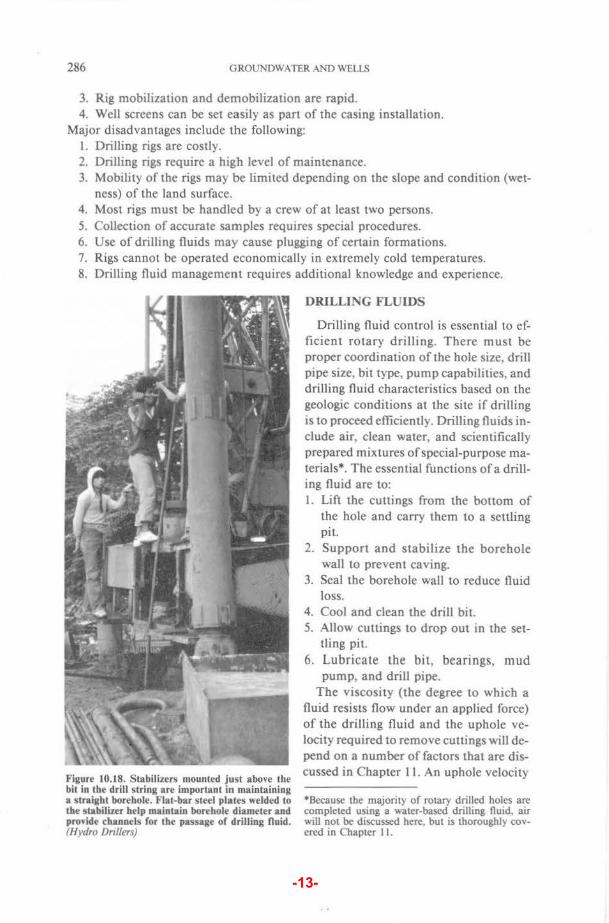
Figure 10.18. Stabilizers mounted just above the bit in the drill string are important in maintaining a straight borehole. Flat-bar steel plates welded to the stabilizer help maintain borehole diameter and provide channels for the passage or drilling fluid. (Hydro Drillers)
DRILLING FLUIDS
Drilling fluid control is essential to efficient rotary drilling. There must be proper coordination of the hole size, drill pipe size, bit type, pump capabilities, and drilling fluid characteristics based on the geologic conditions at the site if drilling is to proceed efficiently. Drilling fluids include air, clean water, and scientifically prepared mixtures of special-purpose materials*. The essential functions of a drilling fluid are to: I. Lift the cuttings from the bottom of
the hole and carry them to a settling pit.
2. Support and stabilize the borehole wall to prevent caving.
3. Seal the borehole wall to reduce fluid loss.
4. Cool and clean the drill bit. 5. Allow cuttings to drop out in the set
tling pit. 6. Lubricate the bit, bearings, mud
pump, and drill pipe. The viscosity (the degree to which a
fluid resists flow under an applied force) of the drilling fluid and the uphole velocity required to remove cuttings will depend on a number of factors that are discussed in Chapter II. An uphole velocity
*Because the majority of rotary drilled holes are completed using a water-based drilling Ouid, air will not be discussed here, but is thoroughly covered in Chapter II.
-13-
WELL DR It LING METHODS 287
of 100 to 150ft/min (30.5 to 45.7 mfmin) is used by many drillers (Table I 0.2). The ability of the fluid to lift cuttings in-creases rapidly as viscosit> and velocit> are increased. After cuttings arc brought to the surface. however. it is essential that they drop out as the fluid flows through the settling pit. The desired results arc obtained by selecting the appropriate drilling fluid additive, properly designing the mud ptts. controlling the viscosity and weight of the drilling fluid, and adjusting the pump speed.
When ctrculation of the dnlling fluid is interrupted for some reason, to add drill pipe for example, the cuttings being carned by the mud column tend to drop back tOward the bottom of the hole. Cuttings can bridge on tool joints and build up on top of the bit if they settle rapidly. Excessive pump pressures rna} then be required to move these cuttings and resume circulation; if the cuttings cannot be removed. the drill pipe and bit become
stuck in the hole (sanded in). Many drill-ing fluids develop gel strength. that is, the ability to suspend cuttings when flow slows or stops. It rna> be advisable before adding drill pipe to circulate the fluid
Pon
Box
Tapered elevatoon shOulder (seat)
"'ake·alld·break shoulder
Box countertx>re
Tong orea
Hard faced area
'
Figure 10.19. Drill pipe is hea,)-~alled ~eamless tubing with tool-joint pin and bo'-end fittings.
for a few minutes without applying bit pressure to clear the hole of most cuttings. This is particularly important for deep holes.
The drilling fluid prevents caving of the borehole because it exerts pressure against the wall. As long as the hydrostatic pressure of the fluid exceeds the earth pressures
Figure 10.20. A rotar)' table rotates the keiJ), ~hich is connedcd to the top of the drill string. The kcll) can be square, hexaj:lonal, or round with flutes cut into the outer watt. (lluron DrillmtV
and any confining pressure in the aquifer, the hole will remain open. The pressure at any depth is equal to the weight of the drilling fluid column above that point.
The weight of the drilling fluid required for a given situation cannot be predicted precisely without test borings. Most water well drillers rely on past experience in making up drilling fluid. If caving occurs while drilling, weighting material may be added to increase the drilling fluid weight or special additives may be added to isolate any swelling clays. To prevent excessive intrusion of fine drilling fluid par-
-14-
288 GROUNDWATER AND WELLS
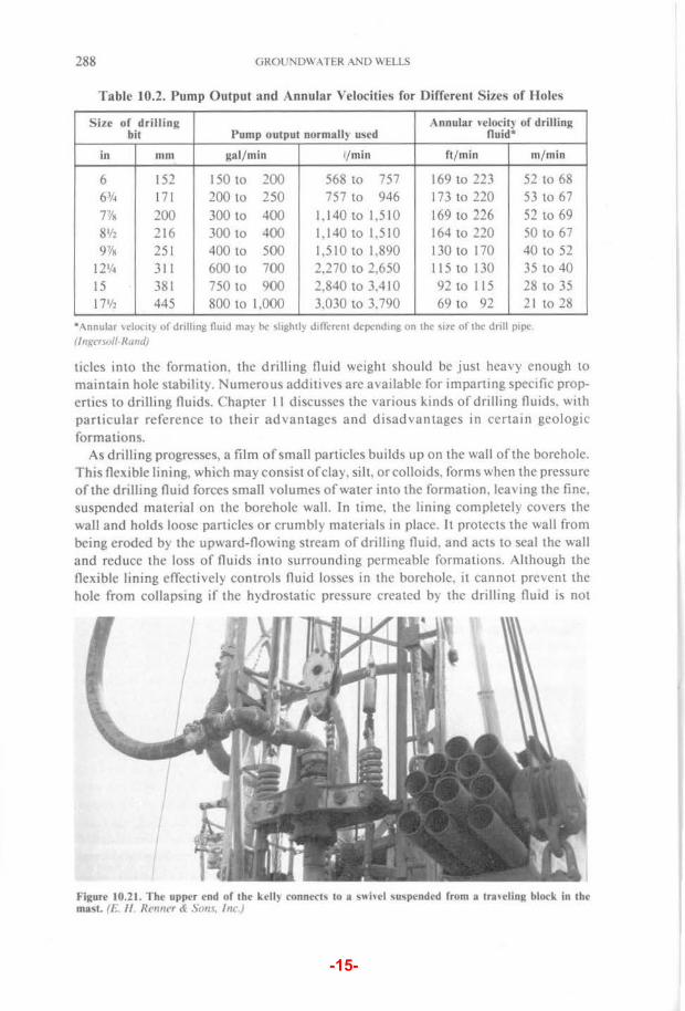
Table 10.2. Pump Output and Annular Velocities for Different Sizes of lloles
Size of drilling bit Pump output normally used
Annular \Ciocity of drilling fluid*
in mm gal/min ~/min ft / min m/min
6 152 150 to 100 568 to 757 169 to 223 52 to 68 63f4 171 200 to 250 757 to 946 173 to 220 53 to 67
7'/R 200 300 to 400 1,140 to 1,510 169 to 226 52 to 69 8112 216 300 to 400 1,140 to 1.510 164 to 220 50 to 67 97/R 251 400 to 500 1,510 to 1,890 130 to 170 40 to 52
121/4 311 600 to 700 2,270 to 2.650 115 to 130 35 to 40 IS 381 750 to 900 2,840 to 3.410 92 to 115 28 to 35 17112 445 800 to 1,000 3,030 to 3,790 69 to 92 21 to 28
•Annular 'clocll) ol dnlhng flutd rna) oc ~light!~ dtflcr~:nt dcpcndmg on the ~llC of the drill p1pc (Ingersoll-Rand)
tides into the formation, the drilling fluid weight should be just heavy enough to maintain hole stability. Numerous additives are available for imparting specific properties to drilling fluids. Chapter II discusses the various kinds of drilling flUids. with particular reference to their advantages and disadvantages in certain geologic formations.
As drilling progresses, a film of small particles builds up on the wall of the borehole. This flexible lining, which may consist of clay. sill, or colloids, forms when the pressure of the drilling fluid forces small volumes of water into the formation. lea"ing the fine. suspended material on the borehole wall. In time, the lining completely covers the wall and holds loose particles or crumbly materials in place. It protects the wall from being eroded by the upward-flowmg stream of drilling fluid. and acts to seal the wall and reduce the loss of fluids into surrounding permeable formations. Although the flexible lining effectively controls fluid losses in the borehole. it cannot prevent the hole from collapsing if the hydrostatic pressure created by the dnlling fluid is not
Figure 10.21. The upper end of the kelt) connect~ to a S\\ hel \uspended from a tra,eling block in the mast. (t. II Renner & Sons. Inc)
-15-
WELL DRILLING METHODS 289
greater than the pressure exerted by the water in the formation.
The drill bit is cooled and cleaned by the jets of fluid that are directed at relatively high velocity over the cutting faces and body section of the bit. A properly prepared drilling fluid is an excellent lubricant, but the viscosity must be controlled so that the concentration of cuttings does not become excessive.
In direct rotary drilling, water and special viscosity-building additives are usually mixed to produce a drilling fluid. Drilling fluids can be mixed in either a portable pit carried from site to site (Figure 10.24) or in a pit excavated next to the drilling rig. Cuttings collecting on the bottom of the pit must be removed periodically to maintain the efficiency of the pit (Figure 10.25). When enough drilling fluid has been mixed and sufficient time has elapsed to insure complete hydration, it is circulated into the hole using a mud pump. The size of the mud pump must be chosen carefully so that the correct uphole velocity can be maintained. Centrifugal and piston mud pumps are discussed in Chapter 17.
In clay-rich formations, the driller may begin drilling with clean water which quickly mixes with the natural clays in the borehole to form a thin clay slurry.
Figure 10.22. On some direct rotary rigs, a tophead drive is used to rotate the drill string. The amount or torque delivered to the bit by a top-head drive is usually somewhat less than that produced by a table drive, but the rod-handling speed is exceptionally good. (Olson Brothers Well Drilling)
This drilling fluid is used in the upper portion of the borehole, commonly the first I 00 to 300ft (30.5 to 91.5 m). Thereafter, most drillers will mix fluids with additives of either high-quality clays or natural or synthetic polymers so that proper viscosity and hydrostatic pressure can be maintained in the borehole.
REVERSE CIRCULATION ROTARY DRILLING
In direct rotary drilling, the viscosity and uphole velocity of the drilling fluid are the controlling factors in removing cuttings effectively. Unless cuttings can be removed, drilling cannot continue. Because of limitations in pump capacity and therefore effective cuttings removal, most direct rotary machines used to drill water wells are limited to boreholes with a maximum diameter of 22 to 24 in (559 to 610 mm). This size may not be sufficient for high-capacity wells, especially those that are to be filter packed. Also, as hole diameters increase past 24 in, the rate of penetration by direct rotary machines becomes less satisfactory. To overcome the limitation on hole diameter and drilling rate, reverse circulation machines were designed; originally they
-16-
Table 10.9. Relatil·e Performance of Different Drilling Methods in Various Types of Geologic Formations 1..> 1..> 00
Dinrt ROW) Dinct Rotary Direct Direct (Oown-th~
~ ReTet"'H Re-,e-rse
Cablr Ro~ Ro~ bole air ROW) Roearr Hydraulk T) pe of fo;rmslion Tool (..;oh floHis) (.nth au) haaa~M-r) ("ith n wds) (Daal Wall) PtTCUS:'Iion Jetting, 0rif"f'D AIIIU
"Assuming sufficient hydrostatic pressure is available to contain active sand (under high con lining pressures)
Rate of Penetration: I Impossible 2 Difficult 3 Slow 4 Medium 5 Rapid 6 Very rapad
-17-
WELL DRILLING METHODS 339
the position of the axis or center line of the well bore. Figure I 0. 70 is a graph for a well that is both out of plumb and crooked. The graph indicates that the casing is straight and plumb to a depth of 40 ft (12.2 m). The deflection at the 40-ft level is caused by a dogleg in the casing. From this point to a depth of about 90 ft (27.4 m), the casing is straight but out of plumb. Below 90ft, the rate of drift gradually increases and the casing is neither straight nor plumb.
CONCLUSIONS
Selection of the best drilling method for a particular job requires an understanding of the geologic conditions and the physical limitations of the drilling rig. In addition, the value of experience cannot be overestimated, for many drilling difficulties occur because either the driller is unprepared to handle the wide range of subsurface conditions or has pushed the rig beyond safe operating limits. Good record keeping, patience, and a willingness to learn are some important characteristics of good drillers; the age of the machine or the particular drilling method used are of secondary importance in drilling successful wells. Table 10.9 gives the drilling performance of different drilling methods in various geologic formations. The relative performance differences between drilling methods, however, will also depend on the experience of the driller, the presence of geologic anomalies at the site, and the pressure conditions affecting the groundwater.
-18-
360 GROUNDWATER AND WELLS
ionic; that is, they are not held together by electrical charges. Therefore, a polymeric addit ive does not produce a thixotropic condition in a drilling fluid. When calculating the yield point of a drilling fluid, it is important to realize that the calculated yield point for bentonite (a true thixotropic drilling fluid) is a direct indication of its gel strength. No similar comparison can be made for a drilling fluid made with polymeric additives; the calculated yield point is a meaningless figure because the drilling fluid does not have any gel strength.
Natural polymers such as Revert• can
Figure 11.18. Hydrostatic pressure in the borehole forces the drilling fluid into the formation as drilling proceeds. Cia) particles in the drilling fluid form a filter (mud) cake on the borehole \\all during this fluid loss. As the filter cake becomes thicker, the fluid loss is reduced significantly. The thickness of the filter cake is measured in multiples of 32nds of an inch.
be strongly gelled chemically when a sudden plugging effect is needed in a borehole (for example, in zones of lost circulation). When borate is added to Revert" and the pH of the water is above 7.5, the borate ion acts as a crosslinking agent with hydrated guar gum to form cohesive three-dimensional gels (Figure 11.1 7). The gel strength is determined by pH, temperature, and the concentration of reactants (boron and guar colloids). If temperature and concentration are held constant, the gel strength will increase if the pH of the water is raised from 7.5 to 9.2, the optimum pH (Henkel Corporation, Minneapolis, MN). At optimum conditions, the drilling fluid is similar to a firm, food-grade gelatin. The Revert• gel can be liquified by dropping the pH slightly below 7.0, which changes the hydrated borate ion [B(OH)4] to boric acid [B(OH)J]. Lowering the pH significantly below 7.0 may destroy the viscous characteristics of the drilling fluid. Filtra tion
Another of the principal requirements for a drilling fluid is to prevent fluid loss by forming a filter cake or low-permeability film on the porous face of the borehole. The sealing property depends on the amount and nature of the colloidal materials in the drilling fluid. T he filter cake produced by clays and the thin film created by polymeric colloids are physically dissimilar, because the size and shape of the particles differ and their ability to hydrate is significantly different. Colloidal particles and suspended cuttings entrained during drilling are important components of the total solids that create a filter cake or film. Thus, the filtration properties of all drilling fluids are, in part, supplied by materials derived from the borehole.
When drilling begins, hydrostatic pressure in the borehole causes the drilling fluid to flow into porous formations . For drilling fluids made with clay additives, the fluid and some clay particles initally enter the formation unhindered; but as the suspended solids and cuttings continue to close off the pores, clay particles filter out and form a cake on the borehole wall. As the remaining pores around the borehole become clogged with particles, progressively smaller volumes of water can pass into the formation (Figure 11.18). In time, a filter cake effectively limits water flow through the borehole wall except in highly permeable zones where lost circulation is apt to occur.
Permeability of the filter cake depends on the type of clay used in the drilling fluid; generally, the higher the number of colloidal particles, the lower the permeability.
-19-
502 GROUNDWATER AND WELLS
Filter Pack Thickness
The thickness of the filter pack has considerable effect on development efficiency. This happens for two reasons. First, the filter pack reduces the amount of energy reaching the borehole wall. The thinner the filter pack, the easier it is to remove all the undesirable fine sand, silt, and clay when developing the well. Second, a filter pack is so permeable that water may flow vertically in the filter pack envelope at places where the formation may be partially clogged, rather than move into or out of the natural formation. To permit the transfer of development energy to the borehole wall, filter packs normally should be no more than 8 in (203 mm) thick and should be properly sized and graded according to the design criteria given in Chapter 13.
Type of Formation
Different types of formations are developed more effectively by using certain development methods. For example, highly stratified, coarse-grained deposits are most effectively developed by methods that concentrate energy on small parts of the formation. In uniform deposits, development methods that apply powerful surging forces over the entire well bore produce highly satisfactory results. Other development methods that withdraw or inject large volumes of water quickly can actually reduce the natural hydraulic conductivity of formations containing a significant amount of silt and clay.
WELL DEVELOPMENT METHODS
Different well development procedures have evolved in different regions because of the physical characteristics of aquifers and the type of drilling rig used to drill the well. Unfortunately, some development techniques are still used in situations where other, more recently developed procedures would produce better results. New development techniques, especially those using compressed air, should be considered by contractors when they buy and equip a new rig. Any development procedure should be able to clean the well so that sand concentration in the water is below the maximum allowable limit set for the particular water use.
Overpumping
The simplest method of removing fines from water-bearing formations is by overpumping, that is, pumping at a higher rate than the well will be pumped when put into service. This procedure has some merit, because any well that can be pum~d sand free at a high rate can be pumped sand free at a lower rate.
Overpumping, by itself, seldom produces an efficient well or full stabilization of the aquifer, particularly in unconsolidated sediments, because most of the development action takes place in the most permeable zones closest to the top of the screen. For a given pumping rate, the longer the screen, the less development will take place in the lower part of the screen. After fine material has been removed from the permeable zones near the top of the screen, water entering the screen moves preferentially through these developed zones, leaving the rest of the well poorly developed and contributing only small volumes of water to the total yield. In some cases, overpumping may compact finer sediments around the borehole and thereby restrict flow into the screen. If more powerful agitation is not performed, an inefficient well rna}
-20-
DEVELOPMENT OF WATER WELLS 503
result. On the other hand, overpumping may be effective in filter-packed wells in competent, relatively non-stratified sandstone formations because flow toward the well bore is more or less uniform.
There is another objection to overpumping that is commonly overlooked. Water flows in only one direction, toward the screen, and some sand grains may be left in a bridged condition, resulting in a formation that is only partially stabilized (Figure 15.4). If this condition exists and the formation is agitated during normal pump cycles after the well has been completed, sediment may enter the well if the sand bridges become unstable and collapse.
Drillers ordinarily use a test pump for overpumping operations, but when a large quantity of water must be pumped, it may be difficult to obtain equipment of sufficient capacity at reasonable cost.
Bridge
Well screen
Figure 15.4. During development by O\'erpumping, sand grains can bridge openings because flow occurs in onl) one direction. Once the ,.ell is placed into service, agitation b) normal pump cycling can break down the bridges, causing sand pumping.
Therefore, the pumping equipment intended for regular well use is sometimes used for overpumping. Depending on the type of pump, this may be done either by operating the pump at a higher speed or by allowing the pump to discharge at the surface at a lower-than-normal operating pressure. There is one serious objection to performing this work with the permanent pump. Sand pumping will subject the pump to excessive wear, which over time can reduce its operating efficiency. Under severe conditions, the pump may become sand locked, either during pumping or after shut ofT. Should sand locking occur, the pump must be pulled, disassembled, cleaned, and repaired if necessary before being placed back into service.
Backwashing
EfTective development procedures should cause reversals of flow through the screen openings that will agitate the sediment, remove the finer fraction, and then rearrange the remaining formation particles (Figure 15. 5). Reversing the direction of flow breaks down the bridging between large particles and across screen openings that results \\hen the water flows in only one direction. The backflow portion of a backwashing qcle breaks down bridging, and the inflow then moves the fine material toward the screen and into the well.
A surgmg action consists of alternately lifting a column of water a significant distance above the pumping water level and letting the water fall back into the well. rhis process is called rawhiding. Before beginning the surging operation, the pump should be started at reduced capacity and gradually increased to full capacity to minimi.~:e the danger of sand-locking the pump. In the rawhiding procedure, the pump ts started, and as soon as water is lifted to the surface the pump is shut off; the water tn the pump column pipe then falls back into the well. The pump is started and
-21-
504 GROUNDWATER AND WELLS
Figure 15.5. Effective development action requires movement of water in both directions through screen openings. Reversing flow helps break do"n bridging of particles. Movement in only one direction, as "hen pumping from the "ell, does not produce the proper development effect.
stopped as rapidly as the power unit and starting equipment will permit. To avoid damagjng the pump, the control box should be equipped with a starter lockout so that the pump cannot be started when it is back spinning. During the procedure, the well should be pumped to waste occasionally to remove the sand that has been brought in by the surging action.
Some wells respond satisfactorily to rawhiding, but in many cases the surging effect is not vigorous enough to obtain maximum results. As in the case of overpumping, the surging effects may be concentrated only near the top of the screen or in the most permeable zones. Thus, the lower part of a long screen may remain relatively undeveloped.
Although overpumping and backwashing techniques are used widely, and in certain situations may produce reasonable results, their overall effectiveness in high-capacity wells is relatively limited when compared with other development methods. Other methods, as described below, are capable of removing more fine materials in less time and generally can produce higher specific capacities.
Mechanical Surging
Another method of development is to force water to flow into and out of a screen by operating a plunger up and down in the casing, similar to a piston in a cylinder. The tool normally used is called a surge block, surge plunger, or swab (Figure I 5.6). A heavy bailer may be used to produce the surging action, but it is not as effective as the close-fitting surge block. Although some drillers depend on surge blocks for developing screened wells, others feel that this device is not effective and that it rna), in some cases, even be detrimental because it forces fine material back into the formation before the fines can be removed from the well. To minimize this problem, fine material should be removed from the borehole as often as possible.
Before starting to surge, the well should be bailed to make sure that water will flow into it. Lower the surge block into the well until it is I 0 to I 5 ft (3 to 4.6 m) beneath
-22-
DEVELOPMENT OF W.\TER WELLS
the static water level, but above the
505
Pl~ll screen or packer (Figure 15. 7). The water column will effectively transmit the action of the block to the screen section. The initial surging motion should be relatively gentle, allowing any material blocking the screen to break up, go into suspension, and then move into the well. The surge block (or bailer) should be operated with particular care if the formation above the screen consists mainly of fine sand, silt, or soft clay which may
i l i;f1J~~~~:·~ i:~J~f;~~~D::~~~ ·;::::;~{;~~~~~:~~?;}..<~. .•... ;. ;biQC~ -- ....... ,, .. , ..•..
. Nli';}j~:t,.:·.· .,"(~ltlif~(~it1tru Figure 15.7. For certain types of formations, a 'urge block is an effective tool for well development. On the do~nstroke, ~ater is forced outward into the formation; water, silt. and fine sand are thtn pulled into the well screen during the up,tro~e.
Figure 15.6. Typical surge block consisting of two leather or rubber discs sandwiched between three steel or wooden discs. The blocks are constructed so that the outside diameter of the rubber lips is equal to the inside diameter of the screen. The solid part of the block is 1 in (25.4 mm) smaller in diameter than the screen.
slump into the screen. As water begins to move easily both into and out of the screen, the surging tool is usually lowered in steps to just above the screen. As the block is lowered, the force of the surging movement is increased. In a well equipped with a long screen, it may prove more effective to operate the surge block in the screen to concentrate its action at various levels. Development should begin above the screen and move progressively downward to prevent the tool from becoming sand locked.
The force exerted on the formation depends on the length of the stroke and the vertical velocity of the surge block. For a cable tool rig, length of the stroke is determined by the spudding motion; the vertical velocity depends on the weight exerted on the block and the retraction
-23-
506 GROUNDWATER AND WELLS
speed. A block must be weighted so that it will fall at the desired rate when used with a cable tool rig. During retraction of the block, continue the spudding motion to avoid sand locking the block in the casing. If a rotary rig is being used, the weight on the block is provided by the drill pipe. The speed of retraction and length of pull are governed by the physical characteristics of the rig.
Continue surging for several minutes, then pull the block from the well. Air may be used to blow the sediment out of the well if development is done with a rotary rig or if an air compressor is available. Sediment can be removed by a bailer or sand pump when a cable tool rig is used. The surging action is concentrated at the top of the screen, and this effect is accentuated if the lower part of the screen is continually blocked off by the sand brought in by the development process. In general, development can be accelerated if the amount of sediment in the screen is kept to a minimum. A sump or length of casing installed beneath the screen is helpful in keeping the screen free of sediment. Continue surging and cleaning until little or no sand can be pulled into the well. Total development time may range from about 2 hours for small wells to many days for large wells with long screens.
Occasionally, surging may cause upward movement of water outside the well casing if the washing action disrupts the seal around the casing formed by the overlying sediments. When this occurs, use of the surge block must be discontinued or sediment from the overlying materials may invade the screened zone.
Surge blocks sometimes produce unsatisfactory results in certain formations, especially when the aquifer contains many clay streaks, because the action of the block can cause clay to plug the formation. When this happens a reduction in yield occurs, rather than an increase. Surge blocks are also less useful when the particles making up the formation are angular, because angular particles do not sort themselves as readily as rounded grains. In addition, if large amounts of mica are present in the aquifer, the flat or tab-alar mica flakes can clog the outer surface of the screen and the zone around the screen by aligning themselves perpendicular to the direction of flow. Clogging by mica can be minimized if the surging procedures are applied rather gently to the well. It is good practice to avoid overdevelopment when mica is present in the aquifer.
One other type of surging tool is called a swab. The simplest type of swab, a rub-
cable':'· . ... . · . . · ..
·, . ·. :~alve. · .". '. ··
Figure 15.8. Line swabbing is used primarily in consolidated aquifers. As the swab is pulfed upward at about 3 ft/sec (0.9 mjsec), high-pressure conditions at the top of the swab force water into the formation. Low-pressure conditions at the base cause flow of sand, silt, and water back into the borehole.
-24-
DEVELOPMENT OF WATER WELLS 507
ber-flanged mud scow or bailer, is lowered into the casing to any selected point below the water level and then pulled upward at about 3 ft/sec (0.9 mjsec), with no attempt to reverse the flow and cause a surging effect (Figure 15.8). The length of the swabbing stroke is usually much longer than in surging. As the scow is raised, high pressure is created near the top of the scow, which drives water into the formation. Water is drawn back into the well beneath the swab because the pressure is lower. The scow usually has a valve at the bottom which opens to increase the fall rate in the borehole. This method of swabbing, called line swabbing, is often used to clean fine material from deep wells drilled in consolidated rock aquifers. Swabbing screened wells requires special precautions, however. In
Figure 15.9. When a double-flanged Sl>ab is used, water is pumped into the formation bet"een the flanges. Flo" reenters the borehole above or below the swab. During pumping, the Sl>ab is raised and lowered O\er short distances.
tight (low-permeability) formations, for example, swabbing can result in collapsed screens, and great care must be taken to insure that the hydraulic conductivity of the formation is capable of yielding sufficient water to keep pressure differentials within reasonable limits. A void swabbing wells that have plastic casing or screens. Silt and silty sand formations in which screen-slot sizes are about 0.0 I 0 in (0.25 mm) or smaller are particularly troublesome, and use of a swab in this case should be avoided.
A more effective swabbing device is shown in Figure 15.9. With this tool, water is pumped into the formation between two flanges and returns to the well bore either above or below the flanges. During pumping, the swab is raised and lowered in the borehole over short distances. Sometimes a bypass tube is installed in the doubleflanged swab to facilitate the movement of water up the borehole from below the tool. The advantage of a double-flanged swab is that the energy of the water being pumped into the tool can be directed at selected parts of the formation.
In summary, surge blocks are inexpensive tools that are convenient to use and, within their limitations, do an effective job. They can be adapted for use on many types of rigs and used in combination with other development methods. In addition, surge blocks can be used for wells of any diameter or depth. Surging procedures produce good results for screen installations in zones having good porosity and hydraulic conductivity.
Air Developing by Surging and Pumping
Many drillers use compressed air to develop wells in consolidated and unconsolidated formations. The practice of alternately surging and pumping with air has grown \\ith the great increase in the number of rotary drilling rigs equipped with large air compressors. In air surging, air is injected into the well to lift the water to the surface. ,\s tt reaches the top of the casing, the air supply is shut off, allowing the aerated water column to fall. Air-lift pumping is used to pump the well periodically to remove
-25-
DEVELOPMENT OF WATER WELlS 521
from the well should be settled out in a tank or settling pit before this water is recirculated. To enhance the development process, chemicals such as polyphosphates are often added to the jetting water to help break up clays.
When air-lift pumping is impractical, a submersible pump can be used during jetting. Usually the pump must be placed well above the jetting tool so that the amount of sand passing through the pump is minimized. Thus, the pump causes material temporarily placed in suspension by the jetting action to move into the screen, but much of the material falls to the bottom. This sediment must be removed periodically during the jetting and pumping operation so the entire screen is developed.
A COMPARISON OF THREE DEVELOPMENT METHODS
Certain development methods exert more powerful cleaning forces on the formation than do others, and thus are better able to remove the drilling fluid and create a zone of high porosity and hydraulic conductivity around the screen. Results from an experimental well field at the Irrigation Research Center at Staples, Minnesota demonstrate the relative differences in three development methods. Ten irrigation wells were constructed at Staples in surficial glacial outwash, using three types of well screens. This site was chosen because of the highly uniform nature of the aquifer. All wells were drilled by the direct rotary drilling method. Two different drilling fluid additives were used - bentonite and polymer. After well construction, each screen was developed in three stages; first by overpumping, second by mechanical surging, and third by water jetting and simultaneous air-lift pumping. Each development method was continued until the water was essentially sand free. A 24-hour pumping test was conducted after each of the three development episodes; data were acquired, analyzed, and stored with the aid of a computer system. The Staples investigation is one of the few scientific studies conducted in a uniform aquifer that examines many of the well construction and completion variables that affect development.
Results of the study show that the average specific capacities of the wells drilled with bentonite improved 74 percent when overpumping was followed successively by mechanical surging and simultaneous water jetting/air-lift pumping (Figure 15.20). Drawdown data suggest overpumping is the least effective of these three development methods, whereas simultaneous water jetting/airlift pumping removed sediment and drilling fluid that the other development methods could not dislodge. In general, test data from Staples show that the eventual specific capacity of a well depends to a great extent on what development method is used.
As suggested earlier in this chapter, the Improvement in specific capacity
~
E" a. 20 Ol
u :;:: '(3 10 2t en Q)
~ Q)
> ~
0 After over
pumping
After surging
13.6
After jetting
Figure 15.20. Average specific capacities of wells drilled with bentonite, after various development methods. Individual specific capacities were measured when no more sediment could be dislodged from the formation by a particular development method. (Werner eta/., 1980)
-26-
522 GROUNDWATER AND WELLS
achieved by any development method may be seriously retarded because of limited open area. For the wells drilled with bentonite, those completed with screens having more than 15 percent open area had 52 percent greater specific capacities than those completed with screens having less than 15 percent open area (Figure 15.21}. As the open area of the screen is increased, the enhanced effectiveness of the development causes a corresponding increase in specific capacity.
The specific capacity of a well is also a function of which drilling fluid is selected. For each development episode, wells drilled with polymer averaged 56 percent higher specific capacities than did the wells drilled with bentonite (Figure 11.21 , page 362) (Werner et al., 1980). This difference occurs because some of the bentonite penetrates farther into the formation during the drilling process than any development method can reach. On the other hand, polymeric drilling fluids beyond the reach of a development method simply break down naturally over time and thus offer no resistance to flow.
USE OF POLYP HOSPHATES IN DEVELOPMENT
Adding a small amount of a polyphosphate before or during development helps considerably in removing clays that occur naturally in the aquifer and those clays introduced into the borehole as part of the drilling fluid. Polyphosphates disperse the clay particles in the formation so they can be removed. Enough time must be allowed between introduction of the polyphosphate and development, usually overnight, so the clay masses become completely disaggregated (see Chapter II}. After the polyphosphate solution is jetted or surged into the screen, water should be added to the well to drive the solution farther into the formation.
Two types of polyphosphates a~e used in well development- crystalline and glassy. Crystalline polyphosphates that help remove clays from the aquifer are sodium acid pyrophosphate (SAPP), tetrasodium pyrophosphate (TSPP), and sodium tripoly
phosphate (STP). Sodium hexametaphos
~ e a. 20 Ol
10
Screens with less than 15%
open area
10.410.8
7.8
phate (SHMP) is a glassy phosphate that Screens Wlth I is readily available and therefore often
more than 15% I used in developing wells. About 15 lb (6.8 open area
16.4
13.5 :·:
~ 7.8 ~;
1 kg) of a polyphosphate should be used for I each 100 gal (0.4 m ') of water in the
screen. Two pounds (0.9 kg) of sodium I hypochlorite (3 to 15 percent chlorine so-
llution) also should be added to every I 00 gal of water in the well to control bacterial growth promoted by the presence of
v'
o~~~~~~--~~~~~~:~, ~~ 1st 2nd 3rd 1st 2nd 3rd
polyphosphates. Polyphosphates should be premixed
before introduction into the well because
Development stage
Figure I 5.2 1. Open area of the well scr een controls the effectiveness of \·arious development methods for wells drilled "ith bentonite. In general, development is most effecthe "hen the screen open area is the largesl. (Werner et a! .. 1980: Dnscoll et a! .. 1980a)
they do not mix easily with cold water. Occasionally the mix water is heated to help dissolve the chemical. In general, the lighter the density, the more quickly the polyphosphate will go into solution. So-dium tripolyphosphate, for example, is
-27-
DEVELOPMENT OF WATER WELLS 523
available in three densities. If the polyphosphate is jetted, some contractors use a solution with twice the recommended concentration. A larger amount of polyphosphate, however, does not give significantly better results when used for drilling fluid dispersion and, under certain conditions, may cause serious problems.
Care must be exercised if SHMP is used because the phosphate can become glassy in the well under certain conditions, causing severe plugging of the formation and screen. For example, an over-rich solution ofSHMP can precipitate glassy phosphates on contact with the cold groundwater found typically in northern Europe and southern Canada. These glassy precipitates are gelatinous masses that are extremely difficult to remove because no effective solvents exist. Acids will break down the glassy condition eventually, but the time required is impractical for efficient well development. Therefore, glassy phosphates should never be dumped undissolved into a well. The use of a glassy phosphate also can be undesirable in certain formations. Although little is known about the exact chemical conditions that may cause the phosphate to become semisolid in a borehole, experience has shown that the use of SHMP can be a problem in glauconitic sandstones. SHMP is available in plate form, crushed, or as a powder, which affects the density of the product.
The addition of wetting agents to polyphosphates will increase their effectiveness in disaggregating clays. One pound (0.5 kg) of wetting agent (for example, Pluronic F-68) is added to 100 gal (0.4 m3) of polyphosphate solution. Wetting agents and polyphosphates should not be used in formations with thinly bedded clays and sands, because these chemicals tend to make the clays near the borehole unstable, causing them to mix with the sand. The hydraulic conductivity of the aquifer near the borehole is then reduced and clay continually passes into the borehole during each pumping cycle.
DEVELOPMENT OF ROCK WELLS
All drilling methods cause some plugging of fractures and crevices in hard-rock formations. In softer formations such as sandstone, the borehole wall may become clogged with finer material. In cable tool drilling, the bit action chips and crushes the rock and mixes it with water and other fine material to form a slurry. The pounding of the bit forces some of this slurry into the openings in the rock outside the borehole. When drilling fluids are used in rock drilling, they also may plug crevices. Even airdrilling methods can blow large quantities of fine material into openings in the rock, causing drastic reductions iin yield.
Any material that clogs openings in the rock aquifer must be removed by a development procedure. The full yield of the formation can be realized only if all the fractures and crevices can provide water to the well. Pumping alone sometimes pulls out the remaining sediment because the openings in rock formations are relatively large in comparison with the pores in a sand formation. However, many drillers have found that surging or other means of development for rock wells is needed to obtain maximum capacity.
One of the best methods used to clean rock holes is the water jetting/air-lift pumping method in which inflatable packers are used to isolate the zones that supply water to the well. As in the case of screened wells, the jetting action dislodges loose material from the borehole wall and from the cracks and crevices in the formation. It has been shown that much of the water entering an open borehole enters through these fracture
-28-
524 GROUNDWATER AND WELLS
zones. If they are partially plugged with drill cuttings, the water can become turbulent and thus cause higher head losses and significantly reduced specific capacity as yields are increased.
Development of Sandstone Wells
Blasting and bailing techniques have long been used in an attempt to reduce sand pumping and enhance yields from wells constructed in weakly consolidated sandstones. Usually, blasting and bailing techniques are used after other development methods have been applied. To reduce sand pumping, some drillers blast a sandstone aquifer to create a much larger cavern. In theory, the average flow velocity toward the well from the borehole face will be so low that the transport of sand will not occur. Unfortunately, sand pumping does not stop in many cases because the aquifer materials continue to slough off and fill the enlarged borehole. The inability to reduce sand pumping to acceptable levels shows that these procedures may not be cost effective. Recently, an increasing number of friable sandstone wells have been screened rather than blasted to assure control of sand pumping, even though some loss of specific capacity may occur. Screening a well in sandstone may be impractical in some circumstances, because the loss in yield may be unacceptable.
Blasting and bailing are also used to increase the yield by enlarging the effective well diameter. Walton ( 1962) has shown, for example, that yields increased an average of 29 percent after blasting and bailing techniques had been applied. In many cases, however, the blasting and bailing procedure may take months to perform and add significantly to overall costs. Thus, blasting a sandstone aquifer may not increase the yield enough to justify the additional costs and may not eliminate a sand-pumping problem.
A powerful technique has been developed to clean sandstone wells that combines air-lift pumping, air pressurizing, and rawhiding. This combination of methods overcomes development difficulties caused by the geologic makeup of many sandstone aquifers. These aquifers are often highly stratified, with certain layers cemented by silica, calcium, or iron, or by fine material such as clay. Cementation resulted when minerals were deposited by groundwater flowing along highly permeable lenses of the sandstone after it was uplifted.
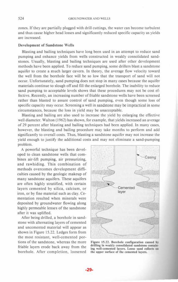
After being drilled, a borehole in sandstone with alternating layers of cemented and uncemented material will appear as shown in Figure 15.22. Ledges form from the most resistant, well-cemented portions of the sandstone, whereas the more friable layers erode back away from the borehole. After completion, loosened
Cemented layer
··casing ·
Figure 15.22. Borehole configuration caused by drilling in weakly consolidated sandstone containing well-cemented layers. Loose sand collects on the upper surface of the cemented layers.
-29-
DEVELOPMENT OF WATER WELLS 525
Compressor
6-in ·· ·.· ·. ~equctor .··. . pipe ·:
· ·Air line··
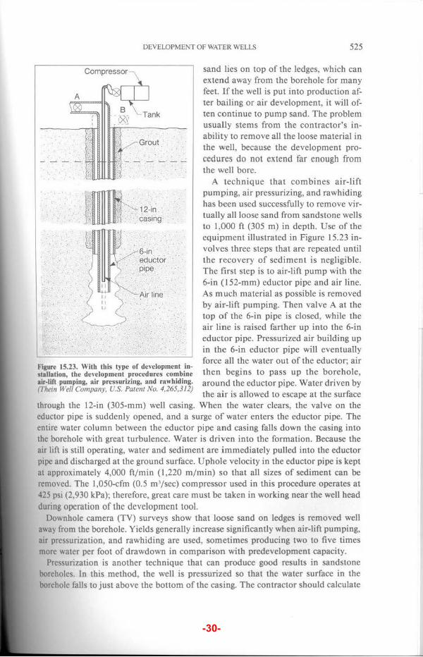
Figure 15.23. With this type of development instaiJation, the development procedures combine air-lift pumping, air pressurizing, and rawhiding. (Thein Well Company, U.S. Patent No. 4,265,312)
sand lies on top of the ledges, which can extend away from the borehole for many feet. If the well is put into production after bailing or air development, it will often continue to pump sand. The problem usually stems from the contractor's inability to remove all the loose material in the well, because the development procedures do not extend far enough from the well bore.
A technique that combines air-lift pumping, air pressurizing, and rawhiding has been used successfully to remove virtually all loose sand from sandstone wells to 1,000 ft (305 m) in depth. Use of the equipment illustrated in Figure 15.23 involves three steps that are repeated until the recovery of sediment is negligible . The first step is to air-lift pump with the 6-in (152-mm) eductor pipe and air line. As much material as possible is removed by air-lift pumping. Then valve A at the top of the 6-in pipe is closed, while the air line is raised farther up into the 6-in eductor pipe. Pressurized air building up in the 6-in eductor pipe will eventually force all the water out of the eductor; air then begins to pass up the borehole, around the eductor pipe. Water driven by the air is allowed to escape at the surface
through the 12-in (305-mm) well casing. When the water clears, the valve on the eductor pipe is suddenly opened, and a surge of water enters the eductor pipe. The entire water column between the eductor pipe and casing falls down the casing into the borehole with great turbulence. Water is driven into the formation. Because the air lift is still operating, water and sediment are immediately pulled into the eductor pipe and discharged at the ground surface. Uphole velocity in the eductor pipe is kept at approximately 4,000 ft/min {1,220 m/min) so that all sizes of sediment can be removed. The 1,050-cfm (0.5 m 3/ sec) compressor used in this procedure operates at 425 psi (2,930 kPa); therefore, great care must be taken in working near the well head during operation of the development tool.
Downhole camera (TV) surveys show that loose sand on ledges is removed well away from the borehole. Yields generally increase significantly when air-lift pumping, air pressurization, and rawhiding are used, sometimes producing two to five times more water per foot of drawdown in comparison with predevelopment capacity.
Pressurization is another technique that can produce good results in sandstone boreholes. In this method, the well is pressurized so that the water surface in the borehole falls to just above the bottom of the casing. The contractor should calculate
-30-
526 GROUNDWATER AND WELlS
the amount of pressure required so that extra pressure does not force the water below the bottom of the casing, thereby blowing air into the formation. A quickopening valve mounted on a plate fastened to the top of the casing is then suddenly opened, causing a rush of water into the well. Sand and silt particles move into the borehole and then settle to the bottom. Compression-decompression cycles are repeated until the sediment fills a significant part of the well and must be removed. It can be either bailed or removed by air-lift pumping. The eductor pipe and air line are placed in the well and then the casing cap is attached (Figure 15.24). Pressurization can also be accomplished in the method illustrated in Figure 15.23 by closing valves A and B.
Figure 15.24. In the pressurization method, the eductor and air line are placed in the well and then the casing is capped. (Bergerson·Caswe/1, Inc.)
ALLOWABLE SEDIMENT CONCENTRATION IN WELL WATER
Sediment in water supplies can be destructive to pumps and to water-discharge fittings such as the nozzles on irrigation systems. Although development methods
Figure 15.25. The concentration of suspended sediment can be estimated by collecting water and sediment in a large container. (Olson Bros. Well Drilling Company, Inc.)
reduce or eliminate high concentrations of sediment in well water, it is impractical to assume that all sediment transport can be eliminated, even by the most powerful development methods. Therefore, some judgment must be used to establish allowable concentrations. The term "sandfree water" as used in this text describes water that contains less than S, mg/! of sand, silt, or clay.
The concentration of suspended sediment in water is usually estimated by using a large container (Figure 15.2 5), a centrifugal sand sampler (Figure 15.26), or an Imhoff cone (Figure 15.27). Containers such as the Imhoff cone are less accurate in estimating sediment concentrations because of their small volumes. The sediment concentration is determined by averaging the results of five samples taken at the following times during the final pumping test: (1) 15 minutes after start of test, (2) after 25 percent of the total pumping test time has elapsed, (3)