12
OIC ™ AL PEEK Spacer System Surgical Technique

OIC™ AL PEEK Spacer SystemSurgical Technique
Anterior Lumbar InterbodyFusion Technique
Introduction
The OIC™ AL (Anterior Large) PEEK Spacer is intend-ed for use as an interbody fusion device. This implanthas serrations on the superior and inferior surfaces forfixation. It is offered in two footprints (22mm x28mm and 28mm x 33mm), two lordotic angles (4°and 8°), and a variety of heights ranging from 10mmto 20mm in (2mm increments).
The following surgical technique describes a one-levelanterior lumbar interbody fusion (ALIF) procedureusing the OIC™ AL PEEK Spacer with a left sidedanterior approach.
The OIC™ AL PEEK Spacer is indicated for the treat-ment of degenerative spine disorders, discal and verte-bral instability as well as spondylolisthesis and cases ofspine revision surgery. It is recommended to pack bonegraft material inside.
The OIC™ AL PEEK Spacer is intended for use withsupplemental fixation. The supplemental fixation sys-tems that may be used with the Stryker® Spine OIC™AL PEEK Spacer include, but are not limited to,Stryker® Spine plate rod or rod systems (XIA®, Trio®and Radius).This comprehensive system overview highlights thefundamental design, material, positioning, sizing, andfusion features of the OIC™ AL PEEK Spacer System.
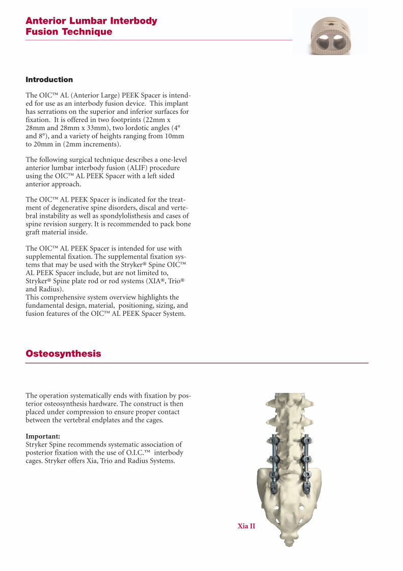
The operation systematically ends with fixation by pos-terior osteosynthesis hardware. The construct is thenplaced under compression to ensure proper contactbetween the vertebral endplates and the cages.
Important:Stryker Spine recommends systematic association ofposterior fixation with the use of O.I.C.™ interbodycages. Stryker offers Xia, Trio and Radius Systems.
Osteosynthesis
Xia II

Step 1: Surgical ApproachThe patient is placed on the operating table in a lateraldecubitus position and a left anterolateral approach isperformed. A retroperitoneal or combined thoraco-lumbar approach is recommended (Fig. 1).
Confirm the appropriate level radiographically.
ALIFApproach
Fig. 1 - Retroperitoneal Approach
Step 2: Disc RemovalAn anterior annulotomy is performed and should bewide enough to allow insertion of the implant (Fig. 2).The OIC™ AL PEEK Spacer is offered in 28mm and33mm mediolateral widths. It is recommended that theappropriate width be selected based on pre-operativemeasurements.
Using Rongeurs, Pituitaries, Curettes and/or Kerrisons,a discectomy is subsequently performed until anappropriate amount of the disc material has beenremoved, the posterior longitudinal ligament isexposed, and decompression is achieved.
Distraction is performed using a conventional verte-bral body distractor in the usual manner. Curettes areused to elevate additional disc material from the end-plates, taking care not to damage the lateral annulus.
Fig. 2 - An anterior annulotomy is performedto allow for implant insertion.

ALIFSite Preparation
Step 3: Endplate PreparationStraight and angled curettes should be translated par-allel to the endplates until sufficient decortication isachieved (Fig. 3). The curettes can be used to "feel"the endplates ensuring that no soft tissue remains.
Fig. 3 - A curette may be used to sufficientlydecorticate the endplates.
Step 4: Trial SizingIt is recommended that preliminary measurements aretaken to determine the appropriate Trial size.
A Trial is placed in the intra-discal space to determinethe appropriate implant size (Fig. 4). Properly sizedTrials should fit flush within the confines of the ante-rior cortex and posterior cortex producing a tightinterface with both the superior and inferior endplates.Care should be taken not to use a Trial that is too largefor the disc space, for this may result in overdistrac-tion. Since the overall shape of the OIC™ AL Trialsmimic the footprint profiles of the implants them-selves, select the OIC™ AL PEEK Spacer based on theTrial size.
Fig. 4 - Inserting the trial into the intra-discal space.
Step 5: Implant PreparationThe OIC™ AL Spacer has 3 different insertion holes toprovide 3 different insertion angle options. Based onthe size of the implant and angle of approach, choosethe appropriate implant and orientation.
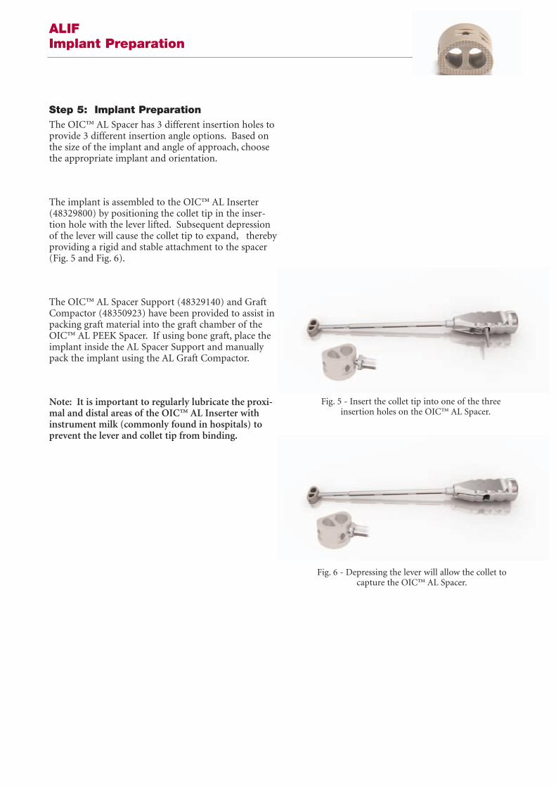
The implant is assembled to the OIC™ AL Inserter(48329800) by positioning the collet tip in the inser-tion hole with the lever lifted. Subsequent depressionof the lever will cause the collet tip to expand, therebyproviding a rigid and stable attachment to the spacer(Fig. 5 and Fig. 6).
The OIC™ AL Spacer Support (48329140) and GraftCompactor (48350923) have been provided to assist inpacking graft material into the graft chamber of theOIC™ AL PEEK Spacer. If using bone graft, place theimplant inside the AL Spacer Support and manuallypack the implant using the AL Graft Compactor.
Note: It is important to regularly lubricate the proxi-mal and distal areas of the OIC™ AL Inserter withinstrument milk (commonly found in hospitals) toprevent the lever and collet tip from binding.
ALIF Implant Preparation
Fig. 5 - Insert the collet tip into one of the three insertion holes on the OIC™ AL Spacer.
Fig. 6 - Depressing the lever will allow the collet tocapture the OIC™ AL Spacer.
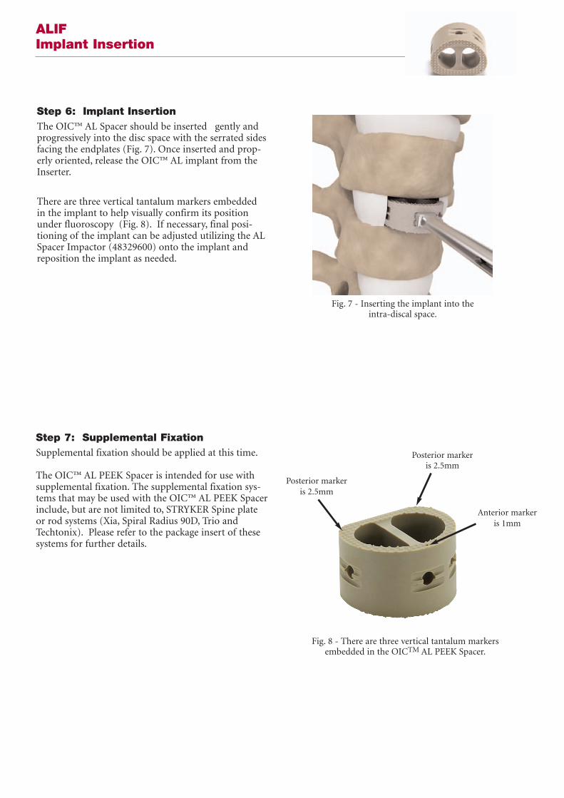
Step 6: Implant InsertionThe OIC™ AL Spacer should be inserted gently andprogressively into the disc space with the serrated sidesfacing the endplates (Fig. 7). Once inserted and prop-erly oriented, release the OIC™ AL implant from theInserter.
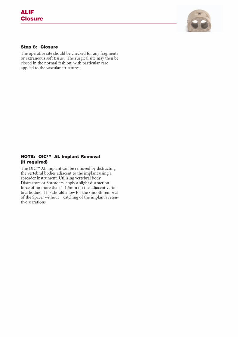
There are three vertical tantalum markers embeddedin the implant to help visually confirm its positionunder fluoroscopy (Fig. 8). If necessary, final posi-tioning of the implant can be adjusted utilizing the ALSpacer Impactor (48329600) onto the implant andreposition the implant as needed.
ALIF Implant Insertion
Fig. 8 - There are three vertical tantalum markersembedded in the OICTM AL PEEK Spacer.
Step 7: Supplemental FixationSupplemental fixation should be applied at this time.
The OIC™ AL PEEK Spacer is intended for use withsupplemental fixation. The supplemental fixation sys-tems that may be used with the OIC™ AL PEEK Spacerinclude, but are not limited to, STRYKER Spine plateor rod systems (Xia, Spiral Radius 90D, Trio andTechtonix). Please refer to the package insert of thesesystems for further details.
Posterior markeris 2.5mm
Posterior markeris 2.5mm
Anterior markeris 1mm
Fig. 7 - Inserting the implant into the intra-discal space.
Step 8: Closure The operative site should be checked for any fragmentsor extraneous soft tissue. The surgical site may then beclosed in the normal fashion; with particular careapplied to the vascular structures.
NOTE: OIC™ AL Implant Removal(if required)The OIC™ AL implant can be removed by distractingthe vertebral bodies adjacent to the implant using aspreader instrument. Utilizing vertebral bodyDistractors or Spreaders, apply a slight distractionforce of no more than 1-1.5mm on the adjacent verte-bral bodies. This should allow for the smooth removalof the Spacer without catching of the implant’s reten-tive serrations.
ALIF Closure

OIC™ AL PEEK Spacer SystemSet Configuration
*For size availability, please contact your local sales representative.
48326104 Vertebral Spacer 10 x 22 x 28 x 4˚ 1
48326124 Vertebral Spacer 12 x 22 x 28 x 4˚ 2
48326144 Vertebral Spacer 14 x 22 x 28 x 4˚ 3
48326164 Vertebral Spacer 16 x 22 x 28 x 4˚ 3
48326184 Vertebral Spacer 18 x 22 x 28 x 4˚ 2
48326204 Vertebral Spacer 20 x 22 x 28 x 4˚ 1
48328104 Vertebral Spacer 10 x 28 x 33 x 4˚ 1
48328124 Vertebral Spacer 12 x 28 x 33 x 4˚ 2
48328144 Vertebral Spacer 14 x 28 x 33 x 4˚ 3
48328164 Vertebral Spacer 16 x 28 x 33 x 4˚ 3
48328184 Vertebral Spacer 18 x 28 x 33 x 4˚ 2
48328204 Vertebral Spacer 20 x 28 x 33 x 4˚ 1
OIC AL Implants – 4˚Reference # Description Qty in Set
48326108 Vertebral Spacer 10 x 22 x 28 x 8˚ 1
48326128 Vertebral Spacer 12 x 22 x 28 x 8˚ 2
48326148 Vertebral Spacer 14 x 22 x 28 x 8˚ 3
48326168 Vertebral Spacer 16 x 22 x 28 x 8˚ 3
48326188 Vertebral Spacer 18 x 22 x 28 x 8˚ 2
48326208 Vertebral Spacer 20 x 22 x 28 x 8˚ 1
48328108 Vertebral Spacer 10 x 28 x 33 x 8˚ 1
48328128 Vertebral Spacer 12 x 28 x 33 x 8˚ 2
48328148 Vertebral Spacer 14 x 28 x 33 x 8˚ 3
48328168 Vertebral Spacer 16 x 28 x 33 x 8˚ 3
48328188 Vertebral Spacer 18 x 28 x 33 x 8˚ 2
48328208 Vertebral Spacer 20 x 28 x 33 x 8˚ 1
OIC AL Implants – 8˚Reference # Description Qty in Set

OIC™ AL PEEK SpacerInstrument Set Configuration
48329500 AL Inserter 2
48329600 AL Impactor 1
48329140 Graft Support 1
48329160 Graft Compactor 1
48329800 Trial Handle 1
48329710 AL Trial 22 x 10 1
48329712 AL Trial 22 x 12 1
48328714 AL Trial 22 x 14 1
48328716 AL Trial 22 x 16 1
48328718 AL Trial 22 x 18 1
48328720 AL Trial 22 x 20 1
48328910 AL Trial 28 x 10 1
48328912 AL Trial 28 x 12 1
48328914 AL Trial 28 x 14 1
48328916 AL Trial 28 x 26 1
48328918 AL Trial 28 x 18 1
48328920 AL Trial 28 x 20 1
48328920 AL Trial 28 x 20 1
48322228 Total AL PEEK Container 1
OIC™ AL InstrumentsReference # Description Qty in Set

Indications andContraindications
IndicationsThe OIC™ AL PEEK Spacer is indicated for the treat-ment of degenerative spine disorders, discal and verte-bral instability as well as in cases of spine revision sur-gery. It is recommended to pack bone graft materialinside the implant.
The OIC™ AL PEEK Spacer is intended for use withsupplemental fixation. The supplemental fixation sys-tems that may be used with the OIC™ AL PEEK Spacerinclude, but are not limited to, STRYKER Spine plateor rod systems (Xia, Spiral Radius 90D, Trio andTechtonix).
Contraindicationso The OIC™ AL PEEK Spacer should not be implant-ed in patients with an active infection at the operativesite.
o Marked local inflammation.
o The OIC™ AL PEEK Spacer is not intended for useexcept as indicated.
o Any mental or neuromuscular disorder which wouldcreate an unacceptable risk of fixation failure or com-plications in postoperative care.
o Bone stock compromised by disease, infection orprior implantation, which cannot provide adequatesupport and/or fixation to the devices.
o Open wounds.
o Pregnancy.
o Inadequate tissue coverage over the operative site.
o Rapid joint disease, bone absorption, osteopenia,osteomalacia, and/or osteoporosis. Osteoporosis orosteopenia are relative contraindications, since thiscondition may limit the degree of obtainable correc-tion and/or the amount of mechanical fixation.
o Anytime implant utilization would interfere withanatomical structures or physiological performanceand/or the amount of mechanical fixation.
Other medical or surgical conditions that could pre-clude the potential benefit of surgery, such as congeni-tal abnormalities, immunosuppressive disease, eleva-tion of sedimentation rate unexplained by other dis-eases, elevation of white blood count (WBC), ormarked left shift in the WBC differential count, mustbe carefully analyzed before surgery.
These contra-indications can be relative or absoluteand must be taken into account by the physician whenmaking his decision. The above list is not exhaustive.
CautionBased on the fatigue testing results, thephysician/surgeon should consider the levels ofimplantation, patient weight, patient activity level,other patient conditions, etc. which may impact on theperformance of the system.
Surgeons should warn patients of all relevant risks, aswell as the limitations and risks of the device.
Operative Precautions
Pre-Operative Precautions:The surgical indication and the choice of implantsmust take into account certain important criteria suchas:
o Patients involved in an occupation or activitythat applies excessive loading upon the implant (e.g.,substantial walking, running, lifting, or muscle strain)may be at increased risk for failure of the fusion and/orthe device.o Patients should be instructed in detail aboutthe limitations of the implants, including, but notlimited to, the impact of excessive loading throughpatient weight or activity, and be taught to govern theiractivities accordingly. The procedure will not restorefunction to the level expected with a normal, healthyspine, and the patient should not have unrealistic func-tional expectations.o A condition of senility, mental illness, chemicaldependence or alcoholism. These conditions amongothers may cause the patients to ignore certain neces-sary limitations and precautions in the use of theimplant, leading to failure and other complications.o Foreign body sensitivity. Where material sensi-tivity is suspected appropriate tests should be madeprior to material implantation.o Patients who smoke have been shown to havean increased incidence of non-unions. Such patientsshould be advised of this fact and warned of the poten-tial consequences.o Care must be taken to protect the components
from being marred, nicked, or notched as a result ofcontact with metal or abrasive objects.o Surgeons must discuss these precautions pre-operatively with their patients.o The choice of proper shape, size and design ofthe implant for each patient is crucial to the success ofthe surgery. The surgeon is responsible for this choicewhich depends on each patient.o The size and shape of the bone structuresdetermine the size, shape and type of the implants.Once implanted, the implants are subjected to stressesand strains. These repeated stresses on the implantsshould be taken into consideration by the surgeon atthe time of the choice of the implant, during implanta-tion as well as in the post-operative follow-up period.Indeed, the stresses and strains on the implants maycause fatigue, fracture or deformation of the implants,before the bone graft has become completely consoli-dated. This may result in further side effects or necessi-tate the early removal of the device.
Intra-Operative PrecautionsThe insertion of the implants must be carried outusinginstruments designed and provided for this purposeand in accordance with the specific implantationinstructions for each implant.o Discard all damaged or mishandled implants.o Never reuse an implant, even though it mayappear undamaged.
Post-Operative Precautionso Physician instructions regarding full weight-bearing activities must be complied with until matura-tion of the fusion mass is confirmed. Failure to complywith physician instructions may result in failure of theimplant, the fusion, or both.

This document is intended solely for the use of healthcare professionals.
The information presented in this brochure is intended to demonstrate the breadth of Stryker product offerings.Always refer to the package insert, product label and/or user instructions before using any Stryker product. Productsmay not be available in all markets. Product availability is subject to the regulatory or medical practices that governindividual markets. Please contact your Stryker representative if you have questions about the availability of Strykerproducts in your area.
Products referenced with ™ designation are trademarks of Stryker.Products referenced with ® designation are registered trademarks of Stryker.
Literature Number: MTXIBASLST06091MTX/GS 03/07
Copyright © 2006 Stryker
Stryker SACité-CentreGrand-Rue 901820 MontreuxSwitzerland
t : +41 21 966 12 01
f : +41 21 966 12 00
www.europe.stryker.com


