16
Oil Circulating Heating System Hazardous Location 216268-000 REV 2 Installation & Operation Manual
Oil Circulating Heating System
Hazardous Location
216268-000 REV 2
Installation & Operation Manual
i
Identifying Your System
The HOTSTART heating system is designed to heat fluids for use in marine propulsion, diesel-powered
generator sets, locomotives, gas compression, or any large-engine applications. The system is pre-wired,
pre-plumbed, and assembled on a steel plate. Each heating system has an identification plate which
includes the part number and serial number.
Warranty information can be found at www.hotstart.com or by contacting our customer service
department at (509)536-8660. Have your model and serial numbers ready when contacting the
warranty department.
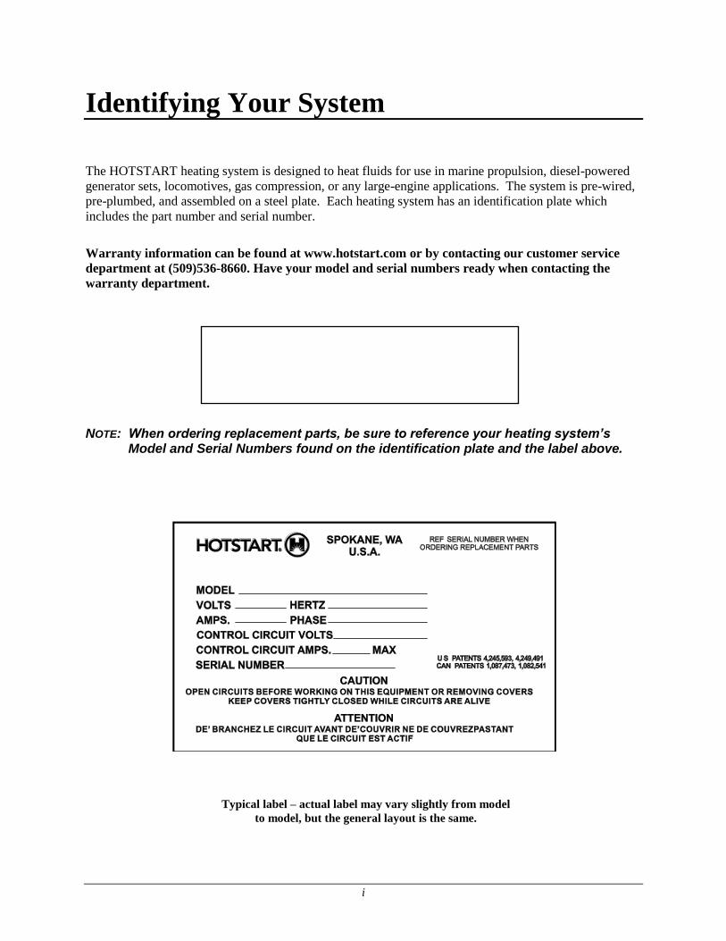
NOTE: When ordering replacement parts, be sure to reference your heating system’s Model and Serial Numbers found on the identification plate and the label above.
Typical label – actual label may vary slightly from model
to model, but the general layout is the same.
ii
NOTICE
Important Safety Information
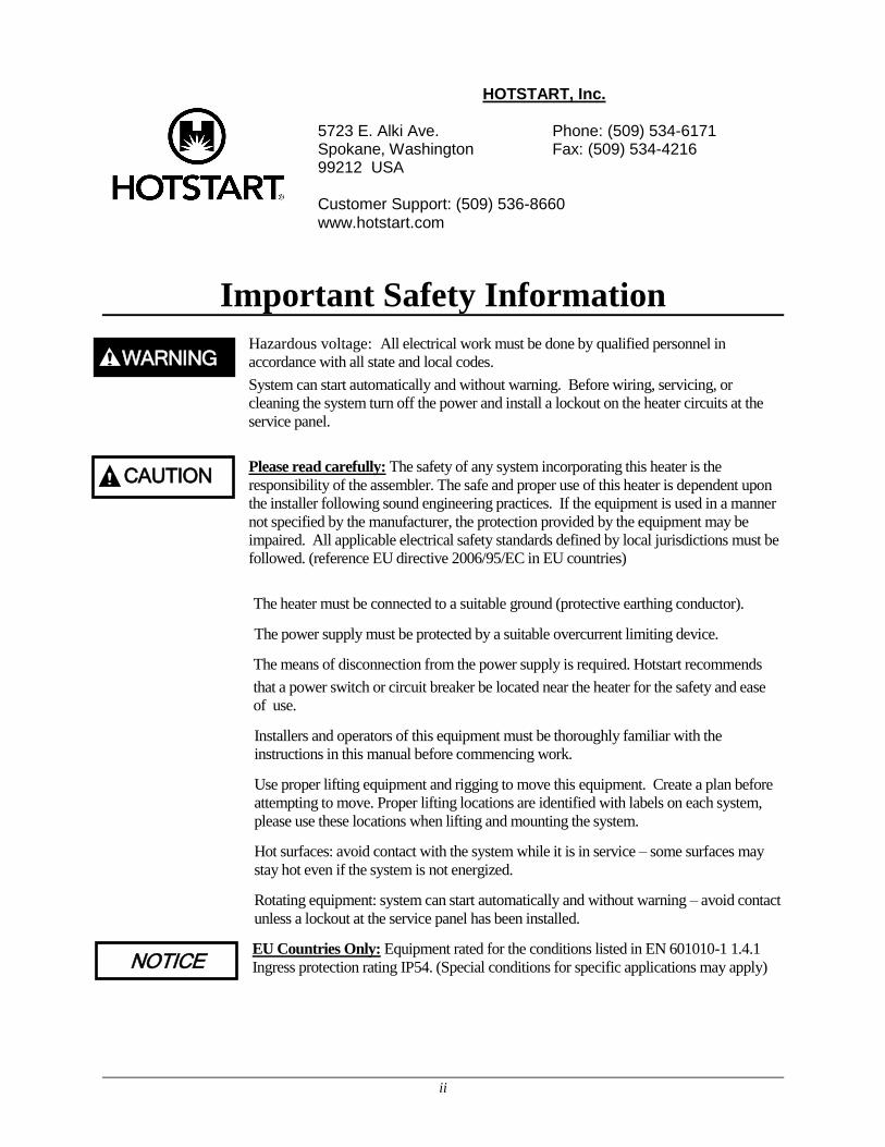
Hazardous voltage: All electrical work must be done by qualified personnel in
accordance with all state and local codes.
System can start automatically and without warning. Before wiring, servicing, or
cleaning the system turn off the power and install a lockout on the heater circuits at the
service panel.
Please read carefully: The safety of any system incorporating this heater is the
responsibility of the assembler. The safe and proper use of this heater is dependent upon
the installer following sound engineering practices. If the equipment is used in a manner
not specified by the manufacturer, the protection provided by the equipment may be
impaired. All applicable electrical safety standards defined by local jurisdictions must be
followed. (reference EU directive 2006/95/EC in EU countries)
The heater must be connected to a suitable ground (protective earthing conductor).
The power supply must be protected by a suitable overcurrent limiting device.
The means of disconnection from the power supply is required. Hotstart recommends
that a power switch or circuit breaker be located near the heater for the safety and ease
of use.
Installers and operators of this equipment must be thoroughly familiar with the
instructions in this manual before commencing work.
Use proper lifting equipment and rigging to move this equipment. Create a plan before
attempting to move. Proper lifting locations are identified with labels on each system,
please use these locations when lifting and mounting the system.
Hot surfaces: avoid contact with the system while it is in service – some surfaces may
stay hot even if the system is not energized.
Rotating equipment: system can start automatically and without warning – avoid contact
unless a lockout at the service panel has been installed.
EU Countries Only: Equipment rated for the conditions listed in EN 601010-1 1.4.1
Ingress protection rating IP54. (Special conditions for specific applications may apply)
HOTSTART, Inc. 5723 E. Alki Ave. Phone: (509) 534-6171 Spokane, Washington Fax: (509) 534-4216 99212 USA Customer Support: (509) 536-8660 www.hotstart.com
CAUTION
WARNING

iii
Table of Contents 1 Installation ............................................................................................................................................ 1
1.1 Oil Plumbing Diagram .................................................................................................................. 1
1.2 Mounting ....................................................................................................................................... 1
1.3 Oil Suction Line Requirements ..................................................................................................... 2
1.4 Lube Oil Discharge Line ............................................................................................................... 3
1.5 Main Power Supply ....................................................................................................................... 3
1.6 Customer Interface Connections ................................................................................................... 4
2 Heating System Start-Up ...................................................................................................................... 5
3 Overview of Operation ......................................................................................................................... 6
4 System Components and Operation ..................................................................................................... 7
4.1 Prime Button ................................................................................................................................. 7
4.2 Local/Off/Remote 3-Position Switch ............................................................................................ 7
4.3 Remote Control Relay ................................................................................................................... 7
4.4 Control TCR (Temperature Control Relay) .................................................................................. 7
4.5 High Limit TCR ............................................................................................................................ 7
4.6 Motor Protective Switch (MPS) .................................................................................................... 7
5 Maintenance, Repair, and Troubleshooting ......................................................................................... 8
5.1 System Maintenance ..................................................................................................................... 8
5.1.1 Plumbing Connections .......................................................................................................... 8
5.1.2 Electrical Connections .......................................................................................................... 8
5.1.3 System Mounting .................................................................................................................. 8
5.1.4 Magnetic Contactors ............................................................................................................. 8
5.1.5 Pump Seal ............................................................................................................................. 8
5.1.6 Volatile Corrosion Inhibitor (VCI) ....................................................................................... 8
5.1.7 Heating Element Replacement .............................................................................................. 9
5.1.8 Reassembly of Heating Element and Tank ......................................................................... 10
5.1.9 RTD Replacement ............................................................................................................... 11
5.2 Troubleshooting .......................................................................................................................... 12
1
1 Installation
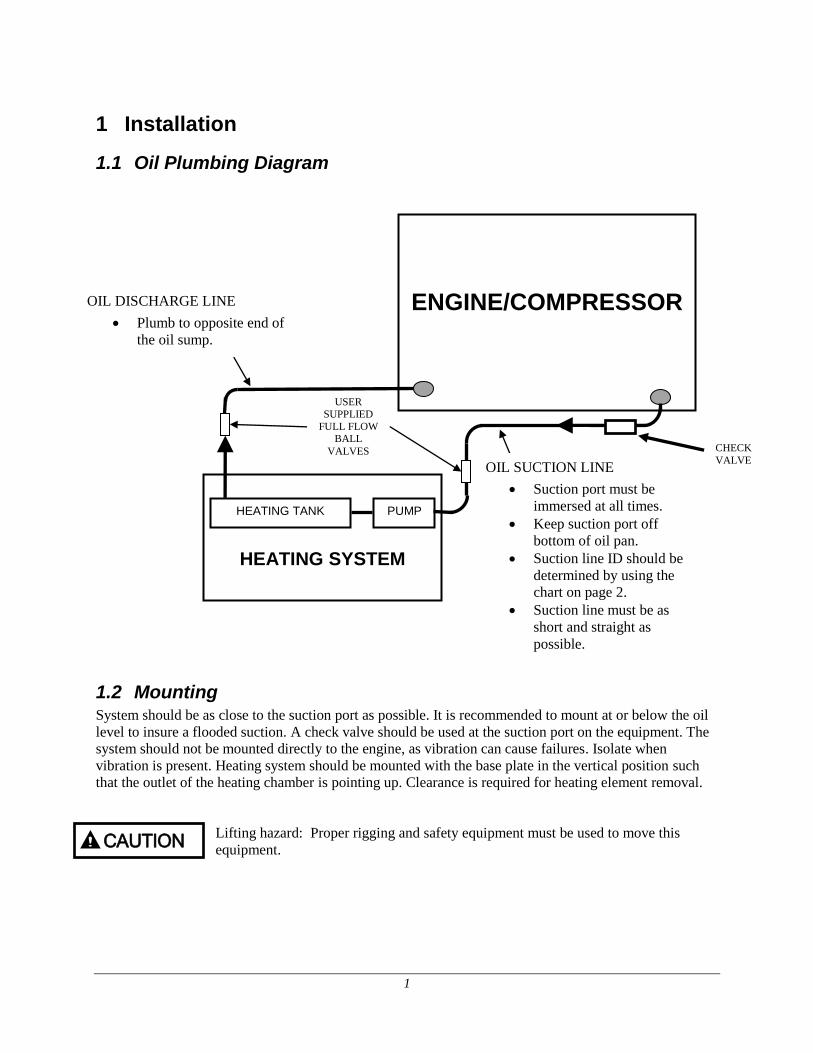
1.1 Oil Plumbing Diagram
1.2 Mounting System should be as close to the suction port as possible. It is recommended to mount at or below the oil
level to insure a flooded suction. A check valve should be used at the suction port on the equipment. The
system should not be mounted directly to the engine, as vibration can cause failures. Isolate when
vibration is present. Heating system should be mounted with the base plate in the vertical position such
that the outlet of the heating chamber is pointing up. Clearance is required for heating element removal.
Lifting hazard: Proper rigging and safety equipment must be used to move this
equipment.
CAUTION
CHECK
VALVE
ENGINE/COMPRESSOR
HEATING SYSTEM
PUMP HEATING TANK
USER
SUPPLIED
FULL FLOW BALL
VALVES
OIL DISCHARGE LINE
Plumb to opposite end of
the oil sump.
OIL SUCTION LINE
Suction port must be
immersed at all times.
Keep suction port off
bottom of oil pan.
Suction line ID should be
determined by using the
chart on page 2.
Suction line must be as
short and straight as
possible.
2
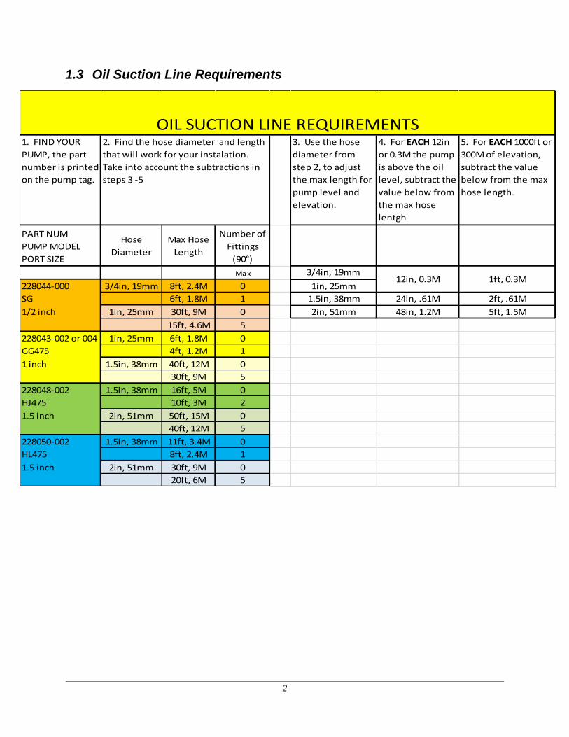
1.3 Oil Suction Line Requirements
1. FIND YOUR
PUMP, the part
number is printed
on the pump tag.
3. Use the hose
diameter from
step 2, to adjust
the max length for
pump level and
elevation.
4. For EACH 12in
or 0.3M the pump
is above the oil
level, subtract the
value below from
the max hose
lentgh
5. For EACH 1000ft or
300M of elevation,
subtract the value
below from the max
hose length.
PART NUM
PUMP MODEL
PORT SIZE
Hose
Diameter
Max Hose
Length
Number of
Fittings
(90°)
Max 3/4in, 19mm
228044-000 3/4in, 19mm 8ft, 2.4M 0 1in, 25mm
SG 6ft, 1.8M 1 1.5in, 38mm 24in, .61M 2ft, .61M
1/2 inch 1in, 25mm 30ft, 9M 0 2in, 51mm 48in, 1.2M 5ft, 1.5M
15ft, 4.6M 5
228043-002 or 004 1in, 25mm 6ft, 1.8M 0
GG475 4ft, 1.2M 1
1 inch 1.5in, 38mm 40ft, 12M 0
30ft, 9M 5
228048-002 1.5in, 38mm 16ft, 5M 0
HJ475 10ft, 3M 2
1.5 inch 2in, 51mm 50ft, 15M 0
40ft, 12M 5
228050-002 1.5in, 38mm 11ft, 3.4M 0
HL475 8ft, 2.4M 1
1.5 inch 2in, 51mm 30ft, 9M 0
20ft, 6M 5
OIL SUCTION LINE REQUIREMENTS2. Find the hose diameter and length
that will work for your instalation.
Take into account the subtractions in
steps 3 -5
12in, 0.3M 1ft, 0.3M

3
WARNING
1.4 Lube Oil Discharge Line
Size the discharge line per the outlet of the heating system. There are two options for the
discharge line of the Hotstart oil heating system. The heated oil can be returned to the opposite
end of the oil sump, or engine pre-lubing can be achieved by installing a tee in the discharge line
along with a solenoid valve or manual three-way valve.
Note: See engine manufacturer requirements for pre-lubing. Hotstart does not specify flow
rates or pressure for pre-lube systems.
Do not reduce the inlet line. Pump seal damage will occur.
Position the heating tank so that it is completely full of oil while in operation.
Fill the suction line with oil. Pump is not self-priming. Liquid must be present in the
Pump before start-up. Trapped air inside the pump will cause pump and seal damage.
After completing oil line installation, top-off the oil level to compensate for the oil
Used to fill the lines and heating tank. The system should be configured with user
Supplied full port ball valves in the oil lines, allowing maintenance on the heating
System without draining the engine oil.
1.5 Main Power Supply
Connect the specified power from the customer supplied circuit breaker to the terminal blocks located in
the main control box. For three phase applications, the terminal blocks are labeled L1, L2, and L3. For
single phase applications, use the terminal blocks labeled L1 and L3 or L and N. The circuit breaker must
be near the heating system and easily accessible.
The main power ground wire must be connected to the ground lug or ground block on the electrical panel
located inside the electrical box.
The main power supply operates the heating elements and the circulating pumps. A transformer is used to
operate the control circuit. The transformer and control circuits are overload protected with fuses and/or a
circuit breaker.
Hazardous Voltage: A lockout must be used at the service panel when
work is being done inside the control box to avoid electrocution.
All wiring shall be done by qualified personnel in accordance with national,
state, and local codes. Each system shall be grounded in accordance with
the National Electrical Code. Failure to properly ground the system may
result in electric shock.
NOTICE
4
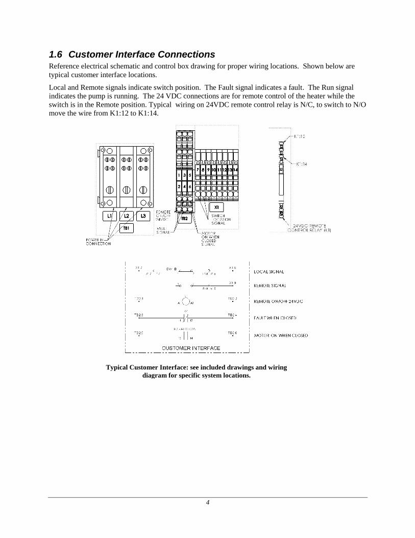
1.6 Customer Interface Connections Reference electrical schematic and control box drawing for proper wiring locations. Shown below are
typical customer interface locations.
Local and Remote signals indicate switch position. The Fault signal indicates a fault. The Run signal
indicates the pump is running. The 24 VDC connections are for remote control of the heater while the
switch is in the Remote position. Typical wiring on 24VDC remote control relay is N/C, to switch to N/O
move the wire from K1:12 to K1:14.
Typical Customer Interface: see included drawings and wiring
diagram for specific system locations.
5
NOTICE
WARNING
2 Heating System Start-Up
Step 1 Check and tighten all electrical and plumbing connections.
Step 2 Ensure isolation valves are open before energizing the system.
Step 3 Check for proper rotation of the motor by pressing the prime button while watching
the motor shaft or fan. Single phase systems are pre-wired to rotate in the correct
direction. On a three phase system, if the pump is not rotating in the correct direction,
switch any two electrical leads at the main power terminal block.
DO NOT RUN MOTOR/PUMP ASSEMBLY DRY FOR MORE THAN A FEW
SECONDS.
Running a pump that is not completely filled with liquid will cause damage to the
pump seal.
Step 4 Bleed all trapped air from the heating system by opening a plug or pipe fitting at or near
the pump. Press and hold the prime button to evacuate any remaining air in the lines.
When all the air is evacuated, the discharge pressure gauge should indicate pressure.
Step 5 Energize the heating system by switching the control switch to the Local position. A
pressure gauge should indicate pressure if the system is working correctly.
Hazardous Voltage: A lockout must be used at the service panel when work
is being done inside the control box to avoid electrocution.
Step 6 Once operation is satisfactory, turn the control dials on the Temperature Control Relay
TCR1 to the desired temperature setting. HOTSTART recommends a control
temperature (on TCR1) of 30 °C (86 °F). The high limit temperature setting (on TCR2)
should be set at 90 °C (194 °F).
The high limit TCR must be set at least 10 °C (18 °F) higher than the control TCR
for proper heating operation. This will avoid nuisance tripping of the high limit
circuit.
Step 7 Change the switch to the Remote position and verify that the 24 V DC controls operate
properly (refer to Section 4.3 for operation).
NOTICE
6
NOTICE
3 Overview of Operation When the system is energized, a positive displacement rotary gear pump takes oil from the engine sump
and forces it through the heating tank and into the return line. The return line can be routed back to the
sump, or can be sent to the top of the engine for pre-lube and post-lube purposes.
Note: See engine manufacturer requirements for pre-lubing. Hotstart does not specify flow rates or
pressure for pre-lube systems.
Continual pre-lubing can cause permanent engine damage. Consult the
engine manufacturer for proper pre-lube techniques.
The heating system is designed to run continuously while the engine is not running. The heating element
will cycle on and off with the system temperature controller to maintain the temperature.
7
4 System Components and Operation The control box contains the electrical control components for the heating system. The following is an
operational description for the standard parts located on the system, including:
Prime Button
3-Position Switch (Local/Off/Remote)
Remote Control Relay
Control TCR (Temperature Control Relay)
High Limit TCR
Motor Protective Switch (MPS)
4.1 Prime Button The prime button is used to assist with removal of remaining air in the suction and discharge lines
(without energizing the heating elements). This can be verified by an increase in pressure on the pressure
gauge.
4.2 Local/Off/Remote 3-Position Switch
Local – Manual control: the system turns on independent of the remote control relay.
Off – The system is shut off.
Remote – Automatic control: the system turns on and off via the remote control relay.
4.3 Remote Control Relay Typical wiring on 24VDC remote control relay is N/C. In this position the automatic control relay allows
the system to run and requires a 24 V DC signal to de-energize the system. To switch to N/O move the
wire from terminal 12 to terminal 14 on the remote control relay.
4.4 Control TCR (Temperature Control Relay) The control TCR is used to control the temperature of the engine oil. It uses a Resistance Temperature
Device (RTD) to sense the oil temperature of the fluid coming from the engine to the heater. The
standard setting for the control TCR is 30 °C (86 °F) and 10% hysteresis. The TCR will turn the heater
off at the set point of 30 °C (86 °F) and turn the heater on at 27 °C (81 °F) with these set points.
4.5 High Limit TCR The high limit TCR is a protective device to prevent overheating of the oil in the system, and the RTD is
located in the element enclosure. The default setting is 90 °C (194 °F) and should always be at least
10 °C (18 °F) higher than the control TCR set point. The high limit TCR hysteresis is not used in the
high limit control.
4.6 Motor Protective Switch (MPS) The MPS protects the motor from overloads. The MPS will be set at the full load amperage of the motor
when shipped from the factory. On hazardous location models, press the RESET button on the control
box lid to reset the motor protective switch (inside the control box).
8
WARNING
5 Maintenance, Repair, and Troubleshooting
5.1 System Maintenance Instructions for the following maintenance procedures are provided to ensure trouble-free operation of
your heating system. Replacement parts must meet or exceed original part requirements in order to
maintain the compliance level of the original heater.
• Plumbing Connections
• Electrical Connections and Contacts
• System Mounting
• Magnetic Contactors
• Pump Seal
• Volatile Corrosion Inhibitor
• Heating Tanks/Elements
After maintenance is performed, refer to the start-up section of this manual.
Hazardous voltage: Before wiring, servicing or cleaning the system, turn off the
power and install a lockout at the service panel. Failure to do so could allow others
to turn on power unexpectedly, which many cause fatal electrical shock.
5.1.1 Plumbing Connections
Periodically check plumbing connections for leaks and, if necessary, tighten connections. A
loose connection on the suction side will cause a loss of flow and cavitation in the pump. It can
also pull air into the heating tank and cause an element failure.
5.1.2 Electrical Connections
Vibration may eventually cause terminals to loosen. Tighten at start-up and check again in a
week. Tighten all electrical connections every 3 months.
5.1.3 System Mounting
Vibration may cause mounting bolts to loosen. Periodically check and tighten all mounting bolts.
5.1.4 Magnetic Contactors
Magnetic contactors are used as voltage switching controls for motors and heating elements in
HOTSTART Heating Systems. The contactors use 120 or 240 V coils. To test for failure, check
for continuity across the coil connections; an open or direct-short reading indicates a failed
contactor coil.
The contactor contacts should be inspected periodically for welding, arc erosion, and mechanical
wear. If any of these conditions exist, clean the contacts or replace the contactor.
5.1.5 Pump Seal
Leakage can occur at any time throughout the life of the seal. Always replace the seal at the first
sign of leakage. If the heating system is installed on an engine that is used for a critical
application, replace the seal annually. Instructions to replace the seal are included with the new
seal.
5.1.6 Volatile Corrosion Inhibitor (VCI)
A VCI is provided with each control box and should be replaced once a year.
9
WARNING
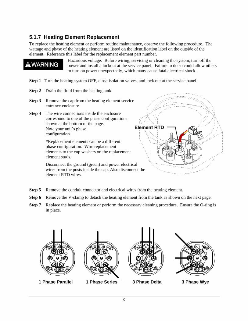
5.1.7 Heating Element Replacement
To replace the heating element or perform routine maintenance, observe the following procedure. The
wattage and phase of the heating element are listed on the identification label on the outside of the
element. Reference this label for the replacement element part number.
Hazardous voltage: Before wiring, servicing or cleaning the system, turn off the
power and install a lockout at the service panel. Failure to do so could allow others
to turn on power unexpectedly, which many cause fatal electrical shock.
Step 1 Turn the heating system OFF, close isolation valves, and lock out at the service panel.
Step 2 Drain the fluid from the heating tank.
Step 3 Remove the cap from the heating element service
entrance enclosure.
Step 4 The wire connections inside the enclosure
correspond to one of the phase configurations
shown at the bottom of the page.
Note your unit’s phase
configuration.
*Replacement elements can be a different
phase configuration. Wire replacement
elements to the cup washers on the replacement
element studs.
Disconnect the ground (green) and power electrical
wires from the posts inside the cap. Also disconnect the
element RTD wires.
Step 5 Remove the conduit connector and electrical wires from the heating element.
Step 6 Remove the V-clamp to detach the heating element from the tank as shown on the next page.
Step 7 Replace the heating element or perform the necessary cleaning procedure. Ensure the O-ring is
in place.
1 Phase Parallel 1 Phase Series 3 Phase Delta 3 Phase Wye
10
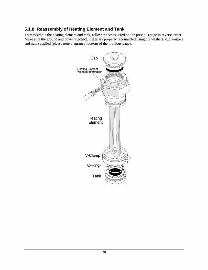
5.1.8 Reassembly of Heating Element and Tank
To reassemble the heating element and tank, follow the steps listed on the previous page in reverse order.
Make sure the ground and power electrical wires are properly reconnected using the washers, cup washers
and nuts supplied (please note diagram at bottom of the previous page).
11
WARNING
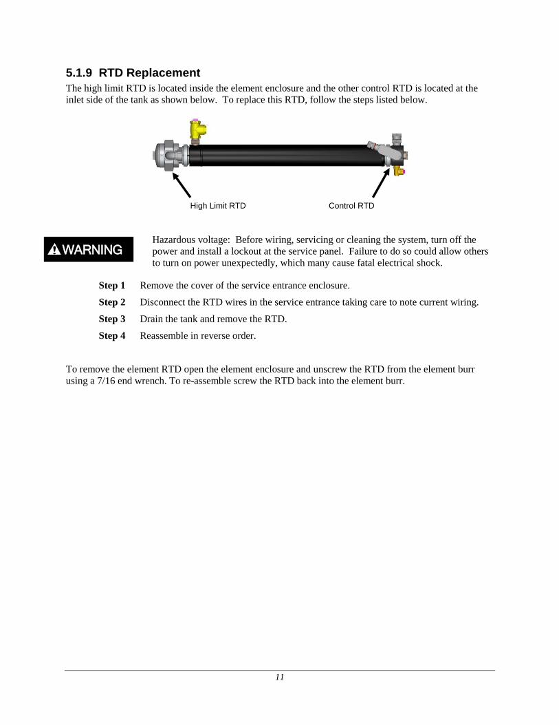
5.1.9 RTD Replacement
The high limit RTD is located inside the element enclosure and the other control RTD is located at the
inlet side of the tank as shown below. To replace this RTD, follow the steps listed below.
Hazardous voltage: Before wiring, servicing or cleaning the system, turn off the
power and install a lockout at the service panel. Failure to do so could allow others
to turn on power unexpectedly, which many cause fatal electrical shock.
Step 1 Remove the cover of the service entrance enclosure.
Step 2 Disconnect the RTD wires in the service entrance taking care to note current wiring.
Step 3 Drain the tank and remove the RTD.
Step 4 Reassemble in reverse order.
To remove the element RTD open the element enclosure and unscrew the RTD from the element burr
using a 7/16 end wrench. To re-assemble screw the RTD back into the element burr.
Control RTD High Limit RTD
12
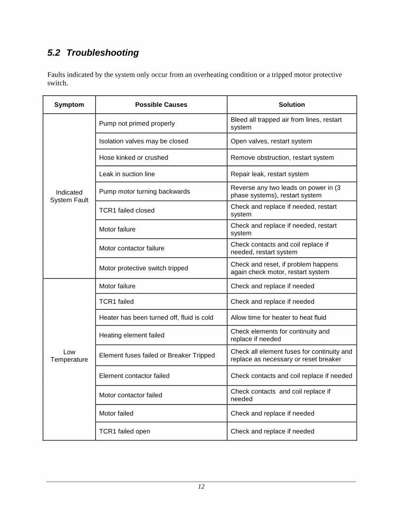
5.2 Troubleshooting
Faults indicated by the system only occur from an overheating condition or a tripped motor protective
switch.
Symptom Possible Causes Solution
Indicated System Fault
Pump not primed properly Bleed all trapped air from lines, restart system
Isolation valves may be closed Open valves, restart system
Hose kinked or crushed Remove obstruction, restart system
Leak in suction line Repair leak, restart system
Pump motor turning backwards Reverse any two leads on power in (3 phase systems), restart system
TCR1 failed closed Check and replace if needed, restart system
Motor failure Check and replace if needed, restart system
Motor contactor failure Check contacts and coil replace if needed, restart system
Motor protective switch tripped Check and reset, if problem happens again check motor, restart system
Low Temperature
Motor failure Check and replace if needed
TCR1 failed Check and replace if needed
Heater has been turned off, fluid is cold Allow time for heater to heat fluid
Heating element failed Check elements for continuity and replace if needed
Element fuses failed or Breaker Tripped Check all element fuses for continuity and replace as necessary or reset breaker
Element contactor failed Check contacts and coil replace if needed
Motor contactor failed Check contacts and coil replace if needed
Motor failed Check and replace if needed
TCR1 failed open Check and replace if needed


![Proposed Namstey Tower In Mumbai - 300m]]](https://static.documents.pub/doc/80x56/577d2e911a28ab4e1eaf670d/proposed-namstey-tower-in-mumbai-300m.jpg)


