Page 1
VTT TECHNICAL RESEARCH CENTRE OF FINLAND LTD
Oil Detection among Ice and Snow –
Lessons learned
Arctic Oil Recovery Exercise “Kemi Arctic 2015”
Jukka Sassi, VTT
Jorma Rytkönen, Finnish Environmental Institute SYKE
24 March, 2015
Photo: J. Sassi, VTT
Page 2
224 March, 2015 2
Content
Oil detection in arctic conditions
Overview of oil detection sensor technology
Deployment platforms
R&D activities in surveillance technology
Conclusions
Announcement of the field test trials of novel sensor technology in 2016
KEMI ARCTIC 2015
Jukka Sassi, VTT & Jorma Rytkönen, SYKE
Page 3
324 March, 2015 3
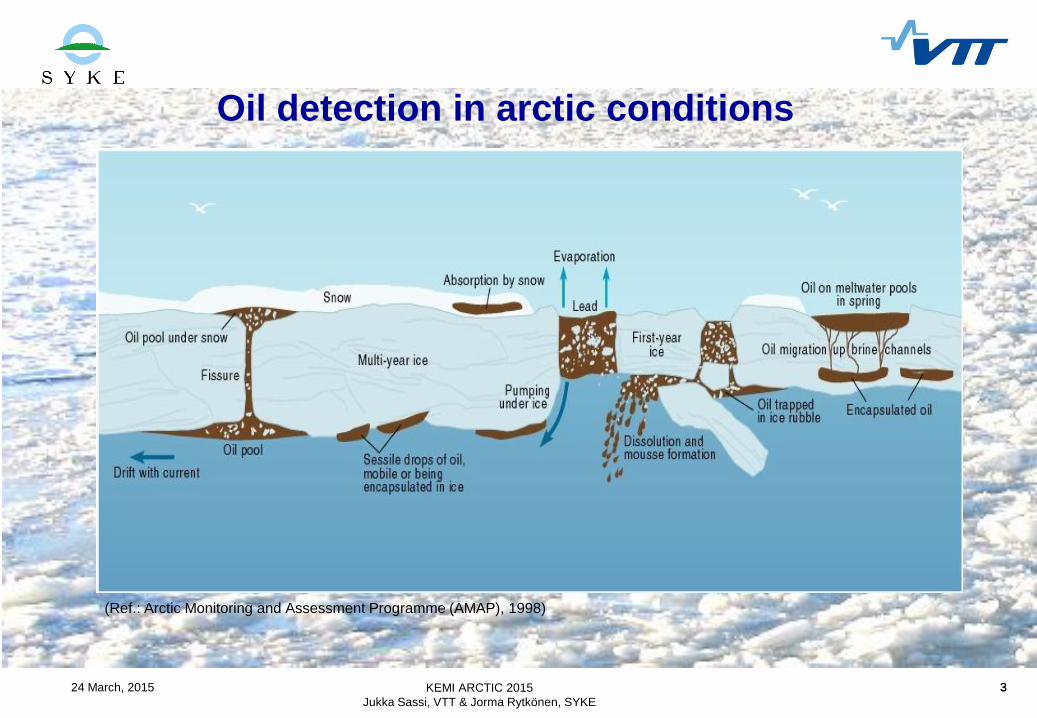
Oil detection in arctic conditions
KEMI ARCTIC 2015
Jukka Sassi, VTT & Jorma Rytkönen, SYKE
(Ref.: Arctic Monitoring and Assessment Programme (AMAP), 1998)
Page 4
424 March, 2015 4
Recognised oil detection sensor technologies
• Extensive studies conducted by SINTEF in Oil In Ice – JIP and in Arctic Oil Spill
Response Technology Joint Industry Programme (JIP) and recent R&D Finland in sensor
technology
• Passive optical sensors: cameras and multispectral imaging systems, ultraviolet (UV) and
Near-InfraRed (NIR) sensors, hyperspectral sensors
• Passive Thermal InfraRed sensors (TIRs) and MicroWave Radiometer (MWR) systems
• Active radar sensors: Side-Looking Airborne Radar (SLAR) and (Synthetic Aperture radar
(SAR) systems, Marine Radar, Ground Penetrating Radar (GPR)
• Active Laser and fluorosensors: fluorosensors, Tunable Diode Laser Spectroscopy
(TDLS), Laser-Ultrasonic Remote Sensing of Oil Thickness (LURSOT), Light Detection
and Ranging LiDAR
• Experimental sensors: Acoustic Sensors, Nuclear Magnetic Resonance (NMR)
Spectroscopy, trained dogs
KEMI ARCTIC 2015
Jukka Sassi, VTT & Jorma Rytkönen, SYKE
Page 5
524 March, 2015 5
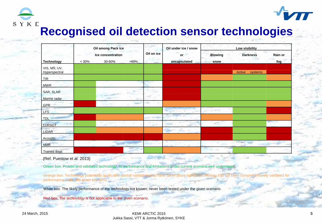
Recognised oil detection sensor technologies
KEMI ARCTIC 2015
Jukka Sassi, VTT & Jorma Rytkönen, SYKE
Oil among Pack Ice
Oil on ice
Oil under ice / snow Low visibility
Ice concentration or Blowing Darkness Rain or
Technology < 30% 30-60% >60% encapsulated snow fog
VIS, MS, UV,
Hyperspectral Active systems
TIR
MWR
SAR, SLAR
Marine radar
GPR
LFS
TDL
LURSOT
LIDAR
Acoustic
NMR
Trained dogs
Green box: Proven and validated technology, its performance and limitations under current scenario well understood.
Orange box: Technology potentially applicable, partial validation may have taken place but the technology has not been comprehensively validated for
performance under the given scenario.
White box: The likely performance of the technology not known; never been tested under the given scenario.
Red box: The technology is not applicable to the given scenario.
(Ref. Puestow et al. 2013)
Page 6
624 March, 2015 6
Recognised oil detection sensor technologies
KEMI ARCTIC 2015
Jukka Sassi, VTT & Jorma Rytkönen, SYKE
Platform Ice surface AUV Shipborne Airborne Satellite
Sensor Dogs GPR SonarMarine
radarFLIR GPR Visible UV FLIR SLAR SAR
OIL ON ICE
Exposed on cold ice surface Y N/A N/A N Y Y Y N Y N N
Exposed on spring melt pools Y N/A N/A ? Y N Y ? Y ? N
Buried under snow Y Y N/A N/A N Y N N N N N
OIL UNDER ICE
Smooth fast ice ? Y Y N/A N/A Y N/A N/A N/A N N
Deformed pack ice ? ? Y N/A N/A ? N/A N/A N/A N N
OIL IN ICE
Discrete encapsulated layer ? Y N N/A N/A Y N/A N/A N/A N N
Diffuse vertical saturation ? ? N N/A N/A ? N/A N/A N/A N N
OIL BETWEEN ICE FLOES
1 - 3/10 concentration N/A N/A N Y Y N Y Y Y Y Y
4 - 6/10 concentration N N/A N ? Y N Y ? Y ? ?
7 - 9/10 concentration ? N/A N N Y N Y N Y N N
(Ref. Dickins, 2010)LEGEND
Likely Y
Possible ?
Not likely N
Not applicable N/A
Blocked by dark/cloud/fog/precip.
Page 7
724 March, 2015 7
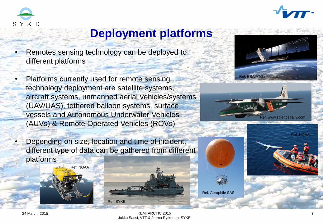
Deployment platforms
• Remotes sensing technology can be deployed to
different platforms
• Platforms currently used for remote sensing
technology deployment are satellite systems,
aircraft systems, unmanned aerial vehicles/systems
(UAV/UAS), tethered balloon systems, surface
vessels and Autonomous Underwater Vehicles
(AUVs) & Remote Operated Vehicles (ROVs)
• Depending on size, location and time of incident,
different type of data can be gathered from different
platforms
KEMI ARCTIC 2015
Jukka Sassi, VTT & Jorma Rytkönen, SYKE
Ref. www.sciencedaily.com
Ref. ESA/ATG medialab
Ref. NOAA
Ref. Aerophile SAS
Ref. SYKE
Ref. NOAA
Page 8
824 March, 2015 8
Satellite Systems
KEMI ARCTIC 2015
Jukka Sassi, VTT & Jorma Rytkönen, SYKE
Advantages Disadvantages
Can potentially cover a large area in a
short period of time
The timing and frequency of overpasses by
satellite systems may not be optimal for the
situation
Data may potentially be transmitted via the
internet almost immediately
Clear skies are needed to perform optical work
Many radar satellites are useful in
detecting large offshore spills and spotting
anomalies
The probability of detecting oil may be low
Some operational commercial satellites
can be tasked to respond to emergencies
within a range of 90 minutes to 4 hours
Developing algorithms to highlight oil slicks is
difficult
Extensive time may be required to convert data
into actionable information
(Image: RADARSAT-2 Data
and Products © MacDONALD,
DETTWILER AND
ASSOCIATES LTD. (2011)
Page 9
924 March, 2015 9
Aircraft Systems
KEMI ARCTIC 2015
Jukka Sassi, VTT & Jorma Rytkönen, SYKE
Advantages Disadvantages
Large areas can be surveyed in a relatively short
time frame
Weather and daylight/darkness must be suitable for the
type of aircraft and sensors being utilized
Aircraft are usually available on short notice and can
be more cost effective
Safety margins for operation need to be determined and
adhered to. Regional flight rules may dictate operating
conditions
Most types of remote sensors can be deployed on
aircraft
Remote sensing equipment should be in a “universal”
package that can be deployed on any type of aircraft
Multiple sensor types may be deployed on a single
aircraft
Some remote sensing equipment too bulky and can be
used only from the dedicated aircraft
Aircraft usually have multiple navigation aids that can
assist in pinpointing locations
Remote sensing operation must be coordinated with
other aircraft activities (e.g. overflight, dispersant,
observer
Remote sensing package must have the necessary
method of data capture and communications
Ref.: www.raja.fi
Page 10
1024 March, 2015 10
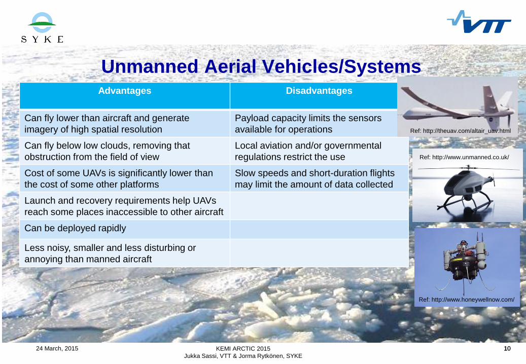
Unmanned Aerial Vehicles/Systems
KEMI ARCTIC 2015
Jukka Sassi, VTT & Jorma Rytkönen, SYKE
Advantages Disadvantages
Can fly lower than aircraft and generate
imagery of high spatial resolution
Payload capacity limits the sensors
available for operations
Can fly below low clouds, removing that
obstruction from the field of view
Local aviation and/or governmental
regulations restrict the use
Cost of some UAVs is significantly lower than
the cost of some other platforms
Slow speeds and short-duration flights
may limit the amount of data collected
Launch and recovery requirements help UAVs
reach some places inaccessible to other aircraft
Can be deployed rapidly
Less noisy, smaller and less disturbing or
annoying than manned aircraft
Ref: http://theuav.com/altair_uav.html
Ref: http://www.unmanned.co.uk/
Ref: http://www.honeywellnow.com/
Page 11
1124 March, 2015 11
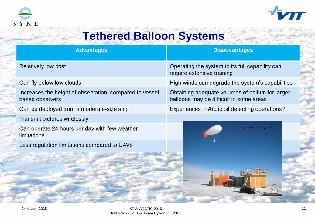
Tethered Balloon Systems
KEMI ARCTIC 2015
Jukka Sassi, VTT & Jorma Rytkönen, SYKE
Advantages Disadvantages
Relatively low cost Operating the system to its full capability can
require extensive training
Can fly below low clouds High winds can degrade the system’s capabilities
Increases the height of observation, compared to vessel-
based observers
Obtaining adequate volumes of helium for larger
balloons may be difficult in some areas
Can be deployed from a moderate-size ship Experiences in Arctic oil detecting operations?
Transmit pictures wirelessly
Can operate 24 hours per day with few weather
limitations
Less regulation limitations compared to UAVs
Source: SPEC Inc.
Page 12
1224 March, 2015 12
Surface vessels
KEMI ARCTIC 2015
Jukka Sassi, VTT & Jorma Rytkönen, SYKE
Advantages Disadvantages
Increased interface with the thickest oil based on
remote sensing data and visual means
Limited to small coverage areas in the immediate
vicinity of the vessel
Versatile and can be manoeuvred to remain in desired
location
Limited usefulness in high seas due to sensor
movement at the high point of the vessel.
Instrumentation and sensors can easily be changed to
meet needs and weather conditions
Some oil combating technologies (e.g. booms, arms)
have limited operational capabilities in high seas and/or
in harsh ice conditions
The probability of detecting oil is very high Heavy ice conditions limit the operational operational
capabilities of smaller vessels
Human presence on manned vessels enables the
presence of oil to be validated by visual means
Can provide a much longer “time on station” (e.g.
hours to days) in the area of intent for observations
grouped with other platforms
Oil recovery vessel Halli. Photo: Syke
Page 13
1324 March, 2015 13
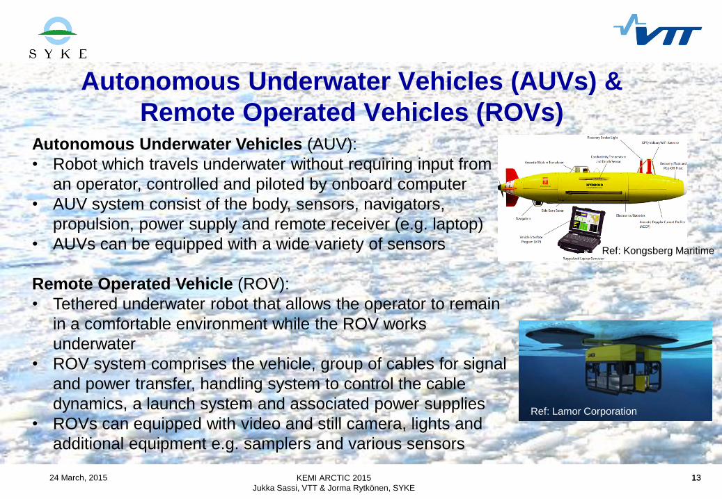
Autonomous Underwater Vehicles (AUVs) &
Remote Operated Vehicles (ROVs)
KEMI ARCTIC 2015
Jukka Sassi, VTT & Jorma Rytkönen, SYKE
Autonomous Underwater Vehicles (AUV):
• Robot which travels underwater without requiring input from
an operator, controlled and piloted by onboard computer
• AUV system consist of the body, sensors, navigators,
propulsion, power supply and remote receiver (e.g. laptop)
• AUVs can be equipped with a wide variety of sensors
Remote Operated Vehicle (ROV):
• Tethered underwater robot that allows the operator to remain
in a comfortable environment while the ROV works
underwater
• ROV system comprises the vehicle, group of cables for signal
and power transfer, handling system to control the cable
dynamics, a launch system and associated power supplies
• ROVs can equipped with video and still camera, lights and
additional equipment e.g. samplers and various sensors
Ref: Kongsberg Maritime
Ref: Lamor Corporation
Page 14
1424 March, 2015 14
Autonomous underwater vehicles (AUVs) and
Remote Operated Vehicle (ROVs)
KEMI ARCTIC 2015
Jukka Sassi, VTT & Jorma Rytkönen, SYKE
Advantages Disadvantages
Operational time limited only by operators (ROVs) and
battery power (UAVs)
Limited experiences in ice conditions
Can be used for oil detection under ice when equipped with
e.g. sonar sensors
Cables may cause severe problems when operated
in rough ice conditions
Highly manoeuvrable and can cover wide surveillance areas Equipment quite expensive
Allows detailed examination of target area Requires reliable and robust communication platform
Depth range limited by the length of umbilical cable (ROVs)
and battery capacity (AUVs)
Operation requires trained persons
Various systems available due to oil and gas exploration in
the Arctic
Effectiveness can be limited by water turbidity or
darkness (if adequate illumination not available)
Applications for underwater oil removal in design phase (i.e.
Lamor)
In case of lost equipment or accident, no loss of life
Page 15
1524 March, 2015 15KEMI ARCTIC 2015
Jukka Sassi, VTT & Jorma Rytkönen, SYKE
(Ref. Cardno Entrix, 2012)
Total Publications per PlatformAerial Platform Publications per Sensor [%]
Satellite Platform
Publications per Sensor [%]
Multiple Platform
Publications per Sensor [%]
Current R&D and emerging trends in
surveillance technology
Page 16
1624 March, 2015 16
Conclusions – Lessons Learned (1/2)
KEMI ARCTIC 2015
Jukka Sassi, VTT & Jorma Rytkönen, SYKE
• Flexible combination of sensors operating from aircraft, helicopters, vessels,
satellites and the ice surface are recommended for future Arctic oil spill
emergency preparedness.
• Most useful remote sensors and systems for spills in ice are expected to be
aircraft and vessel-based FLIR for oil on the surface in a broad range of ice
concentrations, trained dogs on solid ice, GPR operated from helicopters and
the ice surface for oil under snow or trapped in the ice, and SLAR and satellite-
based SAR for large slicks on the water in very open ice covers.
• Current generation of all-weather SAR satellites can play a valuable support role
in mapping detailed ice conditions and directing marine resources.
• Existing commercial GPR systems can be used from low-flying helicopter to
detect oil trapped under snow on the ice and to detect oil trapped under solid ice.
Page 17
1724 March, 2015 17
Conclusions – Lessons Learned (2/2)
KEMI ARCTIC 2015
Jukka Sassi, VTT & Jorma Rytkönen, SYKE
• Detecting isolated oil patches trapped among closely packed ice floes is major
challenge with any current remote sensing system, especially during periods of
extended darkness, low clouds or fog. The most effective solution is to deploy closely
spaced GPS tracking buoys to follow the ice and the oil.
• Trained dogs can reliably detect very small oil volumes and map oiled boundaries on
solid ice and in sediments on Arctic shorelines under extreme weather conditions.
• New technologies may enhance the ability to detect oil over a broader range of Arctic
spill scenarios in the near future. These include NMR, UAVs, AUVs and next
generation GPR optimised for the oil in ice problem.
• The optimum mix of remote sensing technologies depends heavily on the spill
characteristic and prevailing weather and ice conditions.
• Arctic spill contingency plans need to account for the operational constraints of aircraft
and helicopter endurance, weather and the likelihood of competing demands in limited
remote sensing resources.
Page 18
1824 March, 2015 18
Oil detection in Arctic conditions -
Planned Field Experiments in Finland 2016
KEMI ARCTIC 2015
Jukka Sassi, VTT & Jorma Rytkönen, SYKE
• SYKE had a plan to test UAV’s and sensors in March
2015 in Kotka. Tests were postponed due to too
warm environmental conditions.
• New plan is to perform tests in 2016 and study
sensors and oil early warning systems in ice and
snow
• Deployment Platforms: aircrafts, UAVs, in-situ
measuring units
• Sensor technologies: To be defined
• Location: Northern Finland
• Expected time: January – March 2016
Page 19
1924 March, 2015 19
Abbreviations
KEMI ARCTIC 2015
Jukka Sassi, VTT & Jorma Rytkönen, SYKE
. AUV Autonomous Underwater Vehicle MS Multi-Spectral
DWH DeepWater Horizon MWR Microwave Radiometer
FLIR Forward Looking InfraRed NMR Nuclear Magnetic Resonance
GIS Geographic Information System SAR Synthetic Aperture Radar
GPR Ground Penetrating Radar SLAR Side-Looking Airborne Radar
LFS Laser Fluorosensor TDLS Tunable Diode Laser Spectroscopy
LiDAR Light Detection and Ranging TIR Thermal InfraRed
FLIR Forward-Looking InfraRed UAV Unmanned Aerial Vehicle
LFS Laser Fluorosensor UAS Unmanned Aerial System
LURSOT Laser-Ultrasonic Remote Sensing UV UltraViolet
of Oil Thickness VIS Visible
Page 20
2024 March, 2015 20
Selected References
KEMI ARCTIC 2015
Jukka Sassi, VTT & Jorma Rytkönen, SYKE
American Petroleum Institute (API). 2013. Remote Sensing in Support of Oil Spill Response. Planning Guidance. API Technical Report.
September 2013.
Arctic Monitoring and Assessment Programme (AMAP), 1998. AMAP Assessment Report: Arctic Pollution Issues. Arctic Monitoring and
Assessment Programme (AMAP), Oslo, Norway.
Dickins, D. (editor, DF Dickins Associates LLC). 2010. Project P5: Remote Sensing Summary Report. Oil in Ice – JIP. SINTEF Materials and
Chemistry. 24.05.2010. Report no. 30.
Partington, Kim. 2014. An Assessment of Surface Surveillance Capabilities for Oil Spill Re-sponse using Airborne Remote Sensing. Polar
Imaging Limited. 21 May 2014. PIL-4000-38-TR-1.0
Puestow, T.; Parsons, L; Zakharov, I.; Cater, N.; Bobby, P.; Fuglem, M.; Parr, G.; Jayasiri, A. and Warren, S. (C-CORE), Warbanski, G.
(Emergency Spill and Consulting Inc.). 2013. Oil Spill Detection and Mapping in Low Visibility and Ice: Surface Remote Sensing. Final Report
5.1, 15 October 2013. Arctic Oil Spill Response Technology Joint Industry Programme (JIP).
Sørstrøm, S., Brandvik, J., Buist, I., Daling, P., Dickins, D., Faksness, L-G., Potter, S., Ras-mussen, J., Singsaas, I. 2010. Joint industry
program on oil spill contingency for Arctic and ice-covered waters. Summary report. Oil in Ice – JIP, Report no 32. SINTEF Materials and
Chemistry, Marine Environmental Technology. 10.04.2010.
Limnaios, G. 2014. Current Usage of Unmanned Aircraft Systems (UAS) and Future Chal-lenges: A Mission Oriented Simulator for UAS as a
Tool for Design and Performance Evalua-tion. Journal of Computations & Modelling, vol.4, no.1, 2014, 167-188. ISSN: 1792-7625 (print), 1792-
8850 (online). Scienpress Ltd, 2014.
Cardno Entrix. 2012. Surveillance Technologies for Oil Spill Response. Current Research and Emerging Trends.
Page 21
Thank You!
Further Information
[email protected] & [email protected]