1 References 1- Cengel, Yunus A. and Michael A. Boles, Thermodynamics - An Engineering Approach, 5th ed., New York, McGraw- hill:2006. 2- T. D. Eastop and McConkey, Applied Thermodynamics for Engineering Technologists, 3rd edit., Longman Inc., New York: 1978 & 5 edit. 1993. 3- R.K. Rajput ,Engineering Thermodynamics,3 rd edition, Laxmi Publications (P) Ltd, New Delhi,2007 Oil Engineering Dept. Thermodynamics Second Stage Asst. Lect. Saad H. Saadoon Messan University
Transcript
1
References
1- Cengel, Yunus A. and Michael A. Boles, Thermodynamics -
An Engineering Approach, 5th ed., New York, McGraw-
hill:2006.
2- T. D. Eastop and McConkey, Applied Thermodynamics for
Engineering Technologists, 3rd edit., Longman Inc., New
York: 1978 & 5 edit. 1993.
3- R.K. Rajput ,Engineering Thermodynamics,3rd
edition,
Laxmi Publications (P) Ltd, New Delhi,2007
Oil Engineering Dept.
Thermodynamics
Second Stage
Asst. Lect. Saad H. Saadoon
Messan University
2
Thermodynamics
1.Basic concepts
Definition of Thermodynamics
The name thermodynamics stems from the Greek words therme (heat) and
dynamis (power), which is most descriptive of the early efforts to convert
heat into power.
Thermodynamics may be defined as follow:
_ Thermodynamics is an axiomatic science which deals with the relations
among heat, work and properties of system which are in equilibrium. It
describes state and changes in state of physical systems.
Thermodynamics basically entails four laws or axioms known as Zeroth,
First, Second and Third law of thermodynamics.
_ The First law throws light on concept of internal energy.
_ The Zeroth law deals with thermal equilibrium and establishes a concept
of temperature.
_ The Second law indicates the limit of converting heat into work and
introduces the principle of increase of entropy.
_ The Third law defines the absolute zero of entropy.
These laws are based on experimental observations and have no
mathematical proof. Like all physical laws, these laws are based on logical
reasoning.
3
1. A system is defined as a quantity of matter or a region in space chosen for
study.
2. Surroundings: The mass or region outside the system.
3. Boundary: The real or imaginary surface that separates the system from
its surroundings.. The boundary of a system can be fixed or movable.fig 1.1
4. A closed system (also known as a control mass) consists of a fixed
amount of mass, and no mass can cross its boundary.fig 1.2
5. An open system, or a control volume, as it is often called, is a properly
selected region in space. It usually encloses a device that involves mass flow
such as a compressor, turbine, or nozzle. Both mass and energy can cross the
boundary of a control volume. Fig. 1-3
.
Fig (1.1) system, surrounding,
boundary
Fig (1.2) closed system
4
Fig. 1-3 open system
6. Extensive and Intensive properties:
Extensive – the property value for the system is the sum of the values of the
parts into which the system is divided (depends on the system size) e.g.,
mass, volume, energy
Intensive – the property is independent of system size (value may vary
throughout the system), e.g., pressure, temperature fig 1-4
Fig(1-4) Intensive and Extensive properties
Fig. 1–4
5
Extensive properties per unit mass are called specific properties. Some
examples of specific properties are specific volume (v = V/m) and specific
total energy (e = E/m).
7. Density and Specific gravity
Density is defined as mass per unit volume.
1
The reciprocal of density is the specific volume v, 2
Specific gravity, or relative density: is defined as the ratio of the density of
a substance to the density of some standard substance at a specified
temperature (usually water at 4°C, for which ρ = 1000 kg/m3). That is,
3
The weight of a unit volume of a substance is called specific weight and
is expressed as 4
8. Thermodynamic equilibrium and State
Thermodynamic equilibrium is a situation in which thermodynamic
system does not undergo any change in its state.
Let us consider a steel glass full of hot milk kept in open atmosphere. It is
quite obvious that the heat from milk shall be continuously transferred to
atmosphere because the temperature of milk, glass and atmosphere are not
alike. During the transfer of heat from milk the temperature of milk could be
seen to decrease continually. Temperature attains some final value and does
not change any more. This is the equilibrium state at which the properties
stop showing any change in themselves. Fig(1-5)
6
System state: – condition of the thermodynamic system as described by its
properties (P1,T1,….).
A system is at steady-state if none of the system properties change with
time.
Fig(1-5) thermal equilibrium
9. Processes and Cycles
A process is the transformation of a system from one state to another state.
A cycle is a sequence of processes that begins and ends at the same state.
Example showing a cycle consisting of two processes fig (1-6)
Fig(1-6) Processes and Cycles
7
11. Pressure
Pressure is defined as a normal force exerted by a fluid per unit area, it
has the unit of Newtons per square meter (N/m2), which is called a pascal
(Pa). That is,
1 Pa = 1 N/m2
The other pressure unit commonly used in practice is bar
1 bar=105 Pa=0.1 Mpa=100 kPa
The actual pressure at a given position is called the absolute pressure,
and it is measured relative to absolute vacuum (i.e., absolute zero
pressure). Most pressure-measuring devices, however, are calibrated to
read zero in the atmosphere, and so they indicate the difference between
the absolute pressure and the local atmospheric pressure.
This difference is called the gage pressure. Pressures below atmospheric
pressure are called vacuum pressures.
Absolute, gage, and vacuum pressures are all positive quantities and are
related to each other by
Pgage=Pabs - Patm 5
Pvac= Patm - Pabs 6
11. Temperature
Temperature can be defined as a measure of “hotness” or “coldness,”
The commonly used mercury-in-glass thermometer, for example, is
based on the expansion of mercury with temperature.
Temperature Scales
The Kelvin scale is related to the Celsius scale by
T (K) = T (°C) + 273.15 7
8
The Rankine scale is related to the Fahrenheit scale by
T (R) = T (°F) + 459.67 8
It is common practice to round the constant in the above Eqs. are (273) and
(460) respectively.
The temperature scales in the two unit systems are related by
T (R) = 1.8 T (K) 9
T (°F) =1.8T (°C) + 32 10
A comparison of various temperature scales is given in Fig. (1-7)
Fig. (1-7) comparison of various temperature scales
Unites:
SI units will be used throughout our lectures: The international system of
units was adopted by General Conference of Weight and Measuring in 1960.
In SI units six physical quantities are arbitrarily assigned unit value and
hence all other physical quantities are derived from these. The six quantities
are as follows:
0 Absolute zero
32.02
°F R
273.16
°C K
-459.67 0 -273.15
0.01 491.69
9
Length Meter m
Mass Kilogram kg
Time Second s
Electric current Ampere I
Temperature Kelvin K
Luminous intensity Candela cd
Then for example, velocity = length/time has units m/s, acceleration =
velocity/time has units m/s2 , volume = length x length x length has units of
m3 and so on.
Working Substance: it is a matter contained within a the boundaries of the
system can be liquid, vapour or gas.
At any instant the state of the working substance may be define by certain
characteristics called properties such as temperature ( T ), pressure (p ),
specific volume ( ), internal energy ( E ), enthalpy ( h ) and entropy (s). It
has ben found that, for any pure working substance, only two independent
properties suffice to define completely the state of the fluid.
11
2. Heat and Work
Heat
When two systems at different temperatures are brought into contact
there are observable changes in some of their properties and changes
continue till the two don’t attain the same temperature if contact is
prolonged. Thus, there is some kind of energy interaction at the boundary
which causes change in temperatures. This form of energy interaction is
called heat. Heat is defined as the form of energy that is transferred between
two systems (or a system and its surroundings) by virtue of a temperature
difference
The heat transfer to the system is assigned with positive (+) sign while the
heat transfer from the system is assigned with negative (–) sign.
The science of thermodynamics deals with the amount of heat transfer as a
system undergoes a process from one equilibrium state to another, and
makes no reference to how long the process will take. But in engineering, we
are often interested in the rate of heat transfer, which is the topic of the
science of heat transfer.
Heat can be transferred in three different modes: conduction, convection,
and radiation. All modes of heat transfer require the existence of a
temperature difference, and all modes are from the high-temperature
medium to a lower-temperature one. Below we give a brief description of
each mode.
I-CONDUCTION Conduction is the transfer of energy from the more energetic particles of a
substance to the adjacent less energetic ones as a result of interactions
11
between the particles. Conduction can take place in solids, liquids, or gases
as shown in Fig (2-1)
. Conduction law is called Fourier’s law of heat conduction after J.
Fourier, who expressed it first in his heat transfer text in 1822.
1
Where:
is heat rate in kw
K is thermal conductivity of the material, which is a measure of the ability
of a material to conduct heat.
A is area and always normal to the direction of heat transfer.m2
is temperature difference in 0c
is in steady heat conduction through a large plane wall of thickness
Fig (2-1) Heat conduction through a large plane
wall of thickness Δx and area A.
12
II- CONVECTION
Convection is the mode of energy transfer between a solid surface and the
adjacent liquid or gas that is in motion, and it involves the combined effects
of conduction and fluid motion.fig (2-2). And is conveniently expressed by
Newton’s law of cooling as
2
Where:
h is the convection heat transfer coefficient in W/m2 · °C.
As is the surface area through which convection heat transfer takes place.m2
Ts is the surface temperature
T is the temperature of the fluid sufficiently far from the surface.
fig (2-2). Heat transfer by Convection
Convection is called forced convection if the fluid is forced to flow over the
surface by external means such as a fan, pump, or the wind. In contrast,
convection is called natural (or free) convection if the fluid motion is
caused by buoyancy forces that are induced by density differences due to the
variation of temperature in the fluid.
13
III- RADIATION In heat transfer studies we are interested in thermal radiation, which
is the form of radiation emitted by bodies because of their temperature.
The idealized surface that emits radiation at this maximum rate is called a
blackbody, and the radiation emitted by a blackbody is called blackbody
radiation (Fig. below). The radiation emitted by all real surfaces is less than
the radiation emitted by a blackbody at the same temperature, and is
expressed as given by the Stefan–Boltzmann law
3
Where:
Ɛ is the emissivity of the surface whose value is in the range ,
is the Stefan–Boltzmann constant.
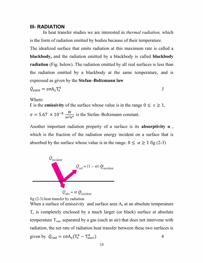
Another important radiation property of a surface is its absorptivity α ,
which is the fraction of the radiation energy incident on a surface that is
absorbed by the surface whose value is in the range. fig (2-3)
fig (2-3) heat transfer by radiation
When a surface of emissivity and surface area As at an absolute temperature
Ts is completely enclosed by a much larger (or black) surface at absolute
temperature Tsurr separated by a gas (such as air) that does not intervene with
radiation, the net rate of radiation heat transfer between these two surfaces is
given by
4
14
Gas Laws
Thermodynamic analysis relies largely upon the gas laws, which are known
as Boyle’s law (1662) and Charle’s law (1787).
Boyle’s law says that if temperature of a gas is held constant then its molar
volume is inversely proportional to the pressure. Mathematically it can be
related as p = constant.
Here p is the pressure and is the molar volume of gas, i.e. volume per
mole. Or (P1V1=P2V2) 4
Charle’s law says that for the pressure of gas held constant the volume of
gas is directly proportional to the temperature of gas. Mathematically it can
be given as /T = constant, where T is the temperature of the gas.
Or (V1/T1=V2/T2) 5
Ideal Gas
Engineering thermodynamics deals with different systems having gaseous
working fluids. Some gases behave as ideal gas and some as non-ideal gas.
In the range of practical interest, many familiar gases such as air, nitrogen,
oxygen, hydrogen, helium, argon, neon, krypton, and even heavier gases
such as carbon dioxide can be treated as ideal gases with negligible error
Equation of State
Any equation that relates the pressure, temperature, and specific volume of a
substance is called an equation of state.
There are several equations of state, some simple and others very complex. The
simplest and best-known equation of state for substances in the gas phase is the
ideal-gas equation of state. This equation predicts the P-v-T behavior of a gas
quite accurately within some properly selected region.
15
6
The gas constant R is different for each gas and is determined from
Where:
Ru is the universal gas constant and M is the molar mass (also called
molecular weight) of the gas. The constant Ru is the same for all substances,
and its value is
The molar mass M( can simply be defined as the mass of one kmol
(also called a kilogram-mole, abbreviated kgmol) in kilograms.
Real Gas
When a gas is found to disobey the perfect gas law, i.e. the equation of state
for ideal gas, then it is called ‘real gas’. Deviation of real gas from ideal gas
necessitates the suitable equation of state the ideal gas equation of state suits
the gas behaviour when intermolecular attraction and volume occupied by
the molecules themselves is negligibly small in reference to gas volume. At
high pressures intermolecular forces and volume of molecules both increase
and so the gas behaviour deviates from ideal gas to real gas. This deviation
from ideal-gas behavior at a given temperature and pressure can accurately
be accounted for by the introduction of a correction factor called the
compressibility factor Z defined as
Or 7
Z =1 for ideal gases. For real gases Z can be greater than or less than unity
16
Other Equations of State
The ideal-gas equation of state is very simple, but its range of applicability is
limited. It is desirable to have equations of state accurately over a larger
region with no limitations. Such equations are naturally more complicated.
Several equations have been proposed for this purpose we shall discuss only
three: the van der Waals equation because it is one of the earliest, the
Beattie-Bridgeman equation of state because it is one of the best known and
is reasonably accurate, and the Benedict-Webb-Rubin equation because it is
one of the more recent and is very accurate.
1-Van der Waals Equation of State
The van der Waals equation of state was proposed in 1873, and it has two
constants that are determined from the behavior of a substance at the critical
point. It is given by
8
Where:
The constants a and b can be determined for any substance from the critical
point data alone given in special tables
2-Beattie-Bridgeman Equation of State
The Beattie-Bridgeman equation, proposed in 1928, is an equation of state
based on five experimentally determined constants. It is expressed as
9
Where
The constants appearing in the above equation are given in tables
17
Benedict-Webb-Rubin Equation of State
Benedict, Webb, and Rubin extended the Beattie-Bridgeman equation in
1940 by raising the number of constants to eight. It is expressed as
…………………………………………………………………………...10
The values of the constants appearing in this equation are given in tables
Example1. A vessel of 5 m3 capacity contains air at 100 kPa and
temperature of 300K. Some air is removed from vessel so as to reduce
pressure and temperature to 50 kPa and 7ºC respectively. Find the amount
of air removed and volume of this mass of air at initial states of air. Take R
= 287 J/kg.K for air.
Solution:
The amount of air removed=
The volume of air removed
Example 2.Determine the pressure of 5 kg carbon dixoide contained in a
vessel of 2 m3 capacity at 27º C, considering it as perfect gas. The universal
gas constant Ru=8.314
, molecular weight of co2 =44.01
Solution
18
Example 3.A vessel has two compartments ‘A’ and ‘B’ as shown with
pressure gauges mounted on each compartment. Pressure gauges of A and B
read 400 kPa and 150 kPa respectively. Determine the absolute pressures
existing in each compartment if the local barometer reads 720 mm Hg.
19
Work
Work is the energy transfer associated with force acting through a
distance. In thermodynamics the work can be defined as follows:
“Work shall be done by the system if the total effect outside the system is
equivalent to the raising of weight and this work shall be positive work”.
In above definition the work has been defined as positive work and says that
there need not be actual raising of weight but the effect of the system
behaviour must be reducible to the raising of a weight and nothing else. Its
units are N. m or Joule. Let us look at a piston cylinder mechanism (closed
system), where high pressure air is filled inside the cylinder fitted with a
piston exerting force against some resistance. As the piston moves a distance
say ‘l’, the work would be done. It can be reduced to the raising of weight by
replacing this resisting system by a frictionless pulley and lever such that a
weight W is raised.
From the thermodynamic definition of work the sign convention established
as positive work shall be the one which is done by the system while the
negative work shall be the one that is done upon the system. Fig(2-4)
Fig(2-4) the work
21
If the gas is made to expand due to heating, the piston shall undergo
displacement and say the piston displacement is dx. If the force exerted by
gas on face of piston is F and the cross section area of piston is A, then the
displacement work done may be given by:
dW = F · dx
For the gas pressure being p, the force may be given by F = p · A.
Substituting for F,
dW = p · A · dx
or, dW = p · dV, where dV is the elemental change in volume or the
volumetric displacement. If the total displacement of piston is given by L
then the total work can be had by integrating the above dW with respect to x
for displacement L, or with respect to volume for volume change.
The zeroth Law of Thermodynamics
If two bodies are separately in thermal equilibrium with a third body
then they must be in thermal equilibrium with each other.
A B A C B C
Thermal equilibrium Thermal equilibrium Also in thermal equilibrium
21
3. The First Law of Thermodynamics
The concept of energy and the hypothesis that it can be neither created
nor destroyed, this is the Principle of the Conservation of Energy. The
first law of thermodynamics is merely one statement of this general
principle with particular reference to heat energy and work.
The First Law of thermodynamics can be stated as follows:
When a system under goes a thermodynamics cycle then the net heat
supplied to the system from its surroundings is equal to the net work done
by the system on its surroundings.
In symbols:
dWdQ
Where: represent the sum for a complete cycle.
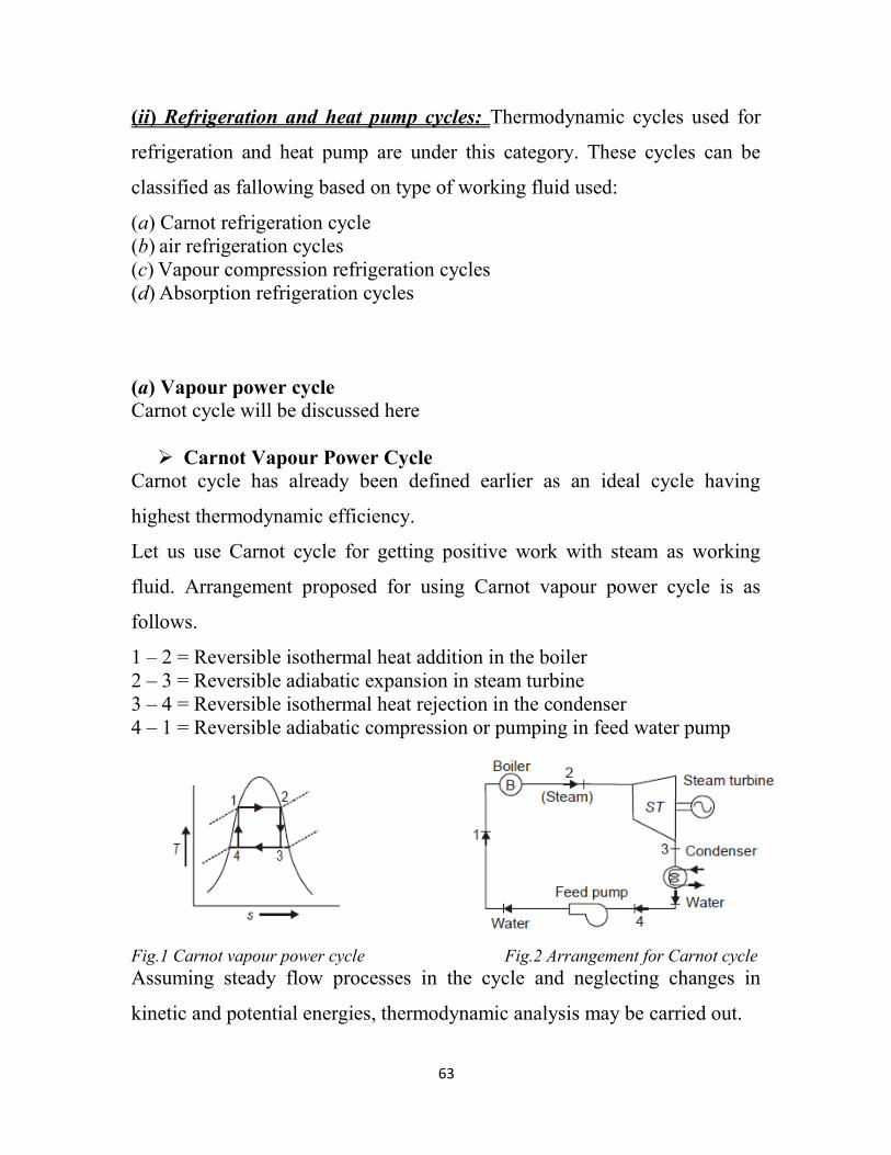
I-The Steady Flow Energy Equation
This equation is a mathematical statement of the principle of the
conservation of energy as applied to the flow of fluid through a
thermodynamic system.fig (3-1)
The various forms of energy which fluid can have are as follow:
a- Potential Energy: PE
If the fluid is at some height Z above a given datum level, then, as a
result of its mass it possesses potential energy with respect to that
datum. Thus, for unit mass of fluid, in the close vicinity of the earth
Potential energy = g.Z
b- Kinetic Energy: KE
If the fluid is in motion then it possesses kinetic energy. If the fluid is
lowing with velocity C then, for unit mass of fluid,
Kinetic energy = 2
2C
c- Internal Energy: U
It is the energy stored within a fluid which results from the internal
motion of its atoms and molecules.
22
All fluids store energy. The store of energy within any fluid can be
increased or decreased as the result of various processes carried out on
or by the fluid. If the internal energy of unit mass of fluid is being
discussed this is called the specific internal energy by u.
d- Flow or Displacement Energy: DE
Any volume of fluid entering or leaving a system must displace an
equal volume ahead of itself in order to enter or leave the system.
Displacement energy = Pv
e- Heat Received or Rejected: q
During its passage through the system the fluid can have a direct
reception or rejection of heat energy through the system boundary. This
is designated by q. Thus if
Heat is received then q is +ve
Heat is rejected then q is –ve
Heat is neither received nor rejected then q = 0
f- External Work Done: w
During its passage through the system the fluid can do external work or
have external work done on it. This is designated by w.
External work is done by the fluid then w is +ve
External work is done on the fluid then w is -ve
If no external work is done on or by the fluid then w =0
Applying the principle of conservation of energy to the system, then,
Total energy entering the system = Total energy leaving the system
Or, for unit mass of substance,
P1,v1,u1,C1 w
Entry
P2,v2,u2,C2
Q System Z2 Exit
Z1
DATUM LEVEL fig (3-1) the steady flow energy equation in control volume
23
wCvPugZqCvPugZ 2
22222
2
111112
1
2
1
11
This called the Steady Flow Energy Equation
In equation 1 this particular combination actually appears as follows,
wCvPugZqCvPugZ 2
22222
2
111112
1)(
2
1)(
let vPuh 1
Enthalpy (H) of a substance at any point is quantification of energy content
in it, which could be given by summation of internal energy and flow
energy.
Or per unit mass
From this then, it will be noted that the steady floe energy equation can
also be written,
wChgZqChgZ 2
222
2
1112
1
2
1
12
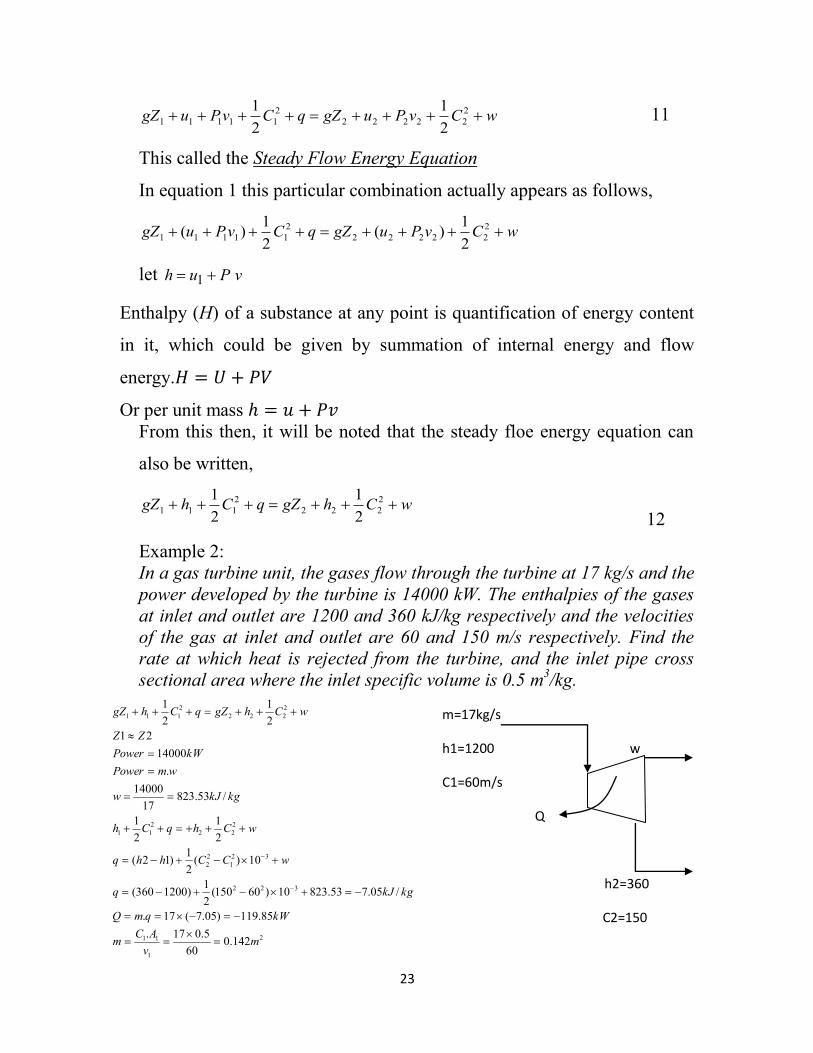
Example 2:
In a gas turbine unit, the gases flow through the turbine at 17 kg/s and the
power developed by the turbine is 14000 kW. The enthalpies of the gases
at inlet and outlet are 1200 and 360 kJ/kg respectively and the velocities
of the gas at inlet and outlet are 60 and 150 m/s respectively. Find the
rate at which heat is rejected from the turbine, and the inlet pipe cross
sectional area where the inlet specific volume is 0.5 m3/kg.
m=17kg/s
h1=1200 w
C1=60m/s
Q
h2=360
C2=150 2
1
11
322
32
1
2
2
2
22
2
11
2
222
2
111
142.060
5.017.
85.119)05.7(17.
/05.753.82310)60150(2
1)1200360(
10)(2
1)12(
2
1
2
1
/53.82317
14000
.
14000
21
2
1
2
1
mv
ACm
kWqmQ
kgkJq
wCChhq
wChqCh
kgkJw
wmPower
kWPower
ZZ
wChgZqChgZ
24
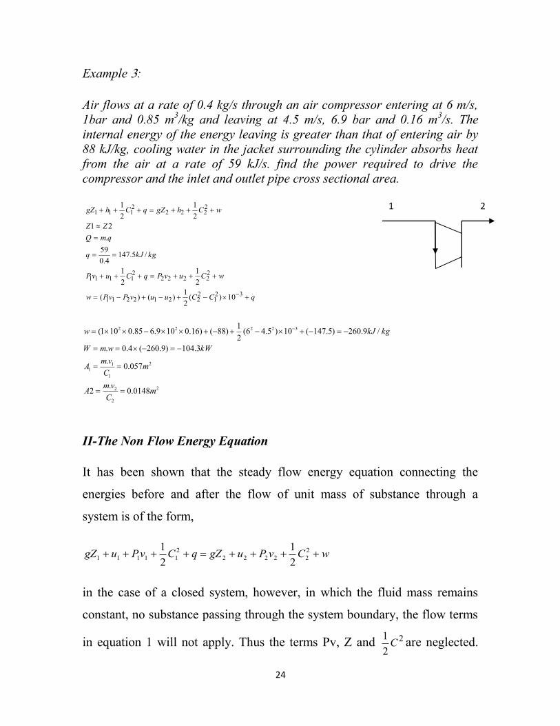
Example 3:
Air flows at a rate of 0.4 kg/s through an air compressor entering at 6 m/s,
1bar and 0.85 m3/kg and leaving at 4.5 m/s, 6.9 bar and 0.16 m
3/s. The
internal energy of the energy leaving is greater than that of entering air by
88 kJ/kg, cooling water in the jacket surrounding the cylinder absorbs heat
from the air at a rate of 59 kJ/s. find the power required to drive the
compressor and the inlet and outlet pipe cross sectional area.
2
2
2
2
1
11
32222
0148.0.
2
057.0.
3.104)9.260(4.0.
/9.260)5.147(10)5.46(2
1)88()16.0109.685.0101(
mC
vmA
mC
vmA
kWwmW
kgkJw
II-The Non Flow Energy Equation
It has been shown that the steady flow energy equation connecting the
energies before and after the flow of unit mass of substance through a
system is of the form,
wCvPugZqCvPugZ 2
22222
2
111112
1
2
1
in the case of a closed system, however, in which the fluid mass remains
constant, no substance passing through the system boundary, the flow terms
in equation 1 will not apply. Thus the terms Pv, Z and 2
2
1C are neglected.
1 2
qCCuuvPvPw
wCuvPqCuvP
kgkJq
qmQ
ZZ
wChgZqChgZ
321
22212211
22222
21111
2222
2111
10)(2
1)()(
2
1
2
1
/5.1474.0
59
.
21
2
1
2
1
25
The system is then to be non-flow. Thus from equation 1, the energy
equation for the non-flow case becomes,
wuqu 21
from which
wuuq )( 12 The non-flow energy equation or simple energy
equation
this is often written
massunit for is This uwq
General Notes
Steady flow energy equation can be written as:
1102
11010
2
110 32
22223
232
11113
1 wCvPugZqCvPugZ
Z1,Z1 Inlet and out let height m
C1, C2 Inlet and outlet velocity m/s
P1, P2 Inlet and outlet pressure kPa
2&1 vv Inlet and outlet specific volume m3/kg
u1&u2 Inlet and outlet internal energy kJ/kg
q Heat received or rejected kJ/kg
w Work done by or on the system kJ/kg
III-Unsteady Flow Energy Equation (U.S.F.E.E.)
During a steady-flow process, no changes occur within the control volume.
Many processes of interest, however, involve changes within the control
volume with time. Such processes are called unsteady-flow
26
The mass balance for any system undergoing any process can be expressed
where is the change in the mass of the system.
For control volumes, it can also be expressed more explicitly as
13
Where i =inlet, e = exit, 1 =initial state, and 2 =final state of the control
volume. When analyzing an unsteady-flow process, we must keep track of
the energy content of the control volume as well as the energies of the
incoming and outgoing flow streams.
Energy balance
Most unsteady-flow processes, however, can be represented reasonably well
by the uniform-flow process, and then the energy balance for a uniform-
flow system can be expressed explicitly as
14
Following two cases only will be discussed:
1. Emptying a tank or tank discharge.
2. Filling a tank.
Example 1. An air receiver of volume 5.5 m3 contains air at 16 bar and
42°C. A valve is opened and some air is allowed to blow out to atmosphere.
And
m1 = Initial mass of fluid,
h1= Initial specific enthalpy
c1= Initial fluid velocity
z1= Initial fluid elevation
And
m2 = Final mass of fluid
h2= Final specific enthalpy
c2= Final fluid velocity
z2= Final fluid elevation
Where:
mi = inlet mass of fluid
hi= inlet specific enthalpy
ci=inlet fluid velocity
zi= inlet fluid elevation
And
me = exit mass of fluid
he= exit specific enthalpy
ce= exit fluid velocity
ze= exit fluid elevation
27
The pressure of the air in the receiver drops rapidly to 12 bar when the
valve is then closed. Assuming that the mass in the receiver undergoes a
reversible adiabatic process, calculate the mass of air which has left the
receiver.
Solution.
Initial volume of air, V1 = 5.5 m3
Initial pressure of air, p1 = 16 bar
Initial temperature of air, T1 = 42 + 273 = 315 K
Final volume of air, V2 = V1 = 5.5 m3
Final pressure of air, p2 = 12 bar
Find Mass of air which left the receiver:
Mass balance
Mass of air in the initial condition,
The mass in the receiver undergoes a reversible adiabatic process, then
Now mass of air in the receiver in final condition,
Mass of air which left the receiver,
me = m1 – m2 = 97.34 – 79.3 = 18.04 kg. (Ans.)
Example2. A rigid, insulated tank that is initially evacuated is connected
through a valve to a supply line that carries steam at 1 MPa and 300°C.
Now the valve is opened, and steam is allowed to flow slowly into the tank
until the pressure reaches 1 MPa, at which point the valve is closed.
Determine the final specific internal energy of the steam in the tank. Note hi
at 1 mpa&300c = 3051.6 kJ/kg
28
Solution
Analysis
1. This is a control volume since mass crosses the system boundary
during the process.
2. rigid tank V1=V2=constant W=o
3. insulated tank Q=0
4. initially evacuated m1=0
5. no exit mass me=0
6. PE=KE=0
7. Mass balance
The unsteady flow energy equation is
Problems No.1
29
Reversible and Irreversible Processes
Reversible process: A reversible process (also sometimes known as quasi-
static process) is one which can be stopped at any stage and reversed so that
the system and surroundings are exactly restored to their initial states.
This process has the following characteristics:
1. It must pass through the same states on the reversed path as were initially
visited on the forward path.
2. This process when undone will leave no history of events in the
surroundings.
3. It must pass through a continuous series of equilibrium states.
No real process is truly reversible but some processes may approach
reversibility, to close approximation.
Examples: Some examples of nearly reversible processes are :
(i) Frictionless relative motion. (ii) Expansion and compression of spring.
(iii) Frictionless adiabatic expansion or compression of fluid. (iv) Polytropic
expansion or compression of fluid. (v) Isothermal expansion or compression.
Irreversible process: The irreversibility is the characteristics of the system
which forbids system from retracing the same path upon reversal of the
factors causing the state change
Examples:
(i) Relative motion with friction; (ii) Combustion
(iii) Diffusion; (iv) Free expansion
(v) Throttling ;(vi) Electricity flow through a resistance
(vii) Heat transfer; (viii) Plastic deformation.
31
An irreversible process is usually represented by a dotted (or discontinuous)
line joining the end states to indicate that the intermediate states are
indeterminate within the working fluid.
Application of the Concept of Work to a Thermodynamic System
Different types of thermodynamic processes are as detailed below.
(i) Constant pressure process or isobaric process: It refers to the
thermodynamic process in which there is no change in pressure during the
process. they are also known as isobaric processes. To understand let us take
a cylindrical vessel having gas in it. It has a piston above it. Piston is free to
reciprocate in the cylinder. Under normal situation piston shall be subjected
to atmospheric pressure. Now, let heat be added to cylinder from bottom of
cylinder. Due to heat addition, presuming energy transfer taking place
reversibly and system always remaining in equilibrium, the gas shall try to
expand. Expansion of gas results in raising up of the piston and it attains a
new state say 2. Process is shown on p-V diagram in Fig (3-3).
The work involved in the raising of piston shall be given by,
15
fig. (3-2)Reversible and irreversible processes
31
For ideal gas non flow equation
(ii) Constant volume process or isochoric process: When a fluid undergoes
a thermodynamic process in a fixed enclosed space such that the process
occurs at constant volume, then the process is called constant volume
process or isochoric process. Let us consider heating of a gas in fixed
enclosure at constant volume. On p–V diagram this process is represented by
a vertical line as shown in Fig. (3-4)
Fig (3-3) isobaric process
Fig(3-4) isochoric process
)()(
)()(
)()(
)()(.
1212
12111222
121122
1212
2
1
TTmchhmQ
HHUVPUVPQ
UUVPVPQ
TTmRVVPdVPW
UWQ
p
32
16
For ideal gas non flow equation
(iii) Constant temperature process or isothermal process: Thermodynamic
process in which the temperature remains constant is called constant
temperature or isothermal process. In this case the gas or vapour may be
heated at constant temperature and there shall be no change in internal
energy. The work done will be equal to the amount of heat supplied, as
shown ahead.
So work involved, –
17
– Where r = ratio of final and initial volumes.
For ideal gas non flow equation
Fig (3-5) isothermal process
0
).(.)(
00.
1212
2
1
W
TTcmUUUQ
WdVCVdVPW
UWQ
v
33
111
2
1
.
mRTVP
dVPW
UWQ
Since m = C Closed system, and R= C for the given gas, T=C Isothermal
then
PV=C & V
CP
)ln()ln()ln()ln(
0
).(.
)ln()ln(.
2
1
2
1
1
2
1
2
121212
2
1
2
1 1
2
1
22
1
P
PmRT
P
PPV
V
VmRT
V
VPVWQ
U
TTTTcmUU
V
VmRT
V
VPV
V
dVPV
V
dVCdVPW
v
(iv) Adiabatic process: An adiabatic process is the thermodynamic process
in which there is no heat interaction during the process, i.e. during the
process, Q = 0. In these processes the work interaction is there at the
expense of internal energy. If we talk of adiabatic expansion then it shall
mean that work is done at the cost of its own internal energy. The adiabatic
process follows the law where is called adiabatic index
and is given by the ratio of two specific heats. There are two ways a process
can be adiabatic: Either the system is well insulated, or both the system and
the surroundings are at the same temperature and therefore there is no
driving force (temperature difference) for heat transfer. The adiabatic
expansion process is shown on Fig (3-6). Work done during expansion shall
be,
34
Therefore solving after substitution. Work shall be,
18
For ideal gas non flow equation
1
)(
massunit for
process Adiabatic 0
21
TTmRW
getwesolutionafter
cpvRTpv
Q
UWQ
The relation between P,v and T in adiabatic system
system adiabaticin T & V P,between relation The
1
1
2
2
1
2
1
1
V
V
P
P
T
T
(v) Polytropic process: it is the most commonly used process in practice. In
this, the thermodynamic process is said to be governed by the law
where n is the index which can vary from –to +�. Figure
(3-7) shows some typical cases in which the value of n is varied and the type
of process indicated for different values of n.
Fig (3-6) adiabatic process
35
Fig (3-7) Polytropic process
Thus the various thermodynamics processes discussed above are special
cases of polytropic process. Work interaction in case of polytropic process
can be given as,
19
Solving the above, we get
20
For ideal gas non flow equation
)-T(TmcΔU
n
VPVP
V
dVCdVPW
CPV
UWQ
v
n
n
12
212211
2
1
2
1
1-n
)T-mR(T
1..
The relationship between P, V and T in polytropic process
(vi) Hyperbolic process: Hyperbolic process is the one in which product of
pressure and volume remains constant during the process. Hyperbolic
process shall also be isothermal process.
36
(vii) Free Expansion: Free expansion, as the name implies refers to the
unrestrained expansion of a gas. Let us take an insulated tank having two
compartments separated by a partition, say A and B.
Assume that compartment A is filled with gas while B is having vacuum. If
now the partition is removed and gas allowed to occupy the whole volume of
tank, then the gas expands to fill the complete volume space. New pressure
of gas will be lesser as compared to initial pressure of gas occupying the
compartment A. A close look at the expansion process shows that the
expansion due to removal of partition is unresisted expansion due to gas
expanding in vacuum. This is also known as free expansion. The reverse of
free expansion is impossible and so it is an irreversible process Fig (3-7).
Fig (3-7) Free Expansion process
During free expansion no work shall be done by the gas or on the gas due to
no boundary displacement in the system. Wfree expansion = 0
Also in the above there shall be no heat interaction as tank is insulated. From
first law of thermodynamics
Or, 21
, i.e. initial and final internal energies are same, which means for a perfect
gas initial and final temperatures of gas are same.
37
(viii) Throttling process: A flow of fluid is said to be throttled when there
is some restriction to the flow, when the velocities before and after the
restriction are either equals or negligibly, and when there is negligibly heat
loss to the surroundings. Fig (3-8)
00,
22
22
21
21
2121
2
222
2
111
2
2
22221
2
1111
TT
or
hh
wqCCzz
wC
hgzqC
hgz
wuC
vpgzquC
vpgz
(ix) Adiabatic mixing:
The mixing of two streams of fluid is assumed to occur adiabatically. There
is no heat flow to or from the fluid; no work is done, neglecting changes in
kinetic energy,
Problems No.2
1 1 3 2
m1+m2=m3 mass conservation
m1h1+m2h2=m3h3
for a perfect gas, from equation
( h =Cp,T)
m1cpT1+ m2cpT2= m3cpT3
If the gas mixed is at the same type.
m1T1+ m2T2= m3T3
fig (3-8) Throttling process
38
Specific heat
It is usually defined as the heat required to raise unit mass of
substance through one degree temperature rise.
This unit change in temperature may be realized under constant
volume and constant pressure conditions separately.
For small quantity we have:
Where:
m = mass,
c = specific heat, and
dT = temperature rise.
Constant volume
Using the non-flow energy equation
v=c dw=0
Sub equation 2 in 4
at constant cv integrating 5 yields
–
Cv: specific heat at constant volume
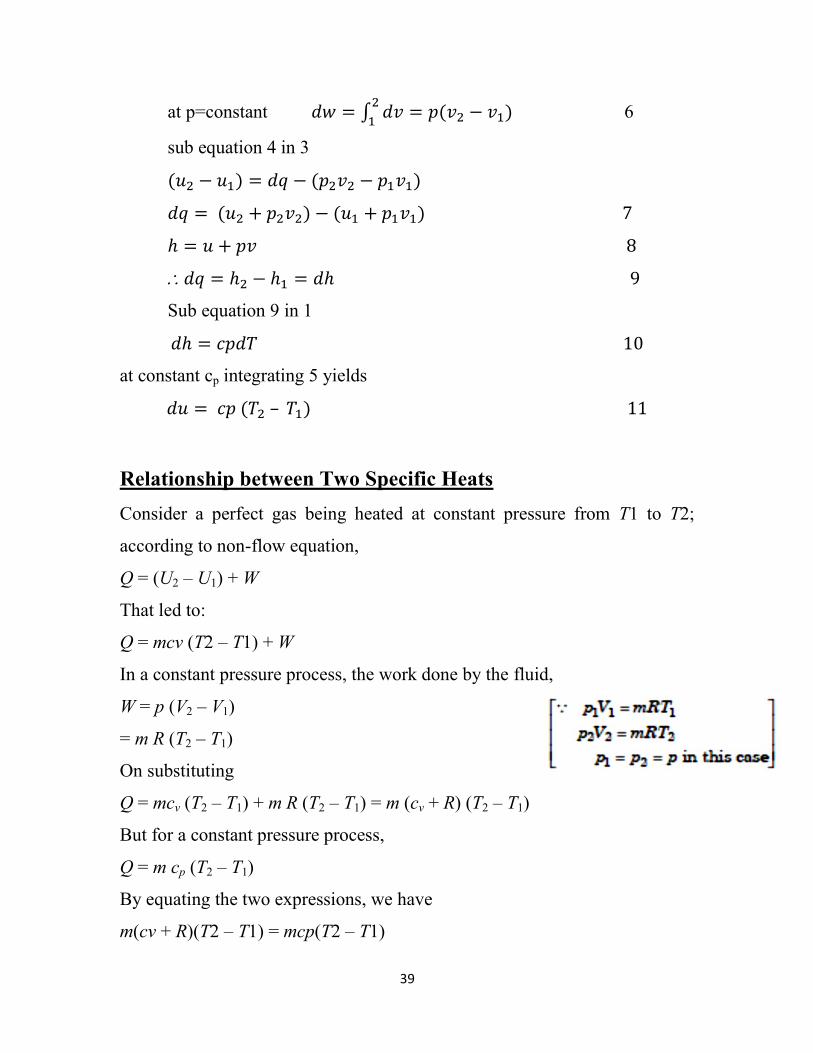
Constant pressure
Using the non-flow energy equation
39
at p=constant
6
sub equation 4 in 3
Sub equation 9 in 1
at constant cp integrating 5 yields
–
Relationship between Two Specific Heats
Consider a perfect gas being heated at constant pressure from T1 to T2;
according to non-flow equation,
Q = (U2 – U1) + W
That led to:
Q = mcv (T2 – T1) + W
In a constant pressure process, the work done by the fluid,
W = p (V2 – V1)
= m R (T2 – T1)
On substituting
Q = mcv (T2 – T1) + m R (T2 – T1) = m (cv + R) (T2 – T1)
But for a constant pressure process,
Q = m cp (T2 – T1)
By equating the two expressions, we have
m(cv + R)(T2 – T1) = mcp(T2 – T1)
41
cv + R = cp
or cp – cv = R
Dividing both sides by cv, we get
Example1 : Figure shows a system comprising of gas in cylinder at pressure
of 689 kPa.
Fluid expands from a volume of 0.04 m3 to 0.045 m3 while pressure remains
constant. Paddle wheel in the system does a work of 4.88 kJ on the system.
Determine (a) work done by system on the piston (b) the net amount of work
done on or by the system.
41
Example2: 0.05 kg of air is heated at constant pressure of 2 bar until the
volume occupied is 0.0658 m3. Calculate the heat supplied and work done,
when the initial temperature is 130 oC . Take cp=1.005kJ/kgK, R=0.287
kJ/kgK.
Example3:
A constant pressure adiabatic system contains 0.13 kg of air at 1.3 bar. The
system receives paddle work. The temperature of the air rises from 29 to 185 oC. Find the total work, mechanical work, change in internal energy and
enthalpy. Take R=0.287 kJ/kgK, specific hears ratio 1.4.
Example 3:
The non-flow energy equation
kJTTmRW
kJQ
KT
KmR
VPT
mRTVP
hhmTTmcQ
TTcRmTTmcTTmRQ
TTmcU
TTmRVVPW
UWQ
p
vv
v
3.7)403912(28.005.0)(
6.25)403912(005.105.0
403273130
912287.005.0
0658.0102
)()(
))(()()(
)(
)()(
12
1
222
2
222
1212
121212
12
1212
P
kJTTmcpH
kJWp
Wp
WpUWQ
kJU
kgKkJcRc
kgKkJR
c
TTmcU
kJW
TTmRVVPWBut
pdVW
adiabaticQ
WpUWQ
vp
v
v
3.20)29185(005.113.0)(
32.20
5.1482.50
5.14)29185(7175.013.0
/005.17175.0287.0
/7175.014.1
287.0
1
)(
82.5)29185(287.013.0
)()(
0
12
12
1212
42
Example4:
A closed constant volume system receives 10kJ of paddle work. The system
contains oxygen at 3.5 bar 45oC and occupied 0.04m3, Find the heat loss or
gain if the final temperature is 185 oC, specific heats ratio is 1.4.
Problems No 3
kJQ
kJU
kgRT
VPm
kgkJR
c
kgKkJR
TTmcU
CVW
WpUWQ
v
O
v
510150
15)45145(649.016945.0
16945.0273452598.0
04.0105.3
/649.014.1
2598.0
1
/2598.032
314.8
)(
0
2
1
11
12
2
43
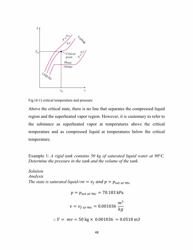
4. Phase Change of Pure Substance
T<100oC Po
Q
1-Sub-cooled liquid
T=100oC Po
Q
2-Saturated liquid
T=100 o
C Po
Q
3-Wet Steam
T=100 o
C Po
Q
4-Saturated Vapour
T>100 o
C Po
Q
5-Super heated Steam
Liquid Vapour Equilibrium :
In figure 1 heat is added at constant pressure Po to the liquid water
at temperature less than 100 oC. as heat is added, the water
temperature rises until it reaches 100 oC, ( figure 2). This
temperature is called as saturated temperature of water at
atmospheric pressure. The amount of heat added is calculated from
the equation:-
).( 12 TTmcHQ w
In figure 3 the water boils and some of liquid is going from saturated
liquid to saturated vapour, the mixture of saturated liquid and
saturated vapour is called wet steam.
TmcwHQ
In figure 4 further transfer of heat to the wet steam will convert the
suspended water droplets into steam and finally a state will be
reached when all water has been turned into steam. The steam is
then called dry saturated steam.
TmcwHQ
In figure 5 Still further transfer of heat to the dry saturated steam
produces a temperature rise and the steam now becomes super
heated steam.
It thus appear that there are three stages in the production of steam:
Stage 1 (process 1-2)
This is the warming phase in which the temperature of water
increases up to saturation temperature. The energy required to
produce this temperature rise is called the liquid enthalpy.
Stage 2 ( process 2-4)
This takes place at constant temperature and is the stage during
which the transformation from water into steam takes place. In this
stage all water saturation temperature at the beginning and all dry
saturated steam at saturation at the end. Between these two
extremes, the steam formed will always be wet steam. The energy
required to produce the total change from all water to all steam is
44
Properties of Steam & liquid
1-Saturation state properties:
1-1 Saturation liquid:
It is the saturation properties of liquid at saturation temperature
corresponding to saturation pressure, the suffix f being used for saturated
liquid properties such as ffff svuh &,, .
1-2Saturation Vapour:
It is the saturation properties of vapour at saturation temperature
corresponding to saturation pressure, the suffix g being used to saturated
steam properties, such as gggg svuh &,, .
2-Wet vapour:
For wet vapour the total enthalpy of the mixture is given by the enthalpy of
saturated liquid present plus the enthalpy of dry saturated vapour present.,
thus for a mass of mt of wet steam contains mg of dry vapour and mf of
saturated liquid, the enthalpy of the mixture can be calculated as:
P T=100oC
Sub-cooled liquid Superheated
. steam
Saturated liquid Saturated vapour
T=100oC
1 2 3 4 5
T=100oC
V
Process from 1 to 5 on the P-V diagram
Latent heat of evaporation: It is the amount of heat absorbed to evaporate I kg of water, at its boiling point, without change of temperature. Process(2-4) Wet steam: The steam that contains
moisture or droplets of water in suspension. Dry saturated steam: The steam of the
substance that does not contains any moisture, and exist at saturated temperature Super heated steam: It us the steam of
the substance at a temperature higher than saturated temperature at a given pressure. Dryness fraction: It is the ratio of the
weight of actual dry steam to the weight of mixture of saturated vapour and saturated liquid( wet steam).
45
fgffgt
fgfft
gtg
t
gt
fgftgtft
g
fgfgft
fg
t
gt
fgftfgt
ffgtffggtt
vxvvhxhxh
uxuuhm
mmh
m
mh
hxhhmmmm
mx
hhhhm
mh
m
mh
hhxhhmmm
xhhhxhhmhmhm
.)1(..
.&.
.,
)(.
).(
..
3-Super heated vapour:
It is the steam of the substance at a temperature higher than saturated
temperature at a given pressure. Compared to saturated vapor, superheated
vapor is characterized by:
Lower pressures (P<Psat. at a given T)
Higher temperatures (T > Tsat. at a given P)
Higher specific volumes (v > vg at a given P or T)
Higher internal energies (u > ug at a given P or T)
Higher enthalpies (h > hg at a given P or T)
Interpolation
For properties which are not tabulated exactly in the tables it is necessary to
interpolate between the values tabulated. For example, to find v, u, h of dry
Saturated steam at 9.8 bar. it is necessary to interpolate between the values
given in the tables. The interpolation assumes a linear variation between the