Oil & Gas Exploration with Electromagnetic Methods
Courses Synopsis: Oil and gas exploration has historically relied on seismic imaging to describe the reservoir and structural setting. High resistivity lithologies such as salt and basalt often define the structural trap of a reservoir, but are difficult to image with seismic data. Lithologies associated with large resistivity contrasts, however, can be detected by electromagnetic techniques such as the magnetotelluric (MT) method. Integrating MT data and seismic data can yield an improved interpretation and reduce exploration risk. The MT method utilizes natural variations in the Earth’s magnetic field as a source. Natural MT signals come from a variety of natural currents including thunderstorms and solar winds as shown in the figure below. The total frequency range of MT data spans 40 kHz to less than 0.0001 Hz. Data is acquired in a passive mode using a combination of electric sensors and induction coil magnetometers that can detect changes in resistivity at great depths. The electric sensors are used to determine the electric field which is derived from measurements of the voltage difference between the electrode pairs Ex
and Ey. The
magnetic coils are used to measure the magnetic fields Hx, Hy and Hz in three orthogonal directions, in this case NS and EW. The ratio of the recorded electric and magnetic values provides an estimate of the apparent resistivity of the Earth at any given depth. The Audio MagnetoTellurics (AMT) method is a subset of the MT sounding technique for audio frequencies ranging between 1 Hz to 20 kHz and higher. It achieves moderate exploration depths to about 2000 m depending on the subsurface resistivity. To date, KMS Technologies has conducted successful MT/AMT surveys in several countries.
KMS Technologies - KJT Enterprises Inc.
An EMGS / RXT company 6420 Richmond Ave., Suite 610
Houston, TX, 77057, USA Tel.: +1.713.532.8144 Fax: +1.832.204.8418
Oil & Gas Exploration with Electromagnetic Methods
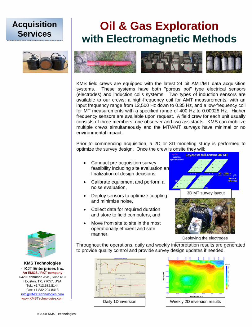
Courses Synopsis:KMS field crews are equipped with the latest 24 bit AMT/MT data acquisition systems. These systems have both "porous pot" type electrical sensors (electrodes) and induction coils systems. Two types of induction sensors are available to our crews: a high-frequency coil for AMT measurements, with an input frequency range from 12,500 Hz down to 0.35 Hz, and a low-frequency coilfor MT measurements with a specified range of 400 Hz to 0.00025 Hz. Higher frequency sensors are available upon request. A field crew for each unit usually consists of three members: one observer and two assistants. KMS can mobilize multiple crews simultaneously and the MT/AMT surveys have minimal or no environmental impact. Prior to commencing acquisition, a 2D or 3D modeling study is performed to optimize the survey design. Once the crew is onsite they will:
• Conduct pre-acquisition survey feasibility including site evaluation and finalization of design decisions,
• Calibrate equipment and perform a noise evaluation,
• Deploy sensors to optimize coupling and minimize noise,
• Collect data for required duration and store to field computers, and
• Move from site to site in the most operationally efficient and safe manner.
Throughout the operations, daily and weekly interpretation results are generated to provide quality control and provide survey design updates if needed. KMS Technologies
- KJT Enterprises Inc. An EMGS / RXT company
6420 Richmond Ave., Suite 610 Houston, TX, 77057, USA
Field data is pre-processed to remove noise and other artifacts that are not signals. The primary objective of this editing is to create a smooth apparent resistivity curve by eliminating from the calculation of each data point any cross powers that were affected by noise. During this process, various hand editing and coherency schemes are employed. Below is an example of data editing. There are two polarization modes utilized for MT surveys: TE mode and TM mode. Generally speaking, the TE mode is consistent with a structural strike, while the TM mode is perpendicular to it. From a resistivity point of view, the distortion of the TM curve is strongly affected by electric lateral inhomogenieties; therefore it can clearly reflect resistivity layering. Determination of the two modes is the first step in interpretation. After the data has been properly edited, it is then Fourier transformed and impedance calculations are generated. The data is then processed through 1D, 2D, and 3D inversion algorithms.
Data editing - unedited data on the left and edited on the right
Integrating MT data with seismic data can add value in complex structural settings as it can be used to update seismic depth imaging. In particular, it can be used to unravel near surface complexities and to define resistive bodies such as salt or basalt. As seen below, MT data can focus seismic imaging (Zerilli, 2002).
Initial seismic image
Resistivity inversion from MT
Updated seismic image to resolve Apula
MT data can be interpreted and analyzed using raw resistivity curves, 2D inversion sections (profiles), resistivity contour maps at different depth levels, and three-dimensional (3D) inversion results. High resolution MT surveys are used to resolve complex imaging problems such salt or subsalt. Final interpretations are to be performed in three dimensions. Results from a high resolution MT survey over a salt body are shown below (Zerilli, 2002).
MT interpretation overlain on seismic Final salt interpretation with feeder stalkCourtesy RWE‐Dea
We offer a complete range of 1D, 2D, and 3D inversion techniques and the ability to integrate MT data with both seismic and other data.
I
Oil & Gas Exploration with Electromagnetic Methods
KMS Technologies - KJT Enterprises Inc.
An EMGS/RXT company 6420 Richmond Ave., Suite 610
Houston, TX, 77057, USA Tel.: +1.713.532.8144 Fax: +1.832.204.8418