Page 1 of 45 OIL INDIA LIMITED (A Government of India Enterprise) P.O. Duliajan, Pin – 786602 Dist-Dibrugarh, Assam CORRIGENDUM Amendment No. 1 Dated 28.10.2015 to Tender No. SDG5523P15/08 This Amendment No. 1 dated 28.10.2015 to Tender No. SDG5523P15/08 for Procurement of Pilot Dehydration Plant is issued to notify certain amendments in the Tender Document. The amendments are given in Annexure-A to this page. All other Terms & Conditions of the Tender Document remain unaltered. (D.Thakur) Chief Manager (Materials)(FD) For Head-Materials
Transcript
Page 1 of 45
OIL INDIA LIMITED
(A Government of India Enterprise) P.O. Duliajan, Pin – 786602
Dist-Dibrugarh, Assam
CORRIGENDUM
Amendment No. 1 Dated 28.10.2015
to Tender No. SDG5523P15/08
This Amendment No. 1 dated 28.10.2015 to Tender No. SDG5523P15/08 for Procurement of Pilot Dehydration Plant is issued to notify certain amendments in the Tender Document. The amendments are given in Annexure-A to this page. All other
Terms & Conditions of the Tender Document remain unaltered.
(D.Thakur) Chief Manager (Materials)(FD)
For Head-Materials
Page 2 of 45
Annexure-A
Existing Description Modified Description Remarks, if any
SECTION – A
2.0 Process Description: 2.1 Objective of the process is to clean up the rated quantity of natural gas and remove moisture and C5+Hydrocarbons (HC). Natural gas at 50 deg C (approx.) and 15 kg/cm2 pressure shall pass through a Coalescence type Filter Separator for removal of any liquid in the flow stream. There are four adsorption beds in the process (two each for water vapor and HC removal). At a time, two (one each for water vapor and HC removal) will run in adsorption mode and the other two will run in desorption mode. The outlet stream of natural gas from the filters will pass successively through adsorption beds for water vapor and HC removal. Once an adsorption bed is saturated, it will be switched over to regeneration mode and there generated bed will be switched into the adsorption mode. 2.2 The dry gas (free of water vapour and heavier HCs) shall be delivered for downstream utilization. A part of the processed dry gas shall be used for high temperature regeneration of the saturated adsorption beds and therefore it will pass through a gas fired gas heater maintained at 300degC. Another part of the stream shall be used as cold regeneration purge stream for the beds during regeneration. 2.3 The wet gas from the beds during regeneration step will be sent into a Gas-Gas heat exchanger as hot stream. The dry gas (cold stream) to be used for regeneration gets preheated. The wet regeneration
2.0 Process Description: Objective of the process is to clean up the rated quantity of natural gas and remove moisture and C5+ Hydrocarbons (HC). Natural gas at 50°C (approx.) and 15 kg/cm2 pressure shall pass through a Coalescence type Filter Separator for removal of any liquid in the flow stream. There are eight adsorption beds in the process (two for water vapour and six for HC removal). At a time, four (one for water vapour and three for HC removal) will run in adsorption mode and the other four will run in the desorption mode. The outlet stream of natural gas from the filters will pass successively through adsorption beds for water vapour and HC removal. Once adsorption beds are saturated, they will be switched over to the regeneration mode and the regenerated beds will be switched into the adsorption mode. The dry gas (free of water vapour and heavier HCs) shall be delivered for downstream utilization. A part of the processed dry gas shall be used for high temperature regeneration of the saturated adsorption beds. In addition, if the required flow of hot regenerated gas is large, some raw feed gas may also be mixed with this stream before sending it through the electric heater. The electric heater shall heat this desired amount of gas for regeneration up to a temperature of about 300°C. The hot gas from the heater is then sent to the beds for regeneration at low pressure (~ 2-3 kg/cm2). This
Point nos. 2.1, 2.2, 2.3, 2.4 & 2.5 are removed and clubbed together. The changes incorporated are marked in red italics as per annexure I (attached).
Page 3 of 45
gas from this exchanger will be delivered to nearby oil processing station. 2.4 Details of the process along with the process
sketch is attached as Annexure –I (3 pages)
2.5 It may be noted here that IIT, Guwahati is the consultant for the said Project and will be associated with OIL for the whole project including installation & Commissioning till testing of the complete pilot plant project in cycle.
3.0Scope of Work:
This is a TURN KEY PROJECT. The scope of work covers the following; i) Mechanical design, Fabrication and Supply of adsorption columns, all process piping, and gas fired gas heater, filter separator. ii) Procurement and supply of all bought out items like valves, control valves, instruments, control panel(s), adsorbents and any other items to meet the process requirement. iii) Cleaning, painting, testing, insulating the process equipment wherever required iv) Assembling all equipment and instrument on suitable skid(s). v) Erection, Testing and Commissioning of the pilot plant at the OIL’s designated site. Vendor shall also be responsible for ensuring inspection of the equipment at the vendor’s works by OIL’s representative and also testing of any equipment at their works if required. Vendor shall also be responsible for pre-commissioning and commissioning activities to be performed at the site to the OIL’s full satisfaction. This specification is not to be interpreted as limiting whereby the vendor is relieved of meeting the requirements specified herein.
stream laden with high content of moisture and/or heavy HC at the outlet of the beds,will be delivered to a nearby oil processing station. A process flow diagram (PFD) of the pilot plant is shown in Annexure II. More elaborate description of process, required instrumentation and hardware is given in the Annexures III and IV. It may be noted here that IIT Guwahati is the consultant for the said Project and will be associated with OIL for the whole project including installation & Commissioning till testing of the complete pilot plant project in cycle. 4.0 Scope of Work This is a TURN KEY PROJECT. The scope of work includes but not limited to the following: 4.1 Development of P&ID, detailed
engineering design of all the hardware and
software including PLC, for the pilot plant.
4.2 Vendor will submit all the detailed design,
P&ID, other drawings, control logic, etc. of the
pilot plant to OIL before starting of construction
of the pilot plant.
4.3 The land footprint with height clearance,
power requirement and water supply requirement
should be clearly spelt out by the vendor and
needs to adhere to the facilities available at the
OIL site. Finalization of the engineering design
and P&ID diagram, etc. will be based on mutual
agreement between OIL and the vendor.
Construction of the pilot plant and procurement
of bought out items shall only be started after
final clearance from OIL.
4.4 Procurement and supply of all bought out
“Scope of work” point 3.0 is removed from the Tender Document and incorporated in point no. 4.0 as per annexure I (attached). The changes are marked in red and in italics.
Page 4 of 45
The vendor shall be responsible for the pilot plant to be completed with all equipment, controls and instrumentation necessary to make the unit a self-contained one for smooth and safe operation. Sufficient descriptive information including a proposed skid layout must be furnished with the Vendors quotation to enable equipment size, performance, quality, and capacity and specification adherence to be determined. It is also necessary that the bidders should furnish complete information / data of the requirement in order to avoid seeking any clarification. The finalization of the engineering design and P&ID diagram will be based on mutual agreement between OIL and the vendor.
items like valves, control valves, instruments,
control panel(s), packing material and any other
items required for fabrication of the pilot plant.
4.5 Fabrication and assembling all
components (hardware & software) to make the
pilot plant
4.6 Cleaning, painting, and insulating the
process equipment wherever required.
4.7 Transportation of all components of the
pilot plant to OIL. The vendor will make necessary
insurance coverage during transportation of the
pilot plant and its components to OIL.
4.8 Erection and commissioning of the unit at
the designated site in OIL.
4.9 The vendor shall be responsible for the
testing facility to be completed with all
equipment, controls, instrumentation, software
necessary to make the unit a self-contained one
for smooth and safe operation.
4.10 Vendor shall also be responsible for
commissioning activities to be performed at OIL
to the full satisfaction of OIL.
4.11 The vendor will also ensure post-
commissioning training to OIL
personnel/representatives on the operation of the
pilot plant.
This specification is not to be interpreted as limiting whereby the vendor is relieved of meeting the requirements specified herein.
4.0 Design Information: 3.0 Process Design Basis
Page 5 of 45
4.1 Process Design Basis: 4.1.1. Feed Condition:
1) Feed Gas Flow Rate (Capacity) : 10,000 SCMD (0.115 m3/sec) 2) Inlet Pressure (Maximum) : 15.0kg/cm2 3) Inlet Gas Temperature : 500C 4) InletGas composition (Vol.%) : an approximate range of gas composition as indicated below – Methane : 83.70 Ethane : 6.80 Propane : 4.50 i-Butane : 1.00 n-Butane : 1.30 Pentane : 0.80 Hexane plus : 0.70 Nitrogen : 0.20 Carbon dioxide : 1.00 Moisture : 5000 ppm Total : 100.00 4.1.2 Climatic Conditions: Maximum shed temperature :45Deg.C. Minimum shed temperature :6 Deg.C. Relative humidity :at 21 Deg.C. = 100% at 32 Deg.C. = 95% at 41 Deg.C. = 70% Height above sea level:Duliajan 119 m (392 ft.) Average rainfall :300 cm. Minimum Ambient temperature:5 Deg.C.
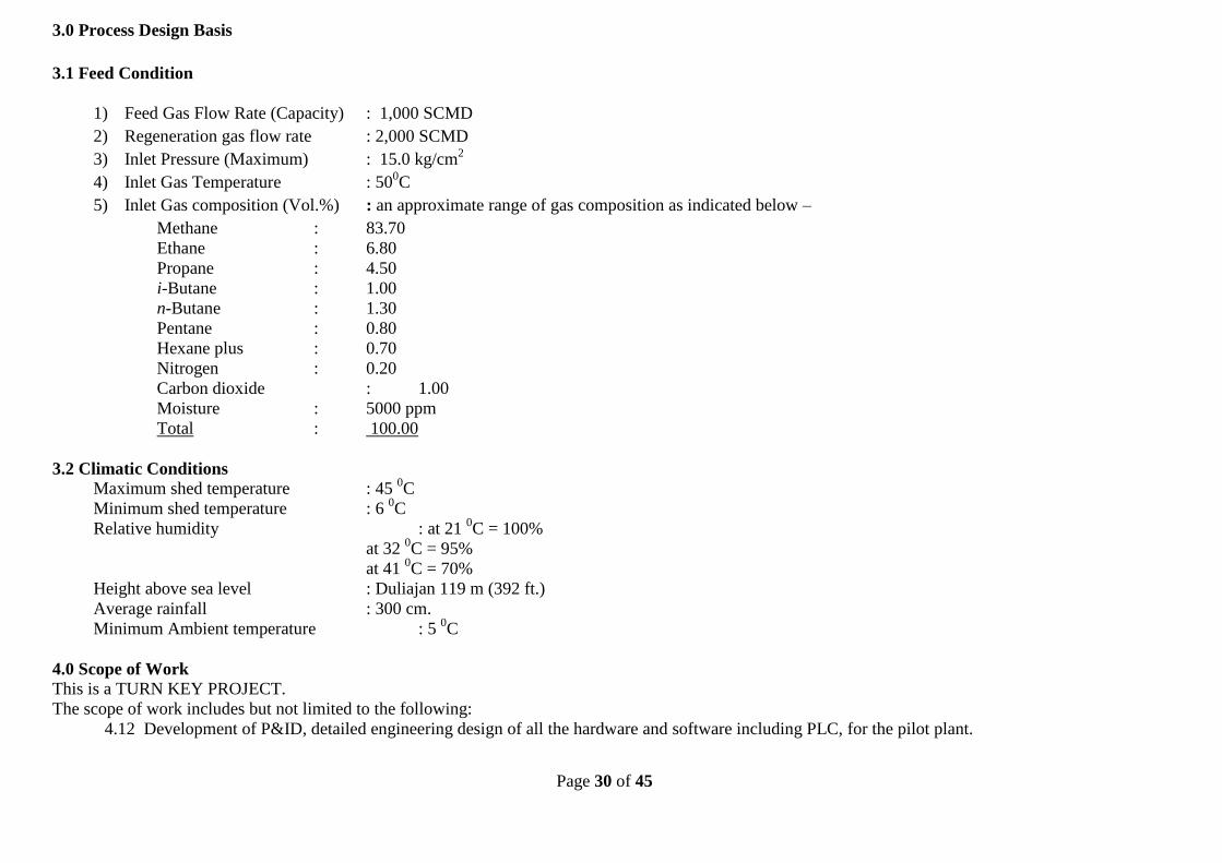
3.1 Feed Condition
1) Feed Gas Flow Rate (Capacity) : 1,000 SCMD
2) Regeneration gas flow rate : 2,000 SCMD
3) Inlet Pressure (Maximum) : 15.0 kg/cm2 4) Inlet Gas Temperature : 500C
5) Inlet Gas composition (Vol.%) : an
approximate range of gas composition as
indicated below –
Methane : 83.70 Ethane : 6.80 Propane : 4.50 i-Butane : 1.00 n-Butane : 1.30 Pentane : 0.80 Hexane plus : 0.70 Nitrogen : 0.20 Carbon dioxide : 1.00 Moisture : 5000 ppm Total : 100.00 3.2 Climatic Conditions Maximum shed temperature : 450C Minimum shed temperature : 6 0C Relative humidity : at 21 0C = 100% at 32 0C = 95% at 41 0C = 70% Height above sea level : Duliajan 119 m (392 ft.) Average rainfall :300 cm. Minimum Ambient temperature:5 0C
Design information stated in Point no. 4.0 is removed and incorporated at point no. 3.0 of annexure I (attached). Feed Gas flow rate changed from 10,000 to 1000 SCMD as shown in red in italics.
Page 6 of 45
5.0 Adsorption Column & Adsorbent
Item 1 &2 columns
for Water (as
per annexure
I)
3&4
columns for
Heavier
Hydrocarbon
(as per
annexure I)
Approx.
Height ,m
1.4 4.75
Approx.
Diameter, m
0.47 1.58
Approx no.
of columns
2 2
Adsorption
time , hrs
12 12
Regeneration
Temp DegC
300 300
Adsorption
Inventory,
Tons
0.34 10.3
* Mechanical design pressure of all the vessels shall be 20 kg/cm2
Elaborately incorporated in Annexure III (Detailed Process Description and Hardware Requirements)(attached) at point no.24.
Point no. 5.0 has been removed and incorporated at annexure III(attached). Height , Bed Dia , Adsorption inventory has been changed.
6.0 Extent of Supply: 6.01 The Pilot Plant will consist of the following: (i) Filter Separator ( Picco Coalescence Filter) : 01 No. – To arrest liquid particles in the flow stream Working pressure : 15 kg/cm2 Working Temperature : 50 Deg. C Filter efficiency : up to 05 micron (i) Adsorption column : 02 Nos. for C5+Hydrocarbon adsorption
Incorporated in Annexure III (Detailed Process Description and Hardware Requirements)(attached) at point no.1,2,3,5,6,7,8,9,10,11,12,13 & 14.
Incorporated in Annexure III (Detailed Process Description and Hardware Requirements)(attached) at point no.1,2,3,5,6,7,8,9,10,11,12,13 & 14.
Page 7 of 45
(ii) Adsorption column :02 Nos. for water vapour adsorption.
All the above adsorption columns (ii) & (iii) shall be complete with necessary instrument, controls for automatic switching of adsorption and regeneration(desorption) cycles as given in Annexure I. Valves and timers are needed for switch over of streams between adsorption and regeneration beds as described in the process. (iii) Gas Fired Heater : 01 No. – For heating the lean gas for regeneration of the adsorbents. Heater for regeneration of the adsorbent media: 30% (max) of the dry process gas (3000 SCMD) will be used at a temperature of 300Deg C. Forced draft gas fired burner with burner management system having automatic on-off main burner to be provided. Pilot burner shall have flame failure shutdown switch. Pilot gas and main burner gas will be supplied to the burners from the residue gas line and each must have its own regulator and shut down valve. Details of burner instrumentation to be provided are given in instrumentation section (Section 8.0). (iv) Gas – Gas Heat Exchanger: 01 No. - To cool down the warm outlet wet gas after regenerating the adsorbents and to preheat the dry regeneration / fuel gas. The heat exchange will take place between regenerated wet gas and the dry regeneration / fuel gas. (v) Pressure Control Valve with pressure controller: 01 No. - Up-stream control valve will be used for transferring process lean gas to Low Pressure system.
Page 8 of 45
(vi) Check valve : 1 No. - To ensure one way flow of regeneration wet gas into LP unit (vii) Flow control valve with flow controller: 6 Nos. (S1, S5, S7, S8, S10 and S11 – Refer Annexure -I) (viii) The bidder to submit the following along with the bid: a) Submission of technical specifications of all equipment to be used and supplied. b) Submission of P&ID, different flow circuits, pressure/temperature control circuits etc. c) Submission of General Arrangement Drawing (GAD) (ix) Bidder to give an undertaking that detailed Mechanical/ Engineering Design with Engineering drawing including internals of all equipment shall be submitted if the order is placed on them.
Page 9 of 45
7.0 Adsorbents: Adsorbent Type-1 : Molecular Sieve 4A, 1/16’’ pellets Adsorbent Type-2 : Silica Gel beads 2‐5 mm The physical properties of the adsorbents to be supplied are as follows. (a) Molecular sieve 4A a. Size: 1/16” pellets or 2-4 mm spherical beads b. Water adsorption capacity: 20 wt % minimum at 18 mm Hg and 25 deg C (b) Silica gel: a. Size: 2-5 mm spherical beads b. Pure methane (CH4) capacity: not more than 11 cc at STP/gm of silica gel at partial pressure of 9 bar and 20 deg C and not more than 6 cc at STP/gm of silica gel at partial pressure of 93 bar and 75 deg C. c. Pure n-pentane (C5H12) capacity: At least 40 cc at STP/gm of silica gel at partial pressure of 0.3 bar and 20 deg C and at least 6.5 cc at STP/gm of silica gel at partial pressure of 0.3 bar and 75 deg C. d. BET Surface area: Minimum 550 m2/g (c) The adsorbents should be procured from reputed vendors such as Linde, UOP,M/s Chemicals India Company,M/s Drier Chemicals etc. The samples should be validated to OIL before actual purchase by the vendor. ** All the adsorption columns / equipment will be exposed to around 300 deg C, all equipment /vessels instrument andmaterials shall be selected accordingly.
Incorporated in Annexure III (Detailed Process Description and Hardware Requirements) (attached) at point no. 4
Incorporated in Annexure III (Detailed Process Description and Hardware Requirements)(attached) at point no. 4
Page 10 of 45
8.0 Instrumentation System:
Project Requirement:
The instrumentation& control system requirement pertaining to this pilot project is envisaged as per the following. However, the final quantity/specific range/exact requirement will depend on the final approval of the ‘design of the pilot plant’ by the qualified bidder.
Monitoring & Control of Gas Fired Heater - Burner Management System(BMS) for sequence of operation like Blower(purging) Motor on/off, pilot ignition, main burner on/off, safety shutdown, alarm etc. through a dedicated Small Programmable Logic Controller considering forced draft heater. - A dedicated temperature control function for maintaining the regeneration gas temperature between 130 - 300 deg C through Small Programmable Logic Controller and thereby controlling main burner fuel intake to the heater. - Temperature transmitter(s) - Temperature Gauge for local indication - Heater stack temperature transmitter for indication & safety shutdown - Fuel Gas Pressure Transmitter - A dedicated control panel for burner on/off, pilot & main flame status, fuel valves status, emergency manual shutdown, temperature & pressure indications, indicating Lamp etc. The panel will house the Small Programmable Logic Controller(SPLC) along with all standard accessories in the control panel as per standard engineering practice
Monitoring & Control of Adsorption Columns - Automatic changeover of columns from adsorption to regeneration & vice versa after
5.0 Instrumentation The instrumentation and control system requirement pertaining to this pilot project is envisaged as per the following in addition to the instrumentation and hardware included in Annexure III. However, the final quantity/specific range/exact requirement will depend on the mutually agreed version of the P&ID as indicated in the Scope of Work. 5.1 Provision for automatic emergency safety
shutdown along with suitable ON/OFF valves.
5.2 All the instrumentation (for
measurement/control of temperature,
pressure, flow, etc.) will include independent
display units at a suitable central location.
5.3 All field instruments shall be hooked up with
the PLC control panel for necessary display&
monitoring, start/stop actions, control etc.
5.4 All materials used are to be provided with
test certificates.
5.5 The instrumentation work shall include
design, engineering, calibration, testing,
installation, supply, erection and
commissioning of field instruments, local
control panel(s) and instrumentation cable
with all accessories, cable trays, junction
boxes, erection hardware etc. as per
requirements.
5.6 The following selected one or all
instrumentation works are envisaged as
Point no. 8.0 has been removed and incorporated at point no. 5.0 of the revised specification of annexure I (attached). The Instrumentation is elaborated Incorporated in point no. 5.0 of Annexure I (attached). Changed to suit the new process requirement.
Page 11 of 45
completion of definite time cycle operation, sequence of operation of control valves either in ON or OFF mode in the inlet & outlet sections of the respective columns through a dedicated Programmable Logic Controller (PLC). Provision for automatic emergency safety shutdown, manual step-up & step-down of time cycle operation of adsorption columns & manual changeover of adsorption column whenever process condition demands. - Pressure Transmitter(s) for adsorption columns(Total 8 nos. one each at the top and bottom for beds 1, 2,3&4). - RTDwith thermowell for adsorption columnsone each at the top and bottom for beds 1, 2,3, and 4.(Total = 8 nos.) - RTD with thermowell for Streams S1 (after filter separator), S5 (before entering the heat exchanger), S18 (before entering the heat exchanger) and S9 (at the outlet of the heater). (Total = 4 nos.) - RTD with thermowellat the following locations in beds 1 and 2. (Total = 4 nos.) a) 0.01 m from wall at a height of 0.7 m b) 0.22 m from wall at a height of 0.7 m - RTD with thermowellat the following locations in beds 3 and 4. (Total = 14 nos.) a) 0.01 m from wall at a height of 2.4 m b) 0.35 m from wall at a height of 2.4 m c) 0.70 m from wall at a height of 2.4 m d) 0.01 m from wall at a height of 0.8 m e) 0.01 m from wall at a height of 1.6 m f) 0.01 m from wall at a height of 3.2 m g) 0.01 m from wall at a height of 4.0 m - Temperature transmitters for all the above RTDs - Pressure & temperature switches for each columns for safety shutdown - Pressure & temperature gauges for each columns for local indication
minimum but shall not be limited to:
5.6.1 Engineering, supply, erection, testing and
commissioning of field instruments,
Burner Management System,
instrumentation cables, junction boxes,
serial link cable for PLC, Control Panels
etc.
5.6.2 Cable lying through cable tray/cable
trench from Gas Fired Heater/ Adsorption
Columns/Gas-Gas Heat Exchanger to control
panels via junction boxes with proper glanding,
termination, ferruling, dressing etc.
5.6.3 Installation of junction boxes, I/O
cabinets in the control panels.
5.6.4 Calibration of all instruments, leak
test/hydro test of instrument impulse pipe,
tubes, fittings etc.
5.6.5 To interface all instrumentation signals
with the Programmable Logic Controller (PLC) in
the control panel.
5.6.6 Supply of erection hardware’s like cable
gland, cable trays, support, SS tubing, fittings,
flanges, valves, manifold, impulse tubing etc.
5.6.7 Supply of mandatory recommended
spares for smooth running of the pilot plant after
Post Commissioning Warranty.
5.6.8 Preparation of engineering
drawing/documents/data sheet/P&ID etc.
5.6.9 Erection, testing & commissioning of ON-
OFF control valves at the inlet & outlet of
Page 12 of 45
- Limit switches/LVDT for columns inlet & outlet valves status like ON/OFF and opening/closing position& sequence interlock and safety shutdown. - ON/OFF control valves - A dedicated main control panel for the adsorption columns which will comprises of Master Programmable Logic Controller, critical parameters display along with indicating lamps, start/stop & sequence of columns operation after getting required feedback signal (safety interlock) from the Small Logic Controller in Gas Fired Heater & vice versa, all standard accessories in the control panel as per standard engineering practice. - Solenoid valves. All solenoid valves to be housed in a separate enclosure with proper air supply regulator & filters assembly and to be placed near the near the main control panel for interlinking. - Tapping ports to withdraw sample for concentration analysis in each of the streams S1, S2, S4, S9, S13, S14, S15, S16 and S18 - Pressure gauges at suitable locations in the pipeline as per standard engineering practice.
Monitoring & Control of Filter Separator - Differential Pressure(DP) Gauge - Local pressure gauges for Inlet & Outlet of Filter Separator - Pressure transmitter in the filter separator outlet. The pressure transmitter signal to be feed to the Main Programmable Logic Controller for controlling columns operation based on the minimum & maximum permissible pressure limit as per design basis.
Gas-Gas Heat Exchanger - Local Pressure & Temperature gauges Control valve with positioner & I/P converter and pressure controller action (PID) from Main
Adsorption columns.
5.6.10 Necessary control logic shall be
developed in the Programmable Logic Controller
(PLC) for smooth operation & safety shutdown of
the pilot plant as well as display of critical
parameters in the control panel(s) along with
indicating lamp.
5.6.11 Interconnecting Gas Heater Control Panel
and main Control Panel of Adsorption Unit for
safety interlock.
5.6.12 The system is to be provided complete
with all instrumentation and valves for automatic
operation and shutdown at all stages of the
system. All pressure vessels are to be fitted with
pressure safety valves.
5.6.13 All control valves and metering systems
are to be provided with manually operated by-
pass arrangements. All instruments should be
provided with suitable isolation valves on both
sides to enable proper maintenance.
Page 13 of 45
Programmable Controller (PLC) for Process Lean Gas to LP System.
Gas Flow Measurement & Flow Control - Gas Flow Measurement & flow control in the stream S4, S5, S7, S8, S10 & S11 - Gas flow measurement with Multivariable Transmitter along with orifice plate as per AGA-3. - All the above Gas Flow Calculation to be done in PLC with necessary programming software meeting requirement as per AGA-3. - PLC’s must be compatible for gas flow allocution with sufficient memory (RAM) and display must be in the TFT display monitor. - Control valve(s) with positioned & I/P converter and flow control action(PD or PID) from main Programmable Logic Controller(PLC).
APPLICABLE CODES & STANDARDS
The following Indian and International codes and standards are generally used for design of Instrumentation works. In all cases, latest revisions with amendments if any shall be followed. Apart from the specific codes mentioned herein, all other relevant and related codes concerning the specific job under consideration and/or referred to in these codes and technical specifications are followed wherever applicable.
a) ANSI/ISA S51.1 - Process Instrumentation Terminology.
b) IEC 60529 - Classification of Degree of protection provided by Enclosures
c) IEC 60079- Specification for Flame Proof Enclosure
Page 14 of 45
d) IEC 801 - Electromagnetic Compatibility for Industrial Process Measurement And control equipment
e) IEC 902 - Industrial Process Measurement and Control terms and definitions.
f) IEC 228- Conductors of insulated cables.
g) IEC 5381- Specification for PVC insulation and sheath of insulated cables.
h) API RP 520- Sizing and selection of safety relief valves.
i) IS 1554 Part 1- PVC insulated (heavy duty) electric cables- working voltage upto And including 1100 V.
j) IS 3975 -Mild steel wires, formed wires and tapes for armoring of cables.
k) IS2147 - Degree of protection provided by Enclosures for low voltage Switchgears and control gears
l) IS 2146 - Flame proof Enclosures of Electrical Apparatus
m) BS EN 50054-Electrical Apparatus for the Detection and Measurement of
Combustible Gas-General Requirements and Test methods.
n) BS EN 50057 - Performance Requirements for Group II Apparatus Indicating up to 100% LEL
o) BS 5308 Part 2 -Specification for PVC insulated cables.
p) ISA S75.01-Control Valve Sizing
Design Basis (Instrumentation):
i) Field Transmitters should be intrinsically safe
Page 15 of 45
under leak proof enclosure for use in hazardous area. Function of the transmitter shall be transmission as well as indication. Type of transmitter shall be of electronic smart type transmitter compatible with fieldbus protocol of latest version with capability to handshake with any communicating device. The enclosure should be weather proof to IP 65.
ii) RTD will be 4-wire duplex and thermo well’s immersion length shall be suitable for the line size. RTD element shall be Pt 100 and it will be as per DIN 43760 and accuracy will be class A.
iii) For Gas Flow Application (flow measurement) multivariable transmitter along with orifice plate shall be used. Multivariable transmitter shall be of electronic smart type transmitter compatible with fieldbus protocol of latest version with capability to handshake with any communicating device. This transmitter shall have RTD connectivity also for flow calculation as well as transmitting temperature to PLC. Accuracy of this transmitter should not be degraded beyond±0.15%.
iv) All field instruments shall be hooked up with the respective PLC control panel for necessary start/stop, display& monitoring, sequence interlock & safety shutdown, gas flow calculation as per AGA-3. All control logic for sequence of operation and safety shutdown of the unit to be developed accordingly.
v) A high resolution(1024 x 768, 18-bit color graphics) TFT display monitor unit with touch screen/ key board for monitoring of all parameters like Pressure, Temperature, Flow, Valves status(ON/OFF) etc. including alarm & graphical display shall be considered in PLC control panel. This LCD display unit shall be hooked up with the PLC through suitable communication protocol (Ethernet, RS 232, RS 485 etc.).
Page 16 of 45
vi) A standalone Burner Management System(BMS) along with requisite accessories or through PLC including IR flame detector, Ignition transformer with electrode, damper control, pilot & main burner regulator with control etc. shall be considered.
vii) Based on the ‘schematic flow diagram’, shall have to design complete logic & sequence control operation and safety shutdown and assessment of total requirement of field & control instrumentation system for the entire dehydration unit. Scope of Work (Instrumentation): i) The instrumentation work for the pilot project shall include design, engineering, supply, installation, calibration, testing, erection and commissioning of field instruments, local control panel(s) and instrumentation cable with all accessories, cable trays, junction boxes, erection hardwires etc as per requirements. ii) The following selected ones or all instrumentation works are envisaged in this pilot project as minimum but shall not be limited to: a) Engineering, supply, erection, testing and commissioning of field instruments, Burner Management System, instrumentation cables, junction boxes, serial link cable for PLC, Control Panels etc. b) Cable lying through cable tray/cable trench from Gas Fired Heater/ Adsorption Columns/Gas-Gas Heat Exchanger to control panels via junction boxes with proper glanding, termination, ferruling, dressing etc. c) Installation of junction boxes, I/O cabinets in the control panels. d) Calibration of all instruments, leak test/hydro
Page 17 of 45
test of instrument impulse pipe, tubes, fittings etc. e) To interface all instrumentation signals with the Programmable Logic Controller (PLC) in the control panel. f) Supply of erection hardware’s like cable gland, cable trays, support, SS tubing, fittings, flanges, valves, manifold, impulse tubing etc. g) Supply of mandatory recommended spares for smooth running of the pilot plant after Post Commissioning Warranty. h) Preparation of engineering drawing/documents/data sheet/P&ID etc. i) Erection, testing & commissioning of ON-OFF control valves at the inlet & outlet of Adsorption columns. j) Necessary control logic shall be developed in the Programmable Logic Controller (PLC) for smooth operation & safety shutdown of the pilot plant as well as display of critical parameters in the control panel(s) along with indicating lamp. k) Interconnecting Gas Heater Control Panel and main Control Panel of Adsorption Unit for safety interlock. iii) The system is to be provided complete with all instrumentation and valves for automatic operation and shutdown at all stages of the system. All pressure vessels are to be fitted with pressure safety valves. iv) All control valves and metering systems are to be provided with manually operated by-pass arrangements. All instruments should be provided with suitable isolation valves on both sides to enable proper maintenance.
Page 18 of 45
Special Condition:
i) All field mounted instruments (hazardous area) shall be ‘Intrinsically Safe’ under leak proof enclosure. ii) All signals from field instruments in hazardous area shall be routed through suitable Zener barrier/isolator. iii) All field instruments/control panel installed in Zone 1 are to be certified by CIMFR/ERTL and approved by DGMS as per OIL’s approved safety policy as well as statutory body’s requirement. Hence, the bidder to procure the various field instrumentation system/control panel which are already certified & approved by CIMFR/ERTL& DGMS and used in OIL’s various installations subject to meeting the individual instrumentation design specifications. OIL will provide the list of the certified & approved only availablefield instrument/control panel along with the vendors address after final approval of the ‘Pilot Plant Design’. iv) Main Control Panel of Adsorption Columns Unit to be erected & placed at a distance of 6 to 8 meters from the vessel skid. The panel should be purging type & to maintain a positive pressure of +3 PSI inside the panel. v) For Gas Fired Heater, Instrumentation System & Control Panel does not require CIMFR& DGMS certification as the Heater will be installed in safe area beyond Zone-2 which will be minimum 45 meters away from the process skid. However, all instrumentation system for heater should be intrinsically safe.
6.0 Special Condition:
6.1 All field mounted instruments (hazardous
area) shall be ‘Intrinsically Safe’ under leak proof
enclosure.
6.2 All signals from field instruments in hazardous
area shall be routed through suitable Zener
barrier/isolator.
6.3 All field instruments/control panel installed in
Zone 1 are to be certified by CIMFR/ERTL and
approved by DGMS as per OIL’s approved
safety policy as well as statutory body’s
requirement. Hence, the bidder to procure
the various field instrumentation
system/control panel which are already
certified & approved by CIMFR/ERTL & DGMS
and used in OIL’s various installations subject
to meeting the individual instrumentation
design specifications. OIL will provide the list
of the certified & approved only available
field instrument/control panel along with the
vendors address after final approval of the
‘Pilot Plant Design’.
6.4 Main Control Panel of Adsorption Columns
Unit to be erected & placed at a distance of 6
to 8 meters from the vessel skid. The panel
should be purging type & to maintain a
positive pressure of +3 PSI inside the panel.
6.5 For Gas Fired Heater, Instrumentation
System & Control Panel does not require CIMFR
& DGMS certification as the Heater will be
installed in safe area beyond Zone-2 which will be
Roman i), ii), iii) , iv) & v) has been removed and marked as 6.1,6.2,6.3,6.4 & 6.5 under point no. 6.0 of annexure I.
Page 19 of 45
Note: (i) The payment terms for the field instruments and control panel is as under – (a) The supplied field instruments including the control panel having CIMFRas well as DGMS certification will be paid 100% as per payment terms & conditions of the contract. (b) The field instruments including the control panel supplied without DGMScertification but having field trial approval of DGMS will be paid 50% of the total value of the supplied instruments/ control panel as per the payment terms & conditions of the contract. (ii) The bidder has to provide item wise cost break-up for all field instruments including control panel. Recommended vendor list for the instrumentation system shall be of the following make preferably. Programmable Logic Controller: Allen Bradley/SIEMENS Control Panel : Rittal/Pyrotech/ICA/Altronic/Murphy Control Valves: Fisher / Fouress / Instrumentation Ltd. Transmitters (PR & Temp) : ABB/EMERSON Process/Murphy Pressure Switch:INDFOS/Switzer/Murphy Pressure & Temperature Gauges : Warrey/Bourdon/Precision/Murphy Safety Relief Valve : AIL/Farris. Solenoid Valves : ASCO / Rotex / Schradder Limit Switch/LVDT:Speed-O-Control/Remso Controls/Honeywell IS Barrier/Isolator/Repeater : P&F/MTL Digital Panel Indicator: Masibus/Honeywell/ABB
minimum 45 meters away from the process skid.
However, all instrumentation system for heater
should be intrinsically safe.
6.6 The payment terms for the field
instruments and control panel is as under –
6.6.1 The supplied field instruments including
the control panel having CIMFR as well as DGMS
certification will be paid 100% as per payment
terms & conditions of the contract.
6.6.2 The field instruments including the
control panel supplied without DGMS
certification but having field trial approval of
DGMS will be paid 50% of the total value of the
supplied instruments/ control panel as per the
payment terms & conditions of the contract.
6.6.3 The bidder has to provide item wise cost
break-up for all field instruments including
control panel.
Suggested Vendor list has been incorporated at point no. 22.0 of annexure III (attached).
Note has been removed and all the points covered in the Note are included under special condition at point nos. 6.6 Suggested Vendor list has been incorporated at point no. 22.0 of annexure III(attached).
Page 20 of 45
RTD with Thermowell : Pyrotech Controls/ALTOP/General Inst./Murphy Instrument& Power cable : INCAB/Universal Cable/RPG Cables Instrument Fittings : Swagelok/Parker/IVI vales SS Tube : Sanvik Terminal Block :Phoneix/Elemex/Wago Interposing Relay : OEN/Jyoti/Omron Alarm Annunciator : IIC/Procon/Murphy Air Filter Regulator :Shavonorgren/Placka 24 V DC Power Supply :Phoenix/Silop Indicating Lamp:Concord/Telemechnic/Murphy Cable Gland :Baliga/Electromac Lugs :Dowells Junction Box : Baliga/Flexpro Chemically treated earth pit : Ashlok/Welcome World Engg/Power gomengg MCB (Miniature Circuit Breaker): MDS/HAGER/Wowells Fuse (LT): KAYCEE /GE/ALSTOM Push Button : KAYCEE/Telemechnic/Siemens Selector Switches : KAYCEE/Siemens Control switches : KAYCEE/Siemens Light Fittings (Panel Indoor) : GE/Bajaj/Philips Circuit Breaker (Inside panel) : GE/Siemens/Schneider Ball Valves (for impulse line) : Flow Control/L&T/Flow Chem Globe Valves (for instruments) : L&T/Hawa valves/NECO Valves GeneralSpecifications of the Instrumentation System: As per attached Annexure-II (attached)
Page 21 of 45
9.0 Valves: 9.1 The valves shall be selected as per the process
condition and shall be procured from L&T, Virgo Valves & Controls. For hydrocarbon service, ball valves to be used.
9.2 Valve trim in hydrocarbon service shall be suitable for hydrocarbon with 10% carbon dioxide.
9.3 All valves shall be of fire safe type as per API 1607 / BS 5146. Fire safe test shall be as per the standard and test certificate shall be furnished.
9.4 Body, bonnet, cover etc. of all valves shall be from carbon steel casting or forged steel. Steel casting orforging shall be of radiographic quality as per procedure and acceptance criteria specified in ANSI B 16.34 – 1977.
9.5 All valves shall be with flanged ends as per ANSI B 16.5.
Point no. 9.0 has been Incorporated at point no. 15.0 of Annexure III (attached).
Point no. 9.0 has been Incorporated at point no. 15.0 of Annexure III (attached).
10.0 Pipes and Fittings: 10.1 All piping materials and fabrication shall
conform to ANSI B 31.3 (latest edition). 10.2 All carbon steel fittings shall be as per ASTM A
234 WPB seamless. 10.3 The vendor shall provide and connect all inter-
all drain headers etc. Spool pieces, if required shall be provided to finally connect by the bidder to adjacent skids (if the number of skids is more than one) together at site.
10.4 All connection in piping, valves etc. shall be through weld neck forged carbon steel flanges as per ANSI B 16.5.
10.5 All pipe fittings shall be from carbon steel made through forging. Fabricated fittings such as bends, elbows, tees etc. made through welding are not allowed.
Point no. 10.0 has been removed & Incorporated at point no. 17.0 of Annexure III (attached).
Point no. 10.0 has been Incorporated at point no. 17.0 of Annexure III (attached).
Page 22 of 45
10.6 All welding joints shall be of radiographic quality as per API 1104 and at least 20% of the welding joints shall be radio graphed and radiographic films submitted to OIL.
10.7 Piping shall be arranged in such a manner to avoid crisscrossing or overhead problems. Piping or tubing of insufficient mechanical strength for standing or hanging shall be protected from personnel traffic.
10.8 All sub-suppliers items e.g., instruments, valves, pipes fittings etc. shall be from reputed manufacturer / supplier and should conform to relevant codes and standards.
Note: Since the plant equipment will be exposed
above 250 deg C, all valves /pipes / pipe fitting metallurgy shall be selected accordingly .
11.0 Codes and Standards: The following codes and standards will apply: ASME VIII DIV. 1 Latest Edition ASME Section IX - Do- ANSI B 16.5 - Do- ANSI B 31.3 - Do-
Point no. 11.0 has been removed & Incorporated at point no. 19.0 of Annexure III (attached).
Point no. 11.0 has been removed & Incorporated at point no. 19.0 of Annexure III (attached).
12.0 Skids: 12.1 Each unit like adsorption column, heater, filter etc along with its instruments should be skid mounted. The skids should be fabricated from suitable structural steel section. The skids must be rugged and compact, being designed for transportation by trailer and fitted with two bars. Vendor to provide lifting arrangements for all the skids and minimum number of skid should be employed. Details of bolting down
Point no. 12.0 has been removed and incorporated at point no. 20.0 of annexure III(attached) under heading “Mounting”
Point no. 12.0 has been removed and incorporated at point no. 20.0 of annexure III(attached) under heading “Mounting”
Page 23 of 45
for skids to be provided by vendor.
13.0 Material of Construction: Materials to be used as follows: Vessels / Tanks:SA-515 Gr. 60 / 70 / IS:2002 Gr. 2 Shell flanges : SA-105 Nozzle flanges : SA-105 Supports : SA-283 Gr. C/IS:226 Nuts & Bolts : SA 193 Gr. B7
SA 194 Gr. 2H Materials for pipes, flanges, fittings to be in
accordance with ANSI B31.3 / API 51 / ANSI B16.5. Material for instrument piping to be annealed
seamless 316 stainless steel with Swagelok type fittings.
Point no. 13.0 has been removed and incorporated at point no. 18.0 of annexure III(attached).
Point no. 13.0 has been removed and incorporated at point no. 18.0 of annexure III(attached).
14.0 Available Utilities:
14.1 Electrical Power Supply: Rated voltage : 240 V-AC (± 10%), 3 phase
Rated frequency : 50 Hz (± 3%) Control voltage : 240V, 1 phase
15.0 Inspection: Vendor to provide a schedule of onsite inspection for the manufacturing stages including bought-out items of instrumentation and controls with the tender at Vendor’s Works. All materials to be used in the process of manufacturing are to be provided with test certificates. OIL‘s personnel may visit at any stages of execution of the job for which necessary facility and co-operation will have to be extended by the vendor and minimum 15 days prior intimation is required for schedule inspections.
Point no. 15.0 has been removed and incorporated at point no. 7.0 of annexure I(attached).
Point no. 15.0 has been removed and incorporated at point no. 7.0 of annexure I(attached).
16.0 Painting & Insulation: The equipment and skids are to be externally painted for environmental protection after thorough cleaning. As a minimum, this is to include zinc rich primer (1 coat) and epoxy based final covering. Vendor to provide the proposed specification with his tender. Cleaning shall be done through sand blasting before painting with spray. The heater delivery line (hot surfaces) shall be properly insulated with and then covered with aluminum sheet jacket.
Point no. 15.0 has been removed and incorporated at point no. 9.0 of annexure I(attached).
Point no. 15.0 has been removed and incorporated at point no. 9.0 of annexure I(attached).
Page 25 of 45
17.0 Guarantee: 17.1 Vendor to stand guarantee for a period of 6 months from the date of successful commissioning of the plant for any type of mechanical, instrumentation design failures including performance of the equipment and instruments at specified conditions. 17.2 Guarantee period will start from the date the plant operates satisfactorily as per design parameters and ordered specifications.
Point no. 17.0 has been removed and incorporated at point no. 10.0 of annexure I(attached).
18.0 Spares and Adsorbents: Spares and adsorbents wherever required for successful testing, commissioning and operation of the unit after erection at sites in all respect must be supplied by the vendor at their own cost.
Point no. 18.0 has been removed and incorporated at point no. 12.0 of annexure I(attached).
Point no. 18.0 has been removed and incorporated at point no. 12.0 of annexure I(attached).
19.0 Testing and Commissioning: 19.1 The vendor will be responsible for testing and commissioning of the unit at site. The commissioning period will be for 3 days (72 hours) and will be counted from the time when the plant becomes normal and operates as per design / ordered parameters. If the plant requires to be shut down before completion of 03 days operation period due to malfunctioning of equipment, instruments etc. supplied by the vendor, 03 days operation period will be counted afresh. Only after continuous operation of the unit for a period of 3 days (72 hours), it will be considered as commissioned successfully. 19.2 If any malfunction, abnormality occurs during trial/commissioning period, the party to rectify the same at their own expense.
8.0 Testing and Commissioning
8.1 The vendor will be responsible for testing and
commissioning of the unit at site. The
commissioning period will be for 3 days (72
hours) and will be counted from the time when
the plant becomes normal and operates as per
design / ordered parameters. If the plant
requires to be shut down before completion of
03 days operation period due to malfunctioning
of equipment, instruments etc. supplied by the
vendor, 03 days operation period will be counted
afresh. Only after continuous operation of the
unit for a period of 3 days (72 hours), it will be
considered as commissioned successfully.
8.2 If any malfunction, abnormality occurs during
trial/commissioning period, the party to rectify
Point no. 19.0 has been removed and incorporated at point no. 8.0 of annexure I(attached).
Page 26 of 45
the same at their own expense.
20.0 Operation and maintenance: 20.1 The pilot plant is expected to operate for 3 (three) months (90 days) continuously for establishing the process parameters and operating principle for a scaled up plant. The vendor shall have to provide round the clock operation and maintenance of the plant during this period. Accommodation and transportation for the vendor’s staff during this period shall be arranged by the vendor. OIL may provide accommodation on chargeable basis. 20.2 Charges for operation and maintenance shall be quoted separately on per month basis.
Point no. 20.0 has been removed and incorporated at point no. 11.0 of annexure I(attached).
Point no. 20.0 has been removed and incorporated at point no. 11.0 of annexure I(attached).
21.0 Exception and Deviation: Vendor should mention separately, in clear terms the deviations and exclusions in his offer from the tender specification.
Point no. 21.0 has been removed and incorporated at point no. 13.0 of annexure I(attached).
Point no. 21.0 has been removed and incorporated at point no. 13.0 of annexure I(attached).
22.0 Delivery Schedule: Bidders are to give their best realistic delivery schedule.
Point no. 22.0 has been removed and incorporated at point no. 14.0 of annexure I(attached).
Point no. 22.0 has been removed and incorporated at point no. 14.0 of annexure I(attached).
15.0 Bidding details:
The bidders should also include the following in their bid documents 15.1 An undertaking that detailed Mechanical/
Engineering Design with P&ID drawing along
with electrical/PLC and structural layout will be
submitted if the order is placed on them.
15.2 At least 12 months warranty for the test
facility along with all its components will be
provided.
15.3 Complete information / data in order to
Point no. 15.0 of annexure I (attached) has been newly incorporated.
Page 27 of 45
avoid seeking any clarification on the bid
documents.
15.4 Material Supply: Cost of the materials
along with transportation charge, taxes and
insurance, if any. The optional items indicated
should be quoted separately item wise.
15.5 Erection & Commissioning: Cost of
erection and commissioning of the plant at OIL
site.
15.6 In the price bid, bidders to quote the
following:
15.6.1 Material Supply (Lump Sum): Cost of the
materials alongwith transportation charge, taxes
and insurance, if any.
15.6.2 Erection & Commissioning at site (Lump
Sum) : Erection and commissioning of the plant.
15.6.3 Operation & Maintenance (Per Month):
Operation and Maintenance cost of the plant
15.7 After the placement of the order to the successful bidder, the party will be asked to: 15.7.1 Submit a detailed drawing and technical specification of all equipment of the test facility to OIL before fabrication for approval. P&ID, different flow circuits, pressure/temperature control circuits etc. should also be included in this document. 15.7.2 Arrange for pre-delivery inspection 15.7.3 Ensure post-commissioning training to the OIL personnel for operation of the pilot plant.
Point no. 16 & 23 are newly incorporated at annexure III (attached) and it should be part of the tender document.
Point no. 16 & 23 are newly incorporated. Shown in annexure III (attached) and it should be part of the tender document.
Page 28 of 45
Process flow Diagram
Attached as Annexure II.
The following changes are made – (i) 2 nos. electric heaters from 01 no. gas fired heater. (ii)one no. gas cooler (iii) 06 nos. heavy HC removal vessels instead of 02 nos.
Instrumentation Data Sheets
Attached as Annexure IV
Elaborately explained.
Detailed Process description and hardware Requirements
Attached as Annexure-III
Elaborated and changes are made to suit the new process requirement.
Page 29 of 45
ANNEXURE-I 1.0 Introduction
Oil India Limited (hereinafter referred to as OIL) is a premier National Oil Company engaged in the business of Exploration, Production & Transportation of
Crude Oil & Natural Gas. Its operations are largely based in the North-Eastern part of India particularly in Assam and Arunachal Pradesh but extended its
activities in different parts of India and abroad.
OIL uses natural gas at 13-15 kg/cm² for artificial lifting after compression to 80-90 kg/cm². This gas contains considerable amount of heavier (C5+)
hydrocarbons and saturated water vapour. OIL is interested to establish a suitable plant for removal of these heavier fractions of hydrocarbons (C5+) and water
vapour through adsorption process. Initially, OIL would like to setup a pilot plant to study the feasibility of the same.
Therefore OIL invites tender for Design, Fabrication, Supply, Installation and Commissioning of a Pilot Plant for removal of heavier Hydrocarbons (C5+) and
Saturated Water Vapours from Natural Gas by Adsorption Process in the field of OIL INDIA LIMITED in Upper Assam region of India.
2.0 Process Description
Objective of the process is to clean up the rated quantity of natural gas and remove moisture and C5+ Hydrocarbons (HC). Natural gas at 50°C (approx.) and
15 kg/cm2 pressure shall pass through a Coalescence type Filter Separator for removal of any liquid in the flow stream. There are eight adsorption beds in the
process (two for water vapour and six for HC removal). At a time, four (one for water vapour and three for HC removal) will run in adsorption mode and the
other four will run in the desorption mode. The outlet stream of natural gas from the filters will pass successively through adsorption beds for water vapour
and HC removal. Once adsorption beds are saturated, they will be switched over to the regeneration mode and the regenerated beds will be switched into the
adsorption mode.
The dry gas (free of water vapour and heavier HCs) shall be delivered for downstream utilization. A part of the processed dry gas shall be used for high
temperature regeneration of the saturated adsorption beds. In addition, if the required flow of hot regenerated gas is large, some raw feed gas may also be
mixed with this stream before sending it through the electric heater. The electric heater shall heat this desired amount of gas for regeneration up to a
temperature of about 300°C. The hot gas from the heater is then sent to the beds for regeneration at low pressure (~ 2-3 kg/cm2). This stream laden with high
content of moisture and/or heavy HC at the outlet of the beds, will be delivered to a nearby oil processing station.
A process flow diagram (PFD) of the pilot plant is shown in Annexure II. More elaborate description of process, required instrumentation and hardware is
given in the Annexures III and IV.
It may be noted here that IIT Guwahati is the consultant for the said Project and will be associated with OIL for the whole project including installation &
Commissioning till testing of the complete pilot plant project in cycle.
Page 30 of 45
3.0 Process Design Basis
3.1 Feed Condition
1) Feed Gas Flow Rate (Capacity) : 1,000 SCMD
2) Regeneration gas flow rate : 2,000 SCMD
3) Inlet Pressure (Maximum) : 15.0 kg/cm2
4) Inlet Gas Temperature : 500C
5) Inlet Gas composition (Vol.%) : an approximate range of gas composition as indicated below –
Methane : 83.70
Ethane : 6.80
Propane : 4.50
i-Butane : 1.00
n-Butane : 1.30
Pentane : 0.80
Hexane plus : 0.70
Nitrogen : 0.20
Carbon dioxide : 1.00
Moisture : 5000 ppm
Total : 100.00
3.2 Climatic Conditions Maximum shed temperature : 45
0C
Minimum shed temperature : 6 0C
Relative humidity : at 21 0C = 100%
at 32 0C = 95%
at 41 0C = 70%
Height above sea level : Duliajan 119 m (392 ft.)
Average rainfall : 300 cm.
Minimum Ambient temperature : 5 0C
4.0 Scope of Work
This is a TURN KEY PROJECT.
The scope of work includes but not limited to the following:
4.12 Development of P&ID, detailed engineering design of all the hardware and software including PLC, for the pilot plant.
Page 31 of 45
4.13 Vendor will submit all the detailed design, P&ID, other drawings, control logic, etc. of the pilot plant to OIL before starting of construction of
the pilot plant.
4.14 The land footprint with height clearance, power requirement and water supply requirement should be clearly spelt out by the vendor and needs to
adhere to the facilities available at the OIL site. Finalization of the engineering design and P&ID diagram, etc. will be based on mutual
agreement between OIL and the vendor. Construction of the pilot plant and procurement of bought out items shall only be started after final
clearance from OIL.
4.15 Procurement and supply of all bought out items like valves, control valves, instruments, control panel(s), packing material and any other items
required for fabrication of the pilot plant.
4.16 Fabrication and assembling all components (hardware & software) to make the pilot plant
4.17 Cleaning, painting, and insulating the process equipment wherever required.
4.18 Transportation of all components of the pilot plant to OIL. The vendor will make necessary insurance coverage during transportation of the pilot
plant and its components to OIL.
4.19 Erection and commissioning of the unit at the designated site in OIL.
4.20 The vendor shall be responsible for the testing facility to be completed with all equipment, controls, instrumentation, software necessary to make
the unit a self-contained one for smooth and safe operation.
4.21 Vendor shall also be responsible for commissioning activities to be performed at OIL to the full satisfaction of OIL.
4.22 The vendor will also ensure post-commissioning training to OIL personnel/representatives on the operation of the pilot plant.
This specification is not to be interpreted as limiting whereby the vendor is relieved of meeting the requirements specified herein.
5.0 Instrumentation
The instrumentation and control system requirement pertaining to this project is envisaged as per the following, in addition to the instrumentation and
hardware included in Annexure III. However, the final quantity/specific range/exact requirement will depend on the mutually agreed version of the P&ID as
indicated in the Scope of Work.
5.1 Provision for automatic emergency safety shutdown along with suitable ON/OFF valves.
5.2 All the instrumentation (for measurement/control of temperature, pressure, flow, etc.) will include independent display units at a suitable central location.
5.3 All field instruments shall be hooked up with the PLC control panel for necessary display & monitoring, start/stop actions, control etc.
5.4 All materials used are to be provided with test certificates.
5.5 The instrumentation work shall include design, engineering, calibration, testing, installation, supply, erection and commissioning of field instruments,
local control panel(s) and instrumentation cable with all accessories, cable trays, junction boxes, erection hardware etc. as per requirements.
5.6 The following selected one or all instrumentation works are envisaged as minimum but shall not be limited to:
5.6.1 Engineering, supply, erection, testing and commissioning of field instruments, Burner Management System, instrumentation cables, junction boxes,
serial link cable for PLC, Control Panels etc.
5.6.2 Cable lying through cable tray/cable trench from Gas Fired Heater/ Adsorption Columns/Gas-Gas Heat Exchanger to control panels via junction boxes
with proper glanding, termination, ferruling, dressing etc.
Page 32 of 45
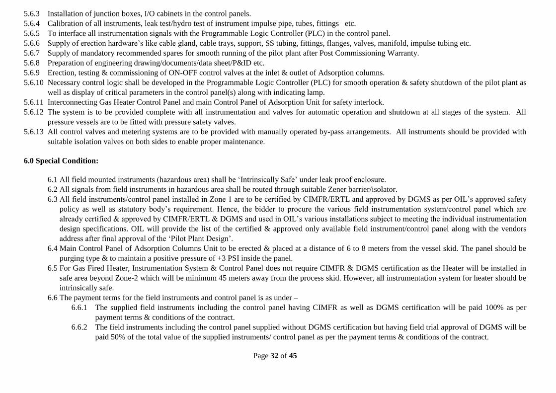
5.6.3 Installation of junction boxes, I/O cabinets in the control panels.
5.6.4 Calibration of all instruments, leak test/hydro test of instrument impulse pipe, tubes, fittings etc.
5.6.5 To interface all instrumentation signals with the Programmable Logic Controller (PLC) in the control panel.
5.6.6 Supply of erection hardware’s like cable gland, cable trays, support, SS tubing, fittings, flanges, valves, manifold, impulse tubing etc.
5.6.7 Supply of mandatory recommended spares for smooth running of the pilot plant after Post Commissioning Warranty.
5.6.8 Preparation of engineering drawing/documents/data sheet/P&ID etc.
5.6.9 Erection, testing & commissioning of ON-OFF control valves at the inlet & outlet of Adsorption columns.
5.6.10 Necessary control logic shall be developed in the Programmable Logic Controller (PLC) for smooth operation & safety shutdown of the pilot plant as
well as display of critical parameters in the control panel(s) along with indicating lamp.
5.6.11 Interconnecting Gas Heater Control Panel and main Control Panel of Adsorption Unit for safety interlock.
5.6.12 The system is to be provided complete with all instrumentation and valves for automatic operation and shutdown at all stages of the system. All
pressure vessels are to be fitted with pressure safety valves.
5.6.13 All control valves and metering systems are to be provided with manually operated by-pass arrangements. All instruments should be provided with
suitable isolation valves on both sides to enable proper maintenance.
6.0 Special Condition:
6.1 All field mounted instruments (hazardous area) shall be ‘Intrinsically Safe’ under leak proof enclosure.
6.2 All signals from field instruments in hazardous area shall be routed through suitable Zener barrier/isolator.
6.3 All field instruments/control panel installed in Zone 1 are to be certified by CIMFR/ERTL and approved by DGMS as per OIL’s approved safety
policy as well as statutory body’s requirement. Hence, the bidder to procure the various field instrumentation system/control panel which are
already certified & approved by CIMFR/ERTL & DGMS and used in OIL’s various installations subject to meeting the individual instrumentation
design specifications. OIL will provide the list of the certified & approved only available field instrument/control panel along with the vendors
address after final approval of the ‘Pilot Plant Design’.
6.4 Main Control Panel of Adsorption Columns Unit to be erected & placed at a distance of 6 to 8 meters from the vessel skid. The panel should be
purging type & to maintain a positive pressure of +3 PSI inside the panel.
6.5 For Gas Fired Heater, Instrumentation System & Control Panel does not require CIMFR & DGMS certification as the Heater will be installed in
safe area beyond Zone-2 which will be minimum 45 meters away from the process skid. However, all instrumentation system for heater should be
intrinsically safe.
6.6 The payment terms for the field instruments and control panel is as under –
6.6.1 The supplied field instruments including the control panel having CIMFR as well as DGMS certification will be paid 100% as per
payment terms & conditions of the contract.
6.6.2 The field instruments including the control panel supplied without DGMS certification but having field trial approval of DGMS will be
paid 50% of the total value of the supplied instruments/ control panel as per the payment terms & conditions of the contract.
Page 33 of 45
6.6.3 The bidder has to provide item wise cost break-up for all field instruments including control panel.
7.0 Inspection
Vendor to provide a schedule of onsite inspection for the manufacturing stages including bought-out items of instrumentation and controls with the tender at
Vendor’s Works. All materials to be used in the process of manufacturing are to be provided with test certificates. OIL‘s personnel may visit at any stages of
execution of the job for which necessary facility and co-operation will have to be extended by the vendor and minimum 15 days prior intimation is required
for schedule inspections.
8.0 Testing and Commissioning
8.1 The vendor will be responsible for testing and commissioning of the unit at site. The commissioning period will be for 3 days (72 hours) and will be
counted from the time when the plant becomes normal and operates as per design / ordered parameters. If the plant requires to be shut down before
completion of 03 days operation period due to malfunctioning of equipment, instruments etc. supplied by the vendor, 03 days operation period will
be counted afresh. Only after continuous operation of the unit for a period of 3 days (72 hours), it will be considered as commissioned successfully.
8.2 If any malfunction, abnormality occurs during trial/commissioning period, the party to rectify the same at their own expense.
9.0 Packing and Insulation
9.1 The equipment and skids are to be externally painted for environmental protection after thorough cleaning. As a minimum, this is to include zinc rich
primer (1 coat) and epoxy based final covering. Vendor to provide the proposed specification with his tender. Cleaning shall be done through sand
blasting before painting with spray.
9.2 The heater delivery line (hot surfaces) shall be properly insulated with and then covered with aluminum sheet jacket.
10.0 Guarantee
10.1 Vendor should stand guarantee for a period of 6 months from the date of successful commissioning of the plant for any type of mechanical,
instrumentation design failures including performance of the equipment and instruments at specified conditions.
10.2 Guarantee period will start from the date the plant operates satisfactorily as per design parameters and ordered specifications.
Page 34 of 45
11.0 Operation and Maintenance
11.1 The pilot plant is expected to operate for 3 (three) months (90 days) continuously for establishing the process parameters and operating principle for a
scaled up plant. The vendor shall have to provide round the clock operation and maintenance of the plant during this period. Accommodation and
transportation for the vendor’s staff during this period shall be arranged by the vendor. OIL may provide accommodation on chargeable basis.
11.2 Charges for operation and maintenance shall be quoted separately on per month basis.
12.0 Spares and adsorbents
Spares wherever required for successful testing, commissioning and operation of the unit after erection at the sites in all respect must be supplied by the
vendor at their own cost.
13.0 Exception and Deviation:
Vendor should mention separately, in clear terms the deviations and exclusions in his offer from the tender specification.
14.0 Delivery Schedule:
Bidders are to give their best realistic delivery schedule.
15.0 Bidding details:
The bidders should also include the following in their bid documents
15.1 An undertaking that detailed Mechanical/ Engineering Design with P&ID drawing along with electrical/PLC and structural layout will be submitted if
the order is placed on them.
15.2 At least 12 months warranty for the test facility along with all its components will be provided.
15.3 Complete information / data in order to avoid seeking any clarification on the bid documents.
15.4 Material Supply: Cost of the materials along with transportation charge, taxes and insurance, if any. The optional items indicated should be quoted
separately item wise.
15.5 Erection & Commissioning: Cost of erection and commissioning of the plant at OIL site.
15.6 In the price bid, bidders to quote the following:
15.6.1 Material Supply (Lump Sum): Cost of the materials alongwith transportation charge, taxes and insurance, if any.
15.6.2 Erection & Commissioning at site (Lump Sum) : Erection and commissioning of the plant.
Page 35 of 45
15.6.3 Operation & Maintenance (Per Month): Operation and Maintenance cost of the plant
15.7 After the placement of the order to the successful bidder, the party will be asked to:
15.7.1 Submit a detailed drawing and technical specification of all equipment of the test facility to OIL before fabrication for approval. P&ID,
different flow circuits, pressure/temperature control circuits etc. should also be included in this document.
15.7.2 Arrange for pre-delivery inspection
15.7.3 Ensure post-commissioning training to the OIL personnel for operation of the pilot plant.
*****************
SECTION # B
(i) For any HSE matters not specified in the contract document, the contractor will abide the relevant and prevailing Acts/rules/regulations/ pertaining to
Health, Safety and Environment.
(ii) Contractor will be allowed to work normally during working hours i.e. from 7 AM to 3 PM. Sometimes in special circumstances this duration may be
extendable upto 5 PM with due permission from Installation Manager / OIL's Engineer.
(iii)All expenses including air fare, boarding, lodging, enroute expenses etc. will be borne by the successful bidder.
(iv) All the required commissioning tools shall be arranged by the contractor.
(v) The site will be made available to vendor in properly graded condition. M/s. Oil India Limited will provide only necessary support during the
unloading and installation on the civil foundation.
(vi) For sampling purpose, sampling ports at inlet and outlet at designated locations with manual valves are to be provided.
***
Page 36 of 45
Annexure-II
Page 37 of 45
ANNEXURE-III
Detailed Process Description and Hardware Requirements
The following is a detailed description of the process (refer to process flow diagram in Fig. 1) along with hardware, instrumentation and other engineering
requirements. All the instrumentation (for measurement/control of temperature, pressure, flow, level, mass etc.) will include independent display units at a
suitable central location. All the adsorption columns / equipment will be exposed to around 300°C, all equipment /vessels instrument and materials shall be
selected accordingly. The design pressure should be 20 kg/cm2.
1.0 Process Gas: The process gas is a slip stream from an existing pipeline network at one of the gas collection stations (GCS) of OIL India limited. This
stream (S1) is passed through a filter separator to remove entrained liquid before splitting it into streams S2 and S3. The stream S2 will be the feed to
adsorption beds (max. flow rate of 1000 SCMD). The stream S3 is further split into S10 and S11 to be used in the regeneration step (max. flow rate of
1000 SCMD). The likely composition of this stream is as indicated in the Section 3.1 of Annexure I.
2.0 Filter separator: A chamber for efficient removal of entrained liquid in the gas/vapor stream has to be placed before the moisture removal column. This
operation may reduce the load on the column(s). The separator should be suitably designed to handle the throughputs expected during the operation. The
expected maximum flowrate of stream S1 is 2000 SCMD.
Monitoring & Control of Filter Separator should include:
Differential Pressure(DP) Gauge
Local pressure gauges for Inlet & Outlet of Filter Separator
Pressure transmitter in the filter separator outlet. The pressure transmitter signal to be feed to the Main Programmable Logic Controller for
controlling columns operation based on the minimum & maximum permissible pressure limit as per design basis.
3.0 Adsorber Columns: There are eight adsorption beds (B1-B8) in the unit. While beds B1 and B2 will be used for moisture removal, beds B3-B8 will be
used for removal of C5+heavy hydrocarbons. At any given time, one of the two beds (B1 or B2) will be in adsorption mode for removal of moisture, while
the other one will be in regeneration mode. Similarly three (B3-B5 or B6-B8) of the six beds will be in adsorption mode for removal of heavy hydrocarbons,
while the other three will be in the regeneration mode.
Each beds should be suitably designed to contain the adsorbent material with appropriate support screens. A suitable design should also be provided for good
distribution of gas/vapors at the top and bottom of each one of the beds.
All the above adsorption beds shall be complete with necessary instrument, controls for automatic switching of adsorption and regeneration (desorption)
cycles. Valves and timers are needed for switch over of streams between adsorption and regeneration beds as described in the process.
Monitoring & Control of Adsorption beds should have the following specifications:
ON/OFF control valves as indicated in the Process flow diagram (Annexure II).
Page 38 of 45
Automatic changeover of columns from adsorption to regeneration & vice versa after completion of definite time cycle operation, sequence of
operation of control valves either in ON or OFF mode in the inlet & outlet sections of the respective columns through a dedicated Programmable
Logic Controller (PLC). Provision for automatic emergency safety shutdown, manual step-up & step-down of time cycle operation of adsorption
columns & manual changeover of adsorption column whenever process condition demands. In addition, provision should also be available to operate
valves such that the beds B3-B5 (and B6-B8) can be run either in series or in a parallel fashion to accept the feed or regeneration gas.
Pressure Transmitter(s) for adsorption columns (Total 8 nos. one each for beds B1-B8).
RTDs with thermowell along the height of each bed spaced at a distance of about 1 meter.
Temperature transmitters for all the above RTDs
Pressure gauges on each columns for local indication
Pressure & temperature switches for each columns for safety shutdown
Limit switches/LVDT for columns inlet & outlet valves status like ON/OFF and opening/closing position & sequence interlock and safety shutdown.
4.0 Column packing: The columns will be packed with suitable adsorbent materials. The beds B1 and B2 will be packed with 4A molecular sieves (1/16”
pellets). Beds B3-B8 will be packed with Silica Gel beads 2‐ 5 mm.
The physical properties of the adsorbents to be supplied are as follows.
Molecular sieve 4A:
o Size: 1/16” pellets or 2-4 mm spherical beads
o Water adsorption capacity: 20 wt % minimum at 18 mm Hg and 25°C
Silica gel
o Size: 2-5 mm spherical beads
o Pure methane (CH4) capacity: not more than 11 cc at STP/gm of silica gel at partial pressure of 9 bar and 20°C and not more than 6 cc at
STP/gm of silica gel at partial pressure of 93 bar and 75°C.
o Pure n-pentane (C5H12) capacity: At least 40 cc at STP/gm of silica gel at partial pressure of 0.3 bar and 20°C and at least 6.5 cc at STP/gm of
silica gel at partial pressure of 0.3 bar and 75°C.
o BET Surface area: Minimum 550 m2/g
The adsorbents should be procured from reputed vendors such as Linde, UOP, M/s Chemicals India Company, M/s Drier Chemicals, M/s Sud Chemie etc.
The samples should be validated with OIL before actual purchase by the vendor.
5.0 Electric heater: For heating the process gas to be used in regeneration of the adsorbent beds, two electric heaters (one each for hydrocarbon removal
and moisture removal sections) will be used. A dedicated temperature control function for maintaining the regeneration gas temperature between 130 -
300 deg C should be provided for each one of the heaters.
Temperature transmitter(s) and display units including provision for local display
Heater temperature transmitter for indication & safety shutdown
Emergency manual shutdown, temperature & pressure indications, indicating Lamp etc. should be included along with all standard accessories as per
standard engineering practice.
Page 39 of 45
All electric heaters should be provided with automatic bypass valves.
6.0 Gas Cooler: A intermediate gas cooler is to be provided in stream S4, to cool the dehydrated gas (max. flow rate 1000 SCMD). The heat exchanger
should be designed to cool the gas by 50 deg C. Running utility water for the cooler will be available, if necessary.
7.0 Pressure Control Valve with pressure controller: Up-stream control valve will be used for transferring process lean gas to Low Pressure system.
8.0 Check valve: Check valves will be used as necessary to ensure one way flow of regeneration wet gas into the LP unit. In addition, check valves
should be included at other locations as per standard engineering practice.
9.0 Gas Flow Measurement and Control Valve flow controller:
Monitoring & Control of gas flow measurement and flow control should have the following specifications:
Gas Flow Measurement & flow control are need in streams S2, S8, S9, S10 and S11 (Annexure II).
For Gas Flow Application (flow measurement) multivariable transmitter along with orifice plate shall be used.
All the above Gas Flow Calculation to be done in PLC with necessary programming software meeting requirement as per AGA-3.
Multivariable transmitter shall be of electronic smart type transmitter compatible with fieldbus protocol of latest version with capability to handshake
with any communicating device. This transmitter shall have RTD connectivity also for flow calculation as well as transmitting temperature to PLC.
Accuracy of the transmitter should not be degraded beyond ±0.15%.
PLC’s must be compatible for gas flow allocution with sufficient memory (RAM) and display must be in the TFT display monitor.
Control valve(s) with positioned & I/P converter and flow control action (PD or PID) from main Programmable Logic Controller (PLC).
10.0 Temperature indicators, transmitters and controllers: The pilot plant is being installed as a R&D unit. The process data will be collected
extensively. Hence, several temperature transmitters are to be placed along the length of the beds as indicated in section 3.0 in this annexure. All
temperature transmitters in the adsorber beds will be well inserted into the solid adsorbent bed and be hermitically sealed. In addition to the above
temperature transmitters and that needed in the temperature control in the heaters, additional transmitters as needed in the process unit as per standard
engineering practice should be included. All the temperature transmitters should be linked to the PLC display.
All the transmitters will be 4-wire duplex RTD and thermo well’s immersion length shall be suitable for the line size. RTD element shall be Pt 100 and
it will be as per DIN 43760 and accuracy will be class A.
11.0 Pressure indicators, transmitters and gauges: In addition to the pressure transducers on the adsorber columns as indicated in section 3.0 in this
annexure and in the electric heater units, additional pressure transmitters are needed for streams S2, S3, S6, S12, S14, S15 and S17. Additional
transmitters as per standard engineering practice and necessary for safe operation of the unit should also be included. All pressure transducers should be
linked to the PLC. Pressure gauges shall be provided at several locations in the process unit for local monitoring as per standard engineering practice.
12.0 Pressure safety valves: All the adsorber columns and heaters and other sub-units of the process should be equipped with suitable pressure safety valves
to prevent over pressurization.
Page 40 of 45
13.0 Sampling points: Sampling points on the gas lines will be suitably designed along with necessary manual valves, so that samples can be withdrawn
safely for analysis. The sampling points to withdraw gas samples shall be provided on S2, S4, S5 (3 nos.), S12, S14, S15 and S17 (3 nos.).
14.0 Insulation: All the pipelines for hot regeneration gas streams will be well insulated to minimize heat loss as described in section 9 of Annexure I.
15.0 Valves:
The valves shall be selected as per the process condition and shall be procured from L&T, Virgo Valves & Controls. For hydrocarbon service, ball
valves to be used.
Valve trim in hydrocarbon service shall be suitable for hydrocarbon with 10% carbon dioxide.
All valves shall be of fire safe type as per API 1607 / BS 5146. Fire safe test shall be as per the standard and test certificate shall be furnished.
Body, bonnet, cover etc. of all valves shall be from carbon steel casting or forged steel. Steel casting or forging shall be of radiographic quality as per
procedure and acceptance criteria specified in ANSI B 16.34 – 1977.
All valves shall be with flanged ends as per ANSI B 16.5.
In addition to the ON/OFF valves indicated in the process flow diagram all the sections of the unit should be equipped with isolation valves (not
included/shown in the PFD) as per standard practice.
All solenoid valves to be housed in a separate enclosure with proper air supply regulator & filters assembly and to be placed near the near the main
control panel for interlinking.
16.0 Control panel:
A dedicated main control panel for the adsorption columns which will comprise of Master Programmable Logic Controller, critical parameters
display along with indicating lamps, start/stop & sequence of columns operation after getting required feedback signal (safety interlock) from the
electric Heater & vice versa, all standard accessories in the control panel as per standard engineering practice.
All field instruments shall be hooked up with the respective PLC control panel for necessary start/stop, display& monitoring, sequence interlock &
safety shutdown, gas flow calculation as per AGA-3. All control logic for sequence of operation and safety shutdown of the unit to be developed
accordingly.
The unit will be controlled through a single PLC placed at a suitable location. A high resolution (1024 x 768, 18-bit color graphics) TFT display
monitor unit with touch screen/ key board for monitoring of all parameters like Pressure, Temperature, Flow, Valves status(ON/OFF) etc.
including alarm & graphical display shall be considered in PLC control panel. This LCD display unit shall be hooked up with the PLC through
suitable communication protocol (Ethernet, RS 232, RS 485 etc.).
Based on the process flow diagram (Annexure II), total requirement of field & control instrumentation system for the entire process unit should be
assessed and instrumentation should be designed accordingly. This should include implementation of complete operation logic, sequence of
control operation and safety shutdown.
Page 41 of 45
Field Transmitters should be intrinsically safe under leak proof enclosure for use in hazardous area. Function of the transmitter shall be
transmission as well as indication. Type of transmitter shall be of electronic smart type transmitter compatible with fieldbus protocol of latest
version with capability to handshake with any communicating device. The enclosure should be weather proof to IP 65.
17.0 Pipes and Fittings:
All piping materials and fabrication shall conform to ANSI B 31.3 (latest edition).
All carbon steel fittings shall be as per ASTM A 234 WPB seamless.
The vendor shall provide and connect all inter- all drain headers etc. Spool pieces, if required shall be provided to finally connect by the bidder to
adjacent skids (if the number of skids is more than one) together at site.
All connection in piping, valves etc. shall be through weld neck forged carbon steel flanges as per ANSI B 16.5.
All pipe fittings shall be from carbon steel made through forging. Fabricated fittings such as bends, elbows, tees etc. made through welding are not
allowed.
All welding joints shall be of radiographic quality as per API 1104 and at least 20% of the welding joints shall be radio graphed and radiographic
films submitted to OIL.
Piping shall be arranged in such a manner to avoid crisscrossing or overhead problems. Piping or tubing of insufficient mechanical strength for
standing or hanging shall be protected from personnel traffic.
All sub-suppliers items e.g., instruments, valves, pipes fittings etc. shall be from reputed manufacturer / supplier and should conform to relevant codes
and standards.
Since the plant equipment will be exposed to about 300 deg C, all valves /pipes / pipe fitting metallurgy shall be selected accordingly.
18.0 Material of Construction: The materials to be used as follows.
Vessels / Tanks : SA-515 Gr. 60 / 70 / IS:2002 Gr. 2
Shell flanges : SA-105
Nozzle flanges : SA-105
Supports : SA-283 Gr. C/IS:226
Nuts & Bolts : SA 193 Gr. B7, SA 194 Gr. 2H
Pipes, flanges and fittings : ANSI B31.3 / API 51 / ANSI B16.5
Instrument piping : Annealed seamless 316 stainless steel with Swagelok type fittings
19.0 Codes and Standards: The latest editions of ASME VIII DIV. 1, ASME Section IX, ANSI B 16.5 and ANSI B 31.3 will apply.
Page 42 of 45
20.0 Mounting: The pilot plant unit will be skid mounted suitably. Each unit like adsorption column, heater, filter etc along with its instruments should be
skid mounted. The skids should be fabricated from suitable structural steel section. The skids must be rugged and compact, being designed for
transportation by trailer and fitted with two bars. Vendor to provide lifting arrangements for all the skids and minimum number of skid should be
employed. Details of bolting down for skids to be provided by vendor.
21.0 Instrumentation Data Sheets: The instrumentation data sheets for various hardware are given in Annexure IV. Any items not included in the list will
be chosen by vendor in such a way that safe and reliable operation of the process unit is ensured. 22.0 Suggested Vendor List: A suggested vendor list for various components of the test facility instrumentation systems is indicated below. The third-party
supplier for the pilot plant will be asked to use components only from the suggested vendors. In case of non-availability of any component
manufactured by the listed vendor(s) during the time of procurement and fabrication of the pilot plant, other product with similar specifications/quality
from other reputed vendors (with proper documentation and justification) may also be considered with prior approval of OIL. For any components, not
mentioned in the list below but required to be incorporated in the testing unit, the successful bidder may suggest a list of vendors for those components
and get approval from OIL before procuring and using them in the pilot plant.
22.1 24 V DC Power Supply Phoenix/Silop
22.2 Air Filter Regulator Shavonorgren/Placka
22.3 Alarm Annunciator IIC/Procon/ Murphy
22.4 Ball Valves (for impulse line0
Flow Control/L&T/Flow Chem
22.5 Cable Gland Baliga/Electromac
22.6 Chemically treated earth pit
Ashlok/Welcome World Engg/Power gomengg
22.7 Circuit Breaker (Inside panel)
GE/Siemens/Schneider
22.8 Control Panel Rittal/Pyrotech/ICA/Altronic/Murphy
22.9 Control switches KAYCEE/ Siemens
22.10 Control Valves Fisher / Fouress / Instrumentation Ltd.
22.11 Digital Panel Indicator Masibus/Honeywell/ABB
5.3 Type Electronic Smart Type with any protocol(Analog, HART, FF etc)
5.4 Class MFR Std
5.5 Mounting Yoke
5.6 Protection Class Intrinsically Safe EExia and Weather proof to IP 65 as per IEC 60529/ IS 2147
5.7 Electrical Area Classification
IEC Zone 2, Gas Group II A/II B, T6
5.8 Intrinsically Safe Yes
5.9 Power Supply 24 V DC
5.10 Cable Entry ½” NPT(F) with SS plug
5.11 Accuracy +/- 0.075% of span
5.12 Rangeability 40:1 or better
5.13 Transmitter Output 4-20 mA DC
5.14 Load Capability 600 ohm at 24 V DC
5.15 Service Natural Gas
5.16 Element Diaphragm
5.17 Body Material SS316
5.18 Element Material SS316L
5.19 Process Connection ½”NPT(F) or 3/8” NPT(F)
5.19.1 Process Connection Location
Bottom
5.20 Fill Fluid Silicone Oil
5.21 Zero & Span Adjustment
Non-interactive Type
5.22 Zero Suppression & Elevation
100% of span continuously adjustable externally
5.23 Adapter ‘O’ Ring PTFE
5.24 Over Range Protection Yes
5.25 Options
5.25.1 Intrinsically safe Output Meter(LCD)
Yes in Engg. Unit
5.25.2 Mounting Accessories suitable for 2” NB Pipe
Yes
5.25.3 2 Valve Manifold Yes
6.0 Data Sheet of Pressure Switch
6.1 Type Seal Diaphragm, Piston Actuated
6.2 Sensing Element Material
AISI SS-316 Diaphragm/Piston. All other wetted part SS-316
6.3 Case Material Epoxy coated steel plate or die-cast aluminium with neoprene gasket and clear glass. Cover conforming to IP-65( Explosion proof for NEC Class 1, Division 1 Area)
6.4 Setter Scale Black graduation on white liner scale. Graduation 0-100% with red pointer for set points
6.5 Over Range 150% of maximum pressure
6.6 Adjustments (a) Internal Set point (b) Internal Differential adjustment nut with dial for at least
10% of span(min.)
6.7 Process connection Suitable as per design basis( or any ½” NPT(M) / 3/8” NPT(M)/ ¼” NPT(M) bottom connected)
6.8 Switch Configuration Two SPDT
6.9 Switch Rating 240 V, 5 A AC / 220 V, 0.5 A DC
6.10 Switch Type Snap Acting, Shock & Vibration proof
6.11 Adjustability a) Set point adjustable over span range b) Differential adjustment by 10 percentage of span(min.)
6.12 Sealing ring Viton, Buna-N
6.13 Terminal Block Suitable for full ring lugs for cable connections
6.14 Cable Connection ½” NPT(F) or 3/8” NPT(F) or ¼” NPT(F)Conduit connection or compression gland(as per design requirement)
6.15 Enclosure class IP 65
6.16 Performance Accuracy ± 1%, Accuracy of setting indication of ± 1.5%
6.17 Name Plate Tag number, services engraved in stainless steel Tag plate
7.0 Data Sheet of Control Panel
7.1 Type Enclosed self-supporting
7.2 Material Heavy gauge CRCA sheet steel, reinforced to provide self-standing and rigid assembly
7.3 Thickness Not less than 3 mm
7.4 Surfacing Clean and smooth finish with anti-rust and anti-corrosion primer coating
7.5 Color
7.5.1 External Light Grey
7.5.2 Internal Glossy white
7.6 Dimensions As per design standard
7.7 Enclosure class IP-65
7.8 Temperature
7.8.1 Environment Maximum 50 deg C
7.8.2 Internal temperature control
Maintained at optimum value for system equipment
7.9 Door location Back with door latch (removable)
7.10 Cable connection Plug in
7.11 Process signaltermination practice
Screwed, terminal point, wire wrap or manufacturer’s standard with 100 mm (minimum) gap between terminal block
7.12 Card mounting As per PLCstandard rack
7.13 Wiring
7.13.1 Terminal blocklocation
30 cm above floor, easy accessible and maintenance
7.13.2 No of processTermination per Terminal
Two (2) maximum
7.13.3 Insulation grade 600 V or above
7.13.4 Designation All cables shall be marked for identification by color code wires etc
7.13.5 Termination spare
20% after complete installation
7.13.6 Cable and fitting
Prefabricated cable from process termination to the system cabinet with connection on both sides.
7.13.7 Internal wiring One fused terminal block with required glass fuse rating for each input and output.
7.14 Isolation All circuit including shield isolated from cabinet
7.15 Panel lighting Panel tube light should be ON while opening the door
8.0 Data Sheet of TFT Display Monitor
8.1 Operator Input Keypad, Touch, or Key/Touch
8.2 Display Description Color active-matrix TFT
8.3 Display Size 15 inch
8.4 Display Area (WxH) 304 x 228 mm (12.0 x 9.0 in)
8.5 Resolution 1024 x 768, 18-bit color graphics
8.6 Luminance 300 cd/m2 Nits
8.7 Backlight 50,000 h life, min., field replaceable
8.8 Real-time Clock Battery backed clock timestamps critical data, ± 2 minutes per month Battery life: 4 year min. @ 25 °C (77 °F)
8.9 Touch Screen Description
8-wire analog resistive Actuation: 1 million presses; operating force: 10…110 g
8.10 Keypad Description
Stainless-steel membrane Numeric, navigation, and function keys Actuation: 1 million presses; operating force: 10…340 g
8.11 Function Keys 40 (F1…F20, K1…K20)
8.12 Operating Systems Windows CE 6.0 with extended features/file viewers or better
8.13 Application Software
FactoryTalk View Machine Edition FactoryTalk ViewPoint, version 1.2 or later
8.14 Memory 512 MB nonvolatile flash and 512 MB RAM
8.15 Communication Ports
Ethernet (10/100 Mbps, Auto-MDI/MDI-X), RS-232, (2) USB host, (1) USB device, Network interface for optional DH+/DH-485, or ControlNet (scheduled or unscheduled) communication module
8.16 External storage
Secure Digital (SD) card, supported by hot-swappable SD card slot USB flash drives supported by high-speed, hot-swappable, 2.0 USB ports
8.17 Input Voltage AC AC: 85…264V AC, 47…63 Hz
8.17.2 Input Voltage DC DC 18…32V DC (24V DC nominal)
8.18 Power Consumption
8.18.1 Power Consumption, AC
160VA max
8.18.2 Power Consumption, DC
70 W (2.9 A at 24V DC)
8.19 Operating Temperature 0…55 °C (32…131 °F)
8.20 Dimension
8.20.1 Keypad (HxWxD) or Key/Touch
330 x 469 x 65 mm 12.97 x 18.46 x 2.55 in.
8.20.2 Touch Screen (HxWxD) 330 x 416 x 65 mm 12.97 x 16.37 x 2.55 in.
9.0 Data Sheet of Solenoid valve
9.1 Type NORMALLY CLOSED DIRECT ACTING (3 way normally closed input port connected to out port, energized- out put port connected to exhaust)
9.2 Size Port size:1/4", Connection size: 1/2" NPT
9.3 Protection Class Intrinsically safe ,Flameproof, IP-67, All construction safety as per IEC61508, Suitable for Zone-1 Zone 2 hazardous area
9.4 Power Supply 24 V DC
9.5 Enclosure Electrical enclosure as per EN 60529, Aluminium IP-67, Zone II 2/G/D Eexd IIC T6, T4 IP 67
9.6 Service AIR & Natural Gas
9.7 Body/Material 316SS, CORE & PLUG NET 430F SS, CORE TUBE 303 SS or 304 SS
9.8 RIDER RING PTFE
9.9 SPRINGS 303 SS or 304 SS
9.10 Duty Continuous, heavy duty
9.11 WATTAGE 0.7 TO 12 WATT
10.0 General Data Sheet of PLC (Programmable Logic Controller)
10.1 Make Preferably Allen Bradley
10.2 Total number of points As per design
10.3 No of Instruction As per design
10.4 No of Inputs/Outputs As per design
10.5 Input Type Analog/Digital/AC/DC/RTD/Thermocuple/All types of FieldBus protocol etc
10.6 Output Type Analog/Digital/AC/DC/RTD/Thermocuple/All types of FieldBus protocol etc
10.7 Processor 32/64 bit processor, maximum 0.5 micro seconds cycle time/1k words
10.8 flash memory(non-volatile)
Maximum 128 MB
10.9 User Memory 384 KB to 3 MB
10.10 Expandable Yes
10.11 Maximum no of channels As per design basis of I/O
10.12 Programming Computer programmable
10.13 PLC Programming Software
LD/SFC/IL/FBD/ST/RLL
10.14 Application Software Gas Flow Calculation Software as AGA-3 for main PLC
10.15 Power 24 V DC/230 V AC
10.16 Communication Port For Heater PLC: Ethernet- 1 no, RS 232: 1no For Main PLC: Ethernet-1 no, RS232- 2no
10.17 Controller Task Maximum 32 tasks, Maximum 100 programs/ tasks
10.18 Controller Application General purpose, Small to medium size applications
10.19 Features Visual LED indicators/Non-volatile Memory(EEPROM)/Integral Power Supply/Surge Protection/ Timer(s)/Counter(s)