OIL INDIA LIMITED (A Government of India Enterprises) PO : Duliajan – 786602 Assam (India) TELEPHONE NO. (91-374) 2808719 FAX NO: (91-374) 2800533 Email: [email protected] ; [email protected]TENDER NO. SDI2535P12 DATE: 30.06.2011 INVITATION TO e-BID UNDER SINGLE STAGE TWO BID SYSTEM Dear Sirs, OIL invites Bids for Design, Engineering, Supply, Installation, Testing and Integration of Radio Communication system through its e-Procurement site under SINGLE STAGE TWO BID SYSTEM. The bidding documents and other terms and conditions are available at Booklet No. MM/LOCAL/E-01/2005 for E-Procurement LCB Tenders. The prescribed Bid Forms for submission of bids are available in the tender document folder. The general details of tender can be viewed at ‘Basic data’ under ‘Header data’ in Bid invitation screen. The details of items tendered can be found by clicking to ‘Item data’. The tender is invited with firm price for the specified quantity. Further details of tender are given in C FOLDER as ANNEXURE 1A The tender will be governed by: a) “General Terms & Conditions” for e-Procurement as per Booklet No. MM/LOCAL/E-01/2005 for E-Procurement LCB Tenders. b) Technical specifications and Quantity as per Annexure – 1A. c) Offers should be valid for minimum 120 days from the date of Technical Bid closing Date, failing which offer shall be rejected. d) The prescribed Bid Forms for submission of bids are available in the tender document folder. Technical Checklist and Commercial Checklist vide Annexure VI must be filled-up and submitted along with the technical bid. e) In the event of receipt of only a single offer against the tender within B.C. date, OIL reserves the right to extend the B.C. date as deemed fit by the Company. During the extended period, the bidders who have already submitted the bids on or before the original B.C. date, shall not be permitted to revise their quotation. f) Any sum of money due and payable to the contractor (including Security Deposit refundable to them) under this or any other contract may be appropriated by Oil India Limited and set-off against any claim of Oil India Limited (or such other person or persons contracting through Oil India Limited) for payment of sum of money arising out of this contract or under any other contract made by the
Transcript
OIL INDIA LIMITED
(A Government of India Enterprises) PO : Duliajan – 786602
INVITATION TO e-BID UNDER SINGLE STAGE TWO BID SYSTEM Dear Sirs, OIL invites Bids for Design, Engineering, Supply, Installation, Testing and Integration of Radio Communication system through its e-Procurement site under SINGLE STAGE TWO BID SYSTEM. The bidding documents and other terms and conditions are available at Booklet No. MM/LOCAL/E-01/2005 for E-Procurement LCB Tenders. The prescribed Bid Forms for submission of bids are available in the tender document folder. The general details of tender can be viewed at ‘Basic data’ under ‘Header data’ in Bid invitation screen. The details of items tendered can be found by clicking to ‘Item data’. The tender is invited with firm price for the specified quantity. Further details of tender are given in C FOLDER as ANNEXURE 1A The tender will be governed by: a) “General Terms & Conditions” for e-Procurement as per Booklet No.
MM/LOCAL/E-01/2005 for E-Procurement LCB Tenders. b) Technical specifications and Quantity as per Annexure – 1A. c) Offers should be valid for minimum 120 days from the date of Technical Bid
closing Date, failing which offer shall be rejected.
d) The prescribed Bid Forms for submission of bids are available in the tender document folder. Technical Checklist and Commercial Checklist vide Annexure VI must be filled-up and submitted along with the technical bid.
e) In the event of receipt of only a single offer against the tender within B.C. date, OIL reserves the right to extend the B.C. date as deemed fit by the Company. During the extended period, the bidders who have already submitted the bids on or before the original B.C. date, shall not be permitted to revise their quotation.
f) Any sum of money due and payable to the contractor (including Security Deposit refundable to them) under this or any other contract may be appropriated by Oil India Limited and set-off against any claim of Oil India Limited (or such other person or persons contracting through Oil India Limited) for payment of sum of money arising out of this contract or under any other contract made by the
contractor with Oil India Limited (or such other person or persons contracting through Oil India Limited).
Special Note: 1.0 To be eligible for participation in the above tender the applicant must meet the following qualifying criteria (documentary evidence to be provided). i). Successful execution of a single order of value not less than ` 295.03 Lakhs for supply
of similar items during last five years. ii). Annual turnover of the firm in any of the last three financial years or current
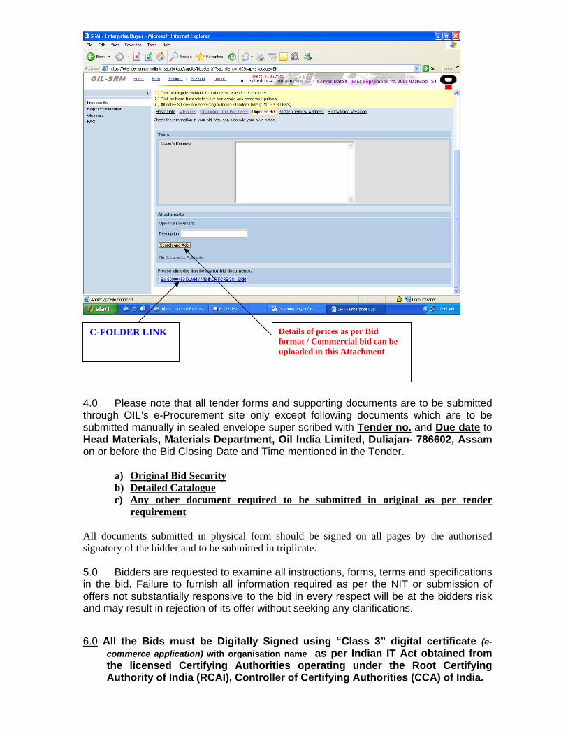
financial year should be more than ` 590.06 Lakhs. 2.0 Application showing full address/email address with Tender Fee (Non - refundable) of Rs. 1000.00 (Excepting PSUs and SSI unit registered with NSIC) by D/Draft in favour of M/s Oil India Limited and payable at Duliajan is to be sent to Head-Materials, Oil India Limited, P.O. Duliajan, Assam-786602 only between 20.07.2011 and one week prior to Bid Closing date. On receipt of requisite tender fee and subject to fulfillment of eligibility criteria, USER_ID and initial PASSWORD will be communicated to the bidder (through e-mail) and will be allowed to participate in the tender through OIL’s e-Procurement portal. No physical tender documents will be provided. 3.0 The tender is invited under SINGLE STAGE-TWO BID SYSTEM. The bidders are required to submit both the “TECHNICAL” and “COMMERCIAL” bids through electronic format in the OIL’s e-Tender portal within the Bid Closing Date and Time stipulated in the e-Tender. Please ensure that Technical Bid / all technical related documents related to the tender are uploaded in the c-Folder link (collaboration link) under Un-priced Bid Tab Page only. Please note that no price details should be uploaded as c-Folder link (collaboration link) under Un-priced Bid Tab Page. Details of prices as per Bid format / Commercial bid can be uploaded as Attachment in the attachment link under “Unpriced Bid” under “General Data”. A screen shot in this regard is given below. Offer not complying with above submission procedure will be rejected as per Bid Rejection Criteria mentioned in Annexure-II
4.0 Please note that all tender forms and supporting documents are to be submitted through OIL’s e-Procurement site only except following documents which are to be submitted manually in sealed envelope super scribed with Tender no. and Due date to Head Materials, Materials Department, Oil India Limited, Duliajan- 786602, Assam on or before the Bid Closing Date and Time mentioned in the Tender.
a) Original Bid Security b) Detailed Catalogue c) Any other document required to be submitted in original as per tender
requirement All documents submitted in physical form should be signed on all pages by the authorised signatory of the bidder and to be submitted in triplicate. 5.0 Bidders are requested to examine all instructions, forms, terms and specifications in the bid. Failure to furnish all information required as per the NIT or submission of offers not substantially responsive to the bid in every respect will be at the bidders risk and may result in rejection of its offer without seeking any clarifications.
6.0 All the Bids must be Digitally Signed using “Class 3” digital certificate (e-commerce application) with organisation name as per Indian IT Act obtained from the licensed Certifying Authorities operating under the Root Certifying Authority of India (RCAI), Controller of Certifying Authorities (CCA) of India.
Details of prices as per Bid format / Commercial bid can be uploaded in this Attachment
C-FOLDER LINK
7.0 Bidders must ensure that their bid is uploaded in the system before the tender closing date and time. Also, they must ensure that above documents which are to be submitted in a sealed envelope are also submitted at the above mentioned address before the bid closing date and time failing which the offer shall be rejected.
8.0 Single stage Two bid system shall be followed for this tender and only the price-bids of the bidders whose offers are commercially and technically acceptable shall be opened for further evaluation.
9.0 The Integrity Pact is applicable against this tender. OIL shall be entering into an Integrity Pact with the bidders as per format enclosed vide Annexure V of the tender document. This Integrity Pact proforma has been duly signed digitally by OIL’s competent signatory. The proforma has to be returned by the bidder (along with the technical bid) duly signed (digitally) by the same signatory who signed the bid, i.e., who is duly authorized to sign the bid. Any bid not accompanied by Integrity Pact Proforma duly signed (digitally) by the bidder shall be rejected straightway. Uploading the Integrity Pact with digital signature will be construed that all pages of the Integrity Pact has been signed by the bidder’s authorized signatory who sign the Bid.
10.0 The tender shall be governed by the Bid Rejection & Bid Rejection Criteria given in enclosed Annexure – II. However, if any of the Clauses of the Bid Rejection Criteria / Bid Evaluation Criteria (as per Annexure-II) contradict the Clauses of the tender and / or “General Terms & Conditions” as per Booklet No. MM/LOCAL/E-01/2005 for E-procurement (LCB Tenders) elsewhere, those in the BEC / BRC shall prevail.
Yours Faithfully Sd- (S HAZARI) SENIOR PURCHASE OFFICER (ID) FOR : HEAD-MATERIALS
OIL INDIA LIMITED
ANNEXURE-IA Tender No & Date : SDI2535P12 Dated 30.06.2011 Tender Fee : INR 1000.00 Bid Security Amount : INR 11,35,000.00 Bidding Type : SINGLE STAGE TWO BID SYSTEM Bid Closing on : As mentioned in the Basic Data of e-portal Bid Opening on : -do- Performance Guarantee : Applicable OIL INDIA LIMITED invites Indigenous tenders for items detailed below:
TECHNICAL SPECIFICATIONS WITH QUANTITY
SECTION A SH 1 OF 1 1.0 SCOPE OF ENQUIRY 1.1 This procurement specification covers design, engineering, supply, packing, transportation
from place of manufacture to site, installation, testing, integration with the existing LAN and Central EPABX system, startup, commissioning and performance testing of the Radio communication (5.8 GHz licence free ISM band) system for voice, data Intranet, Internet, SCADA, surveillance and ERP applications on Turn Key basis.
1.2 The Tender document includes the detailed information of the project (SECTION B), Scope of Supply, Works & Services (SECTION C), Technical Specifications and Special Conditions (SECTION D), other requisite formats (SECTION E) and Bid Rejection Criteria / Bid Evaluation Criteria (BEC / BRC).
1.3 Bidders must take cognizance of all the sections of this document. Similarly, bidders must submit their price bids and Summary of Prices as per the formats given in SECTION E1. This tender is subjected to BEC/BRC as per ANNEXURE-II.
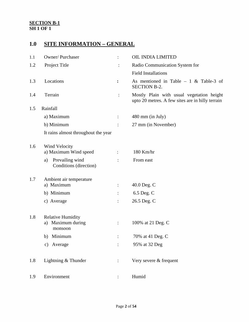
1.2 Project Title : Radio Communication System for
Field Installations
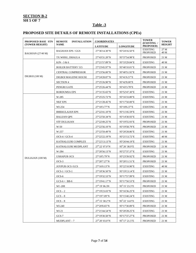
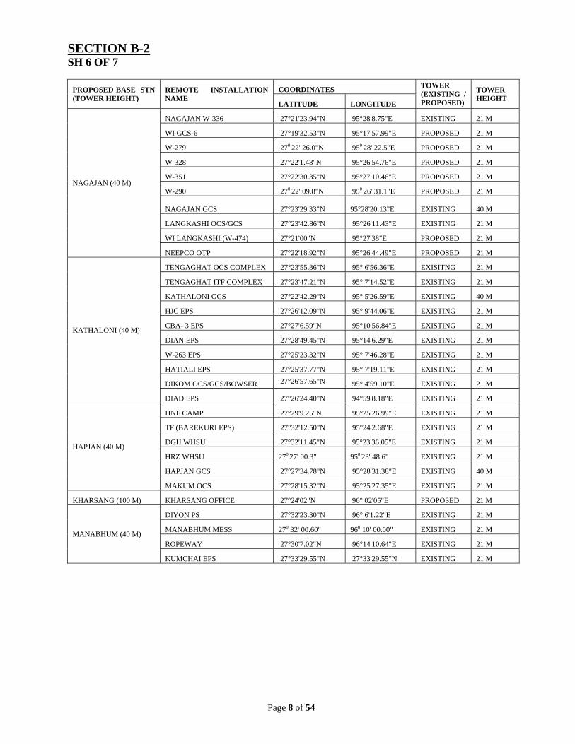
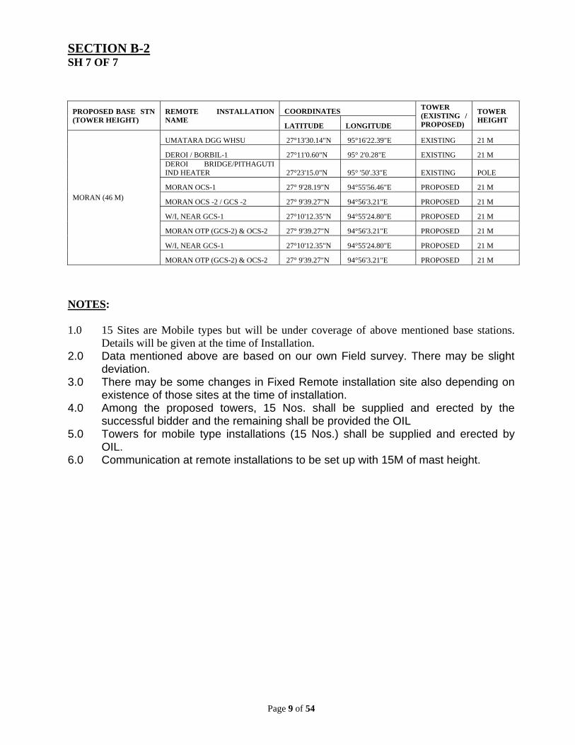
1.3 Locations : As mentioned in Table – 1 & Table-3 of SECTION B-2.
1.4 Terrain : Mostly Plain with usual vegetation height upto 20 metres. A few sites are in hilly terrain
1.5 Rainfall
a) Maximum : 480 mm (in July)
b) Minimum : 27 mm (in November)
It rains almost throughout the year
1.6 Wind Velocity
a) Maximum Wind speed : 180 Km/hr
a) Prevailing wind : From east Conditions (direction)
1.7 Ambient air temperature
a) Maximum : 40.0 Deg. C
b) Minimum : 6.5 Deg. C
c) Average : 26.5 Deg. C
1.8 Relative Humidity a) Maximum during : 100% at 21 Deg. C
monsoon
b) Minimum : 70% at 41 Deg. C
c) Average : 95% at 32 Deg
1.8 Lightning & Thunder : Very severe & frequent
1.9 Environment : Humid
Page 3 of 54
SECTION B-2 SH 1 OF 7 1.0 PROJECT INFORMATION : BRIEF DESCRIPTION OF PROJECT &
EXISTING NETWORK DETAILS
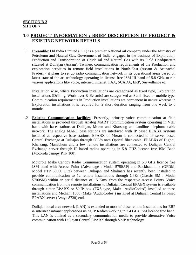
1.1 Preamble: Oil India Limited (OIL) is a premier National oil company under the Ministry of Petroleum and Natural Gas, Government of India, engaged in the business of Exploration, Production and Transportation of Crude oil and Natural Gas with its Field Headquarters situated at Duliajan (Assam). To meet communication requirements of the Production and exploration activities in remote field installations in North-East (Assam & Arunachal Pradesh), it plans to set up radio communication network in its operational areas based on latest state-of-the-art technology operating in license free ISM-III band of 5.8 GHz to run various applications like voice, internet, intranet, FAX, SCADA, ERP, Surveillance etc. . Installation wise, where Production installations are categorized as fixed type, Exploration installations (Drilling, Work-over & Seismic) are categorized as Semi fixed or mobile type. Communication requirements in Production installations are permanent in nature whereas in Exploration installations it is required for a short duration ranging from one week to 6 months.
1.2 Existing Communication facilities: Presently, primary voice communication at field installations is provided through Analog MART communication system operating in VHF band with base stations at Duliajan, Moran and Kharsang and landline telephone cable network. The analog MART base stations are interfaced with IP based EPABX systems installed at respective base stations. EPABX of Moran is connected to IP server based Central Exchange at Duliajan through OIL’s own Optical fiber cable. EPABXs of Digboi, Kharsang, Manabhum and a few remote installations are connected to Duliajan Central Exchange server through IP based radios operating in 5.8 GHZ licence free ISM Band (Motorola canopy PTP 100).
Motorola Make Canopy Radio Communication system operating in 5.8 GHz licence free ISM band with Access Point (Advantage : Model 5750AP) and Backhaul link (OFDM, Model PTP 58500 Lite) between Duliajan and Shalmari has recently been installed to provide communication to 12 remote installations through CPEs (Classic SM : Model 5700SM) within an aerial distance of 15 Kms. from the respective Access Points. Voice communication from the remote installations to Duliajan Central EPABX system is available through either EPABX or VoIP box (FXS type, Make ‘AudioCodes’) installed at these installations and Mediant 1000 (Make ‘AudioCodes’) installed at Duliajan Central IP based EPABX server (Avaya 8730) end. Duliajan local area network (LAN) is extended to most of these remote installations for ERP & internet / intranet applications using IP Radios working in 2.4 GHz ISM licence free band. This LAN is utilized as a secondary communication media to provide alternative Voice communication with Duliajan Central EPABX through VoIP technology.
Page 4 of 54
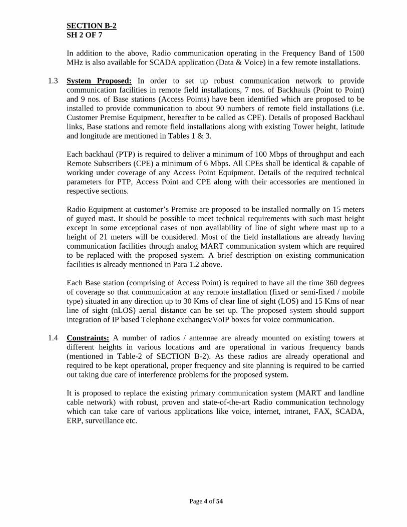
SECTION B-2 SH 2 OF 7 In addition to the above, Radio communication operating in the Frequency Band of 1500 MHz is also available for SCADA application (Data & Voice) in a few remote installations.
1.3 System Proposed: In order to set up robust communication network to provide communication facilities in remote field installations, 7 nos. of Backhauls (Point to Point) and 9 nos. of Base stations (Access Points) have been identified which are proposed to be installed to provide communication to about 90 numbers of remote field installations (i.e. Customer Premise Equipment, hereafter to be called as CPE). Details of proposed Backhaul links, Base stations and remote field installations along with existing Tower height, latitude and longitude are mentioned in Tables 1 & 3. Each backhaul (PTP) is required to deliver a minimum of 100 Mbps of throughput and each Remote Subscribers (CPE) a minimum of 6 Mbps. All CPEs shall be identical & capable of working under coverage of any Access Point Equipment. Details of the required technical parameters for PTP, Access Point and CPE along with their accessories are mentioned in respective sections. Radio Equipment at customer’s Premise are proposed to be installed normally on 15 meters of guyed mast. It should be possible to meet technical requirements with such mast height except in some exceptional cases of non availability of line of sight where mast up to a height of 21 meters will be considered. Most of the field installations are already having communication facilities through analog MART communication system which are required to be replaced with the proposed system. A brief description on existing communication facilities is already mentioned in Para 1.2 above. Each Base station (comprising of Access Point) is required to have all the time 360 degrees of coverage so that communication at any remote installation (fixed or semi-fixed / mobile type) situated in any direction up to 30 Kms of clear line of sight (LOS) and 15 Kms of near line of sight (nLOS) aerial distance can be set up. The proposed system should support integration of IP based Telephone exchanges/VoIP boxes for voice communication.
1.4 Constraints: A number of radios / antennae are already mounted on existing towers at
different heights in various locations and are operational in various frequency bands (mentioned in Table-2 of SECTION B-2). As these radios are already operational and required to be kept operational, proper frequency and site planning is required to be carried out taking due care of interference problems for the proposed system. It is proposed to replace the existing primary communication system (MART and landline cable network) with robust, proven and state-of-the-art Radio communication technology which can take care of various applications like voice, internet, intranet, FAX, SCADA, ERP, surveillance etc.
Page 5 of 54
SECTION B-2 SH 3 OF 7
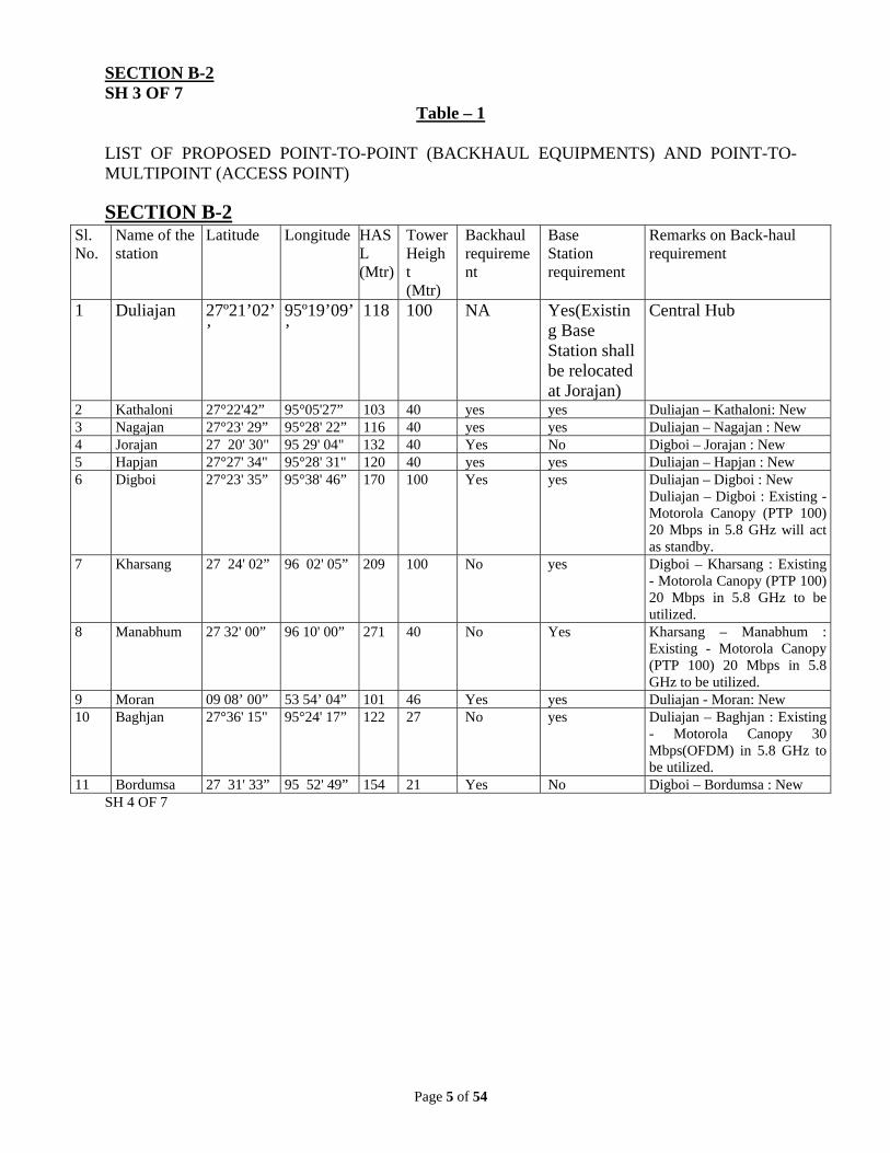
Table – 1 LIST OF PROPOSED POINT-TO-POINT (BACKHAUL EQUIPMENTS) AND POINT-TO-MULTIPOINT (ACCESS POINT)
SECTION B-2
SH 4 OF 7
Sl. No.
Name of the station
Latitude
Longitude
HASL (Mtr)
Tower Height (Mtr)
Backhaul requirement
Base Station requirement
Remarks on Back-haul requirement
1 Duliajan 27º21’02’’
95º19’09’’
118 100 NA Yes(Existing Base Station shall be relocated at Jorajan)
NOTES: 1.0 15 Sites are Mobile types but will be under coverage of above mentioned base stations.
Details will be given at the time of Installation. 2.0 Data mentioned above are based on our own Field survey. There may be slight
deviation. 3.0 There may be some changes in Fixed Remote installation site also depending on
existence of those sites at the time of installation. 4.0 Among the proposed towers, 15 Nos. shall be supplied and erected by the
successful bidder and the remaining shall be provided the OIL 5.0 Towers for mobile type installations (15 Nos.) shall be supplied and erected by
OIL. 6.0 Communication at remote installations to be set up with 15M of mast height.
Page 10 of 54
SECTION C SH 1 OF 4
1.0 SCOPE OF SUPPLY, WORKS AND SERVICES
(a) General
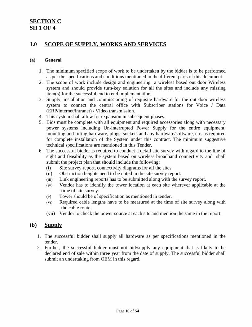
1. The minimum specified scope of work to be undertaken by the bidder is to be performed as per the specifications and conditions mentioned in the different parts of this document.
2. The scope of work include design and engineering a wireless based out door Wireless system and should provide turn-key solution for all the sites and include any missing item(s) for the successful end to end implementation.
3. Supply, installation and commissioning of requisite hardware for the out door wireless system to connect the central office with Subscriber stations for Voice / Data (ERP/internet/intranet) / Video transmission.
4. This system shall allow for expansion in subsequent phases. 5. Bids must be complete with all equipment and required accessories along with necessary
power systems including Un-interrupted Power Supply for the entire equipment, mounting and fitting hardware, plugs, sockets and any hardware/software, etc. as required for complete installation of the System under this contract. The minimum suggestive technical specifications are mentioned in this Tender.
6. The successful bidder is required to conduct a detail site survey with regard to the line of sight and feasibility as the system based on wireless broadband connectivity and shall submit the project plan that should include the following: (i) Site survey report, connectivity diagrams for all the sites. (ii) Obstruction heights need to be noted in the site survey report. (iii) Link engineering reports has to be submitted along with the survey report. (iv) Vendor has to identify the tower location at each site wherever applicable at the
time of site survey. (v) Tower should be of specification as mentioned in tender. (vi) Required cable lengths have to be measured at the time of site survey along with
the cable route. (vii) Vendor to check the power source at each site and mention the same in the report.
(b) Supply 1. The successful bidder shall supply all hardware as per specifications mentioned in the
tender. 2. Further, the successful bidder must not bid/supply any equipment that is likely to be
declared end of sale within three year from the date of supply. The successful bidder shall submit an undertaking from OEM in this regard.
Page 11 of 54
SECTION C SH 2 OF 4
3. The successful bidder shall be responsible for end-to-end implementation of connectivity
of all the locations under this tender and shall quote and provide/ supply any item(s) of latest make and model not included in the bill of materials, but required for successful implementation and commissioning of the system as well as its management. For such item(s), which have not been quoted by the successful bidder in the bid, but are required for successful completion of the project, the tenderer shall not pay for the same.
4. The successful bidder shall supply all the installation material/accessories/ consumables necessary for the installation of the systems and sub-systems.
5. The successful bidder shall provide patches and updates of Firmware free of cost during the warranty and AMC period.
(c) Installation, testing, commissioning & system integration
1. The scope of installation, commissioning & system integration shall mean to install, configure and integrate the following (but not limited to), adhering to essential security and safety measures.
2. Carry out installation of active components, passive components and accessories supplied as per standards for successful integration and implementation of the systems at all sites.
3. Configuring and fine-tuning of subsystems to achieve overall optimal network performance and highest security.
4. The components to be installed and configured shall include but not limited to: (i) Wireless equipment/network units (ii) Network Management System. (iii) All patches and updates shall be provided by the successful bidder during the
currency of the contract. (iv) Carrying out all general tests such as Power on test on delivery, pre-installation
checks to ensure correct connections, completeness of system documentation etc. (v) The successful bidder shall not cause any damage to buildings/other
premises/property, if any damage occurs, the successful bidder will perform restoration. Trenches, path/road cutting, etc. will be back-filled and restored to the original condition immediately after laying of the conduit/cable/erection of mast etc. The successful bidder if required shall also plug conduits and entrance holes with suitable sealing material, where the cable has been laid.
(vi) The system shall be subjected to inspection at various stages. The successful bidder shall follow all Safety Regulations and practices.
(vii) Bidders shall spell out various tests that are being proposed to be carried out for demonstrating the functionality of the solution.
Page 12 of 54
SECTION C SH 3 OF 4
(viii) The Successful Bidder shall provide warranty for all the components including
hardware, software, etc. as per Tender for a period of one year from the date of the issuance of Final Acceptance Certificate. Any delay for acceptance caused by the successful bidder will result in automatic extension of the total warranty period by the same period.
(ix) The bidder shall further quote the rates for the comprehensive AMC of the entire equipment including software supplied under this Tender for further Five years and shall be considered in the commercial evaluation.
(x) The successful bidder shall be responsible for the commissioning and maintenance of the entire system.
(d) Civil works
1. The requisite space shall be provided by Customer at all locations. 2. The successful bidder shall have to undertake the cabling, erection of Masts
supplied against this tender and their foundation works etc. as per the requirement. 3. Civil works including digging etc., if any, required for providing end to end
connectivity will be the responsibility of the successful bidder. 4. The successful bidder shall be responsible for restoring the areas to itsoriginal
shape wherever, the digging if any has been undertaken by him for end to end implementation of the system.
(e) Electrical works 1. Electrical cabling for the equipment and its accessories at each location shall be the
responsibility of the successful bidder. 2. Installation and configuration of the UPS and its accessories as per the standards
shall be the responsibility of the successful bidder. 3. The quantity of passive items if any shall be verified by the concerned official at
each site.
(f) Chemical Earthing
1. The successful bidder shall supply all materials required for Chemical Earthing at sites.
2. Installation & commissioning of Chemical Earthing as per Drawing and Specifications & Features mentioned in Annexure-7 of SECTION D-1 of Bid Document shall be within the scope of work of the successful bidder.
Page 13 of 54
SECTION C SH 4 OF 4
(g) Project Management
1. The successful bidder will undertake to completely manage and maintain the said equipment/infrastructure installed and commissioned at sites for a minimum period of Six years after the clearance of Final Acceptance. During the said period of undertaking, the successful bidder will be responsible for the smooth working of the total system installed at the locations under this project and to ensure minimum 99.5% uptime. This task of management of project will be termed as ‘Project Management’ in the rest of the document. Customer may extend the project management period for another four years.
2. Successful bidder shall depute engineer(s) and technician(s)/rigger(s) to operate, configure, maintain and manage the said connectivity during the Project Management period round the clock. They will be stationed at the office of the Customer. The successful bidder shall provide a mobile phone at his cost to each of this staff so that the customer can reach them for fault rectification and other related services in case of emergency beyond office hours.
(h) Training
The successful bidder shall provide basic training to OIL personnel on Installation, Operation and Maintenance of the supplied system at Duliajan. Advanced training on Hardware and Software aspects to 4 (four) numbers of OIL engineers in two batches (2 engineers per batch) is to be arranged at OEM’s place or their specified venue.
7.0 SYSTEM TO BE OFFERED
1.4 This procurement specification covers design, engineering, supply, packing, transportation from place of manufacture to site, installation, testing, integration with the existing LAN and Central EPABX system, startup, commissioning and performance testing of the Radio communication (5.8 GHz licence free ISM band) system for voice, data Intranet, Internet, SCADA, surveillance and ERP applications on Turn Key basis.
8.0 BILL OF MATERIALS FOR SUPPLY & SERVICES OF PROPOSED
COMMUNICATION NETWORK As detailed in SECTION E-1 of the ANNEXURE-1A.
Page 14 of 54
SECTION D-1 SH 1 OF 15
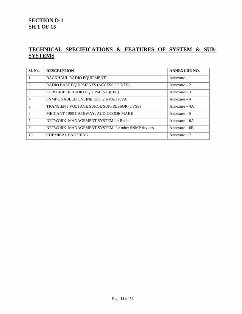
TECHNICAL SPECIFICATIONS & FEATURES OF SYSTEM & SUB-SYSTEMS
Sl. No. DESCRIPTION ANNEXURE NO.
1 BACKHAUL RADIO EQUIPMENT Annexure – 1
2 RADIO BASE EQUIPMENTS (ACCESS POINTS) Annexure – 2
5 TRANSIENT VOLTAGE SURGE SUPPRESSOR (TVSS) Annexure – 4A
6 MEDIANT-1000 GATEWAY, AUDIOCODE MAKE Annexure – 5
7 NETWORK MANAGEMENT SYSTEM for Radio Annexure – 6A
8 NETWORK MANAGEMENT SYSTEM for other SNMP devices Annexure – 6B
10 CHEMICAL EARTHING Annexure – 7
Page 15 of 54
SECTION D-1 SH 2 OF 15
Annexure - 1
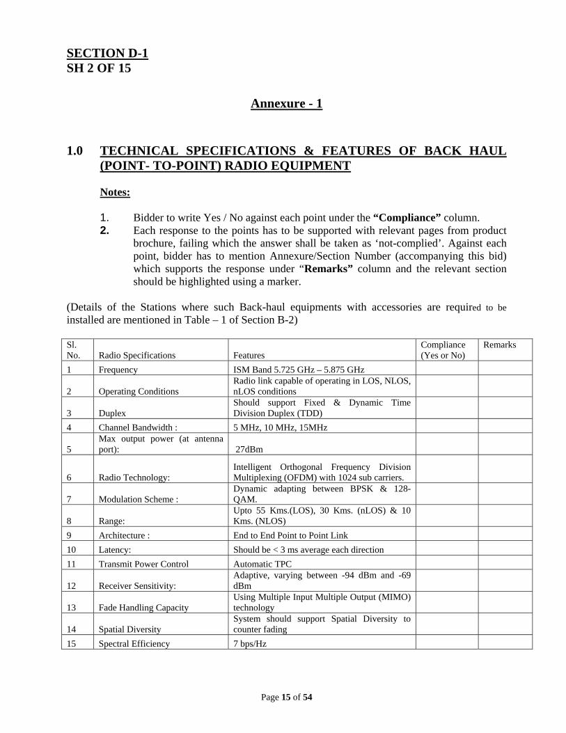
1.0 TECHNICAL SPECIFICATIONS & FEATURES OF BACK HAUL (POINT- TO-POINT) RADIO EQUIPMENT Notes: 1. Bidder to write Yes / No against each point under the “Compliance” column. 2. Each response to the points has to be supported with relevant pages from product
brochure, failing which the answer shall be taken as ‘not-complied’. Against each point, bidder has to mention Annexure/Section Number (accompanying this bid) which supports the response under “Remarks” column and the relevant section should be highlighted using a marker.
(Details of the Stations where such Back-haul equipments with accessories are required to be installed are mentioned in Table – 1 of Section B-2) Sl. No. Radio Specifications Features
Compliance (Yes or No)
Remarks
1 Frequency ISM Band 5.725 GHz – 5.875 GHz
2 Operating Conditions Radio link capable of operating in LOS, NLOS, nLOS conditions
3 Duplex Should support Fixed & Dynamic Time Division Duplex (TDD)
4 Channel Bandwidth : 5 MHz, 10 MHz, 15MHz
5 Max output power (at antenna port): 27dBm
6 Radio Technology: Intelligent Orthogonal Frequency Division Multiplexing (OFDM) with 1024 sub carriers.
7 Modulation Scheme : Dynamic adapting between BPSK & 128-QAM.
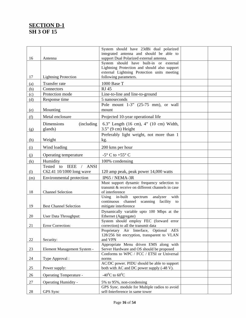
(h) Weight Preferably light weight, not more than 1 kg.
(i) Wind loading 200 kms per hour
(j) Operating temperature -5° C to +55° C
(k) Humidity 100% condensing
(l) Tested to IEEE / ANSI C62.41 10/1000 long wave 120 amp peak, peak power 14,000 watts
(m) Environmental protection IP65 / NEMA-3R
18 Channel Selection
Must support dynamic frequency selection to transmit & receive on different channels in case of interference
19 Best Channel Selection
Using in-built spectrum analyzer with continuous channel scanning facility to mitigate interference
20 User Data Throughput: Dynamically variable upto 100 Mbps at the Ethernet (Aggregate)
21 Error Correction: System should employ FEC (forward error correction) to all the transmit data
22 Security:
Proprietary Air Interface, Optional AES 128/256 bit encryption, transparent to VLAN and VPN
23 Element Management System - Appropriate Menu driven EMS along with Server Hardware and OS should be proposed
24 Type Approval : Conforms to WPC / FCC / ETSI or Universal norms
25 Power supply: AC/DC power. PIDU should be able to support both with AC and DC power supply (-48 V).
26 Operating Temperature - -400C to 600C
27 Operating Humidity - 5% to 95%, non-condensing
28 GPS Sync GPS Sync. module for Multiple radios to avoid self-Interference in same tower
Page 17 of 54
SECTION D-1 SH 4 OF 15
Annexure - 2
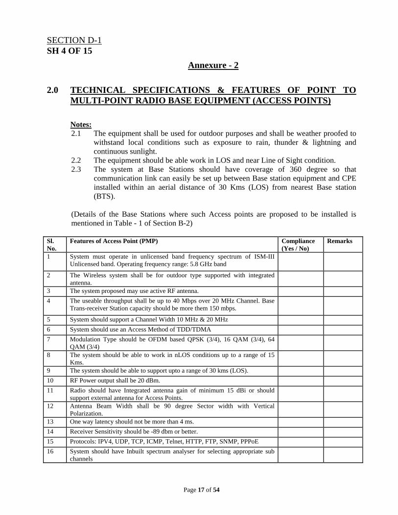
2.0 TECHNICAL SPECIFICATIONS & FEATURES OF POINT TO MULTI-POINT RADIO BASE EQUIPMENT (ACCESS POINTS)
Notes: 2.1 The equipment shall be used for outdoor purposes and shall be weather proofed to
withstand local conditions such as exposure to rain, thunder & lightning and continuous sunlight.
2.2 The equipment should be able work in LOS and near Line of Sight condition. 2.3 The system at Base Stations should have coverage of 360 degree so that
communication link can easily be set up between Base station equipment and CPE installed within an aerial distance of 30 Kms (LOS) from nearest Base station (BTS).
(Details of the Base Stations where such Access points are proposed to be installed is mentioned in Table - 1 of Section B-2)
Sl. No.
Features of Access Point (PMP) Compliance (Yes / No)
Remarks
1 System must operate in unlicensed band frequency spectrum of ISM-III Unlicensed band. Operating frequency range: 5.8 GHz band
2 The Wireless system shall be for outdoor type supported with integrated antenna.
3 The system proposed may use active RF antenna.
4 The useable throughput shall be up to 40 Mbps over 20 MHz Channel. Base Trans-receiver Station capacity should be more them 150 mbps.
5 System should support a Channel Width 10 MHz & 20 MHz
6 System should use an Access Method of TDD/TDMA
7 Modulation Type should be OFDM based QPSK (3/4), 16 QAM (3/4), 64 QAM (3/4)
8 The system should be able to work in nLOS conditions up to a range of 15 Kms.
9 The system should be able to support upto a range of 30 kms (LOS).
10 RF Power output shall be 20 dBm.
11 Radio should have Integrated antenna gain of minimum 15 dBi or should support external antenna for Access Points.
12 Antenna Beam Width shall be 90 degree Sector width with Vertical Polarization.
13 One way latency should not be more than 4 ms.
14 Receiver Sensitivity should be -89 dbm or better.
16 System should have Inbuilt spectrum analyser for selecting appropriate sub channels
Page 18 of 54
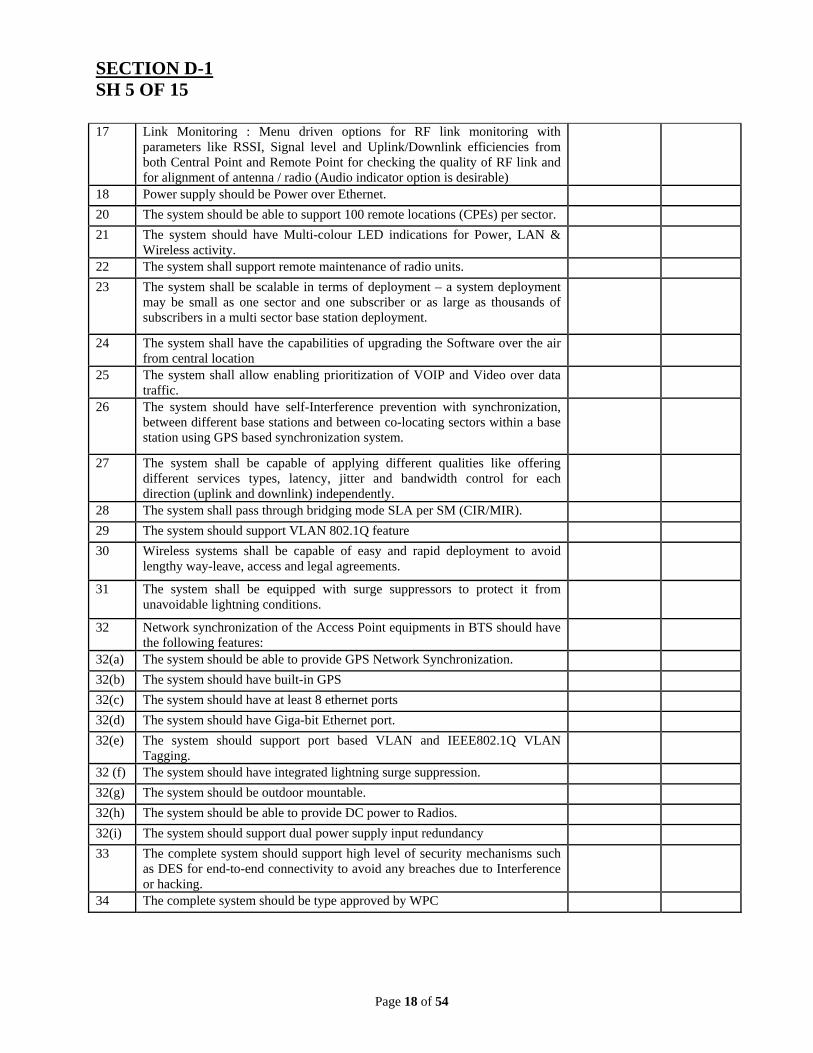
SECTION D-1 SH 5 OF 15 17 Link Monitoring : Menu driven options for RF link monitoring with
parameters like RSSI, Signal level and Uplink/Downlink efficiencies from both Central Point and Remote Point for checking the quality of RF link and for alignment of antenna / radio (Audio indicator option is desirable)
18 Power supply should be Power over Ethernet.
20 The system should be able to support 100 remote locations (CPEs) per sector.
21 The system should have Multi-colour LED indications for Power, LAN & Wireless activity.
22 The system shall support remote maintenance of radio units.
23 The system shall be scalable in terms of deployment – a system deployment may be small as one sector and one subscriber or as large as thousands of subscribers in a multi sector base station deployment.
24 The system shall have the capabilities of upgrading the Software over the air from central location
25 The system shall allow enabling prioritization of VOIP and Video over data traffic.
26 The system should have self-Interference prevention with synchronization, between different base stations and between co-locating sectors within a base station using GPS based synchronization system.
27 The system shall be capable of applying different qualities like offering different services types, latency, jitter and bandwidth control for each direction (uplink and downlink) independently.
28 The system shall pass through bridging mode SLA per SM (CIR/MIR).
29 The system should support VLAN 802.1Q feature
30 Wireless systems shall be capable of easy and rapid deployment to avoid lengthy way-leave, access and legal agreements.
31 The system shall be equipped with surge suppressors to protect it from unavoidable lightning conditions.
32 Network synchronization of the Access Point equipments in BTS should have the following features:
32(a) The system should be able to provide GPS Network Synchronization.
32(b) The system should have built-in GPS
32(c) The system should have at least 8 ethernet ports
32(d) The system should have Giga-bit Ethernet port.
32(e) The system should support port based VLAN and IEEE802.1Q VLAN Tagging.
32 (f) The system should have integrated lightning surge suppression.
32(g) The system should be outdoor mountable.
32(h) The system should be able to provide DC power to Radios.
32(i) The system should support dual power supply input redundancy
33 The complete system should support high level of security mechanisms such as DES for end-to-end connectivity to avoid any breaches due to Interference or hacking.
34 The complete system should be type approved by WPC
Page 19 of 54
SECTION D-1 SH 6 OF 15
Annexure – 3
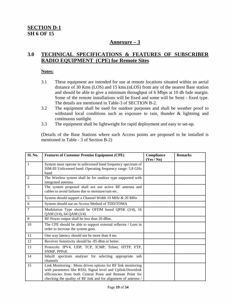
3.0 TECHNICAL SPECIFICATIONS & FEATURES OF SUBSCRIBER RADIO EQUIPMENT (CPE) for Remote Sites
Notes:
3.1 These equipment are intended for use at remote locations situated within an aerial
distance of 30 Kms (LOS) and 15 kms.(nLOS) from any of the nearest Base station and should be able to give a minimum throughput of 6 Mbps at 10 db fade margin. Some of the remote installations will be fixed and some will be Semi - fixed type. The details are mentioned in Table-3 of SECTION B-2.
3.2 The equipment shall be used for outdoor purposes and shall be weather proof to withstand local conditions such as exposure to rain, thunder & lightning and continuous sunlight.
3.3 The equipment shall be lightweight for rapid deployment and easy to set-up.
(Details of the Base Stations where such Access points are proposed to be installed is mentioned in Table - 3 of Section B-2)
Sl. No. Features of Customer Premise Equipment (CPE) Compliance
(Yes / No) Remarks
1 System must operate in unlicensed band frequency spectrum of ISM-III Unlicensed band. Operating frequency range: 5.8 GHz band
2 The Wireless system shall be for outdoor type supported with integrated antenna.
3 The system proposed shall not use active RF antenna and cables to avoid failures due to moisture/rain etc.
5 System should support a Channel Width 10 MHz & 20 MHz
6 System should use an Access Method of TDD/TDMA
7 Modulation Type should be OFDM based QPSK (3/4), 16 QAM (3/4), 64 QAM (3/4)
8 RF Power output shall be less than 20 dBm.
10 The CPE should be able to support external reflector / Lens in order to increase the system gain.
11 One way latency should not be more than 4 ms.
12 Receiver Sensitivity should be -85 dbm or better.
14 Inbuilt spectrum analyser for selecting appropriate sub channels
15 Link Monitoring : Menu driven options for RF link monitoring with parameters like RSSI, Signal level and Uplink/Downlink efficiencies from both Central Point and Remote Point for checking the quality of RF link and for alignment of antenna /
Page 20 of 54
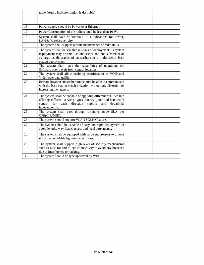
radio (Audio indicator option is desirable)
16 Power supply should be Power over Ethernet.
17 Power Consumption of the radio should be less than 10 W.
18 System shall have Multicolour LED indications for Power, LAN & Wireless activity.
19 The system shall support remote maintenance of radio units.
20 The system shall be scalable in terms of deployment – a system deployment may be small as one sector and one subscriber or as large as thousands of subscribers in a multi sector base station deployment.
21 The system shall have the capabilities of upgrading the Software over the air from central location
22 The system shall allow enabling prioritization of VOIP and Video over data traffic.
23 Remote location subscriber unit should be able to communicate with the base station synchronization without any distortion or increasing the latency.
24 The system shall be capable of applying different qualities like offering different services types, latency, jitter and bandwidth control for each direction (uplink and downlink) independently.
25 The system shall pass through bridging mode SLA per CPE(CIR/MIR).
26 The system should support VLAN 802.1Q feature.
27 The systems shall be capable of easy and rapid deployment to avoid lengthy way-leave, access and legal agreements.
28 The system shall be equipped with surge suppressors to protect it from unavoidable lightning conditions.
29 The system shall support high level of security mechanisms such as DES for end-to-end connectivity to avoid any breaches due to Interference or hacking.
30 The system should be type approved by WPC
Page 21 of 54
SECTION D-1 SH 8 OF 15
Annexure – 4
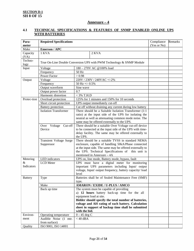
4.1 TECHNICAL SPECIFICATIONS & FEATURES OF SNMP ENABLED ONLINE UPS WITH BATTERIES
Input Voltage 180 – 270V AC @100% load Frequency 50 Hz Power Factor > 0.98
Output Voltage 220V / 230V / 240VAC +/-2% Frequency 50 Hz +/- 0.5% Output waveform Sine wave Output power factor 0.7 Harmonic distortion < 3% T.H.D
Protec-tion Overload protection 125% for 1 minutes and 150% for 10 seconds Short circuit protection UPS output immediately cut-off Battery protection Cut off without draining any current during low battery Isolation Transformer There should be a Suitable Isolation Transformer (1:1
ratio) at the input side of the UPS for isolating the neutral as well as attenuating common mode noise. The same may be offered externally to the UPS.
Over Voltage Cut-off Device
There should be a suitable Over Voltage cut-off device to be connected at the input side of the UPS with time-delay facility. The same may be offered externally to the UPS.
Transient Voltage Surge Suppressor
There should be a suitable TVSS in standard NEMA enclosure, capable of handling 50kA/Phase connected at the input side. The same may be offered externally to the UPS. Technical Specifications of this unit is mentioned in Annexure – 4A
Metering & Indicators
LED indicators UPS on, line mode, Battery mode, bypass, fault LCD Meter UPS must have a digital meter for monitoring
important UPS parameters including Input/ output voltage, Input/ output frequency, battery capacity/ load level
Battery Type Batteries shall be of Sealed Maintenance Free (SMF) type.
Make AMARON / EXIDE / U-PLUS / AMCO Back up time The system must be capable of providing
a) 12 hours battery back-up time for the all equipment load at site. Bidder should specify the total number of batteries, voltage and AH rating of each battery. Calculation sheet in support of backup time shall be submitted with the bid.
Environ-ment
Operating temperature 0 – 45 deg C Audible Noise (1 mtr. from surface)
< 40 dBA
Quality ISO 9001, ISO 14001
Page 22 of 54
SECTION D-1 SH 9 OF 15
Annexure – 4A
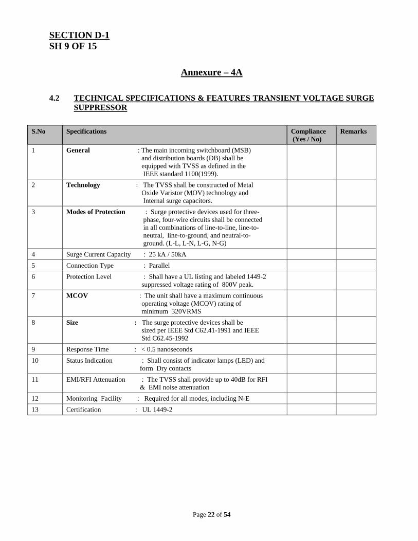
4.2 TECHNICAL SPECIFICATIONS & FEATURES TRANSIENT VOLTAGE SURGE
SUPPRESSOR
S.No Specifications
Compliance (Yes / No)
Remarks
1 General : The main incoming switchboard (MSB) and distribution boards (DB) shall be equipped with TVSS as defined in the IEEE standard 1100(1999).
2 Technology : The TVSS shall be constructed of Metal Oxide Varistor (MOV) technology and Internal surge capacitors.
3 Modes of Protection : Surge protective devices used for three- phase, four-wire circuits shall be connected in all combinations of line-to-line, line-to- neutral, line-to-ground, and neutral-to- ground. (L-L, L-N, L-G, N-G)
4 Surge Current Capacity : 25 kA / 50kA
5 Connection Type : Parallel
6 Protection Level : Shall have a UL listing and labeled 1449-2 suppressed voltage rating of 800V peak.
7 MCOV : The unit shall have a maximum continuous operating voltage (MCOV) rating of minimum 320VRMS
8 Size : The surge protective devices shall be sized per IEEE Std C62.41-1991 and IEEE Std C62.45-1992
9 Response Time : < 0.5 nanoseconds
10 Status Indication : Shall consist of indicator lamps (LED) and form Dry contacts
11 EMI/RFI Attenuation : The TVSS shall provide up to 40dB for RFI & EMI noise attenuation
12 Monitoring Facility : Required for all modes, including N-E
13 Certification : UL 1449-2
Page 23 of 54
SECTION D-1 SH 10 OF 15
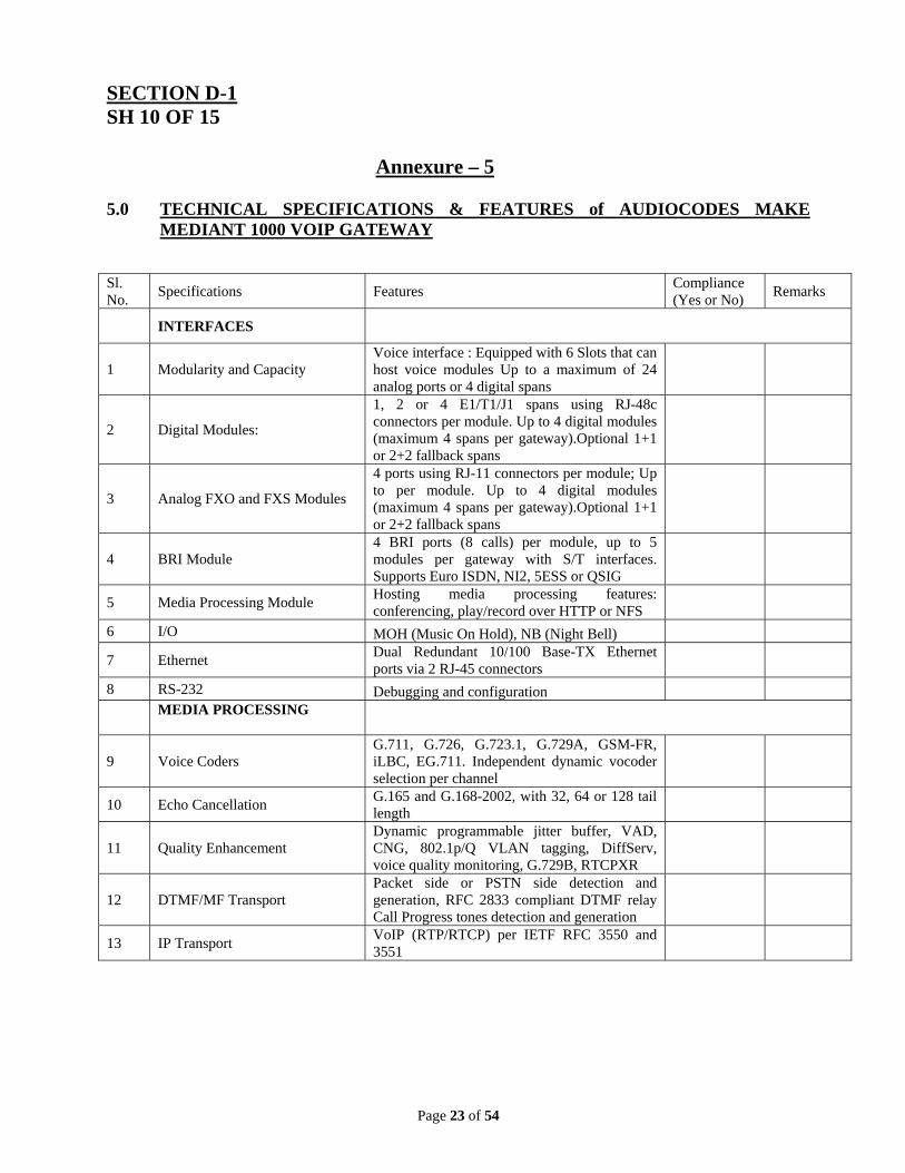
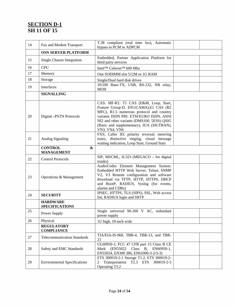
Annexure – 5 5.0 TECHNICAL SPECIFICATIONS & FEATURES of AUDIOCODES MAKE
MEDIANT 1000 VOIP GATEWAY
Sl. No.
Specifications Features Compliance (Yes or No)
Remarks
INTERFACES
1 Modularity and Capacity Voice interface : Equipped with 6 Slots that can host voice modules Up to a maximum of 24 analog ports or 4 digital spans
2 Digital Modules:
1, 2 or 4 E1/T1/J1 spans using RJ-48c connectors per module. Up to 4 digital modules (maximum 4 spans per gateway).Optional 1+1 or 2+2 fallback spans
3 Analog FXO and FXS Modules
4 ports using RJ-11 connectors per module; Up to per module. Up to 4 digital modules (maximum 4 spans per gateway).Optional 1+1 or 2+2 fallback spans
4 BRI Module 4 BRI ports (8 calls) per module, up to 5 modules per gateway with S/T interfaces. Supports Euro ISDN, NI2, 5ESS or QSIG
5 Media Processing Module Hosting media processing features: conferencing, play/record over HTTP or NFS
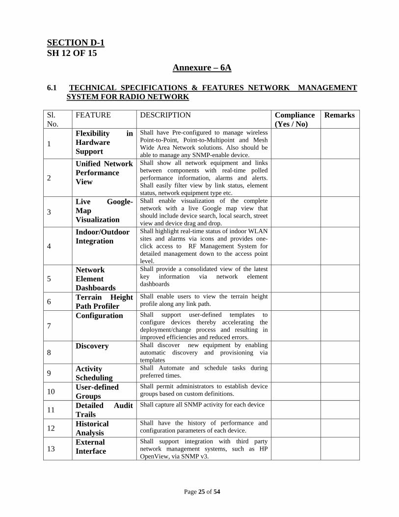
Annexure – 6A 6.1 TECHNICAL SPECIFICATIONS & FEATURES NETWORK MANAGEMENT
SYSTEM FOR RADIO NETWORK Sl. No.
FEATURE DESCRIPTION Compliance (Yes / No)
Remarks
1 Flexibility in Hardware Support
Shall have Pre-configured to manage wireless Point-to-Point, Point-to-Multipoint and Mesh Wide Area Network solutions. Also should be able to manage any SNMP-enable device.
2
Unified Network Performance View
Shall show all network equipment and links between components with real-time polled performance information, alarms and alerts. Shall easily filter view by link status, element status, network equipment type etc.
3 Live Google-Map Visualization
Shall enable visualization of the complete network with a live Google map view that should include device search, local search, street view and device drag and drop.
4
Indoor/Outdoor Integration
Shall highlight real-time status of indoor WLAN sites and alarms via icons and provides one-click access to RF Management System for detailed management down to the access point level.
5 Network Element Dashboards
Shall provide a consolidated view of the latest key information via network element dashboards
6 Terrain Height Path Profiler
Shall enable users to view the terrain height profile along any link path.
7 Configuration Shall support user-defined templates to
configure devices thereby accelerating the deployment/change process and resulting in improved efficiencies and reduced errors.
8 Discovery Shall discover new equipment by enabling
automatic discovery and provisioning via templates
9 Activity Scheduling
Shall Automate and schedule tasks during preferred times.
10 User-defined Groups
Shall permit administrators to establish device groups based on custom definitions.
11 Detailed Audit Trails
Shall capture all SNMP activity for each device
12 Historical Analysis
Shall have the history of performance and configuration parameters of each device.
13 External Interface
Shall support integration with third party network management systems, such as HP OpenView, via SNMP v3.
Page 26 of 54
SECTION D-1 SH 13 OF 15
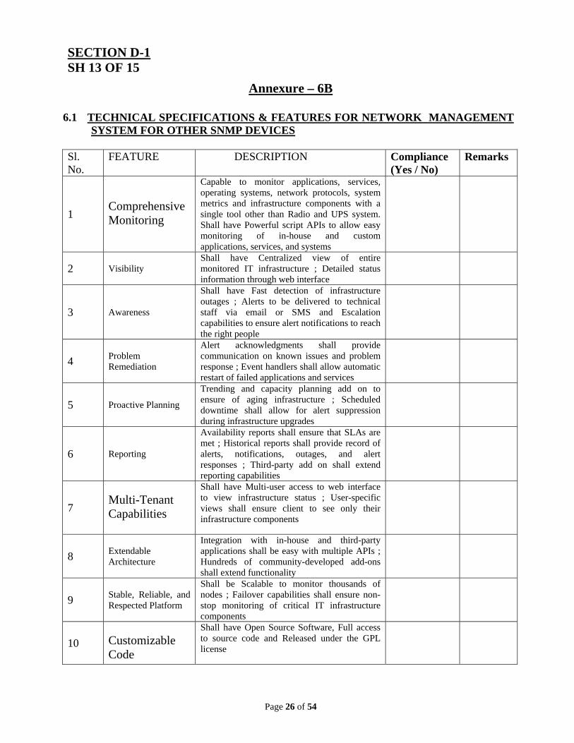
Annexure – 6B
6.1 TECHNICAL SPECIFICATIONS & FEATURES FOR NETWORK MANAGEMENT SYSTEM FOR OTHER SNMP DEVICES
Sl. No.
FEATURE DESCRIPTION Compliance (Yes / No)
Remarks
1 Comprehensive Monitoring
Capable to monitor applications, services, operating systems, network protocols, system metrics and infrastructure components with a single tool other than Radio and UPS system. Shall have Powerful script APIs to allow easy monitoring of in-house and custom applications, services, and systems
2 Visibility Shall have Centralized view of entire monitored IT infrastructure ; Detailed status information through web interface
3 Awareness
Shall have Fast detection of infrastructure outages ; Alerts to be delivered to technical staff via email or SMS and Escalation capabilities to ensure alert notifications to reach the right people
4 Problem Remediation
Alert acknowledgments shall provide communication on known issues and problem response ; Event handlers shall allow automatic restart of failed applications and services
5 Proactive Planning
Trending and capacity planning add on to ensure of aging infrastructure ; Scheduled downtime shall allow for alert suppression during infrastructure upgrades
6 Reporting
Availability reports shall ensure that SLAs are met ; Historical reports shall provide record of alerts, notifications, outages, and alert responses ; Third-party add on shall extend reporting capabilities
7 Multi-Tenant Capabilities
Shall have Multi-user access to web interface to view infrastructure status ; User-specific views shall ensure client to see only their infrastructure components
8 Extendable Architecture
Integration with in-house and third-party applications shall be easy with multiple APIs ; Hundreds of community-developed add-ons shall extend functionality
9 Stable, Reliable, and Respected Platform
Shall be Scalable to monitor thousands of nodes ; Failover capabilities shall ensure non-stop monitoring of critical IT infrastructure components
10 Customizable Code
Shall have Open Source Software, Full access to source code and Released under the GPL license
Page 27 of 54
SECTION D-1 SH 14 OF 15
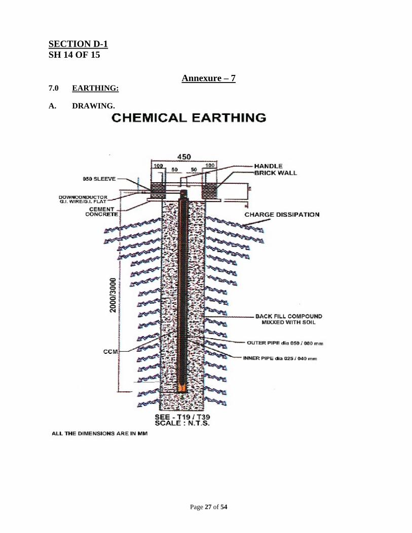
Annexure – 7 7.0 EARTHING: A. DRAWING.
Page 28 of 54
SECTION D-1 SH 15 OF 15
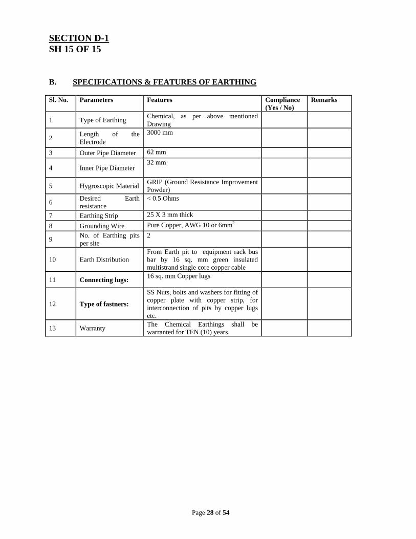
B. SPECIFICATIONS & FEATURES OF EARTHING Sl. No. Parameters Features Compliance
(Yes / No) Remarks
1 Type of Earthing Chemical, as per above mentioned Drawing
2 Length of the Electrode
3000 mm
3 Outer Pipe Diameter 62 mm
4 Inner Pipe Diameter 32 mm
5 Hygroscopic Material GRIP (Ground Resistance Improvement Powder)
6 Desired Earth resistance
< 0.5 Ohms
7 Earthing Strip 25 X 3 mm thick
8 Grounding Wire Pure Copper, AWG 10 or 6mm2
9 No. of Earthing pits per site
2
10 Earth Distribution From Earth pit to equipment rack bus bar by 16 sq. mm green insulated multistrand single core copper cable
11 Connecting lugs: 16 sq. mm Copper lugs
12 Type of fastners:
SS Nuts, bolts and washers for fitting of copper plate with copper strip, for interconnection of pits by copper lugs etc.
13 Warranty The Chemical Earthings shall be warranted for TEN (10) years.
Page 29 of 54
SECTION D-2 SH 1 OF 8
SPECIAL CONDITIONS :
1.1 Standards of the works :
The works shall be in accordance with the details in the BID document. To the extent that the standard of the works has not been specified in the BID document, the successful Bidder shall use good quality materials, techniques and standards and execute the works with care, skill and diligence required in accordance with best practice.
1.2 SPARES
The successful Bidder shall maintain spares or replacement parts for a period of Six (06) years from the completion certificate date. Such spares or replacement parts should be fully compatible with similar items supplied against this tender. The bidder shall submit a certificate from OEM confirming spares and technical support for at least 6 years.
1.3 SOFTWARE Unless otherwise stated in the bid document, the successful Bidder shall be responsible
for providing all latest software and associated documentation necessary for the satisfactory operation of the equipment. The successful Bidder shall also provide free of cost any software upgrades which the OEM shall make available during warranty and AMC period. Any software upgrades in future shall not necessitate replacement of hardwares supplied against this tender.
1.4 QUALITY ASSURANCE
The Bidder will submit a detailed procedure for Quality Assurance alongwith his Bid. The Bid shall be considered incomplete in the absence of Quality Assurance procedure. The Quality Assurance procedure should indicate the organizational approach for Quality Control & Quality Assurance of the job.
1.5 DOCUMENTATION
Successful Bidder shall furnish 3 (Three) sets each of Hard & Soft copies consisting of the RF design engineering, manuals for each equipment, layout drawings of each site, fault diagnostics details necessary to test, maintain and support the system and sub-systems including operating software.
Page 30 of 54
SECTION D-2 SH 2 OF 8 1.6 TESTS
The Tests concern all the equipment, systems and sub-systems supplied against this tender.
1.7 FIELD ACCEPTANCE TEST
Once the system is installed and operating, it shall be tested by the successful bidder and witnessed by OIL ENGINEER. The Test shall be carried out as per the detailed test procedure supplied by Bidder and approved by the OIL ENGINEER. Once the Tests successfully performed, the temporary acceptance of the system will be given. Only then the system will be ready for “Test Run”.
1.8 TEST RUN 1.8.1 This Test aims at keeping the complete system in operation for a period of 10 days
continuously. In case of failure, the Tests will be re-started till the system operates without failure for 10 days continuously. OIL ENGINEER shall have the right to reject the complete system or part thereof in the event(s) of the acceptance Tests failing in two attempts. The “Test Run” shall be carried out after the commissioning of complete system.
1.8.2 Various observations and test results obtained during the various tests shall be
documented and produced in the form of a report by the Bidder.
1.8.3 If malfunctions or failure of a unit or sub-system repeat, the Test shall be terminated and Bidder shall replace the necessary components and assemblies to correct the deficiencies. Thereafter, the Test shall commence all over again from the start as mentioned above. If after this one replacement, the unit or sub-system still fails to meet the specifications, the Bidder shall replace the complete unit or sub-system with the one that meets the requirements, and restart the Test all over again.
All cost for repair/replacement of defective unit/ component/system/sub-system shall be to Bidder’s account.
Page 31 of 54
SECTION D-2
SH 3 OF 8
1.9 INSTALLATION AND COMMISSIONING
1.9.1 The whole project is required to be completed on Turn- Key basis. Accordingly, Bidder is understood to have assessed and quoted for all the items required for successful completion of the Project. It will be the responsibility of the Bidder to provide such items on free of cost basis which are not quoted in the bid but otherwise required at the time of installation for completion and successful commissioning of the project.
1.9.2 The successful Bidder shall offer the services of an installation Team which shall be responsible to install and commission the entire system. The whole project including frequency & RF planning, etc. will be carried out directly under the supervision of OEM’s technical team.
1.9.3 The successful Bidder shall ensure that installation of new system shall not affect the
operation of the existing system already installed. In case interference of frequency is observed affecting the existing system, the Bidder has to provide additional equipment which will mitigate interference problem at his own cost.
1.9.4 Successful Bidder shall bring all installation aids and test equipment in order to carry
out the job successfully. A list of the same is to be submitted to the OIL ENGINEER for the review.
1.9.5 Successful Bidder shall take / assist OIL for obtaining all necessary clearances from
Statutory bodies like Department of Telecom (DOT), WPC, SACFA etc, wherever applicable for setting up communication network under this project.
1.9.6 Installation & Commissioning shall also be governed by relevant clauses as mentioned
in SECTION C of the Bid Document. 1.9.7 Installation & Commissioning shall be treated as complete after installation of all the
systems and sub-systems at all sites and successful completion of ‘Test Run’. 1.9.8 Payment towards Installation & Commissioning shall be released after completion as
per para 1.9.7 above. Installation & Commissioning charges as quoted by Bidder shall be inclusive of to and fro expenditure, food & lodging at sites and applicable Service Tax / Income Tax (if any). However, OIL will provide vehicle to attend Installation & commissioning jobs.
1.9.9 The successful bidder shall set up a project office headed by a Project
Manager at Duliajan during the entire period of installation & commissioning phase.
Page 32 of 54
SECTION D-2 SH 4 OF 8
1.10 WARRANTY
1.10.1 The Successful Bidder shall warrant that all equipment are manufactured with highest
quality of materials. The equipment supplied and installed, software, documentation and workmanship are of the highest grade and consistent with the established and general standards for the application area and is in full conformity with the specifications given in the BID document. If any part or component or sub-system is found to be defective, the same shall be replaced free of all costs to the COMPANY (OIL). The decision of the COMPANY or OIL ENGINEER in deciding defective component or part or sub-system shall be final.
1.10.2 The system shall be warranted to give the specified performance for a period of
Twelve months from the date of issue of COMPLETION CERTIFICATE by the COMPANY. In case any part or component or sub-system or equipment (Hardware & Software) is found to be defective and is replaced/ modified in accordance with clause 1.10.1 above, the item shall be warranted till the complete warranty period of the system/ sub-system. All maintenance work, components, spare parts etc. during the warranty period shall be at the cost of Bidder.
1.11 ANNUAL MAINTENANCE CONTRACT (AMC) 1.11.1 The Communication system being supplied, installed and commissioned is required to
be maintained for 5 (Five) years after warranty period. The system is required to be fully operational round the clock. The bidder must quote for providing post warranty maintenance service through Onsite Comprehensive Annual Maintenance Contract (AMC) for a period of Five (05) years. This AMC shall be applicable to all items, hardware and softwares, mentioned in Schedule of Prices of SECTION E-1, except Item Sl. Nos. 1b,1c, 2b, 2c, 3c, 3d, 4b, 5b, 6k, 6l, 6m, 6n, 7a, 7b, 7c, 7d & 7e.
1.11.2 Supplier shall post OEM Certified service engineer(s) along with Riggers at Duliajan permanently for the entire warranty & AMC period. The service engineer(s) so posted shall be qualified and fully conversant with the operation and maintenance aspect of the complete system and sub-systems of other vendors (e.g. UPS, VoIP, switches, routers etc.) supplied against this tender/purchase order. The riggers should be competent enough to work on towers upto a height of 100 Meter to carry out installation/maintenance of Radios, antennae, cables and other accessories.
Page 33 of 54
SECTION D-2 SH 5 OF 8 1.11.3 The service engineer shall be required to check the health of the system on daily basis.
Any defect or breakdown observed or reported by OIL shall be attended immediately. Periodic preventive maintenance shall be done by the service engineer as per the maintenance schedule recommended by the manufacturers (OEMs) and report to be submitted to OIL. Format of such periodic preventive maintenance schedules of all systems and sub-systems as recommended by OEMs should be enclosed along with the offer.
1.11.4 Supplier shall maintain minimum vital spares at site (Duliajan) to restore the system
immediately in case of breakdown during warranty and AMC period. List of vital spares to be maintained at site should be provided along with the bid.
1.11.5 Most of the sites (Production installations) where communication systems are
proposed to be installed are fixed type and permanent in nature. There will be a few sites (Drilling & work-over) which are semi-permanent type where communication system is required to be operational for a period of around 2 weeks to 6 months.
1.11.6 During warranty and AMC period, the service engineer(s) and riggers posted at
Duliajan shall be required to redeploy the communication equipment from one site to another as per the instructions of OIL engineers for semi-permanent type of sites. However, erection and dismantling of communication towers will be under the scope of OIL work. Transport for such redeployment activity will also be provided by OIL.
1.11.7 Any breakdown of the system or part of the system shall be attended immediately and
resolved within a period of 24 hours for major equipment failure and 48 hours for minor equipment failure. Systems related to Back-haul & Base stations equipment including accessories will be treated as major equipment and equipment installed at customer premises as minor equipment.
1.11.8 In case of non fulfillment of obligations as mentioned in para 1.11.7, penalty @ Rs.
200/- per day per equipment for minor failure, @ Rs. 1000/- per day for major failure and @ 1/2% of AMC value per week for failure of complete system will be imposed and deducted while making payment of AMC.
1.11.9 The payment for AMC shall be released Half Yearly after providing satisfactory
services.
1.11.10 The charge quoted for Annual Maintenance Contract (AMC) shall be fixed and firm.
Page 34 of 54
SECTION D-2 SH 6 OF 8
5 years of AMC charges as mentioned in Clause 1.11.10 shall be considered for evaluation of the bid.
1.12 DELIVERY SCHEDULE 1.12.1 Time is the essence of this project. The project is required to be
completed within 8 (Eight) months from date of issue of Purchase Order / Letter of Intent.
1.12.2 Bidder must submit bar chart showing separately delivery of equipment and carrying out of all services to complete the project within specified time. 1.12.3 The successful bidder must submit monthly progress report during execution of the project.
1.13 TRAINING Basic training to OIL personnel is required to be provided by the supplier on Installation, Operation and Maintenance of the supplied system at Duliajan. Advanced training on Hardware and Software aspects to 4 (four) numbers of OIL engineers in two batches (2 engineers per batch) is to be arranged at OEM’s place or venue specified by them. Bidder should quote for such training indicating the venue and duration per batch for such training. Cost of Travel, board & lodging will be arranged & borne by the company (OIL). Supplier must send intimation of such training at least three months prior to commencement of training programme.
1.14 BIDDER TO OBTAIN OWN INFORMATION 1.14.1 In their own interest, BIDDERS are advised to visit the sites, prior to submission of
BIDS to acquaint themselves with the site conditions, availability of space at various locations, existing as well as proposed installations, Towers / masts, frequencies in use, site data, availability of facilities etc. at their own cost.
1.14.2 During such visit, BIDDERS may interact with the user department and obtain
information regarding existing equipment and exact requirement of proposed system. 1.14.3 After the visit, BIDDERS are understood to have known all the constraints and
requirements of this Project which will facilitate them to quote for all the items.
Page 35 of 54
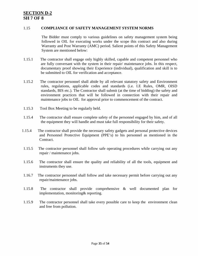
SECTION D-2 SH 7 OF 8 1.15 COMPLIANCE OF SAFETY MANAGEMENT SYSTEM NORMS
The Bidder must comply to various guidelines on safety management system being followed in OIL for executing works under the scope this contract and also during Warranty and Post Warranty (AMC) period. Salient points of this Safety Management System are mentioned below:
1.15.1 The contractor shall engage only highly skilled, capable and competent personnel who are fully conversant with the system in their repair/ maintenance jobs. In this respect, documentary proof showing their Experience (individual), qualification and skill is to be submitted to OIL for verification and acceptance.
1.15.2 The contractor personnel shall abide by all relevant statutory safety and Environment rules, regulations, applicable codes and standards (i.e. I.E Rules, OMR, OISD standards, BIS etc.). The Contractor shall submit (at the time of bidding) the safety and environment practices that will be followed in connection with their repair and maintenance jobs to OIL for approval prior to commencement of the contract.
1.15.3 Tool Box Meeting to be regularly held.
1.15.4 The contractor shall ensure complete safety of the personnel engaged by him, and of all the equipment they will handle and must take full responsibility for their safety.
1.15.4 The contractor shall provide the necessary safety gadgets and personal protective devices
and Personnel Protective Equipment (PPE’s) to his personnel as mentioned in the Contract.
1.15.5 The contractor personnel shall follow safe operating procedures while carrying out any
repair / maintenance jobs.
1.15.6 The contractor shall ensure the quality and reliability of all the tools, equipment and instruments they use.
1.16.7 The contractor personnel shall follow and take necessary permit before carrying out any
repair/maintenance jobs.
1.15.8 The contractor shall provide comprehensive & well documented plan for implementation, monitoring& reporting.
1.15.9 The contractor personnel shall take every possible care to keep the environment clean
and free from pollution.
Page 36 of 54
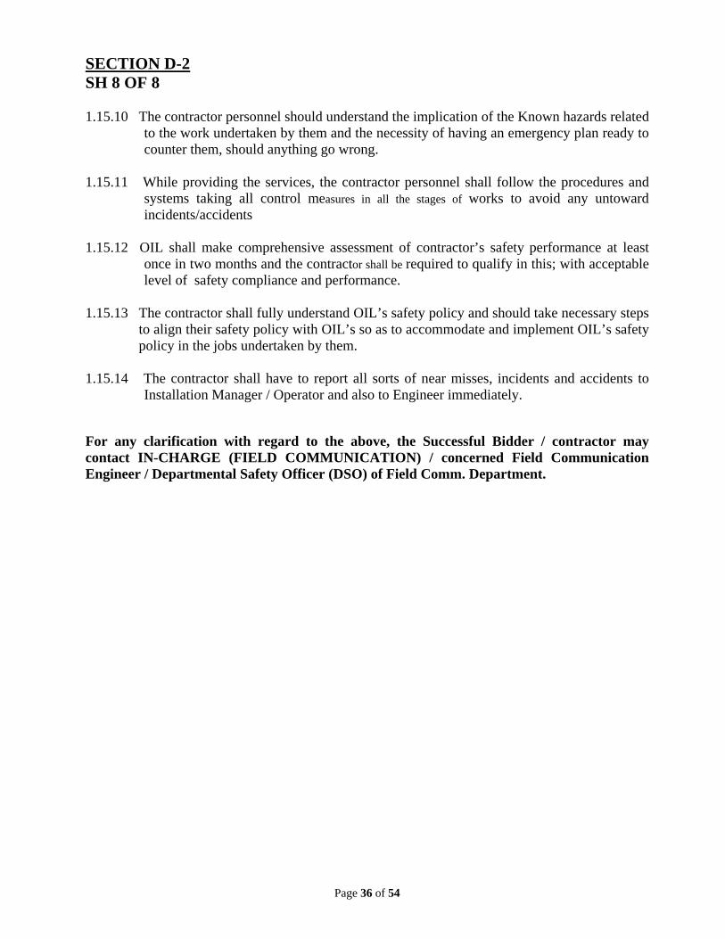
SECTION D-2 SH 8 OF 8 1.15.10 The contractor personnel should understand the implication of the Known hazards related
to the work undertaken by them and the necessity of having an emergency plan ready to counter them, should anything go wrong.
1.15.11 While providing the services, the contractor personnel shall follow the procedures and
systems taking all control measures in all the stages of works to avoid any untoward incidents/accidents
1.15.12 OIL shall make comprehensive assessment of contractor’s safety performance at least
once in two months and the contractor shall be required to qualify in this; with acceptable level of safety compliance and performance.
1.15.13 The contractor shall fully understand OIL’s safety policy and should take necessary steps to align their safety policy with OIL’s so as to accommodate and implement OIL’s safety policy in the jobs undertaken by them.
1.15.14 The contractor shall have to report all sorts of near misses, incidents and accidents to
Installation Manager / Operator and also to Engineer immediately.
For any clarification with regard to the above, the Successful Bidder / contractor may contact IN-CHARGE (FIELD COMMUNICATION) / concerned Field Communication Engineer / Departmental Safety Officer (DSO) of Field Comm. Department.
Page 37 of 54
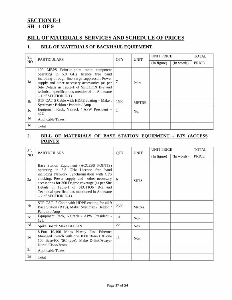
SECTION E-1 SH 1 OF 9 BILL OF MATERIALS, SERVICES AND SCHEDULE OF PRICES
1. BILL OF MATERIALS OF BACKHAUL EQUIPMENT
SL NO
PARTICULARS QTY UNIT UNIT PRICE TOTAL
PRICE (In figure) (In words)
1a
100 MBPS Point-to-point radio equipment operating in 5.8 GHz licence free band including through line surge suppressor, Power supply and other necessary accessories (as per Site Details in Table-1 of SECTION B-2 and technical specifications mentioned in Annexure – 1 of SECTION D-1)
7 Pairs
1b STP CAT 5 Cable with HDPE coating – Make : Systimax / Beldon / Panduit / Amp
1500 METRE
1c Equipment Rack, Valrack / APW President – 42U
1 No.
1d Applicable Taxes
1e Total
2. BILL OF MATERIALS OF BASE STATION EQUIPMENT - BTS (ACCESS POINTS)
SL NO
PARTICULARS QTY UNIT UNIT PRICE TOTAL
PRICE (In figure) (In words)
2a
Base Station Equipment (ACCESS POINTS) operating in 5.8 GHz Licence free band including Network Synchronisation with GPS clocking, Power supply and other necessary accessories for 360 Degree coverage (as per Site Details in Table-1 of SECTION B-2 and Technical specifications mentioned in Annexure – 2 of SECTION D-1)
9 SETS
2b STP CAT- 5 Cable with HDPE coating for all 9 Base Station (BTS), Make: Systimax / Beldon / Panduit / Amp
2500 Metres
2c Equipment Rack, Valrack / APW President - 12U
10 Nos.
2d Spike Board, Make BELKIN 22 Nos.
2e
8-Port 10/100 Mbps N-way Fast Ethernet Managed Switch with one 1000 Base-T & one 100 Base-FX (SC type); Make D-link/Avaya-Nortel/Cisco/3com
11 Nos.
2f Applicable Taxes
2g Total
Hz Advantage SM
Page 38 of 54
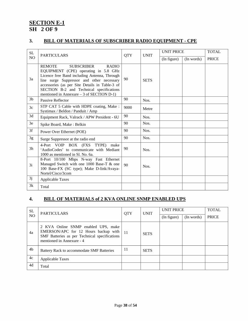
SECTION E-1 SH 2 OF 9 3. BILL OF MATERIALS OF SUBSCRIBER RADIO EQUIPMENT - CPE SL NO
PARTICULARS QTY UNIT UNIT PRICE TOTAL
PRICE (In figure) (In words)
3a
REMOTE SUBSCRIBER RADIO EQUIPMENT (CPE) operating in 5.8 GHz Licence free Band including Antenna, Through line surge Suppressor and other necessary accessories (as per Site Details in Table-3 of SECTION B-2 and Technical specifications mentioned in Annexure – 3 of SECTION D-1)
90 SETS
3b Passive Reflector 90 Nos.
3c STP CAT 5 Cable with HDPE coating, Make : Systimax / Beldon / Panduit / Amp
9000 Metre
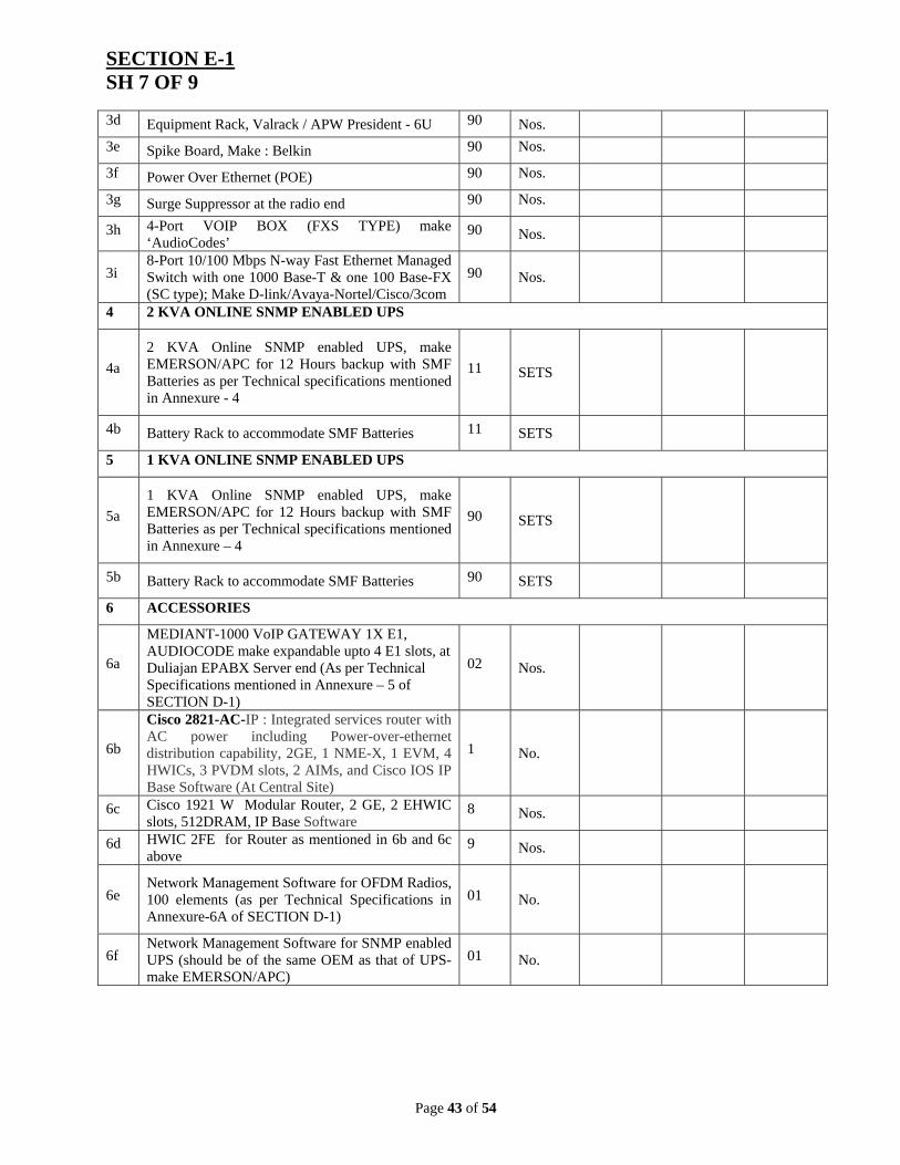
3d Equipment Rack, Valrack / APW President - 6U 90 Nos.
3e Spike Board, Make : Belkin 90 Nos.
3f Power Over Ethernet (POE) 90 Nos.
3g Surge Suppressor at the radio end 90 Nos.
3h 4-Port VOIP BOX (FXS TYPE) make ‘AudioCodes’ to communicate with Mediant 1000 as mentioned in Sl. No. 6a.
90 Nos.
3i
8-Port 10/100 Mbps N-way Fast Ethernet Managed Switch with one 1000 Base-T & one 100 Base-FX (SC type); Make D-link/Avaya-Nortel/Cisco/3com
90 Nos.
3j Applicable Taxes
3k Total
4. BILL OF MATERIALS of 2 KVA ONLINE SNMP ENABLED UPS SL NO
PARTICULARS QTY UNIT UNIT PRICE TOTAL
PRICE (In figure) (In words)
4a
2 KVA Online SNMP enabled UPS, make EMERSON/APC for 12 Hours backup with SMF Batteries as per Technical specifications mentioned in Annexure - 4
11 SETS
4b Battery Rack to accommodate SMF Batteries 11 SETS
4c Applicable Taxes
4d Total
Page 39 of 54
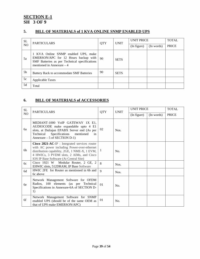
SECTION E-1 SH 3 OF 9 5. BILL OF MATERIALS of 1 KVA ONLINE SNMP ENABLED UPS SL NO
PARTICULARS QTY UNIT UNIT PRICE TOTAL
PRICE (In figure) (In words)
5a
1 KVA Online SNMP enabled UPS, make EMERSON/APC for 12 Hours backup with SMF Batteries as per Technical specifications mentioned in Annexure – 4
90 SETS
5b Battery Rack to accommodate SMF Batteries 90 SETS
5c Applicable Taxes
5d Total
6. BILL OF MATERIALS of ACCESSORIES SL NO
PARTICULARS QTY UNIT UNIT PRICE TOTAL
PRICE (In figure) (In words)
6a
MEDIANT-1000 VoIP GATEWAY 1X E1, AUDIOCODE make expandable upto 4 E1 slots, at Duliajan EPABX Server end (As per Technical Specifications mentioned in Annexure – 5 of SECTION D-1)
02 Nos.
6b
Cisco 2821-AC-IP : Integrated services router with AC power including Power-over-ethernet distribution capability, 2GE, 1 NME-X, 1 EVM, 4 HWICs, 3 PVDM slots, 2 AIMs, and Cisco IOS IP Base Software (At Central Site)
1 No.
6c Cisco 1921 W Modular Router, 2 GE, 2 EHWIC slots, 512DRAM, IP Base Software
8 Nos.
6d HWIC 2FE for Router as mentioned in 6b and 6c above
9 Nos.
6e
Network Management Software for OFDM Radios, 100 elements (as per Technical Specifications in Annexure-6A of SECTION D-1)
01 No.
6f Network Management Software for SNMP enabled UPS (should be of the same OEM as that of UPS make EMERSON/APC)
01 No.
Page 40 of 54
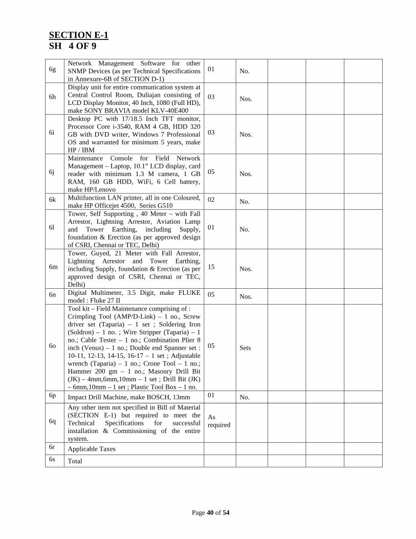
SECTION E-1 SH 4 OF 9
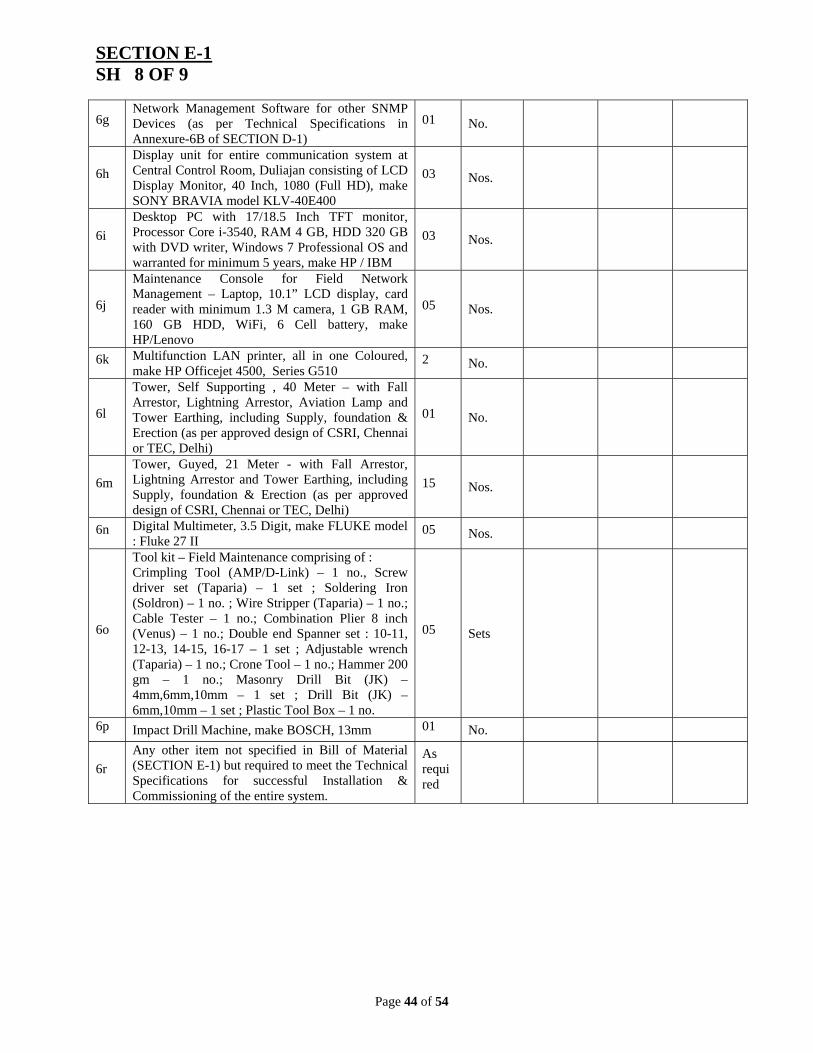
6g Network Management Software for other SNMP Devices (as per Technical Specifications in Annexure-6B of SECTION D-1)
01 No.
6h
Display unit for entire communication system at Central Control Room, Duliajan consisting of LCD Display Monitor, 40 Inch, 1080 (Full HD), make SONY BRAVIA model KLV-40E400
03 Nos.
6i
Desktop PC with 17/18.5 Inch TFT monitor, Processor Core i-3540, RAM 4 GB, HDD 320 GB with DVD writer, Windows 7 Professional OS and warranted for minimum 5 years, make HP / IBM
03 Nos.
6j
Maintenance Console for Field Network Management – Laptop, 10.1” LCD display, card reader with minimum 1.3 M camera, 1 GB RAM, 160 GB HDD, WiFi, 6 Cell battery, make HP/Lenovo
05 Nos.
6k Multifunction LAN printer, all in one Coloured, make HP Officejet 4500, Series G510
02 No.
6l
Tower, Self Supporting , 40 Meter – with Fall Arrestor, Lightning Arrestor, Aviation Lamp and Tower Earthing, including Supply, foundation & Erection (as per approved design of CSRI, Chennai or TEC, Delhi)
01 No.
6m
Tower, Guyed, 21 Meter with Fall Arrestor, Lightning Arrestor and Tower Earthing, including Supply, foundation & Erection (as per approved design of CSRI, Chennai or TEC, Delhi)
15 Nos.
6n Digital Multimeter, 3.5 Digit, make FLUKE model : Fluke 27 II
05 Nos.
6o
Tool kit – Field Maintenance comprising of : Crimpling Tool (AMP/D-Link) – 1 no., Screw driver set (Taparia) – 1 set ; Soldering Iron (Soldron) – 1 no. ; Wire Stripper (Taparia) – 1 no.; Cable Tester – 1 no.; Combination Plier 8 inch (Venus) – 1 no.; Double end Spanner set : 10-11, 12-13, 14-15, 16-17 – 1 set ; Adjustable wrench (Taparia) – 1 no.; Crone Tool – 1 no.; Hammer 200 gm – 1 no.; Masonry Drill Bit (JK) – 4mm,6mm,10mm – 1 set ; Drill Bit (JK) – 6mm,10mm – 1 set ; Plastic Tool Box – 1 no.
05 Sets
6p Impact Drill Machine, make BOSCH, 13mm 01 No.
6q
Any other item not specified in Bill of Material (SECTION E-1) but required to meet the Technical Specifications for successful installation & Commissioning of the entire system.
As required
6r Applicable Taxes
6s Total
Page 41 of 54
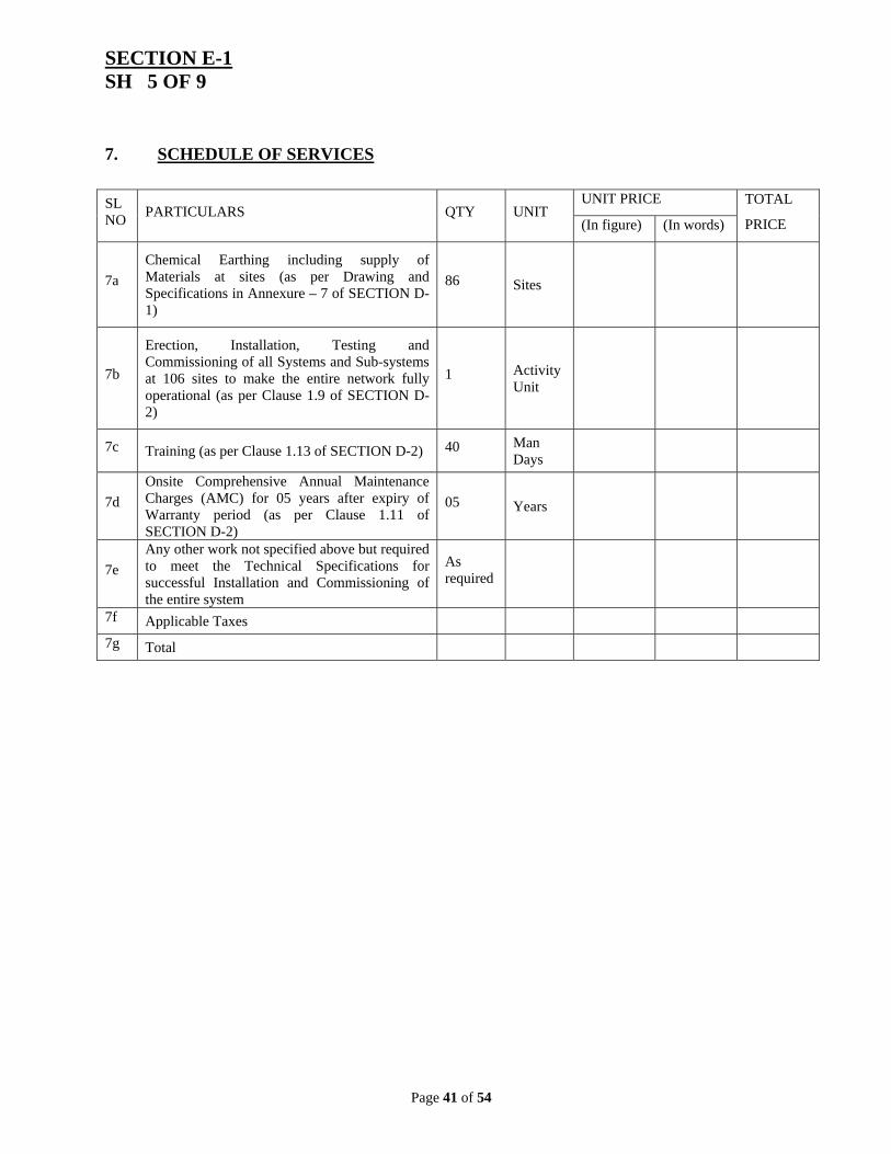
SECTION E-1 SH 5 OF 9
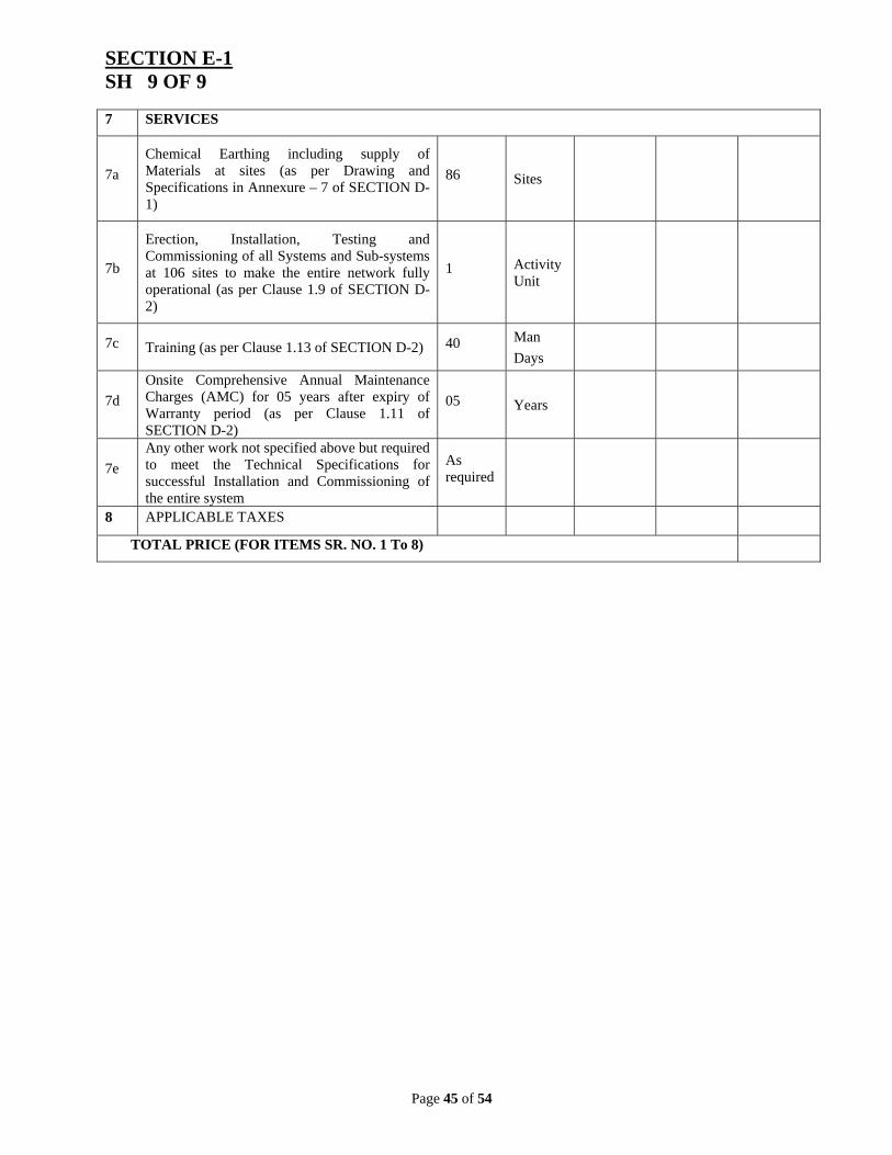
7. SCHEDULE OF SERVICES
SL NO
PARTICULARS QTY UNIT UNIT PRICE TOTAL
PRICE (In figure) (In words)
7a
Chemical Earthing including supply of Materials at sites (as per Drawing and Specifications in Annexure – 7 of SECTION D-1)
86 Sites
7b
Erection, Installation, Testing and Commissioning of all Systems and Sub-systems at 106 sites to make the entire network fully operational (as per Clause 1.9 of SECTION D-2)
1 Activity Unit
7c Training (as per Clause 1.13 of SECTION D-2) 40 Man Days
7d
Onsite Comprehensive Annual Maintenance Charges (AMC) for 05 years after expiry of Warranty period (as per Clause 1.11 of SECTION D-2)
05 Years
7e
Any other work not specified above but required to meet the Technical Specifications for successful Installation and Commissioning of the entire system
As required
7f Applicable Taxes
7g Total
Page 42 of 54
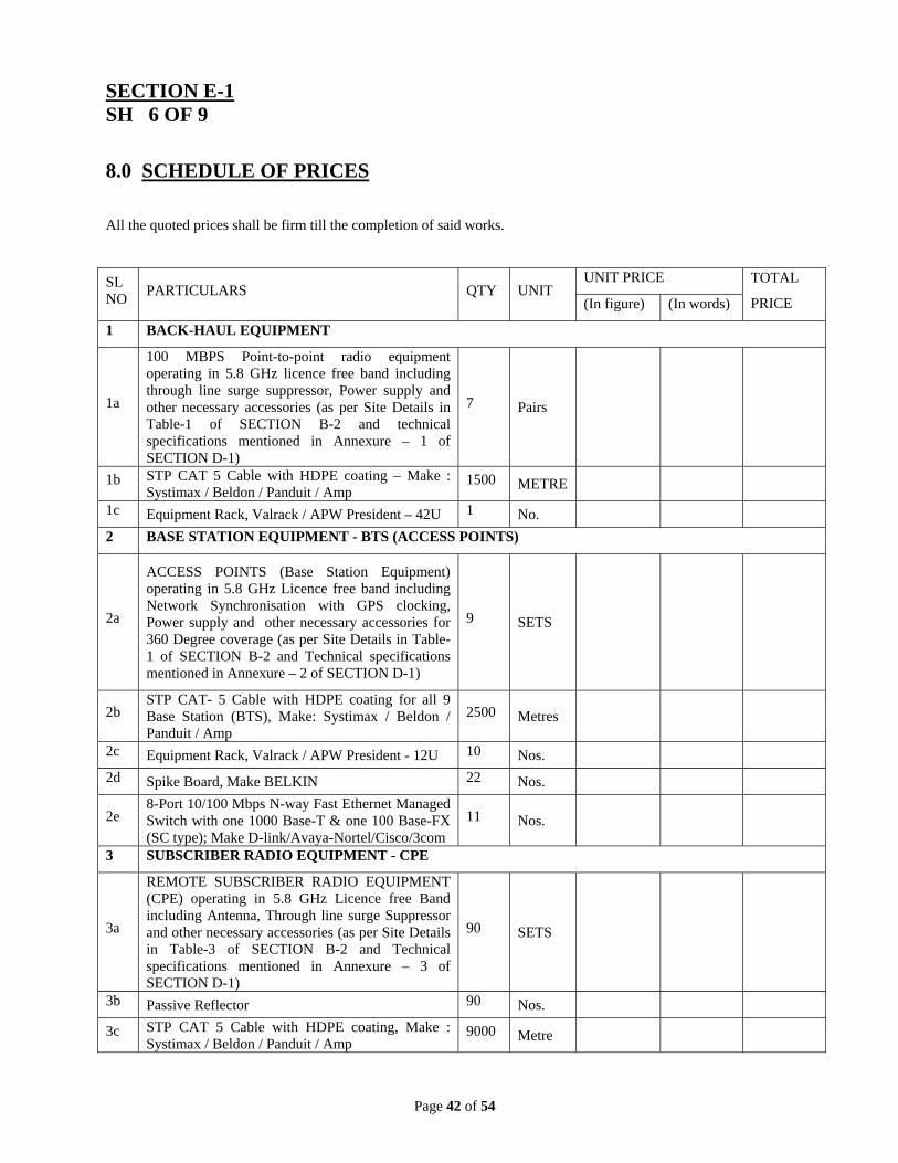
SECTION E-1 SH 6 OF 9
8.0 SCHEDULE OF PRICES
All the quoted prices shall be firm till the completion of said works.
SL NO
PARTICULARS QTY UNIT UNIT PRICE TOTAL
PRICE (In figure) (In words)
1 BACK-HAUL EQUIPMENT
1a
100 MBPS Point-to-point radio equipment operating in 5.8 GHz licence free band including through line surge suppressor, Power supply and other necessary accessories (as per Site Details in Table-1 of SECTION B-2 and technical specifications mentioned in Annexure – 1 of SECTION D-1)
7 Pairs
1b STP CAT 5 Cable with HDPE coating – Make : Systimax / Beldon / Panduit / Amp
ACCESS POINTS (Base Station Equipment) operating in 5.8 GHz Licence free band including Network Synchronisation with GPS clocking, Power supply and other necessary accessories for 360 Degree coverage (as per Site Details in Table-1 of SECTION B-2 and Technical specifications mentioned in Annexure – 2 of SECTION D-1)
9 SETS
2b STP CAT- 5 Cable with HDPE coating for all 9 Base Station (BTS), Make: Systimax / Beldon / Panduit / Amp
2e 8-Port 10/100 Mbps N-way Fast Ethernet Managed Switch with one 1000 Base-T & one 100 Base-FX (SC type); Make D-link/Avaya-Nortel/Cisco/3com
11 Nos.
3 SUBSCRIBER RADIO EQUIPMENT - CPE
3a
REMOTE SUBSCRIBER RADIO EQUIPMENT (CPE) operating in 5.8 GHz Licence free Band including Antenna, Through line surge Suppressor and other necessary accessories (as per Site Details in Table-3 of SECTION B-2 and Technical specifications mentioned in Annexure – 3 of SECTION D-1)
90 SETS
3b Passive Reflector 90 Nos.
3c STP CAT 5 Cable with HDPE coating, Make : Systimax / Beldon / Panduit / Amp
9000 Metre
Page 43 of 54
SECTION E-1 SH 7 OF 9 3d Equipment Rack, Valrack / APW President - 6U 90 Nos.
3e Spike Board, Make : Belkin 90 Nos.
3f Power Over Ethernet (POE) 90 Nos.
3g Surge Suppressor at the radio end 90 Nos.
3h 4-Port VOIP BOX (FXS TYPE) make ‘AudioCodes’
90 Nos.
3i 8-Port 10/100 Mbps N-way Fast Ethernet Managed Switch with one 1000 Base-T & one 100 Base-FX (SC type); Make D-link/Avaya-Nortel/Cisco/3com
90 Nos.
4 2 KVA ONLINE SNMP ENABLED UPS
4a
2 KVA Online SNMP enabled UPS, make EMERSON/APC for 12 Hours backup with SMF Batteries as per Technical specifications mentioned in Annexure - 4
11 SETS
4b Battery Rack to accommodate SMF Batteries 11 SETS
5 1 KVA ONLINE SNMP ENABLED UPS
5a
1 KVA Online SNMP enabled UPS, make EMERSON/APC for 12 Hours backup with SMF Batteries as per Technical specifications mentioned in Annexure – 4
90 SETS
5b Battery Rack to accommodate SMF Batteries 90 SETS
6 ACCESSORIES
6a
MEDIANT-1000 VoIP GATEWAY 1X E1, AUDIOCODE make expandable upto 4 E1 slots, at Duliajan EPABX Server end (As per Technical Specifications mentioned in Annexure – 5 of SECTION D-1)
02 Nos.
6b
Cisco 2821-AC-IP : Integrated services router with AC power including Power-over-ethernet distribution capability, 2GE, 1 NME-X, 1 EVM, 4 HWICs, 3 PVDM slots, 2 AIMs, and Cisco IOS IP Base Software (At Central Site)
1 No.
6c Cisco 1921 W Modular Router, 2 GE, 2 EHWIC slots, 512DRAM, IP Base Software
8 Nos.
6d HWIC 2FE for Router as mentioned in 6b and 6c above
9 Nos.
6e Network Management Software for OFDM Radios, 100 elements (as per Technical Specifications in Annexure-6A of SECTION D-1)
01 No.
6f Network Management Software for SNMP enabled UPS (should be of the same OEM as that of UPS- make EMERSON/APC)
01 No.
Page 44 of 54
SECTION E-1 SH 8 OF 9
6g Network Management Software for other SNMP Devices (as per Technical Specifications in Annexure-6B of SECTION D-1)
01 No.
6h
Display unit for entire communication system at Central Control Room, Duliajan consisting of LCD Display Monitor, 40 Inch, 1080 (Full HD), make SONY BRAVIA model KLV-40E400
03 Nos.
6i
Desktop PC with 17/18.5 Inch TFT monitor, Processor Core i-3540, RAM 4 GB, HDD 320 GB with DVD writer, Windows 7 Professional OS and warranted for minimum 5 years, make HP / IBM
03 Nos.
6j
Maintenance Console for Field Network Management – Laptop, 10.1” LCD display, card reader with minimum 1.3 M camera, 1 GB RAM, 160 GB HDD, WiFi, 6 Cell battery, make HP/Lenovo
05 Nos.
6k Multifunction LAN printer, all in one Coloured, make HP Officejet 4500, Series G510
2 No.
6l
Tower, Self Supporting , 40 Meter – with Fall Arrestor, Lightning Arrestor, Aviation Lamp and Tower Earthing, including Supply, foundation & Erection (as per approved design of CSRI, Chennai or TEC, Delhi)
01 No.
6m
Tower, Guyed, 21 Meter - with Fall Arrestor, Lightning Arrestor and Tower Earthing, including Supply, foundation & Erection (as per approved design of CSRI, Chennai or TEC, Delhi)
15 Nos.
6n Digital Multimeter, 3.5 Digit, make FLUKE model : Fluke 27 II
05 Nos.
6o
Tool kit – Field Maintenance comprising of : Crimpling Tool (AMP/D-Link) – 1 no., Screw driver set (Taparia) – 1 set ; Soldering Iron (Soldron) – 1 no. ; Wire Stripper (Taparia) – 1 no.; Cable Tester – 1 no.; Combination Plier 8 inch (Venus) – 1 no.; Double end Spanner set : 10-11, 12-13, 14-15, 16-17 – 1 set ; Adjustable wrench (Taparia) – 1 no.; Crone Tool – 1 no.; Hammer 200 gm – 1 no.; Masonry Drill Bit (JK) – 4mm,6mm,10mm – 1 set ; Drill Bit (JK) – 6mm,10mm – 1 set ; Plastic Tool Box – 1 no.
05 Sets
6p Impact Drill Machine, make BOSCH, 13mm 01 No.
6r
Any other item not specified in Bill of Material (SECTION E-1) but required to meet the Technical Specifications for successful Installation & Commissioning of the entire system.
As required
Page 45 of 54
SECTION E-1 SH 9 OF 9 7 SERVICES
7a
Chemical Earthing including supply of Materials at sites (as per Drawing and Specifications in Annexure – 7 of SECTION D-1)
86 Sites
7b
Erection, Installation, Testing and Commissioning of all Systems and Sub-systems at 106 sites to make the entire network fully operational (as per Clause 1.9 of SECTION D-2)
1 Activity Unit
7c Training (as per Clause 1.13 of SECTION D-2) 40 Man
Days
7d
Onsite Comprehensive Annual Maintenance Charges (AMC) for 05 years after expiry of Warranty period (as per Clause 1.11 of SECTION D-2)
05 Years
7e
Any other work not specified above but required to meet the Technical Specifications for successful Installation and Commissioning of the entire system
As required
8 APPLICABLE TAXES
TOTAL PRICE (FOR ITEMS SR. NO. 1 To 8)
Page 46 of 54
SECTION E-2 SH 1 OF 1
1.0 SCHEDULE OF DEVIATIONS All the deviations from the technical specifications shall be filled-in by the BIDDER clause by clause in this schedule.
SECTION SPECIFICATION NO. CLAUSE NO. DEVIATION
The BIDDER hereby certifies that the above mentioned are the only deviations from the client’s Technical specifications for this enquiry. The BIDDER further confirms that in the event of any other data and information presented in the BIDDER’S proposal and accompanying documents including drawings, catalogues, etc., are at variance with the specific requirements laid out in the Client’s technical specifications, then the latter shall govern and will be binding on the BIDDER for the quoted price.
SIGNATURE: --------------------- DESIGNATION: ------------------- COMPANY: ----------------------- COMPANY SEAL DATE: --------------------------
Page 47 of 54
SECTION E-3 SH 1 OF 1
1.0 BIDDER’S EXPERIENCE
The BIDDER shall furnish here a list of similar jobs executed by him to whom a reference may be made in case OIL considers such a reference necessary.
SL NO
NAME AND DESCRIPTION OF WORK
VALUE OF WORK
PERIOD OF EXECUTION AND DATE
CLIENT
PERSONS TO WHOM REFERENCE MAY BE MADE WITH CONTACT DETAILS
SIGNATURE: --------------------- DESIGNATION: ------------------- COMPANY: ----------------------- COMPANY SEAL DATE: --------------------------
Page 48 of 54
SECTION E-4
1.0 BIDDER’S EXPERIENCE
The BIDDER shall furnish here a list of similar jobs executed by him to whom a reference may be made in case OIL considers such a reference necessary.
SL NO
NAME AND DESCRIPTION OF WORK
VALUE OF WORK
PERIOD OF EXECUTION AND DATE
CLIENT
PERSONS TO WHOM REFERENCE MAY BE MADE WITH CONTACT DETAILS
SIGNATURE: --------------------- DESIGNATION: ------------------- COMPANY: ----------------------- COMPANY SEAL DATE: --------------------------
Page 49 of 54
AA. Standard Notes: 1) The tender is invited under SINGLE STAGE-TWO BID SYSTEM. The bidder has to submit both the “TECHNICAL” and “COMMERCIAL” bid through electronic form in the OIL’s e-Tender portal within the Bid Closing Date and Time stipulated in the e-Tender. The Technical Bid is to be submitted as per Scope of Work & Technical Specification of the tender and Commercial bid as per the Online Commercial Bid format. 2) In Technical Bid opening, only Collaboration Folder ( C folder ) will be opened. Therefore, the bidder should ensure that Technical bid is uploaded in the c-Folder link (collaboration link) under Un-priced Bid Tab Page only. No price should be given in above C folder, otherwise the offer will be rejected. Please go through the help document in detail before uploading the document. 3) The original bid security ( amount is mentioned above and also in Basic Data of the tender in OIL’s e-portal) should reach us before bid closing date and time of the technical bid. Bid without original Bid Security will be rejected. The bidders who are exempted from submitting the Bid Bond should attach documentary evidence in the Collaboration folder as per clause 8.8 of General Terms and Conditions vide MM/LOCAL/E-01/2005 for E-Procurement LCB Tenders. The Bid Security shall be valid for six months from the date of bid opening. 4) COMMERCIAL BIDS OF ONLY THOSE BIDDERS WILL BE OPENED WHOSE OFFERS ARE FOUND TO BE TECHNICALLY ACCEPTABLE. 5) OIL reserves the right to allow Small Scale Sectors registered with NSIC purchase preference facility as admissible as per existing Government Policy. The bidders are requested to check the latest position on the subject on their own and OIL does not accept any liability whatsoever, on this account. 6) To ascertain the substantial responsiveness of the bid OIL reserves the right to ask the bidder for clarification in respect of clauses covered under BRC also and such clarifications fulfilling the BRC clauses in toto must be received on or before the deadline given by the company, failing which the offer will be summarily rejected.
7) Price should be maintained in the “online price schedule” only. The price quoted in the “online price schedule” will only be considered.
8) All the Bids must be Digitally Signed using “Class 3” digital certificate (e-commerce application) only as per Indian IT Act obtained from the licensed Certifying Authorities operating under the Root Certifying Authority of India (RCAI), Controller of Certifying Authorities (CCA) of India. The bid signed using other than “Class 3” digital certificate, will be rejected.
9.) Offers should be valid for minimum 120 days from the date of Technical Bid closing Date, failing which offer shall be rejected.
Page 50 of 54
10) Integrity Pact is applicable against this tender. Therefore, please attach the Integrity Pact document duly signed along with your quotation as per BRC. The name of the OIL’s Independent External Monitors at present are as under : (A) SHRI N. GOPALASWAMI, I.A.S ( Retd) , Former Chief Election Commissioner of India E-mail Id : [email protected] (B) SHRI RAMESH CHANDRA AGARWAL , IPS( Retd) Former Director General of Police E-mail Id : [email protected]
Page 51 of 54
Annexure - II
BID REJECTION CRITERIA (BRC) / BID EVALUATION CRITERIA (BEC) In addition to BEC/BRC as per General Terms and Conditions vide MM/LOCAL/E-01/2005 for E-Procurement LCB Tenders, The following clause will be applicable against this tender: (I) BID REJECTION CRITERIA (BRC) The bids must conform to the specifications and terms and conditions given in the enquiry. Technical brochures of all the offered equipment have to be submitted without which offer will be summarily rejected. Bids shall be rejected in case the equipment offered do not conform to the required parameters stipulated in the Technical Specifications (Section – D1), Special Terms of the Contract (Section - D2) and Scope of Supply, Works and Services (Section – C).
Notwithstanding the general conformity of the bids to the stipulated specifications and terms and conditions, the following requirements shall have to be particularly met by the bidders, without which the offer will be considered as non-responsive and rejected: (A) TECHNICAL : 2.0 Bidder has to be the Original Equipment Manufacturer (OEM) or certified authorised
representative of the offered Radio equipment. In case the bidder is a certified authorized representative, valid authorization certificate from the OEM has to be submitted along with the bid.
3.0 Bidder must be in wireless network business for a period of at least last 3 (Three) continuous years preceding the Bid Closing Date. Bidder s are required to produce documentary evidence for the same in the prescribed format as given in Section E-4.
4.0 Bidder must have successfully supplied, installed and commissioned at least 2 (Two) nos. of wireless radio projects (each consisting of minimum 3 numbers of Point - to - Point & 3 numbers of Point - to - Multipoint configuration) in Central government / State government / PSUs / Oil & Gas organizations during last five financial years i.e. this year and previous four consecutive financial years.
5.0 Bidder must submit documentary evidence in the form of copy of Purchase Orders along with job completion certificates issued by the clients supporting the experience mentioned in Para 2 and 3 above.
6.0 Bidder must submit the design of the complete Radio system along with link engineering details of all calculations to meet the operational requirements for all the locations as mentioned in Technical specifications. In case Bidder is an authorized dealer or representative, design of the complete Radio system must be duly vetted by the OEM.
7.0 Bidder has to submit brochures in support of all compliances made under Complied / Non-complied column of all Annexure of Technical specifications Section D-1). Each compliance has to have a cross reference number to specification sheets / brochures attached along with technical bid failing which the bid will be considered incomplete. OIL INDIA LIMITED (OIL) reserves the right to summarily reject the bid in case such provision is not complied with.
8.0 Bidder must have supply and support base in North-East India and should have maintenance base at Duliajan, Assam.
9.0 Bidder (OEM) must confirm to provide maintenance support for 6 (Six) years after installation & commissioning of all the systems, subsystems & accessories (1 year
Page 52 of 54
warranty & 5 years AMC). This maintenance of support service should be extendable to another 4 (Four) years in case product is not discontinued. In case of discontinuance of product, such notice must be given to OIL at least six years in advance. If the bidder is a certified authorized representative, the bidder has to submit a certificate from OEM for the same.
10.0 Bidder has to quote firm comprehensive AMC rates as asked for in the SCHEDULE OF PRICES (E-1).
11.0 Wherever Bidder is quoting External hardware devices (VoIP boxes , UPS, Transient Voltage Surge Suppressor etc as mentioned in scope of work), the complete details of the product offered, make, configuration and warranty certificate from the respective OEMs and undertaking from respective vendors to provide support service for 06 (six)years has to be enclosed.
12.0 Incomplete information, non-submission of proofs, certificates, relevant brochures etc. shall be treated as non-compliance. If any information provided by bidder is found to be incorrect, the bid shall be rejected.
13.0 The bid shall be in accordance with the specification and shall be complete in all respects. The bidder shall clearly indicate in his offer Schedule of Prices (refer Section – E1), the list of deviations (refer section E-3) on separate sheet even though these may be mentioned somewhere else in the quotation.
(B) COMMERCIAL :
i). Bid security of ` 11,35,000.00 shall be submitted to Head-Materials, Oil India Limited,
Duliajan on or before the bid closing date.. If bid security in ORIGINAL of above mentioned amount is not received within bid closing date (upto 13:00hrs), the bid submitted through electronic form will be rejected without any further consideration. For exemption for submission of Bid Security, please refer Clause No. 8.8 of General Terms and Conditions vide MM/LOCAL/E-01/2005 for E-Procurement LCB Tenders. The Bid Security shall be valid for six month from the date of bid opening.
ii). The prices offered will have to be firm through delivery and not subject to variation on any account. Any bid submitted with an adjustable price will be treated as non-responsive and rejected.
iii). The complete supply shall be under guarantee / warrantee by the bidder for a minimum period of 18 months from the date of dispatch or 12 months from the date of successful commissioning of the complete unit at site whichever is earlier and confirm replacement of defective item, at their own expense within this period. During the warranty period, the equipment needs to function to the satisfaction of OIL. Offers not complying with this clause will be rejected.
iv). Successful bidder will be required to furnish a Performance Bank Guarantee @10% of the order value. For exemption for submission of Performance Bank Guarantee, please refer Clause No. 9.12 of General Terms and Conditions vide MM/LOCAL/E-01/2005 for E-Procurement LCB Tenders. The Performance Bank Guarantee must be valid for one year from the date of successful commissioning of the equipment or 18 months from the date of despatch whichever is earlier. Bidder must confirm the same in their bid. Offers not complying with this clause will be rejected.
v). The bank Guarantee should be allowed to be encashed at all branches within India
Page 53 of 54
vi). Bids received after the bid closing date and time will be rejected. Similarly, modifications to bids received after the bid closing date & time will not be considered.
vii). Validity of the bid shall be minimum 120 days from the Bid Closing Date. Bids with lesser validity will be rejected.
viii). Bids containing incorrect statement will be rejected.
ix). All the Bids must be Digitally Signed using “Class 3” digital certificate (e-commerce application) as per Indian IT Act obtained from the licensed Certifying Authorities operating under the Root Certifying Authority of India (RCAI), Controller of Certifying Authorities (CCA) of India. The bid signed using other than “Class 3” digital certificate, will be rejected.
x). C Folder is meant for Technical bid only. Therefore, no price should be given in C Folder, otherwise the offer will be rejected.
xi). Price should be maintained in the “online price schedule” only. The price quoted other than “online price schedule” only will not be considered except as per Schedule of Prices under Section E-1.
xii). The prices offered will have to be firm through delivery and not subject to variation on any account. A bid submitted with an adjustable price will be treated as non-responsive and rejected.
xiii). Integrity Pact: OIL shall be entering into an Integrity Pact with the bidders as per format enclosed vide Annexure V of the tender document. This Integrity Pact proforma has been duly signed digitally by OIL’s competent signatory. The proforma has to be returned by the bidder (along with the technical bid) duly signed (digitally) by the same signatory who signed the bid, i.e. who is duly authorized to sign the bid. Any bid not accompanied by Integrity Pact Proforma duly signed (digitally) by the bidder shall be rejected straightway. Uploading the Integrity Pact with digital signature will be construed that all pages of the Integrity Pact has been signed by the bidder’s authorized signatory who signed the Bid.has been
2.0 BID EVALUATION CRITERIA (BEC) The bids conforming to the specifications, terms and conditions stipulated in the enquiry and considered to be responsive, subjecting to the Bid Rejection Criteria, will be considered for further evaluation as per the Bid Evaluation Criteria given below :
(A) TECHNICAL : All materials as mentioned in the Tender should be offered. If any of the item is not offered by the bidder, the offer will not be considered for evaluation.
Page 54 of 54
(B) COMMERCIAL : The bids conforming to the technical specifications, terms and conditions stipulated in the tender and considered to be responsive after subjecting to the Bid Rejection Criteria as well as verification of original of any or all documents/ documentary evidences pertaining to BRC, will be considered for further evaluation as per the Bid Evaluation Criteria given below:
i). Bid will be evaluated taking into consideration Total FOR Destination Value for all the items numbered 1 to 8 in Schedule of Prices in Section E-1 (which includes among others Cost of Equipment, Installation, Commissioning and 5 years AMC charges) in the same Schedule of Prices, quoted by the bidder.
ii). To evaluate the inter-se-ranking of the offers, Assam Entry Tax on purchase value will be loaded as per prevailing Govt. of Assam guidelines as applicable on bid closing date. Bidders may check this with the appropriate authority while submitting their offer.
iii). Other terms and conditions of the enquiry shall be as per General Terms and Conditions for Indigenous Tender vide ANNEXURE-MM/TENDER/LP/01/06. However, if any of the Clauses of the Bid Rejection Criteria / Bid Evaluation Criteria (BEC / BRC) contradict the Clauses of the tender or ANNEXURE-MM/TENDER/LP/01/06 elsewhere, those in the BEC / BRC shall prevail.