ENGINEERING YOUR SUCCESS. OIL-X EVOLUTION High Efficiency Compressed Air Filters aerospace climate control electromechanical filtration fluid & gas handling hydraulics pneumatics process control sealing & shielding
Transcript
ENGINEERING YOUR SUCCESS.
OIL-X EVOLUTIONHigh Efficiency Compressed Air Filters
aerospaceclimate controlelectromechanicalfiltrationfluid & gas handlinghydraulicspneumaticsprocess controlsealing & shielding
Compressed air contamination is a real problem for industryIn today’s modern production facilities, the use of compressed air is often pivotal to manufacturing processes. Irrespective of whether the compressed air comes into direct contact with the product or is used to automate a process, provide motive power, or even to generate other gases on-site, a clean, dry, reliable compressed air supply is essential to maintain efficient and cost effective production.
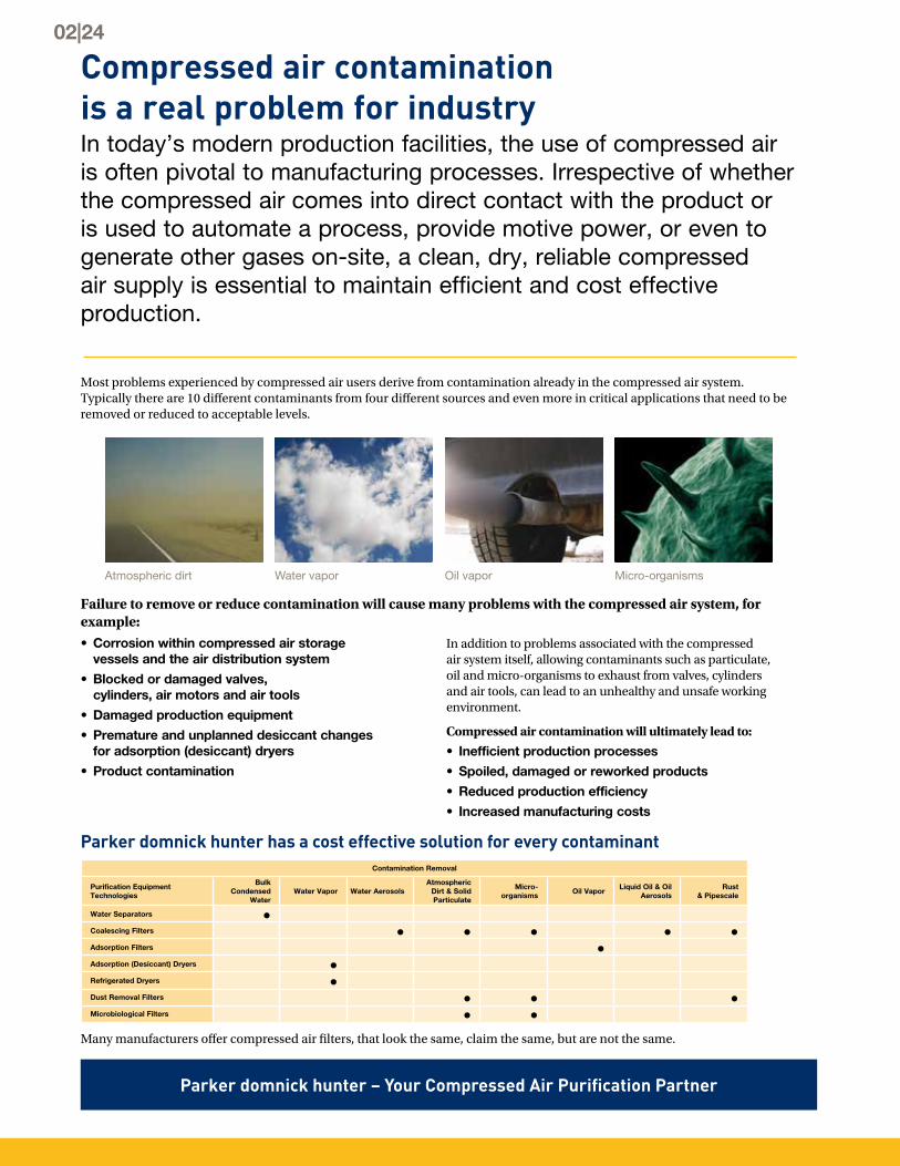
Most problems experienced by compressed air users derive from contamination already in the compressed air system. Typically there are 10 different contaminants from four different sources and even more in critical applications that need to be removed or reduced to acceptable levels.
Many manufacturers offer compressed air filters, that look the same, claim the same, but are not the same.
Parker domnick hunter – Your Compressed Air Purification Partner
Parker domnick hunter has a cost effective solution for every contaminant
• Corrosion within compressed air storage vessels and the air distribution system
• Blocked or damaged valves, cylinders, air motors and air tools
• Damaged production equipment
• Premature and unplanned desiccant changes for adsorption (desiccant) dryers
• Product contamination
In addition to problems associated with the compressed air system itself, allowing contaminants such as particulate, oil and micro-organisms to exhaust from valves, cylinders and air tools, can lead to an unhealthy and unsafe working environment.
Compressed air contamination will ultimately lead to:
• Inefficient production processes
• Spoiled, damaged or reworked products
• Reduced production efficiency
• Increased manufacturing costs
Failure to remove or reduce contamination will cause many problems with the compressed air system, for example:
The origins of modern compressed air filtration can be traced back to domnick hunter in 1963, it was the first company to use microfiber filter media for purification applications, changing the compressed air industry forever.
The OIL-X filter range was the first filter range to fully utilize this ground breaking technology and has always been synonymous with high quality compressed air. Now in the 21st century, the OIL-X name remains, but the technology has evolved beyond recognition.
Parker domnick hunter OIL-X EVOLUTIONSince the introduction of the first OIL-X range, Parker domnick hunter has continued to develop both the compressed air filter and the standards governing compressed air quality. Constantly innovated, OIL-X EVOLUTION has become the leading technology for compressed air filtration, providing the exact balance between air quality, energy efficiency and low lifetime costs.
Parker domnick hunter - The original name in Compressed Air Purification
INTERNATIONAL APPROVALS
ASME VIII CRN
AS1210
ISO9001:2000 ISO14001
APPROVALS, ACCREDITATIONS AND ASSOCIATIONS
Parker domnick hunter has been supplying industry with high efficiency filtration and purification products since 1963. Our philosophy ‘Designed for Air Quality & Energy Efficiency’ ensures products that not only provide the user with clean, high quality compressed air, but also with low lifetime costs and reduced CO2 emissions.
• Industry leading design
• World-wide approvals for safety and reliability
• Meets or exceeds the requirements for delivered air quality shown in all editions of ISO8573-1, the international standard for compressed air quality
• Fully tested in accordance with ISO12500-1
• Performance independently validated by Lloyds Register
• The only filter range to offer a one year air quality guarantee
• 10 years guarantee on filter housings
• World-wide Parker support network
• OIL-X EVOLUTION - often copied, never matched
Air QualityThe primary reason for using a compressed air filter is to remove contamination and improve air quality. Parker domnick hunter’s design Philosophy of Air Quality & Energy Efficiency has led to a product that provides:
• Highest air quality• Lowest power consumption• Lowest operational differential pressure
• Lowest CO2 emissions• Lowest total cost of ownership
Air Quality ClaimsMost compressed air filter manufacturers claim that the delivered air from their filters complies with the quality classifications of ISO8573 part 1 when tested with the methods and equipment stated in ISO8573 parts 2-9, but how do they really perform?
04|24
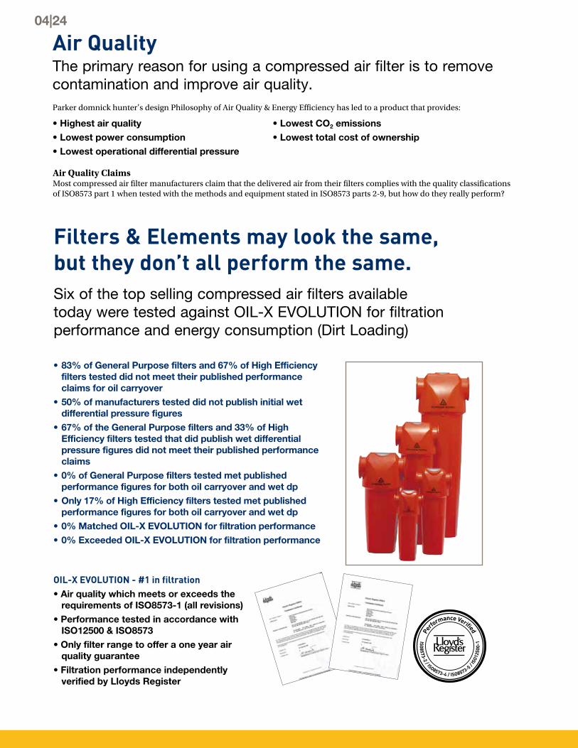
Filters & Elements may look the same, but they don’t all perform the same.Six of the top selling compressed air filters available today were tested against OIL-X EVOLUTION for filtration performance and energy consumption (Dirt Loading)
• 83% of General Purpose filters and 67% of High Efficiency filters tested did not meet their published performance claims for oil carryover
• 50% of manufacturers tested did not publish initial wet differential pressure figures
• 67% of the General Purpose filters and 33% of High Efficiency filters tested that did publish wet differential pressure figures did not meet their published performance claims
• 0% of General Purpose filters tested met published performance figures for both oil carryover and wet dp
• Only 17% of High Efficiency filters tested met published performance figures for both oil carryover and wet dp
• 0% Matched OIL-X EVOLUTION for filtration performance• 0% Exceeded OIL-X EVOLUTION for filtration performance
OIL-X EVOLUTION - #1 in filtration• Air quality which meets or exceeds the
requirements of ISO8573-1 (all revisions)• Performance tested in accordance with
ISO12500 & ISO8573• Only filter range to offer a one year air
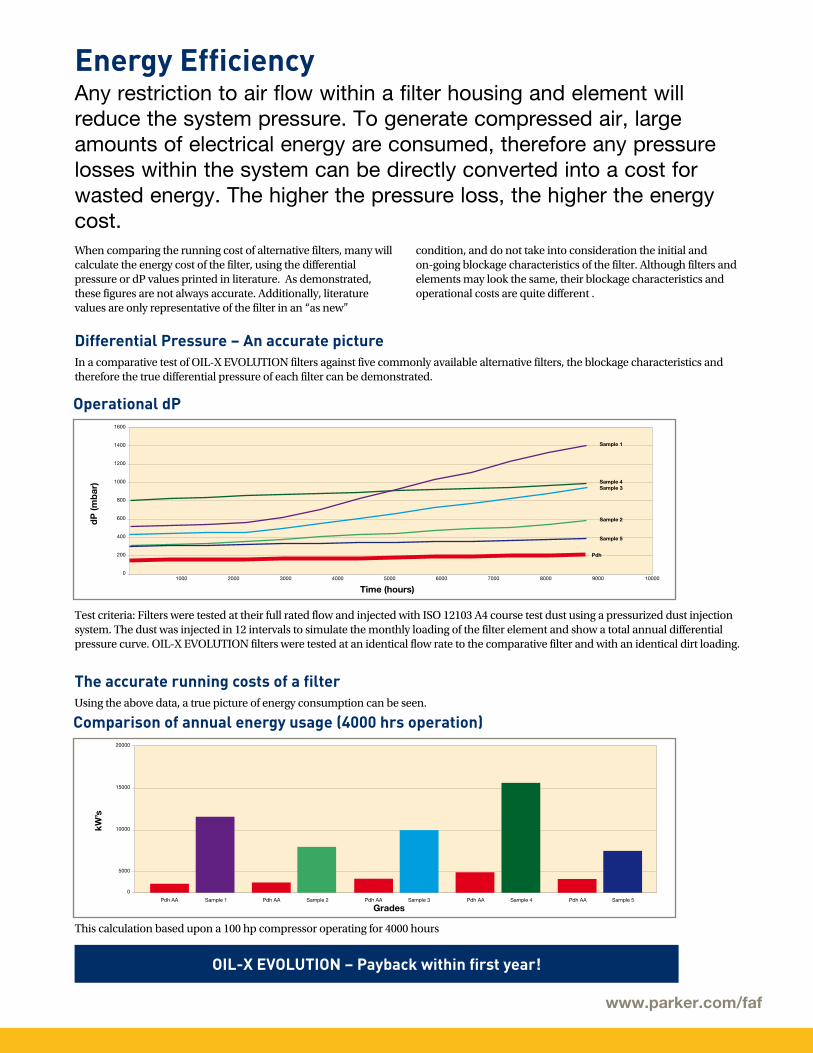
Energy Efficiency Any restriction to air flow within a filter housing and element will reduce the system pressure. To generate compressed air, large amounts of electrical energy are consumed, therefore any pressure losses within the system can be directly converted into a cost for wasted energy. The higher the pressure loss, the higher the energy cost.When comparing the running cost of alternative filters, many will calculate the energy cost of the filter, using the differential pressure or dP values printed in literature. As demonstrated, these figures are not always accurate. Additionally, literature values are only representative of the filter in an “as new”
condition, and do not take into consideration the initial and on-going blockage characteristics of the filter. Although filters and elements may look the same, their blockage characteristics and operational costs are quite different .
In a comparative test of OIL-X EVOLUTION filters against five commonly available alternative filters, the blockage characteristics and therefore the true differential pressure of each filter can be demonstrated.
Using the above data, a true picture of energy consumption can be seen.
Test criteria: Filters were tested at their full rated flow and injected with ISO 12103 A4 course test dust using a pressurized dust injection system. The dust was injected in 12 intervals to simulate the monthly loading of the filter element and show a total annual differential pressure curve. OIL-X EVOLUTION filters were tested at an identical flow rate to the comparative filter and with an identical dirt loading.
This calculation based upon a 100 hp compressor operating for 4000 hours
1000
200
400
600
800
1000
1200
1400
1600
02000 3000 4000 5000 6000 7000 8000 9000 10000
Time (hours)
Pdh
Sample 5
Sample 2
Sample 3Sample 4
Sample 1
dP
(mb
ar)
5000
10000
15000
20000
0
Grades
kW’s
Pdh AA Sample 1 Pdh AA Sample 2 Pdh AA Sample 3 Pdh AA Sample 4 Sample 5Pdh AA
Operational dP
Comparison of annual energy usage (4000 hrs operation)
Differential Pressure – An accurate picture
The accurate running costs of a filter
OIL-X EVOLUTION – Payback within first year!
www.parker.com/faf
OIL-X EVOLUTIONThe most energy efficient compressed air filters in the world.
2000
4000
8000
6000
10000
12000
0
Filters compared
Tota
l co
st o
f o
wne
rshi
p
Pdh AA Sample 1 Pdh AA Sample 4 Pdh AA Sample 5Pdh AA Sample 3Pdh AA Sample 2
Purchase Cost Running Cost Replacement Element Cost
Five years total cost of ownership
Low Lifetime Cost A filter with a low purchase price may not always turn out to be the most cost effective solution
2000
4000
8000
6000
10000
0
Filters compared
Kg
/CO
2
Pdh AA Sample 1 Pdh AA Sample 4 Pdh AA Sample 5Pdh AA Sample 3Pdh AA Sample 2
Comparison of annual CO2 emissions (4000 hrs Operation)
Reduced CO2 Emissions Many countries worldwide are looking closely at their manufacturing industries in an effort to reduce the amount of harmful greenhouse gases released into the atmosphere. The use of electricity has a direct impact on
the generation and release of CO2. By significantly reducing the energy consumption of its products, Parker can help you to reduce your carbon footprint and protect the environment.
Calculation based upon initial purchase price of the filter housing, cost of 0.15¢ per kWH and five annual filter element changes. An estimated annual increase of 3% was included on both energy costs and element price.
Calculation assumes 1KwH emits 0.544 Kg/CO2 (Information provided by UK Carbon Trust at time of publication)
And remember, not all filters achieved their claimed air quality!
OIL-X EVOLUTION - The environmentally friendly filter
06|24
• The world’s most energy efficient Water Separators
• For the removal of bulk condensed water and liquid oil
• Used to protect coalescing filters from bulk liquid contamination
• High liquid removal efficiencies at all flow conditions
• Tested in accordance with ISO8573-9
OIL-X EVOLUTION Water Separators - Grade WS
In addition to protecting coalescing filters from bulk liquid contamination, Grade WS Water Separators can be used on compressor inter-cooler and after-cooler stages, wet air receivers and refrigerated dryers.
How OIL-X EVOLUTION Water Separators workParker domnick hunter OIL-X EVOLUTION WS Water Separators utilize centrifugal technology which provides a more efficient method of bulk liquid removal. Using a combination of direction change and centrifugal action, water is effectively separated from the compressed air flow. Parker domnick hunter centrifugal separators are very efficient with varying flow conditions and have been further optimized to reduce energy costs.
• Wet air enters the inlet port and is directed into the separator module fixed turning vanes causing the air to spin inside the vessel and then change direction as it passes the impinger.
• A vortex is then created which narrows and intensifies as it reaches the lower part of the separator.
• Bulk liquid is therefore removed from the air stream due to a combination of:
- Directional changes of the air stream.
- Velocity changes.
- Centrifugal action of the vortex.
• As the vortex reaches the bottom of the separator module, air is forced through the center of the vortex.
• Aerospace turning vanes located in the outlet of the separator module now turn an “inefficient corner” into a number of more “efficient corners” to reduce turbulence, minimize pressure loss and therefore operational costs.
www.parker.com/faf
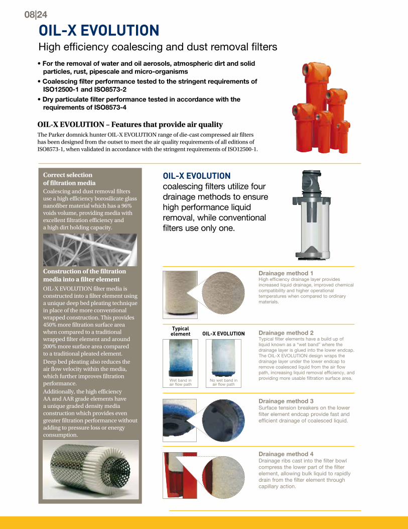
OIL-X EVOLUTIONHigh efficiency coalescing and dust removal filters
Correct selection of filtration mediaCoalescing and dust removal filters use a high efficiency borosilicate glass nanofiber material which has a 96% voids volume, providing media with excellent filtration efficiency and a high dirt holding capacity.
Construction of the filtration media into a filter elementOIL-X EVOLUTION filter media is constructed into a filter element using a unique deep bed pleating technique in place of the more conventional wrapped construction. This provides 450% more filtration surface area when compared to a traditional wrapped filter element and around 200% more surface area compared to a traditional pleated element.Deep bed pleating also reduces the air flow velocity within the media, which further improves filtration performance.Additionally, the high efficiency AA and AAR grade elements have a unique graded density media construction which provides even greater filtration performance without adding to pressure loss or energy consumption.
Drainage method 3Surface tension breakers on the lower filter element endcap provide fast and efficient drainage of coalesced liquid.
Drainage method 4Drainage ribs cast into the filter bowl compress the lower part of the filter element, allowing bulk liquid to rapidly drain from the filter element through capillary action.
Drainage method 2Typical filter elements have a build up of liquid known as a “wet band” where the drainage layer is glued into the lower endcap.The OIL-X EVOLUTION design wraps the drainage layer under the lower endcap to remove coalesced liquid from the air flow path, increasing liquid removal efficiency, and providing more usable filtration surface area.
Typical element OIL-X EVOLUTION
Wet band in air flow path
No wet band in air flow path
Drainage method 1High efficiency drainage layer provides increased liquid drainage, improved chemical compatibility and higher operational temperatures when compared to ordinary materials.
OIL-X EVOLUTION coalescing filters utilize four drainage methods to ensure high performance liquid removal, while conventional filters use only one.
• For the removal of water and oil aerosols, atmospheric dirt and solid particles, rust, pipescale and micro-organisms
• Coalescing filter performance tested to the stringent requirements of ISO12500-1 and ISO8573-2
• Dry particulate filter performance tested in accordance with the requirements of ISO8573-4
OIL-X EVOLUTION – Features that provide air qualityThe Parker domnick hunter OIL-X EVOLUTION range of die-cast compressed air filters has been designed from the outset to meet the air quality requirements of all editions of ISO8573-1, when validated in accordance with the stringent requirements of ISO12500-1.
08|24
Specialist media treatmentAll OIL-X EVOLUTION coalescing and dust removal filter media includes a specialist treatment. This actively repels oil and water to ensure that coalesced liquid does not reduce the voids volume. Maintaining a high voids volume reduces the risk of premature blockage, system pressure losses and high energy consumption.
Deep bed pleatingDeep bed pleating reduces the air flow velocity within the filtration media. This both improves filtration performance of the filter element and also reduces pressure losses.
OIL-X EVOLUTION die-cast filters optimized flow path from patented Aerospace Flow Management System
Providing an optimal flow path for the compressed air through the filter housing and element is key to reducing system operating costs
Pressure losses in a compressed air filter is a combination of fixed pressure losses and incremental pressure losses. Fixed pressure losses are derived from the filter housing and the interface between the filter housing and filter element.Incremental pressure losses are directly related to the filter element as it blocks up with contamination. In most filters, high operational costs can be attributed to an inefficient air flow path within the filter housing and element and poorly selected filtration media. In addition to this, the high differential pressure “change points” recommended by many filter manufacturers increase operational costs even further.
“Bell mouth” housing inlet & full flow inlet conduit
Flow distributor
Conical flow diffuser
Smooth 90° elbow & aerospace turning vanes
Inlet Outlet
OIL-X EVOLUTION – Features providing energy efficiencyIn these times of increasing energy costs, an efficient and cost effective manufacturing process is a major factor in maintaining the profitability and growth of your business. All Parker domnick hunter products are designed to not only minimize the use of compressed air and electrical energy in their operation, but also to significantly reduce the operational costs of the compressor by minimizing pressure losses.
OIL-X EVOLUTION filters incorporate a number of unique and patented design features to minimize differential pressure and provide a filter and element combination where the differential pressure starts low and stays low to maximize energy savings and provide the lowest lifetime costs without compromising air quality.
www.parker.com/faf
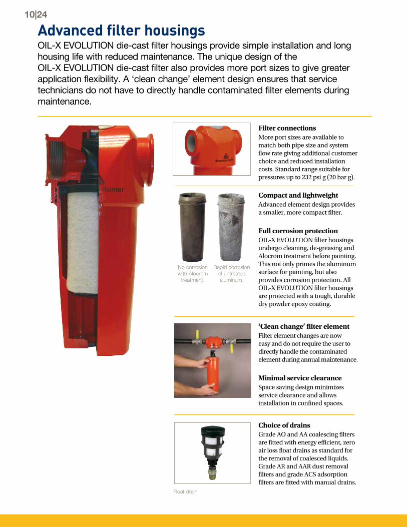
Advanced filter housings OIL-X EVOLUTION die-cast filter housings provide simple installation and long housing life with reduced maintenance. The unique design of the OIL-X EVOLUTION die-cast filter also provides more port sizes to give greater application flexibility. A ‘clean change’ element design ensures that service technicians do not have to directly handle contaminated filter elements during maintenance.
Filter connectionsMore port sizes are available to match both pipe size and system flow rate giving additional customer choice and reduced installation costs. Standard range suitable for pressures up to 232 psi g (20 bar g).
‘Clean change’ filter elementFilter element changes are now easy and do not require the user to directly handle the contaminated element during annual maintenance.
Minimal service clearanceSpace saving design minimizes service clearance and allows installation in confined spaces.
Choice of drainsGrade AO and AA coalescing filters are fitted with energy efficient, zero air loss float drains as standard for the removal of coalesced liquids. Grade AR and AAR dust removal filters and grade ACS adsorption filters are fitted with manual drains.
Compact and lightweightAdvanced element design provides a smaller, more compact filter.
Full corrosion protectionOIL-X EVOLUTION filter housings undergo cleaning, de-greasing and Alocrom treatment before painting. This not only primes the aluminum surface for painting, but also provides corrosion protection. All OIL-X EVOLUTION filter housings are protected with a tough, durable dry powder epoxy coating.
Float drain
Rapid corrosion of untreated aluminum.
No corrosion with Alocrom
treatment.
10|24
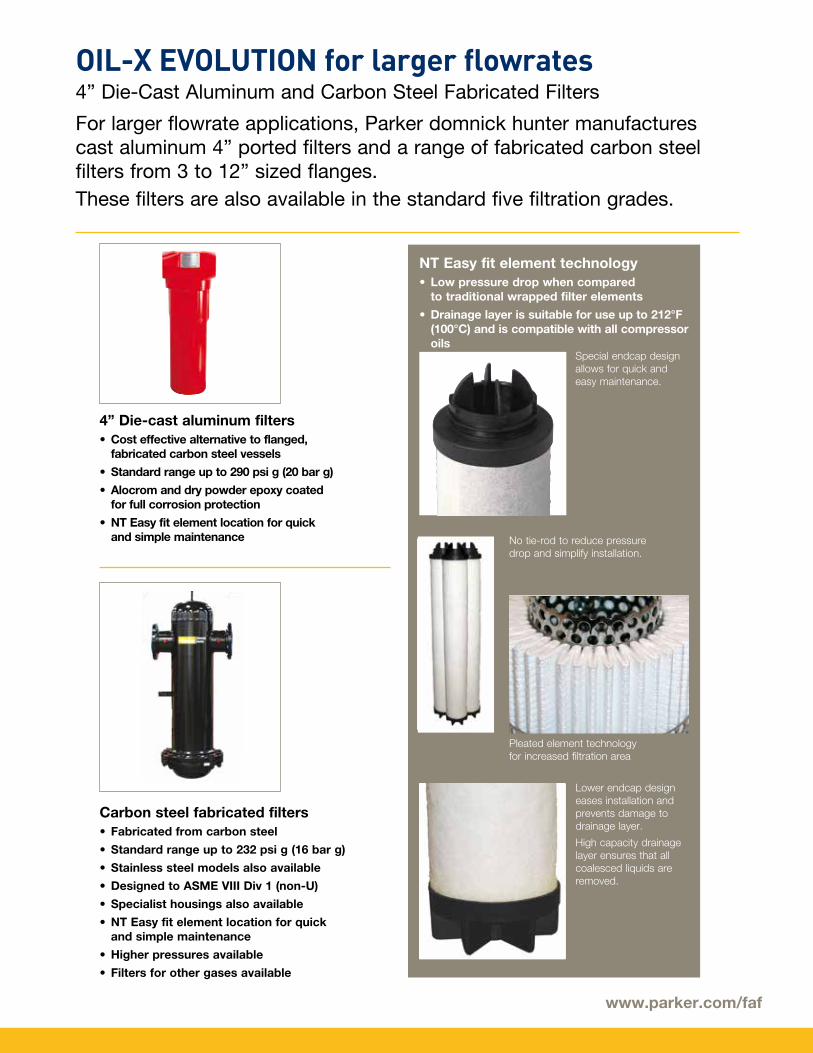
OIL-X EVOLUTION for larger flowrates4” Die-Cast Aluminum and Carbon Steel Fabricated Filters
For larger flowrate applications, Parker domnick hunter manufactures cast aluminum 4” ported filters and a range of fabricated carbon steel filters from 3 to 12” sized flanges.These filters are also available in the standard five filtration grades.
4” Die-cast aluminum filters• Cost effective alternative to flanged,
fabricated carbon steel vessels
• Standard range up to 290 psi g (20 bar g)
• Alocrom and dry powder epoxy coated for full corrosion protection
• NT Easy fit element location for quick and simple maintenance
NT Easy fit element technology• Low pressure drop when compared
to traditional wrapped filter elements
• Drainage layer is suitable for use up to 212°F (100°C) and is compatible with all compressor oils
Carbon steel fabricated filters• Fabricated from carbon steel
• Standard range up to 232 psi g (16 bar g)
• Stainless steel models also available
• Designed to ASME VIII Div 1 (non-U)
• Specialist housings also available
• NT Easy fit element location for quick and simple maintenance
• Higher pressures available
• Filters for other gases available
No tie-rod to reduce pressure drop and simplify installation.
Special endcap design allows for quick and easy maintenance.
Lower endcap design eases installation and prevents damage to drainage layer.
High capacity drainage layer ensures that all coalesced liquids are removed.
Pleated element technology for increased filtration area
www.parker.com/faf
OIL-X EVOLUTION - OVR Oil Vapor Removal
Removing oil vapor from compressed air is necessary to meet the air quality standards required by many critical applications and processes within industries such as pharmaceutical, medical, chemical, electronics, food and beverage and breathing air applications.
OIL-X EVOLUTION adsorption filters utilize two types of adsorbent:
• OIL-X EVOLUTION - Grade AC use a combination of both adsorbents (depending upon flow rate)
Parker domnick hunter use adsorption filter technology for the removal of oil vapors. The OIL-X EVOLUTION range consists of three types of oil vapor removal filters, modular carbon towers - Grade OVR, single stage in-line filters - Grade ACS and double stage in-line filters – Grade AC which consist of both coalescing and adsorption filter elements combined into one unit.
Oil vapor removal filters are selected based upon their position in the system and the frequency with which the elements can be changed.
OIL-X EVOLUTION Grade OVR can be used for both plant scale
protection and at the point of use. OIL-X EVOLUTION Grade OVR filters are also used when frequent element changes cannot be tolerated by the user.
OIL-X EVOLUTION Grades ACS and AC are used for smaller flow rate applications, point of use applications and applica-tions where more frequent element changes can be tolerated.
Oil vapor is oil in a gaseous form and will pass straight through coalescing filters which are designed to remove liquid oil and oil aerosols.
Grade OVR
Carbon granules 100% activated carbon cloth
Grade ACS Grade AC
12|24
Maintaining Air QualityAnnual filter element changes are essential (coalescing and dust removal filters)
Annual filter element changes ensure:
• Optimal performance is maintained
• Air quality continues to meets international standards
• Protection of downstream equipment, personnel and processes
• Low operational costs
• Increased productivity and profitability
• Peace of mind
To maintain your guaranteed air quality, filter elements must be replaced every year with genuine Parker domnick hunter parts.
Throughout its’ life, the filter element is constantly under bombardment from oily, acidic condensate and high velocity dirt particles, which it has to remove and retain to protect your compressed air system. Over time, this can weaken the filter media and reduce filtration performance. This potential but critical reduction in filtration performance cannot be detected by simple differential pressure monitoring techniques.
Annual filter element changes are therefore essential and failure to replace every year could result in reduced production performance, degrading air quality and increased operational costs.
Maintenance of oil vapor removal filtersUnlike oil aerosol removal filters which are changed annually to guarantee compressed air quality, the lifetime of an oil vapor removal filter can be attributed to various factors and require more frequent changes (unless OVR is used which is sized for 6000 hrs life).
Oil vapor concentration The higher the inlet concentration of oil vapor, the faster the activated carbon capacity will expire.
Bulk oil Adsorption filters are designed to remove oil vapor and odors, not liquid oil or aerosols. Poorly maintained or non-existent pre-filtration will cause the OVR filter capacity to quickly expire.
Temperature Oil vapor content increases proportionally to inlet temperature, reducing element life. Additionally, as temperature increases, the adsorption capacity decreases, again reducing element life.
Relative Humidity or Dewpoint Wet air reduces the adsorptive capacity of the carbon – always try to install an adsorption filter after a dryer.
Compressor oil changes When compressor oil is changed, the new lubricant burns off “light ends” which increases the oil vapor content for hours or even weeks afterwards. This increase in oil vapor content is adsorbed by the OVR filter, significantly reducing its adsorptive life.
Factors affecting the lifetime of adsorption filters
www.parker.com/faf
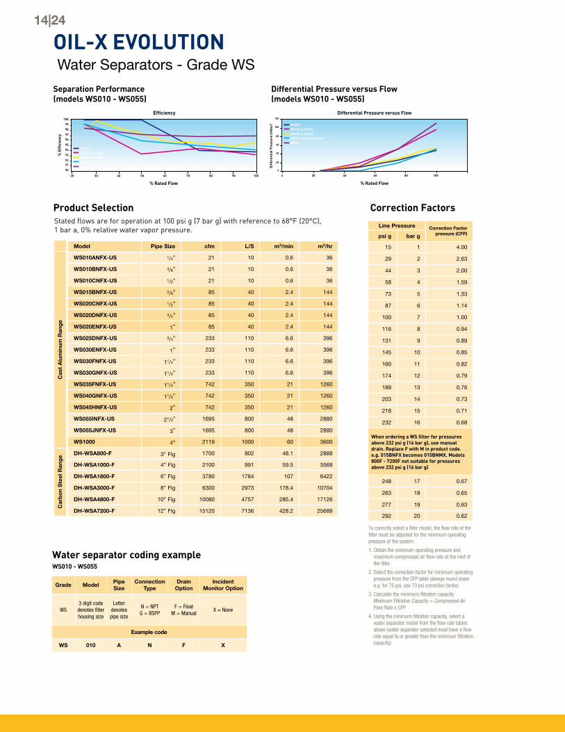
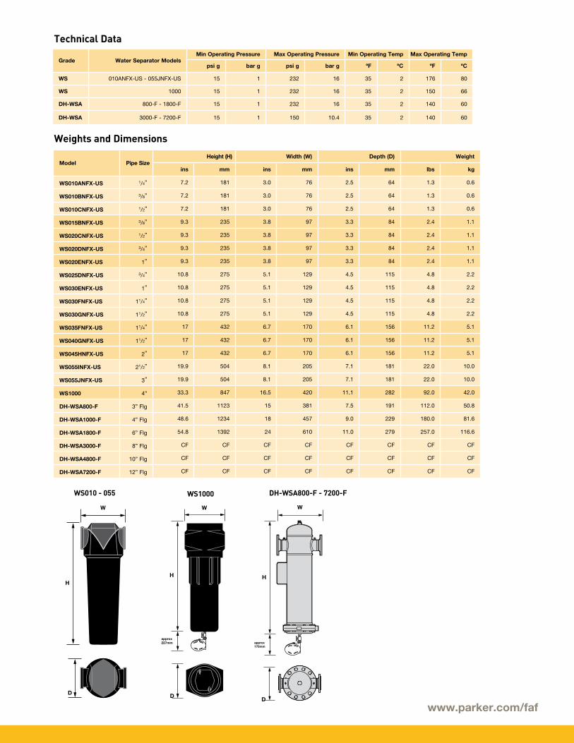
OIL-X EVOLUTION Water Separators - Grade WS
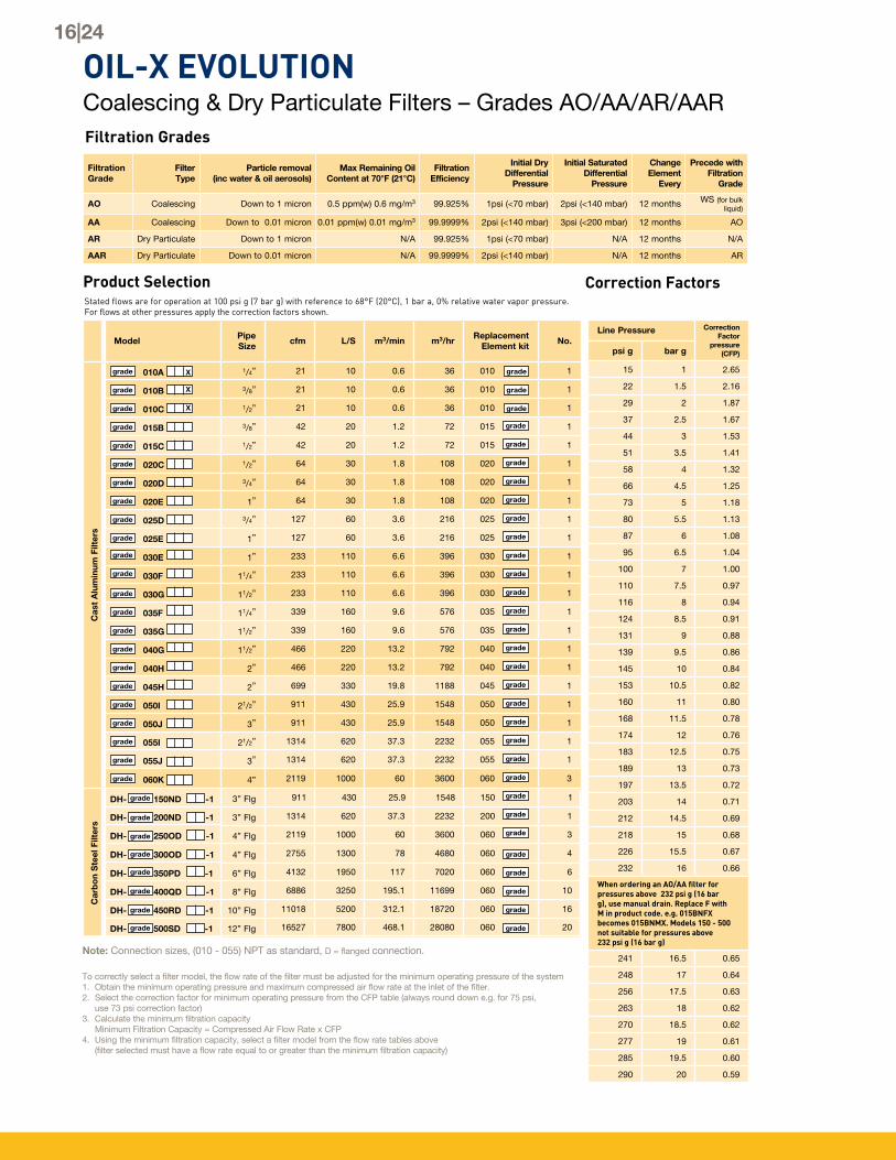
Product SelectionStated flows are for operation at 100 psi g (7 bar g) with reference to 68°F (20°C), 1 bar a, 0% relative water vapor pressure.
Model Pipe Size cfm L/S m3/min m3/hr
WS010ANFX-US 1/4” 21 10 0.6 36
WS010BNFX-US 3/8” 21 10 0.6 36
WS010CNFX-US 1/2” 21 10 0.6 36
WS015BNFX-US 3/8” 85 40 2.4 144
WS020CNFX-US 1/2” 85 40 2.4 144
WS020DNFX-US 3/4” 85 40 2.4 144
WS020ENFX-US 1” 85 40 2.4 144
WS025DNFX-US 3/4” 233 110 6.6 396
WS030ENFX-US 1” 233 110 6.6 396
WS030FNFX-US 11/4” 233 110 6.6 396
WS030GNFX-US 11/2” 233 110 6.6 396
WS035FNFX-US 11/4” 742 350 21 1260
WS040GNFX-US 11/2” 742 350 21 1260
WS045HNFX-US 2” 742 350 21 1260
WS055INFX-US 21/2” 1695 800 48 2880
WS055JNFX-US 3” 1695 800 48 2880
WS1000 4” 2119 1000 60 3600
DH-WSA800-F 3” Flg 1700 802 48.1 2888
DH-WSA1000-F 4” Flg 2100 991 59.5 3568
DH-WSA1800-F 6” Flg 3780 1784 107 6422
DH-WSA3000-F 8” Flg 6300 2973 178.4 10704
DH-WSA4800-F 10” Flg 10080 4757 285.4 17126
DH-WSA7200-F 12” Flg 15120 7136 428.2 25689
Cas
t A
lum
inum
Ran
ge
Car
bo
n S
teel
Ran
ge
Separation Performance (models WS010 - WS055)
Differential Pressure versus Flow (models WS010 - WS055)
To correctly select a filter model, the flow rate of the filter must be adjusted for the minimum operating pressure of the system.
1. Obtain the minimum operating pressure and maximum compressed air flow rate at the inlet of the filter.
2. Select the correction factor for minimum operating pressure from the CFP table (always round down e.g. for 75 psi, use 73 psi correction factor)
3. Calculate the minimum filtration capacity Minimum Filtration Capacity = Compressed Air Flow Rate x CFP
4. Using the minimum filtration capacity, select a water separator model from the flow rate tables above (water separator selected must have a flow rate equal to or greater than the minimum filtration capacity)
Correction Factors
Line Pressure Correction Factor pressure (CFP)psi g bar g
15 1 4.00
29 2 2.63
44 3 2.00
58 4 1.59
73 5 1.33
87 6 1.14
100 7 1.00
116 8 0.94
131 9 0.89
145 10 0.85
160 11 0.82
174 12 0.79
189 13 0.76
203 14 0.73
218 15 0.71
232 16 0.68
When ordering a WS filter for pressures above 232 psi g (16 bar g), use manual drain. Replace F with M in product code. e.g. 015BNFX becomes 015BNMX. Models 800F - 7200F not suitable for pressures above 232 psi g (16 bar g)
248 17 0.67
263 18 0.65
277 19 0.63
292 20 0.62
14|24
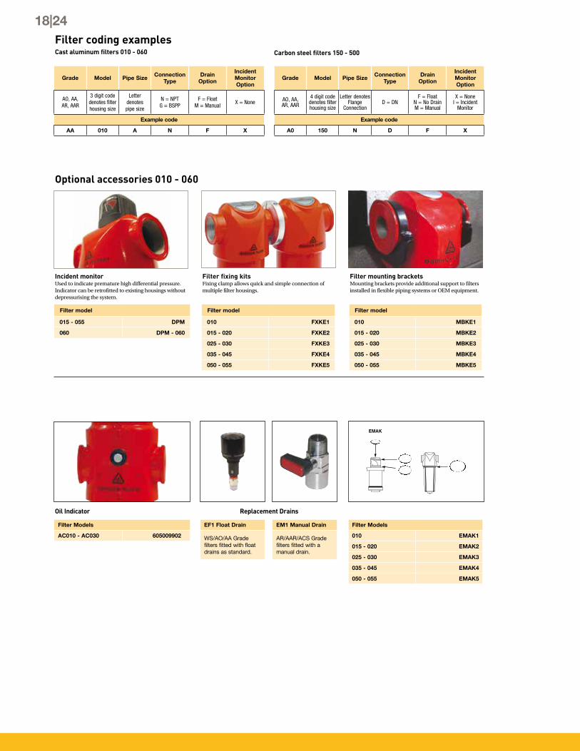
Water separator coding exampleWS010 - WS055
Grade ModelPipe Size
Connection Type
Drain Option
Incident Monitor Option
WS3 digit code denotes filter housing size
Letter denotespipe size
N = NPTG = BSPP
F = FloatM = Manual
X = None
Example code
WS 010 A N F X
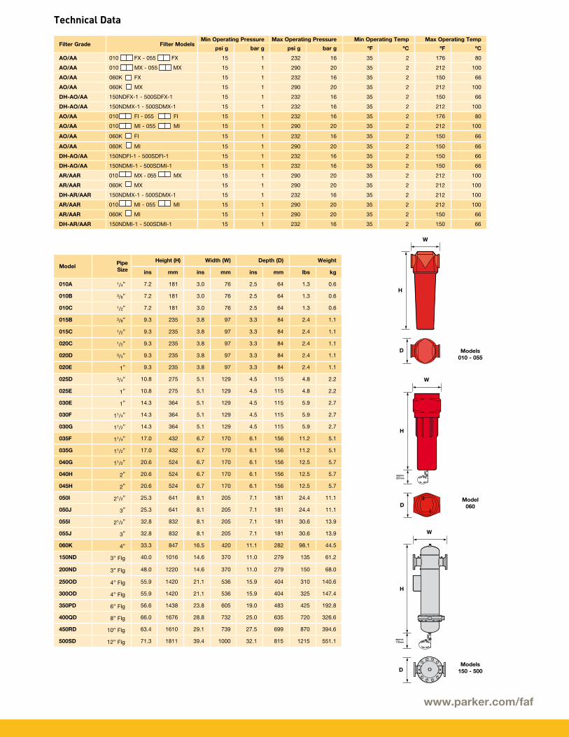
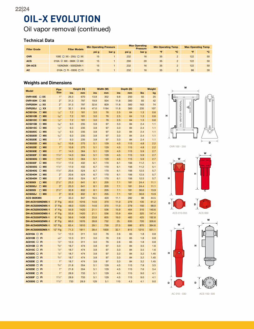
Weights and Dimensions
Technical Data
approx 227mm
approx 170mm
approx 170mm
approx 227mm
approx 170mm
approx 170mm
approx 170mm
Model Pipe SizeHeight (H) Width (W) Depth (D) Weight
Product SelectionStated flows are for operation at 100 psi g (7 bar g) with reference to 68°F (20°C), 1 bar a, 0% relative water vapor pressure. For flows at other pressures apply the correction factors shown.
Filtration Grades
Correction Factors
Filtration Grade
Filter Type
Particle removal (inc water & oil aerosols)
Max Remaining Oil Content at 70°F (21°C)
Filtration Efficiency
Initial Dry Differential
Pressure
Initial Saturated Differential
Pressure
Change Element
Every
Precede with Filtration
Grade
AO Coalescing Down to 1 micron 0.5 ppm(w) 0.6 mg/m3 99.925% 1psi (<70 mbar) 2psi (<140 mbar) 12 months WS (for bulk liquid)
AA Coalescing Down to 0.01 micron 0.01 ppm(w) 0.01 mg/m3 99.9999% 2psi (<140 mbar) 3psi (<200 mbar) 12 months AO
AR Dry Particulate Down to 1 micron N/A 99.925% 1psi (<70 mbar) N/A 12 months N/A
AAR Dry Particulate Down to 0.01 micron N/A 99.9999% 2psi (<140 mbar) N/A 12 months AR
Line Pressure Correction Factor
pressure (CFP)psi g bar g
15 1 2.65
22 1.5 2.16
29 2 1.87
37 2.5 1.67
44 3 1.53
51 3.5 1.41
58 4 1.32
66 4.5 1.25
73 5 1.18
80 5.5 1.13
87 6 1.08
95 6.5 1.04
100 7 1.00
110 7.5 0.97
116 8 0.94
124 8.5 0.91
131 9 0.88
139 9.5 0.86
145 10 0.84
153 10.5 0.82
160 11 0.80
168 11.5 0.78
174 12 0.76
183 12.5 0.75
189 13 0.73
197 13.5 0.72
203 14 0.71
212 14.5 0.69
218 15 0.68
226 15.5 0.67
232 16 0.66
When ordering an AO/AA filter for pressures above 232 psi g (16 bar g), use manual drain. Replace F with M in product code. e.g. 015BNFX becomes 015BNMX. Models 150 - 500 not suitable for pressures above 232 psi g (16 bar g)
Note: Connection sizes, (010 - 055) NPT as standard, D = flanged connection.
To correctly select a filter model, the flow rate of the filter must be adjusted for the minimum operating pressure of the system1. Obtain the minimum operating pressure and maximum compressed air flow rate at the inlet of the filter.2. Select the correction factor for minimum operating pressure from the CFP table (always round down e.g. for 75 psi, use 73 psi correction factor)3. Calculate the minimum filtration capacity Minimum Filtration Capacity = Compressed Air Flow Rate x CFP 4. Using the minimum filtration capacity, select a filter model from the flow rate tables above (filter selected must have a flow rate equal to or greater than the minimum filtration capacity)
Incident monitor Used to indicate premature high differential pressure. Indicator can be retrofitted to existing housings without depressurising the system.
Filter fixing kitsFixing clamp allows quick and simple connection of multiple filter housings.
Filter mounting brackets Mounting brackets provide additional support to filters installed in flexible piping systems or OEM equipment.
WS/AO/AA Grade filters fitted with float drains as standard.
EM1 Manual Drain
AR/AAR/ACS Grade filters fitted with a manual drain.
Filter Models
010 EMAK1
015 - 020 EMAK2
025 - 030 EMAK3
035 - 045 EMAK4
050 - 055 EMAK5
18|24
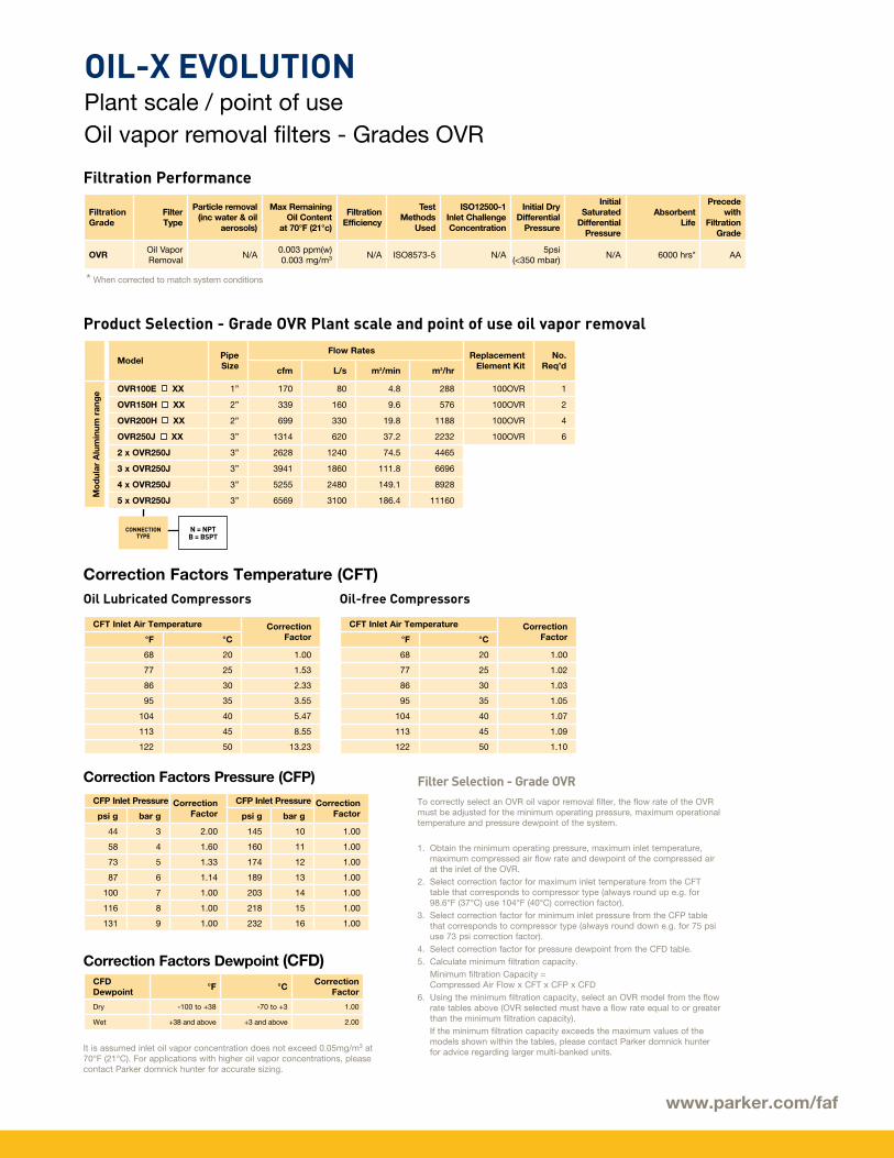
OIL-X EVOLUTIONPlant scale / point of useOil vapor removal filters - Grades OVR
CONNECTION TYPE
N = NPTB = BSPT
Product Selection - Grade OVR Plant scale and point of use oil vapor removal
ModelPipe Size
Flow Rates Replacement Element Kit
No. Req’dcfm L/s m3/min m3/hr
OVR100E XX 1” 170 80 4.8 288 100OVR 1
OVR150H XX 2” 339 160 9.6 576 100OVR 2
OVR200H XX 2” 699 330 19.8 1188 100OVR 4
OVR250J XX 3” 1314 620 37.2 2232 100OVR 6
2 x OVR250J 3” 2628 1240 74.5 4465
3 x OVR250J 3” 3941 1860 111.8 6696
4 x OVR250J 3” 5255 2480 149.1 8928
5 x OVR250J 3” 6569 3100 186.4 11160
CFT Inlet Air Temperature Correction Factor°F °C
68 20 1.00
77 25 1.53
86 30 2.33
95 35 3.55
104 40 5.47
113 45 8.55
122 50 13.23
Mo
dul
ar A
lum
inum
ran
ge
CFP Inlet Pressure Correction Factor
CFP Inlet Pressure Correction Factorpsi g bar g psi g bar g
44 3 2.00 145 10 1.00
58 4 1.60 160 11 1.00
73 5 1.33 174 12 1.00
87 6 1.14 189 13 1.00
100 7 1.00 203 14 1.00
116 8 1.00 218 15 1.00
131 9 1.00 232 16 1.00
It is assumed inlet oil vapor concentration does not exceed 0.05mg/m3 at 70°F (21°C). For applications with higher oil vapor concentrations, please contact Parker domnick hunter for accurate sizing.
Filter Selection - Grade OVRTo correctly select an OVR oil vapor removal filter, the flow rate of the OVR must be adjusted for the minimum operating pressure, maximum operational temperature and pressure dewpoint of the system.
1. Obtain the minimum operating pressure, maximum inlet temperature, maximum compressed air flow rate and dewpoint of the compressed air at the inlet of the OVR.
2. Select correction factor for maximum inlet temperature from the CFT table that corresponds to compressor type (always round up e.g. for 98.6°F (37°C) use 104°F (40°C) correction factor).
3. Select correction factor for minimum inlet pressure from the CFP table that corresponds to compressor type (always round down e.g. for 75 psi use 73 psi correction factor).
4. Select correction factor for pressure dewpoint from the CFD table.5. Calculate minimum filtration capacity. Minimum filtration Capacity =
Compressed Air Flow x CFT x CFP x CFD6. Using the minimum filtration capacity, select an OVR model from the flow
rate tables above (OVR selected must have a flow rate equal to or greater than the minimum filtration capacity).
If the minimum filtration capacity exceeds the maximum values of the models shown within the tables, please contact Parker domnick hunter for advice regarding larger multi-banked units.
CFD Dewpoint
°F °CCorrection
Factor
Dry -100 to +38 -70 to +3 1.00
Wet +38 and above +3 and above 2.00
CFT Inlet Air Temperature Correction Factor°F °C
68 20 1.00
77 25 1.02
86 30 1.03
95 35 1.05
104 40 1.07
113 45 1.09
122 50 1.10
Filtration Performance
Oil Lubricated Compressors
Correction Factors Temperature (CFT)
Correction Factors Pressure (CFP)
Correction Factors Dewpoint (CFD)
Oil-free Compressors
Filtration Grade
Filter Type
Particle removal (inc water & oil
aerosols)
Max Remaining Oil Content
at 70°F (21°c)
Filtration Efficiency
Test Methods
Used
ISO12500-1 Inlet Challenge Concentration
Initial Dry Differential
Pressure
Initial Saturated
Differential Pressure
Absorbent Life
Precede with
Filtration Grade
OVROil Vapor Removal
N/A0.003 ppm(w)0.003 mg/m3 N/A ISO8573-5 N/A
5psi(<350 mbar)
N/A 6000 hrs* AA
* When corrected to match system conditions
www.parker.com/faf
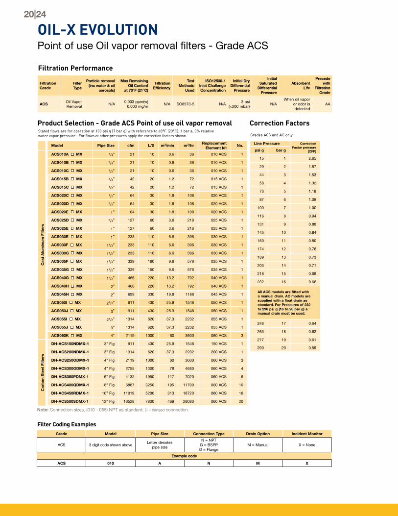
Product Selection - Grade ACS Point of use oil vapor removalStated flows are for operation at 100 psi g (7 bar g) with reference to 68°F (20°C), 1 bar a, 0% relative water vapor pressure. For flows at other pressures apply the correction factors shown. Grades ACS and AC only
Correction Factors
Line Pressure Correction Factor pressure
(CFP)psi g bar g
15 1 2.65
29 2 1.87
44 3 1.53
58 4 1.32
73 5 1.18
87 6 1.08
100 7 1.00
116 8 0.94
131 9 0.88
145 10 0.84
160 11 0.80
174 12 0.76
189 13 0.73
203 14 0.71
218 15 0.68
232 16 0.66
All ACS models are fitted with a manual drain. AC models are supplied with a float drain as standard. For Pressures of 232 to 290 psi g (16 to 20 bar g) a manual drain must be used.
Product Selection - Grade AC point of use oil vapor removal
Cas
t A
lum
inum
Filt
ers
To correctly select a filter model, the flow rate of the filter must be adjusted for the minimum operating pressure of the system
1. Obtain the minimum operating pressure and maximum compressed air flow rate at the inlet of the filter.
2. Select the correction factor for minimum operating pressure from the CFP table (always round down e.g. for 75 psi, use 73 psi correction factor)
3. Calculate the minimum filtration capacity Minimum Filtration Capacity = Compressed Air Flow Rate x CFP
4. Using the minimum filtration capacity, select a filter model from the flow rate tables above (filter selected must have a flow rate equal to or greater than the minimum filtration capacity)
AC models are supplied with a float drain as standard. For Pressures of 232 to 290 psi g (16 to 20 bar g) a manual drain must be used.
Ref: Accessories - EM1
Filter Coding ExamplesAC010 - 030
Grade Model Pipe Size Connection Type Drain Type Bulk Oil Indicator
AftermarketCompressed air equipment users demand much more than the supply of high quality products in order to maintain a competitive edge.
Modern production technology is increasingly demanding the provision of a higher purity and more reliable compressed air supply. Products and solutions that are manufactured by Parker domnick hunter are designed to provide air quality that meets with and often exceeds international standards.
As well as the requirement for air purity and reliability, there are additional factors to consider when choosing the right service provider for your compressed air and gas purification system. For example, knowledge of the many regulations regarding the management of industrial waste, energy efficiency improvement programs and consideration of any environmental impact. It is anticipated that future legislations will demand further in-depth technical and knowledge-based support from service providers.
Our commitment to industry does not stop with the supply of
high quality products. We are also committed to ensuring that our equipment provides high performance by providing a trouble-free service from a bespoke maintenance and verification package – all tailored to your own specific requirements.
We offer a wide range of valuable services that will impact positively on your drive towards improved production efficiency and product quality with reduced production rejections and operational costs.
From initial selection to installation, commissioning, preventative maintenance and specialized services, Parker domnick hunter is redefining customer service.
Filter Elements and Consumable Parts
Maintenance, Repair and Overhaul
Customer Support Specialised Services
Genuine Replacement filter elements
Preventative Maintenance Kits
Repair Kits
Installation Kits
Upgrade Kits
Installation and Commissioning
Maintenance and Repair
Updates and Upgrades
Service Contracts
Parts Service
Warranty
Business Development
Technical Support Group
Training
Technical Publications
Air Quality Testing
Dewpoint Measurement
Leak Detection
Particle Counting
Micro-biological Testing
www.parker.com/faf
North AmericaCompressed Air TreatmentFiltration & Separation/BalstonHaverhill, MA 978 858 0505 www.parker.com/balston
Finite Airtek Filtration Airtek/domnick hunter/ZanderLancaster, NY 716 686 6400 www.parker.com/faf
Finite Airtek Filtration/FiniteOxford, MI 248 628 6400 www.parker.com/finitefilter
Engine Filtration & Water PurificationRacor Modesto, CA 209 521 7860 www.parker.com/racor
Holly Springs, MS 662 252 2656 www.parker.com/racor
Beaufort, SC 843 846 3200 www.parker.com/racor
Racor – Village Marine Tec.Gardena, CA 310 516 9911 desalination.parker.com
Parker Sea RecoveryCarson, CA 310 637 3400 www.searecovery.com