Fifth Committee Draft (5CD) Date: May 2016 Reference number: OIML TC 9/SC 2/R 61-2 5CD Partially supersedes: OIML R 61-1 Automatic gravimetric filling instruments Edition 2004 (E) OIML TC 9/TC 2 Automatic weighing instruments p 8 Revision of R 61 Automatic gravimetric filling instruments TITLE OF THE CD (English): OIML R 61 Automatic gravimetric filling instruments Part 2: Test procedures TITLE OF THE CD (French): OIML R 61 Doseuses pondérales à fonctionnement automatique Partie 2: Procédures d’essais Original version in: English
PART 2 – Test methodsprocedures 1 Introduction 2 Scope 3. Terms and definitions …………………………….. 4. Symbols, units and equations 5. Examination for type evaluation 5.1 Documentation 5.2 Compare construction with documentation 5.3 Metrological requirements 5.4 Technical requirements 5.5 Functional requirements 6. Examination for initial verification 6.1 Compare construction with documentation 6.2 Descriptive markings 7. General test requirements 7.1 Power supply 7.2 Zero-setting 7.3 Temprature 7.4 Recovery 7.5 Pre-loading 7.6 Control instruments 7.7 Indication of a digit smaller than d 7.8 Test program 8. Test programmmethods 8.1 Type evaluationDetermination of mass of individual fills 8.2 Place of testing for type evaluationConducting material tests 8.3 Non-automatic weighing instrumentsNumber of fills 8.4 Initial verificationAccuracy of standards 8.5 Material test methods 8.6 Preset value 8.7 Mass and average value of the test fills 8.8 Deviation for automatic weighing 8.9 Preset value error for automatic weighing 9. Static tests (type evaluation stage) 9.1 General 9.2 Performance tests 9.32 Zero-setting and tare devices 9.43 Static weighing test method for type evaluation 9.54 Determination of reference accuracy class, Rex(x) 10. Influence factor and disturbance tetsts 10.1 Test conditions
10.2 Influence factor tests ……… …………………
10.2.1 Warm-up time 10.2.2 Temperature with static load 10.2.3 Temperature effect on no-load indication 10.2.4 Damp heat, steady state test 10.2.5 AC mains voltage variation 10.2.6 DC mains voltage variation 10.2.7 Low voltage of internal battery (not connected to mains power) 10.2.8 Power from external 12 V and 24 V road vehicle batteries 10.2.9 Tilting 10.3 Disturbance tests 10.3.1 Damp heat, cyclic test 10.3.210.3.1 AC mains voltage dips, short interruptions and reductions 10.3.310.3.2 Bursts (fast transient tests) on mains power lines and on signal, data and control lines 10.3.410.3.3 Electrostatic discharge 10.3.510.3.4 Immunity to electromagnetic fields 10.3.610.3.5 Surges on AC and DC mains power lines and on signal, data and control lines 10.3.710.3.6 Electrical transient conduction for AFGIinstruments powered by 12 V and 24 V batteries 10.3.7 Ripple on DC mains power 10.3.910.3.8 Battery voltage variations during starting up a vehicle engine 10.3.1010.3.9 Load dump test 10.3.1110.3.10 DC mains voltage dips, short interruptions and (short term) variations
R 61-2 Page 3
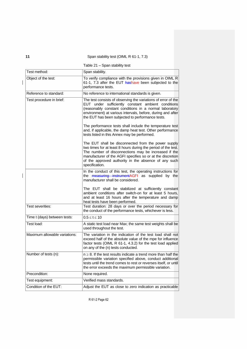
11 Span stability test 12 Procedure for material tests 12.1 Material tests at type evaluation 12.2 Material tests at initial verification Annex A Error calculation for multi-load filling AFGIAGFIs (Mandatory) A.1 Fault limit for multi-load AGFIs A.2 Influence factor tests mpes for multi-load AGFIs Annex B Equipment Under Test (Informative) B.1 Selection of EUTs B.2 Other metrological features to be considered Annex C Metrological Control (Informative) Annex D Considerations on rated minimum fill (MinFill) (Informative) Annex E Conversion of NAWI (Indicator) Test results for AWI purposes
The International Organization of Legal Metrology (OIML) is a worldwide, intergovernmental organization whose primary aim is to harmonize the regulations and metrological controls applied by the national metrological services, or related organizations, of its Member States. The main categories of OIML publications are:
International Recommendations (OIML R), which are model regulations that establish the
metrological characteristics required of certain measuring instruments and which specify methods and equipment for checking their conformity. OIML Member States shall implement these Recommendations to the greatest possible extent;
International Documents (OIML D), which are informative in nature and which are intended to
harmonize and improve work in the field of legal metrology;
International Guides (OIML G), which are also informative in nature and which are intended to
give guidelines for the application of certain requirements to legal metrology; and
International Basic Publications (OIML B), which define the operating rules of the various
OIML structures and systems. OIML Draft Recommendations, Documents and Guides are developed by Technical Committees or Subcommittees which comprise representatives from the Member States. Certain international and regional institutions also participate on a consultation basis. Cooperative agreements have been established between the OIML and certain institutions, such as ISO and the IEC, with the objective of avoiding contradictory requirements. Consequently, manufacturers and users of measuring instruments, test laboratories, etc. may simultaneously apply OIML publications and those of other institutions.
International Recommendations, Documents, Guides and Basic Publications are published in English (E) and translated into French (F) and are subject to periodic revision.
Additionally, the OIML publishes or participates in the publication of Vocabularies (OIML V) and periodically commissions legal metrology experts to write Expert Reports (OIML E). Expert Reports are intended to provide information and advice, and are written solely from the viewpoint of their author, without the involvement of a Technical Committee or Subcommittee, nor that of the International Committee of Legal Metrology. Thus, they do not necessarily represent the views of the OIML.
This publication - reference OIML R 61-1 and -2, Edition XXX - was developed by Technical Subcommittee TC 9/SC 2 Automatic weighing instruments. It was approved for final publication by the International Committee of Legal Metrology in XXX and will be submitted to the International Conference of Legal Metrology in XXX for formal sanction. It supersedes the previous edition of R 61-1 (2004).
OIML Publications may be downloaded from the OIML web site in the form of PDF files. Additional information on OIML Publications may be obtained from the Organization’s headquarters:
Bureau International de Métrologie Légale 11, rue Turgot - 75009 Paris - France
Part 2 – Test procedures 1 Introduction This OIML Recommendation consists of 3 separate parts: Part 1: Metrological and Technical Requirements , Part 2: Test procedures, Part 3: Report Format for Type Evaluation
2 Scope This part of OIML R 61 (OIML R 61-2:xxx) is applicable to the type evaluation and initial verification testing of for automatic gravimetric filling instruments (hereafter referred to as “AGFI(s)”), as defined in 3.2.2 in OIML R 61-1:xxx. OIML R 61 sets out details of the test program, principles, equipment and procedures to be used for type evaluation and initial verification testing. OIML Certificates of Conformity can be issued for automatic gravimetric filling instruments under the scope of the OIML Certificate System, provided that this part of OIML R 61, OIML R 61-1:xxx and OIML R 61-3:xxx are used in accordance with the rules of the System. The provisions of this part of OIML R 61 also apply to ancillary devices, if required by national regulations.
3 Terms and definitions For the purposes of OIML R 61, the terms and definitions given in clause 3 of OIML R 61-1, 3 apply.
4 Symbols, units and equations Symbols used in this part of OIML R 61, are defined in OIML R 61-1, 3.8. 5 Examination for type evaluation 5.1 Documentation Review the documentation that is submitted to determine if it is adequate and correct. For type evaluation the documentation shall be as specified in OIML R 61-1, 8.2.1. 5.2 Compare construction with documentation
R 61-2 Page 7
Examine the various devices of the AGFI to ensure compliance with the documentation in accordance with OIML R 61-1, 5 and 8.2.1.
5.3 Metrological requirements Record the metrological characteristics using the checklist in the report format for type evaluation OIML R 61-3. 5.4 Technical requirements Examine the AGFI for conformity with the technical requirements according to OIML R 61-1, 5, using the checklist in the report format for type evaluation OIML R 61-3. 5.5 Functional requirements Examine the AGFI for conformity with functional requirements according to OIML R 61-1, 6 and 7, using the checklist in the report format for type evaluation OIML R 61-3 and in accordance with the test program in 5.6. 6 Examination for initial verification 6.1 Compare construction with documentation Examine the AGFI for conformity with the approved type according to OIML R 61-1, 8.3.1. 6.2 Descriptive markings Check the descriptive markings in accordance with OIML R 61-1, 5.12, using the checklist in the report format for type evaluation OIML R 61-3.
7 General test requirements
7.1 Power supply (OIML R 61-1, 4.8.3) Power up the equipment under test (EUT) for a time period equal to or greater than the warm-up time specified by the manufacturer and maintain the EUT energised for the duration of each test. 7.2 Zero-setting (OIML R 61-1, 5.8) Using the manual or semi-automatic zero-setting facility, adjust the EUT as closely as practicable to zero prior to each test, and do not readjust it at any time during the test, except to reset if a significant fault has been indicated. Status of automatic zero devices shall be as specified for each test. 7.3 Temperature (OIML R 61-1, 4.8.2)
R 61-2 Page 8
The tests shall be performed at a steady ambient temperature, usually normal ambient temperature unless otherwise specified. The temperature is deemed to be steady when the difference between the extreme temperatures noted during the test does not exceed
one-fifth of the temperature range of the AGFI without being greater than 5 C, and the
rate of change does not exceed 5 C per hour. The handling of the AGFI shall not result in condensation of water on the AGFI.
7.4 Recovery After each test the AGFI shall be allowed to recover sufficiently before the next test.
7.5 Pre-loading Before each static and influence factor test the AGFI shall be pre-loaded once to Max, except for the tests in 10.2.1 (warm-up time) and 10.2.3 (temperature effect on no-load). 7.6 Control instruments (OIML R 61-1, 3.2.2.4 and 5.13.3) 7.6.1 Accuracy of test system (8.2.4) Weighing systems for performing the tests with actual products (material tests) which include the control instrument and standard weights used for weighing the test loads and fills are required not to have an error exceeding one third of the mpd and mpse (as appropriate) of for the AGFI in accordance with 8.2.4 and 8.2.5OIML R 61-1, 4.3.2 and 4.3.3.
Note: Accuracy requirements for the test system depend on the error limitation which depends on the accuracy class. However the class is determined from the results of the tests. It is therefore necessary that the metrological authority responsible for testing should be informed of the best accuracy class that may be achieved, prior to commencement of testing.
7.6.2 Use of standard weights to assess rounding error of indication 7.6.2.1 General method to assess error of indication prior to rounding For AFGIAGFIs with digital indication having a scale interval d, changeover points may be used to interpolate between scale intervals i.e. to determine the indication of the instrument, prior to rounding, as follows. At a certain load, L, the indicated value, I, is noted. Additional weights of say 0.1 d are successively added until the indication of the AGFI is increased unambiguously by one scale interval (I + d). The additional load ΔL added to the load receptor gives the indication, P, prior to rounding by using the following formula: P = I + 0.5 d - ΔL The error prior to rounding is: E = P - L = I + 0.5 d - ΔL - L Example: An AFGIAGFI with a scale interval, d, of = 5 g is loaded with 1 kg and thereby indicates 1 000 g. After adding successive weights of 0.5 g, the indication changes from 1 000 g to 1 005 g at an additional load of 1.5 g. Inserted in the above formula these observations give:
R 61-2 Page 9
P = (1 000 + 2.5 - 1.5) g = 1 001 g Thus the true indication prior to rounding is 1 001 g, and the error of indication prior to rounding is: E = (1 001 - 1 000) g = +1 g 7.6.2.2 Correction for error at zero Evaluate the error at zero load, (E0) by the method of 7.6.2.1. Evaluate the error at load L, (E) by the method of 7.6.2.1 The corrected error prior to rounding, (Ec) is: Ec = E - E0 For the example in 7.6.2.1, the error calculated at zero load was: E0 = +0.5 g, the corrected error is: Ec = + 1 - (+ 0.5) = +0.5 Zero-tracking has to be switched off or procedure as per 9.2.3.2 “note” has to be followed. 7.7 Indication of a digit smaller than d
If an AFGIAGFI with digital indication has a device for displaying temporarily the indication with a smaller scale interval (not greater than 0.2 d), this device may be used to determine the error. If a device is used, it should be noted in the Test Report.
Note: Such indication is only for test purposes. 7.8 Test program 7.8.1 Type evaluation (OIML R 61-1, 8.2.2 and 8.2.3) The following tests shall normally be applied for type evaluation:
a) Examination for type evaluation in 5, b) Static tests in 9, c) Influence factor and disturbance tests in 10, d) Span stability test in 11, and e) Material tests in 12.1
7.8.2 PlaceLocation of testing for type evaluation AGFIs submitted for type evaluation may be tested either:
a) On the premises of the metrological authority to which the application has been submitted, or
b) In any other suitable placelocation agreed between the metrological authority concerned and the applicant.
R 61-2 Page 10
7.8.3 Non-automatic weighing instruments (OIML R 61-1, 23.6.1) If the weighing function is provided by a non-automatic weighing instrument that has been approved in respect of conformity with OIML R 76 [6], the tests specified in 7.8.1 (except 12.1) may be omitted where equivalent test results specified in OIML R 76 [6] prove conformity with the relevant parts of OIML R 61. Use of OIML R 76 [6] test results shall be recorded in the test report checklist and summary in OIML R 61-3. 7.8.4 Initial verification (OIML R 61-1, 8.3) The following tests shall normally be applied for initial verification:
a) Examination for initial verification in 6, and b) Material tests at initial verification in 12.2.
Static weighing test method (9.3) may also be used if necessary to verify the indicator for the integral verification method of material tests. If the AGFI is liable to be tilted or is not fitted with a levelling device and a level indicator, the test in 10.2.9 shall also be performed.
R 61-2 Page 11
8 Test methods 8.1 Determination of the mass of individual fills The mass of individual fills is determined using either the separate verification method in 8.5.1 or the integral verification method in 8.5.2. 8.2 Conducting of material tests
8.2.1 Values of the mass of the fills
a) The tests shall be carried out on using fills with representing loads at, or near to, the Max and also at, or near to, the Minfill of the AGFI, and if Min is different from Minfill fills with loads at, or near to Min.
b) Cumulative weighers shall be tested as in a) with the maximum practical number of loads per fill and also with the minimum number of loads per fill, and associativeselective combination weighers with the average (or optimum) number of loads per fill (R 61.1, 3.4.10).
c) If the Minfill is less than one third of the Maxfill then tests shall also be carried out at a value near the centre of the load weighing range, at values close to, but not above, 100 g, 300 g, 1 000 g or 15 000 g, as appropriate.
Note: Test fills for some values defined here above may be impossible to obtain
or use due to particular conditions on packing lines. Such conditions and the impossibility to perform the test shall be documented and reported on corresponding test or evaluation reports.
8.2.2 Type of materials for the test loads
For type evaluation, the materials used for test loads shall be representative of a product for which the AGFI is designed (R 61-1, 8.2.3.1) and for initial verification and in-service material used for test loads shall be products for which the AGFI is intended (R 61-1, 8.3.2). 8.2.3 Condition Conducting of tests All tests shall be conducted with any adjustable parameter critical to metrological integrity, e.g. final feed time or rate, set to the most onerous condition allowed by the manufacturer’s printed instructions and incorporated in the descriptive markings. Prior to the start of a new test the AGFI shall be operated for a time period under normal operating conditions to enable stability, i.e until all the principal parts, devices and parameters such as warm-up, temperature, indications, etc, critical to metrological integrity have stabilized according to the manufacturer’s printed instructions. During this stabilization period the fills shall not be included in the test. Any correction device, e.g. material flow correction, automatic zero-setting fitted to an AGFI, etc shall be operated during the tests according to the manufacturer’s printed instructions. The initial fills after the change between Max and Min shall be included in the test unless the AGFI bears a clear warning to discard the stated number of fills after a change to the AGFI’s settings.
R 61-2 Page 12
8.3 Number of fills The minimum number of individual test fills depends upon the preset value (FP) as specified in Table 1.
Table 1- Number of test fills
Preset value of the fills FP (kg)
Minimum number of test fills (n)
< FP 1 kg 60 fills
1 kg < FP 10 kg 30 fills
10 kg < FP 25 kg 20 fills
25 kg < FP 10 fills
Where 2 or more AGFIs are integrated in a carousel, the maximum number of test fills shall be the greatest of either:
a) 4xN, or b) the values given in Table 1.
where N is the number of filling s tations in the machine. 8.4 Accuracy of standards The control instrument and standard weights used in testing shall ensure the checking of the test fills to an error not greater than one third of the mpd and mpse (as appropriate) for automatic weighing (see OIML R 61-1, 4.3.2 and 4.3.3). Note: It is advised to verify the correct and adequate operation of the control instrument
or the device used for control purposes prior to executing the material test 8.5 Material test methods 8.5.1 Separate verification method The separate verification method requires the use of a (separate) control instrument (details as given in 7.6, and OIML R 61-1, 5.13.33.2.2.4) to find the conventional value of the mass of the test fill. 8.5.2 Integral verification method With this method the AGFI being tested is used to determine the conventional value of the mass of the test fill. The integral verification method shall be conducted using either:
a) An appropriately designed indicating device, or
b) An indicating device with standard weights to assess the rounding error.
Note 1: The integral verification method depends on determining the mass of the loads.
The error limits (OIML R 61-1, 4.3) are for the mass of the fill. If it is not possible
R 61-2 Page 13
to ensure that in normal operation all the load is discharged at each cycle of operation, i.e. that the sum of the loads is equal to the fill, then the separate verification method (8.5.1) must be used.
Note 2: When using the integral verification method for a cumulative weighing instrument a sub-division of the test fill is unavoidable. When calculating the conventional value of the mass of the test fill, it is necessary to consider the increased uncertainty due to the division of the test fill.
8.5.2.1 Interruption of automatic filling operation An automatic filling operation of a test fill shall be initiated as for normal operation. However the automatic operation shall be interrupted twice during each filling cycle in the following conditions: a) on the AGFI where the fill is weighed in the load receptor
after filling the load receptor (1)
after discharge of the load receptor (2)
b) on the AGFI where the load is weighed in a container on the load receptor
after tare balancing the empty container (2)
after filling the container (1)
c) on a subtractive weigher
after tare balancing the filled load receptor (1)
after discharge of the fill from the load receptor (2)
An automatic filling operation shall not be interrupted during consecutive weighing cycles if the interruption would significantly affect the mass of the fill. In this case, one or two fills shall be discharged in automatic operation without being checked, between the fills that are checked.
(1) Pre-discharge (full) interrupt The automatic operation shall be interrupted immediately after the feed of material has ceased and the load receptor(s), or the container on the load receptor has been filled, or on a subtractive weigher the filled load receptor has been tare balanced. When the load receptor(s) has (have) stabilized, the net weight of the fill indicated or determined by balancing with standard weights shall be recorded and the AGFI switched back to automatic operation.
(2) Post-discharge (empty) interrupt The automatic operation shall be interrupted after the load(s) has (have) been discharged, or a new container has been placed on the load receptor and its weight has been tare balanced, and the load receptor(s) is (are) ready to receive a further load. When the load receptor(s) has (have) stabilized, the empty load receptor weight indicated or determined by balancing with standard weights shall be recorded and the AGFI switched back to automatic operation. 8.6 Preset value The indicated preset value of the average and deviation fill shall be noted where applicableif applicable. 8.7 Mass and average mass value of the test fills
R 61-2 Page 14
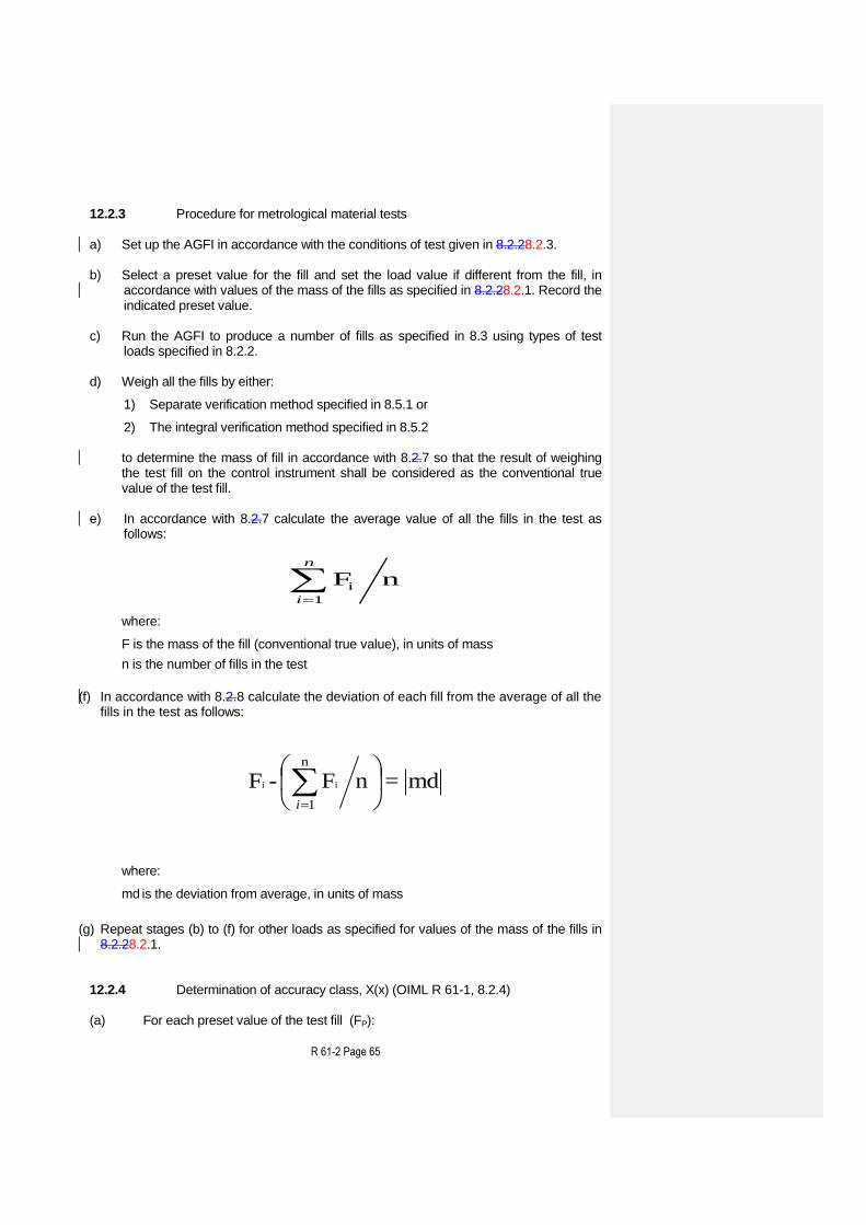
The test fill shall be weighed on a control instrument and the result shall be considered as being the conventional mass value of the test fill. The average value of all the test fills shall be calculated and noted. 8.8 Deviation for automatic weighing The deviation for automatic weighing used to determine compliance of each fill with the maximum permissible deviation for automatic weighing (OIML R 61-1, 4.3.1) shall be the difference between the conventional value of the mass of the test fill (8.7) and the average value of all the fills in the test. 8.9 Preset value error for automatic weighing The preset value error for automatic weighing used to determine compliance with OIML R 61-1, 4.3.3 shall be the difference between the average value of the conventional mass value of the test fills (8.7) and the preset value of the fills.
R 61-2 Page 15
9 Static tests (type evaluation stage) 9.1 General (OIML R 61-1, 8.2.2 and 8.2.3.2) AFGIAGFIs or instrument simulators are required to have a load indicator, or an interface allowing access to a quantity that can be adjusted to provide an indication of load so that the effect of influence quantities may be tested and the reference accuracy class determined. This facility also enables testing of warm-up time and zero-setting and tare devices where applicableif applicable. The static weighing tests are normally done as part of influence quantity testing. The limits of error for warm-up time tests and the accuracy of zero- and tare-setting tests (OIML R 61-1, 4.3) are evaluated after Ref(x) has been determined (OIML R 61-1, 8.2.58.2.4). 9.2 Zero-setting and tare devices (OIML R 61-1, 5.8) 9.2.1 General Zero and tare functions shall be tested separately unless it is proven that the same hardware and software routines are involved. Zero-setting and taring may be by more than one mode, for example:
a) Nonautomatic or semi-automatic, b) Automatic at switch-on, c) Automatic at start of automatic operation, d) Automatic at programmable time intervals, e) Automatic as part of weighing cycle. It is normally only necessary to test the accuracy of zero-setting and taring in one mode if it is clear that the same process is used for each mode. If zero-setting or taring is set as part of the automatic weighing cycle then this mode shall be tested. To test automatic zero-setting or taring it is necessary to allow the AGFI to operate through the appropriate part of the automatic cycle and then to halt the AGFI before testing. The range and accuracy of zero-setting shall be tested by applying loads as specified below in nonautomatic (static) operation to the load receptor after the AGFI is halted.
9.2.2 Range of zero-setting
9.2.2.1 Initial zero-setting (a) Positive range With the load receptor empty, set the AGFI to zero by switching it off and on. Place a test load on the load receptor and set the AGFI to zero again. Continue this process until it does not reset to zero. The maximum load that can be re-zeroed is the positive portion of the initial zero-setting range.
R 61-2 Page 16
(b) Negative range 1) Remove any load from the load receptor and set the AGFI to zero. Then, if
possible, remove any non-essential components of the load receptor. If, at this point, the AGFI can be reset to zero by switching the AGFI off and onwith the zero setting device, the mass of the non-essential components is used as the negative portion of the initial zero-setting range.
2) If the AGFI cannot be reset to zero with the non-essential components removed, add loads to any live part of the scale until the AGFI indicates zero again.
3) Then remove the loads and, after each load is removed, reset to zero by switching the AGFI off and on. The maximum load that can be removed while the AGFI can still be reset to zero is the negative portion of the initial zero-setting range.
4) The initial zero-setting range is the sum of the positive and negative portions. 5) Alternatively, if it is not possible to test the negative range of initial zero setting by
removing parts of the AGFI, the instrument may be temporarily re-adjusted with a test load applied before step (3) above. (The test load applied for the temporary re-adjustment should be greater than the permissible negative portion of the initial zero setting range which can be calculated from the result of the positive range test).
6) If it is not possible to test the negative portion of the initial zero-setting range by these methods then only the positive part of the zero-setting range need be considered.
7) Reassemble or re-adjust the AGFI for normal use after the above tests.
9.2.2.2 Automatic zero-setting range Remove the non-essential parts of the load receptor or re-adjust the AGFI as described in 9.2.2.1 and place weights on the live part of the scale until it indicates zero. Remove weights in small amounts and after each weight is removed allow the AGFI to operate through the appropriate part of the automatic cycle so as to see if the AGFI is reset to zero automatically. The maximum load that can be removed so the AGFI can still be reset to zero is the zero-setting range. 9.2.3 Accuracy of zero-setting and taring 9.2.3.1 Accuracy of zero-setting a) When the load receptor is empty, zero the AGFI in a mode as determined by 9.2.1. b) Add load(s) to the load receptor to determine the additional load at which the
indication changes from zero to one scale interval above zero. c) Calculate the error at zero according to the method described in 7.6.2.1. d) Verify that the zero-setting error is within the limit specified in OIML R 61-1, 5.8.2
Note: The zero tracking device shall be switched off or made inactive. The latter may
be achieved e.g. by loading with 10 d. Then the additional load at which the indication changes from one scale interval to the next above is determined and the error is calculated according to the description in 7.6.2.1. It is assumed that the error at zero load would be equal to the error at the load in question.
R 61-2 Page 17
9.2.3.2 Accuracy of zero-setting at taring tare The weighing tests should be performed on instruments with subtractive tare: with one tare value at 2/3 of maximum tare.Accuracy of the tare device shall be tested at the maximum tare as specified by the manufacturer.
a) Place the maximum tare load on the load receptor, operate the tare function key immediately in a mode as determined by 9.2.1 to enable the equilibrium device to release the tare function.
b) Add load(s) to the load receptor to determine the additional load at which the indication changes from zero to one scale interval above zero.
c) Calculate the error according to the method described in 7.6.2.1. d) Verify that the zero-setting error is within the limit specified in OIML R 61-1,
5.8.2 Note: The zero tracking device shall be switched off or made inactive. The latter may
be achieved e.g. by loading with 10 d. Then the additional load at which the indication changes from one scale interval to the next above is determined and the error is calculated according to the description in 7.6.2.1. It is assumed that the error at zero load would be equal to the error at the load in question
9.3 Static weighing test method for type evaluation (OIML R 61-1, 8.2.3) Apply test loads from zero up to and including Max, and similarly remove the test loads back to zero. The test loads selected shall include values close to Max and Min and other critical loads as specified in 9.2.2.18.2.1 c, subject to requirements of this Recommendation. Determine the error at each test load, using the standard weights assessment procedure of 7.6.2, if necessary, to obtain the accuracy of the test system as specified in 7.6.1. It should be noted that when loading or unloading, the load shall be progressively increased or progressively decreased. 9.4 Determination of reference accuracy class, Ref(x) (OIML R 61-1, 8.2.4) The static weighing tests during application of influence factors (as appropriate) shall be used at type evaluation stage to establish the reference value for accuracy class, i.e. Ref(x), as follows: a) Perform static weighing tests for influence factors and loads as specified in this
RecommendationOIML R 61. b) Determine the mpe for influence factor tests for class X(1), mpe(1) for each load as
follows:
mpe(1) = 0.25 mpd(1) x (pi, if applicable) in-service for the fill value equal to the
load. For example, with a load of 10 kg, the mpe for influence factor tests as specified in OIML R 61-1, 4.3.2 will be calculated thus:
R 61-2 Page 18
mpe(1) = pi x 0.25 x 1.5x 10^-2 x 10 kg = pi x 37.5 gmpe (1) = pi x (0.25 x 1.5 % x 10,000 g)
where
pi (as specified in OIML R 61-1, 8.2.3.3) is a fraction of the mpe applied to a part of the AGFI which is examined seperately
c) (Calculate [│Error│ / mpe(1)] for each load where: Error is the error corrected for the error at zero load (see 7.6.2.2). d) From (c) determine the maximum value of [│Error│ / mpe(1)] for all the influence
factor tests,
i.e., [│Error│ / mpe(1)]Max for all influence factor tests
e) Determine Ref(x) such that:
x [│Error│ / mpe(1)]Max and Ref(x) = 1 x 10k, 2 x 10k, or 5 x 10k,
the index k being a positive or negative whole number or zero. Fault limit values shall then be calculated from the mpd for the reference class (OIML R 61-1, Table 2).
R 61-2 Page 19
10 Influence factor and disturbance tests 10.1 Test conditions 10.1.1 General requirements Prior to a test, the error at zero shall be assessed and corrected by the methods given in 7.6.2 and in 7.6.2.2. Influence factor (OIML R 61-1, 6.5) and disturbance tests (OIML R 61-1, 6.2) are intended to verify that AFGIAGFIs can perform and function as intended under the conditions specified for the environment. Each test indicates, where appropriate, the reference condition under which the intrinsic error is determined. It is generally not possible to apply the influence factors or disturbances to AGFIs which are processing material automatically. The AGFI shall therefore be subjected to the influence factors or disturbances under static conditions or simulated operation as defined herein. The permissible effects of the influence factors or disturbances, under these conditions, are specified for each case. When the effect of one influence factor is being evaluated, all other factors are to be held relatively constant, at a value close to normal. After each test the AGFI shall be allowed to recover sufficiently before the following test. Where parts of the AGFI are examined separately, errors shall be apportioned in accordance with details given in OIML R 61-1, 8.2.3.3.
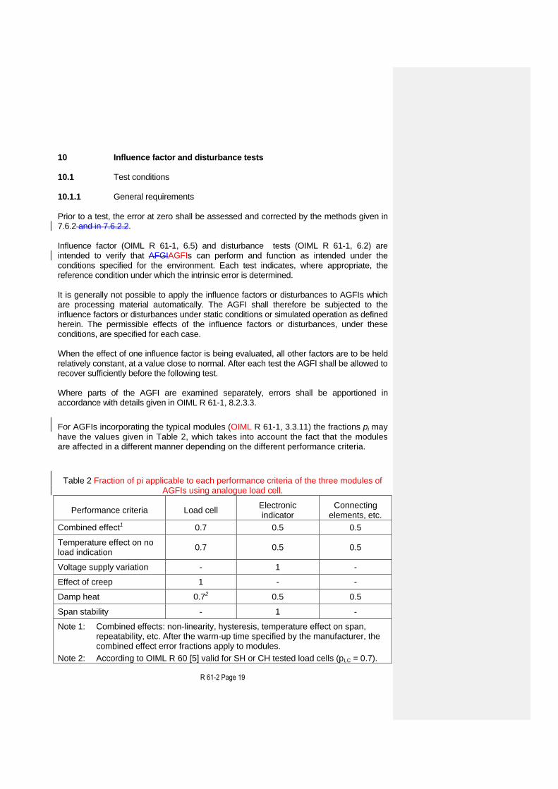
For AGFIs incorporating the typical modules (OIML R 61-1, 3.3.11) the fractions pi may have the values given in Table 2, which takes into account the fact that the modules are affected in a different manner depending on the different performance criteria.
Table 2 Fraction of pi applicable to each performance criteria of the three modules of AGFIs using analogue load cell.
Note 1: Combined effects: non-linearity, hysteresis, temperature effect on span, repeatability, etc. After the warm-up time specified by the manufacturer, the combined effect error fractions apply to modules.
Note 2: According to OIML R 60 [5] valid for SH or CH tested load cells (pLC = 0.7).
R 61-2 Page 20
Note 3: The sign “–” means “not applicable”.
The operational status of the AGFI or simulator shall be recorded for each test. When the AGFI is connected in other than a normal configuration, the procedure shall be mutually agreed on by the approving authority and the applicant. 10.1.2 Simulated set-upSimulator requirements 10.1.2.1 General The simulated set-upsimulator for influence factor and disturbance tests should include all electronic devices of the weighing system. 10.1.2.2 Load cell A number of tests can be performed with either a load cell or a simulator but both have to fulfill the requirements in the following paragraph. However the disturbance tests should be performed with a load cell or a weighing platform with load cell being the most realistic case. If a simulator is used to test a module, the repeatability and stability of the simulator should make it possible to determine the performance of the module with at least the same accuracy as when a complete AGFI is tested with weights, the mpe to be considered being those applicable to the module. If a simulator is used, this shall be noted in the report format for type evaluation OIML R 61-3. 10.1.2.3 Interfaces (details as given in OIML R 61-1, 6.9) Susceptibility or improvements that would result from the use of electronic interfaces or peripheral equipment shall be simulated in the tests. 10.1.2.4 Documentation Simulators shall be defined in terms of hardware and functionality by reference to the AGFI under test, and by any other documentation necessary to ensure reproducible test conditions. This information shall be attached to, or be traceable from the test report.
R 61-2 Page 21
10.2 Influence factor tests
Summary of influence factor tests
§ Test Characteristic under test
Conditions applied
10.2.1 Warm-up time Influence factor mpe
10.2.2 Temperature with static load Influence factor mpe
10.2.3 Temperature effect on no-load indication (dry heat and cold)
Influence factor mpe
10.2.4 Damp heat test, steady state Influence factor mpe
10.2.5 AC mains voltage variation Influence factor mpe
10.2.6 DC mains voltage variation Influence factor mpe
10.2.7 Low voltage of internal battery (not connected to the mains power)
Influence factor mpe
10.2.8 Power from external 12 V and 24 V road vehicle batteries
Influence factor mpe
10.2.9 Tilting Influence factor mpe
Note: Although IEC Standards are mentioned, the requirements of OIML R 61 have to be fulfilled. Differences should be taken into account.
R 61-2 Page 22
10.2.1 Warm-up time (OIML R 61-1, 6.8) This test is to verify that metrological performance is maintained in the period immediately after switch-on. The method is to check that automatic operation is inhibited until a stable indication is obtained and to verify that the zero variation and the errors at Max comply with the specified requirements during the first 30 minutes of operation. If the zero is set as part of the normal automatic weighing cycle then this function shall be enabled or simulated as part of the test. Other test methods which verify that metrological performance is maintained during the first 30 minutes of operation may be used. a) Disconnect the AGFI from the power supply for a period of at least 8 hours prior to
the test. b) Reconnect the AGFI and switch on while observing the load indicator. c) Check that it is not possible to initiate automatic weighing until the indicator has
stabilized. d) As soon as the indication has stabilized, set the AGFI to zero if this is not done
automatically. e) Determine the error at zero by the method of 7.6.2.1, and specify this error as E0I
(error of initial zero-setting) at first and as E0 (zero-setting error) when repeating this step.
f) From (e) verify that E0I is not greater than the mpe specified in OIML R 61-1, 5.8.2.
g) Apply a static load close to Max. Determine the error by the method of 7.6.2.1 and 7.6.2.2.
h) Repeat steps (e), (f) and (g) (every minute within the first 5 minutes, between 5 and 15 minutes every two minutes, after 15 minutes take the readings every five minutes. Observe whether the drift has stopped after 30 minutes. If not, continue taking the readings until warm-up process has completely finished and the indication both at zero and Max remain stable (show no further drift).
i) From (g) and (h) verify that: 1) The error (corrected for zero error) for a static load close to Max is not greater
than the mpe specified in OIML R 61-1, 5.8.2, 2) After each time interval the zero-variation error (E0 - E0I) is not greater than the
mpe specified in OIML R 61-1, 5.8.2.
R 61-2 Page 23
10.2.2 Temperature test with static load (OIML R 61-1, 4.8.2.1) (See Figure 1 below as a practical approach to performing the temperature tests)
Test method Gradual exposure to high and low temperatures not allowing condensation to occur
Applicability General
Object of the test Verification of compliance with the provisions in OIML R 61-1, 4.3.2 under conditions of high and low temperature specified in OIML R 61-1, 4.8.2.1
Precondition The electrical power of the EUT is switched on for at least a 16 hours time period while taking into account the warm-up time specified by the manufacturer.
Condition of the EUT
The electrical power supplied to the EUT shall not be switched off and the EUT shall not be readjusted at any time during the test. This test may be combined with test on temperature effect on no-load indication. In such case the automatic zero-setting or zero-tracking, where available, shall not be enabled. When this test is not combined with the test on temperature effect on no-load indication the automatic zero-setting or zero-tracking, where available, shall be enabled as for normal operation
Test procedure in brief
The test comprises exposure to the specified high temperature under “free air” conditions during the period of at least 2 hours (the period specified is the period following the moment at which the EUT has reached temperature stability). “Free air” conditions meaning sufficient air circulation to keep the temperature at a stable level. The change in temperature shall not exceed 1 °C/min during heating up and cooling down. The stabilizing time at each temperature is at least 2 hours. The absolute humidity of the test atmosphere shall not exceed 20 g/m3. When tests are performed at temperatures below 35 °C, the relative humidity shall not exceed 50 %. Temperature sequence: 1) Reference temperature of 20 °C 2) Specified high temperature 3) Specified low temperature 4) Temperature of 5 °C if the specified low temperature is
0 °C, and 5) Reference temperature of 20 °C
Notes Adjust the EUT as close to zero indication as practicable to ensure that the test result is unaffected by the automatic zero-
R 61-2 Page 24
setting function which should therefore be disabled.
EUT performance
After stabilization at the relevant temperature and again at each specified temperature conduct the following: The EUT shall be tested with at least five different static test loads (or simulated loads) including Max and Min capacities. When loading or unloading weights the load has to be respectively increased or decreased monotonically record the following data: a) date and time, b) temperature, c) relative humidity, d) test load value, e) indicated values, f) error values, g) functional performance
Permitted maximum deviation
All functions shall operate as designed. All errors shall be within the maximum permissible errors specified in OIML R 61-1, 4.3.2
10.2.3 Temperature effect on no-load indication (dry heat and cold) (OIML R 61-1, 4.8.2.3)
Table 3b Temperature test at no load condition (dry heat and cold)
Test method Gradual exposure to high and low temperatures not allowing condensation to occur
Applicability
General applicable. This test should not be performed for AFGIAGFIs that have automatic zero - setting as part of every automatic weighing cycle. This test may be combined with the general temperature test specified above.
Object of the test Verification of compliance with the provisions in OIML R 61-1, 4.3.2 under conditions of high and low temperature specified in OIML R 61-1, 4.8.2.3
Precondition The electrical power of the EUT is switched on for at least a 16 hours time period while taking into account the warm-up time specified by the manufacturer.
Condition of the EUT
The electrical power supplied to the EUT shall not be switched off and the EUT shall not be readjusted at any time during the test. The automatic zero-setting or zero-tracking, where available, shall not be enabled.
Test procedure in brief
The AFGIAGFI is set to zero, the temperature is then changed to the prescribed highest and lowest temperatures as well as at 5 °C. After stabilization, the error of the zero indication is determined. The change in zero indication per 5 °C is calculated. The changes of these errors per 5 °C are calculated for any two consecutive temperatures of this test. Temperature sequence:
R 61-2 Page 25
1) Reference temperature of 20 °C 2) Specified high temperature 3) Specified low temperature 4) Temperature of 5 °C if the specified low temperature is
0 °C, and 5) Reference temperature of 20 °C
After the first time setting at reference temperature and stabilization the EUT is set to zero.
Note Performing a test for verification of the clause 4.8.2.3 is not required in case of automatic zero-setting as part of every weighing cycle.
EUT performance
Determine the error at zero, each time just before changing to a next temperature level. After stabilization at each specified temperature conduct the following: - determine the error at zero indication and - calculate the change in zero indication per 5 °C. These zero error gradients (per 5 °C) shall be calculated for any two consecutive temperatures of this test. At each temperature record the following data: a) date and time, b) temperature, c) relative humidity, d) zero error, e) calculated zero error gradient
Permitted maximum deviation
All functions shall operate as designed. The change in zero indication shall over a temperature difference of 5 °C not vary by more than the maximum permissible error specified in OIML R 61-1, 4.3.2 for the Minfill of the AGFI.
R 61-2 Page 26
Formatted: Font: Arial, 11 pt,Condensed by 0.15 pt
R 61-2 Page 27
10.2.4 Damp heat test 10.2.4.1 Damp heat, steady state test (non-condensing) (OIML R 61-1, 4.8.1, 6.5) The tests in 10.2.4.1 or 10.2.4.2 may be performed alternatively in accordance with R 61-1, 4.8.1, the option chosen being mentioned in the type approval certificate.Damp heat, steady state test in Table 4 is performed in accordance with OIML R 61-1, 4.8.1.
Table 4a Damp heat, steady-state (non condensing)
Applicable standards
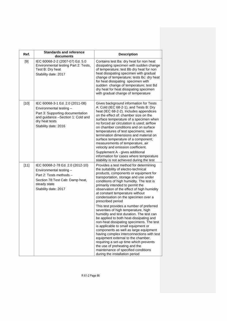
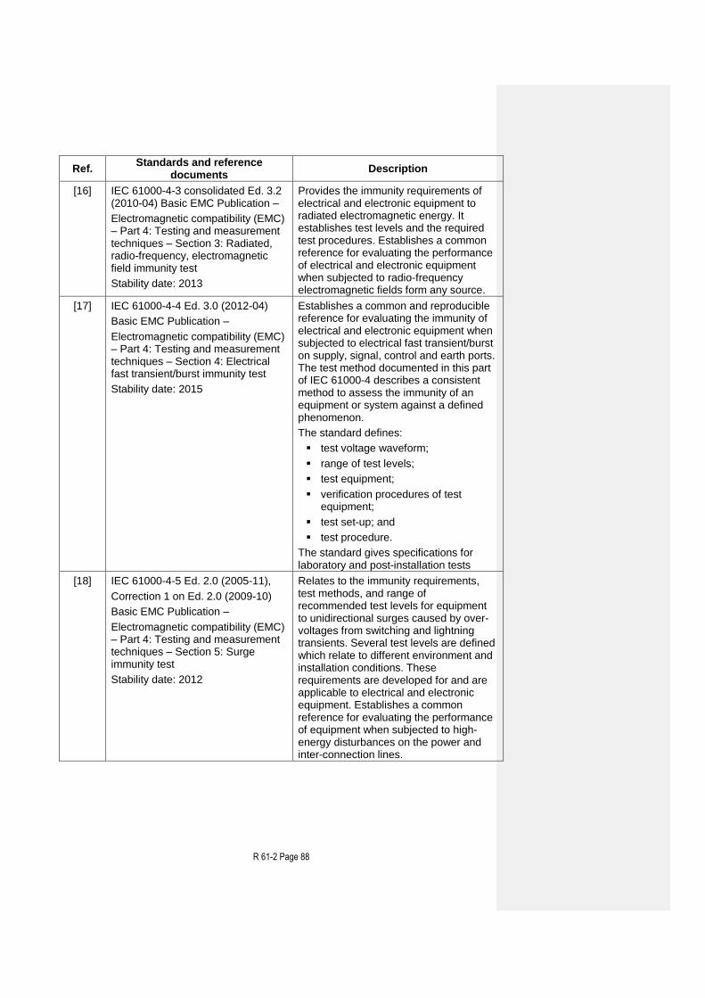
IEC 60068-2-78 [11], IEC 60068-3-4 [12]
Test method Exposure to damp heat in steady-state
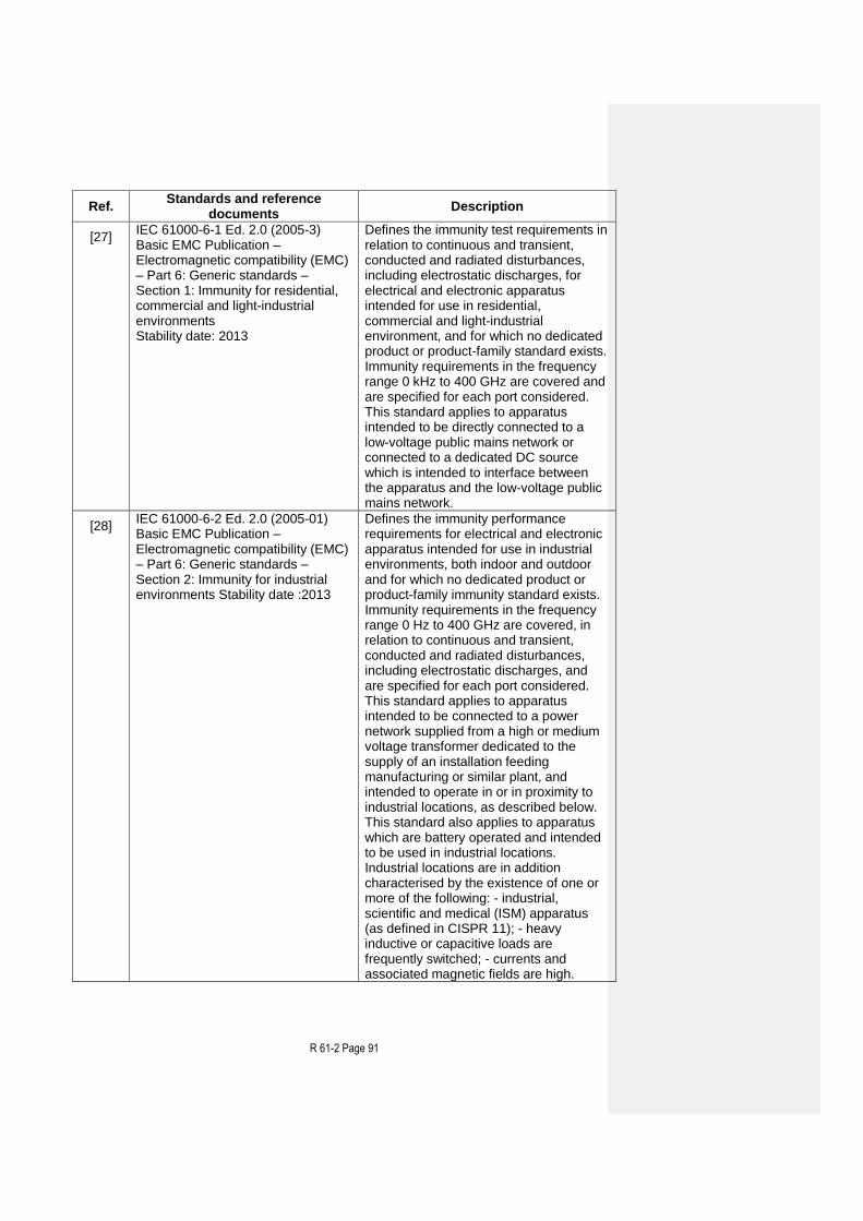
Applicability This test is considered general applicable where the AFGIAGFI is expected to be used in a non-controlled climatic environment, where adsorption or absorption play the main part.
Object of the test Verification of compliance with the provisions in R 61-1, 4.3.2 under conditions of high humidity and constant temperature specified in OIML R 61-1, 4.8.1.
Precondition The electrical power of the EUT is switched on for at the warm-up time specified by the manufacturer.
Condition of the EUT
The electrical power supplied to the EUT shall not be switched off and the EUT shall not be readjusted at any time during the test. The automatic zero-setting or zero-tracking, where available, shall be enabled as for normal operation.
Test procedure in brief
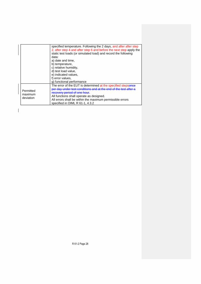
A complete weighing test in accordance with 8.2 and 9.3. The EUT shall be tested with at least five different static test loads (or simulated loads) including Max and Min capacities. The test comprises exposure to the specified high level temperature and the specified constant relative humidity for a certain fixed period of time as defined by the test level chosen. The EUT shall be handled such that no condensation of water occurs on it. Climate test sequence: 1. Set at reference temperature of 20 °C and at 50 % relative humidity, 2. Maintain for 3 hours at reference temperature of 20 °C and 50 % relative humidity, 3. Set at specified high temperature at 85 % relative humidity, 4. After reaching high temperature at 85 % relative humidity maintain during 48 hours this high temperature and humidityMaintain during 48 hours this high temperature and 85 % relative humidity, 5. Set at reference temperature of 20 °C and at 50 % relative humidity, 6. Maintain for 3 hours at reference temperature at 50 % relative humidity.
Relative humidity (RH) Duration
Test level 85 48
unitUnit % hours
EUT performance After stabilization at the relevant temperature and again at each
R 61-2 Page 28
specified temperature. Following the 2 days, and after after step 2, after step 4 and after step 6 and before the next step apply the static test loads (or simulated load) and record the following data: a) date and time, b) temperature, c) relative humidity, d) test load value, e) indicated values, f) error values, g) functional performance
Permitted maximum deviation
The error of the EUT is determined at the specified stepsonce per day under test conditions and at the end of the test after a recovery period of one hour. All functions shall operate as designed. All errors shall be within the maximum permissible errors specified in OIML R 61-1, 4.3.2
R 61-2 Page 29
10.2.4.2 Damp heat, cyclic test (condensing) Damp heat, cyclic tests in Table 4b is performed in accordance with OIML R 61-1, 4.8.1.
Table 4b Damp heat, cyclic (condensing)
Applicable standards
IEC 60068-2-30 [23], IEC 60068-3-4 [12]
Test method Exposure to damp heat with cyclic temperature variation
Applicability Applicable where condensation is concerned and/or when the penetration of vapour is expected which especially applies to outdoor used AGFIs.
Object of the test Verification of compliance with the provisions in R 61-1 4.3.2 under conditions of high humidity combined with cyclic temperature changes specified in R 61-1, 4.8.1.
Precondition The electrical power of the EUT is switched on for at least the warm-up time specified by the manufacturer.
Condition of the EUT
The electrical power supplied to the EUT shall not be switched off and the EUT shall not be readjusted at any time during the test. The automatic zero-setting or zero-tracking, where available, shall be enabled as for normal operation.
Test procedure in brief
A complete weighing test in accordance with 8.2 and 9.3. The EUT shall be tested with at least five different static test loads (or simulated loads) including Max and Min capacities. The test comprises exposure to cyclic temperature variation between 25 °C and the appropriate upper temperature while maintaining the relative humidity above 95 % during the temperature change and the low temperature phases and at or above 93 % RH at the upper temperature phases. Condensation is expected to occur on the EUT during the temperature rise. The 24 h cycle comprises: 1) temperature rise during 3 hours, 2) temperature maintained at upper value until 12 hours from the start of the cycle, 3) temperature lowered to lower temperature level within a period of 3 to
6 hours, the declination (rate of fall) during the first hour and a half being such that the lower temperature level would be reached in a 3 hour period,
4) temperature maintained at the lower level until the 24 h period is completed. The stabilizing period before and recovery period after the cyclic exposure shall be such that the temperature of all parts of the EUT is within 3 °C of its final value. Special electrical conditions and recovery conditions may need to be specified. The stabilizing period before and recovery after the cyclic exposure shall be such that all parts of the EUT are approximately at their final temperature.
Test level Unit
Upper temperature 40 °C
Duration 2 24-hour cycle(s)
R 61-2 Page 30
EUT performance
After the exposure to damp heat, at no load and subsequently at test load condition record the following data: a) date and time, b) temperature, c) relative humidity, d) test load value, e) indicated values, f) error values, g) functional performance
Permitted maximum deviation
The error of the EUT is determined once per day under test conditions and at the end of the test after a recovery period of one hour. All functions shall operate as designed. All errors shall be within the maximum permissible errors specified in 4.3.2
R 61-2 Page 31
10.2.5 AC mains voltage variation (OIML R 61-1, 4.8.3)
Table 5 AC mains voltage variation
Applicable standards
IEC/TR3 61000-2-1 [13], IEC 61000-4-1 [14]
Test method Applying low and high level AC mains power voltage (single phase)
Applicability
Applicable for AFGIAGFIs which are temporarily or permanently connected to an AC mains power network while in operation. This test is not applicable to equipment powered by a road vehicle battery.
Object of the test Verification of compliance with the provisions in OIML R 61-1, 4.3.2 under conditions of AC mains network voltage changes between upper and lower limit specified in OIML R 61-1, 4.8.31)
Precondition The electrical power of the EUT is switched on for at least the warm-up time specified by the manufacturer.
Condition of the EUT
The electrical power supplied to the EUT shall not be switched off and the EUT shall not be readjusted at any time during the test. The automatic zero-setting or zero-tracking, where available, shall be enabled as for normal operation.
Test procedure in brief
The test comprises exposure of the EUT to the lower and upper limit power supply condition for a period sufficient for achieving temperature stability and subsequently performing the required measurements. Test Sequence: 1. Reference voltage level, 2. Upper voltage level, 3. Lower voltage level, 4. Reference voltage level, In the case of three phase power supply, the voltage variation shall apply for each phase successively.
EUT performance
The EUT shall be applied and tested with a test load approximately equal to the minimum capacity and on load between ½ Max and Max. After stabilization at the relevant voltage record the following: a) date and time, b) reference Voltage level 2) c) temperature, d) relative humidity, e) test load value, f) indicated values, g) error values, h) functional performance
Test level Upper limit Unom1 + 10 % 1)
Lower limit Unom2 15 % 1)
Notes
1) The values of Unom are those as marked on the AFGI. If a range is specified Unom1 concerns the highest and Unom2 concerns the lowest value. If only one nominal mains voltage value (Unom) is specified then Unom1 = Unom2 = Unom. For three phase mains power supplies, the voltage variation is applicable for each of the phases successively.
R 61-2 Page 32
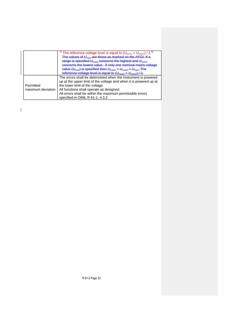
2) The reference voltage level is equal to (Unom1 + Unom2) / 2.1) The values of Unom are those as marked on the AFGI. If a range is specified Unom1 concerns the highest and Unom2 concerns the lowest value. If only one nominal mains voltage value (Unom) is specified then Unom1 = Unom2 = Unom. The reference voltage level is equal to (Unom1 + Unom2) / 2.
Permitted maximum deviation
The errors shall be determined when the instrument is powered up at the upper limit of the voltage and when it is powered up at the lower limit of the voltage. All functions shall operate as designed. All errors shall be within the maximum permissible errors specified in OIML R 61-1, 4.3.2
R 61-2 Page 33
10.2.6 DC mains voltage variation (OIML R 61-1, 4.8.3)
Table 6 DC mains voltage variation
Applicable standard
IEC 60654-2 [32]
Test method Applying low and high level DC mains power voltage
Applicability
Applicable for AFGIAGFIs which are temporarily or permanently connected to a DC mains power network while in operation and generally only applicable in industrial environment. This test is not applicable to equipment powered by a road vehicle battery.
Object of the test
Verification of compliance with the provisions in OIML R 61-1, 4.3.2 under conditions of DC mains power voltage changes between upper and lower limit specified in OIML R 61-1, 4.8.3 1)
Precondition The electrical power of the EUT is switched on for at least the warm-up time specified by the manufacturer.
Condition of the EUT
The electrical power supplied to the EUT shall not be switched off and the EUT shall not be readjusted at any time during the test. The automatic zero-setting or zero-tracking, where available, shall be enabled as for normal operation.
Test procedure in brief
The test comprises exposure to the specified power supply condition for a period sufficient for achieving temperature stability and subsequently performing the required measurements. Test Sequence:
a) date and time, b) reference voltage level 2) c) temperature, d) relative humidity, e) test load value, f) indicated values, g) error values, h) functional performance
Test level
The upper voltage limit is the DC level at which the EUT has been designed to automatically detect high-level conditions. The lower limit will be the DC level at which the EUT has been designed to automatically detect low-level conditions.
Notes
1) The DC operating range is the range as specified by the manufacturer but not less than Unom – 15 % ≤ Unom ≤ Unom + 10 %. 2)The reference voltage level is the nominal DC voltage (Unom) specified by the manufacturer,
EUT performance
The EUT shall be applied and tested with a test load approximately equal to the minimum capacity and on load between ½ Max and Max. After stabilization at the relevant voltage record the following: a) date and time, b) temperature, c) relative humidity, d) test load value, e) indicated values,
R 61-2 Page 34
f) error values, g) functional performance
Permitted maximum deviation
The errors shall be determined when the supplied voltage to the EUT at the upper limit level and when it is at the lower limit level. All functions shall operate as designed. All errors shall be within the maximum permissible errors specified in OIML R 61-1, 4.3.2
R 61-2 Page 35
10.2.7 Low voltage of internal battery (not connected to the mains power) (OIML R 61-1, 4.8.3)
Table 7 Low voltage of internal battery (not connected to the mains power)
Applicable standards
No standard is available
Test method Applying minimum supply voltage
Applicability Applicable to all AFGIAGFIs supplied by internal battery
Object of the test Verification of compliance with the provisions in OIML R 61-1, 4.3.2 during low battery voltage specified in OIML R 61-1, 4.8.3
Precondition
The electrical power of the EUT is switched on for at least the warm-up time specified by the manufacturer. The electrical power supplied to the EUT shall not be switched off and the EUT shall not be readjusted at any time during the test. The automatic zero-setting or zero-tracking, where available, shall be enabled as for normal operation.
Test procedure in brief
The test comprises exposure of the EUT to the specific low battery level condition during a period sufficient for achieving temperature stability and for performing the required measurements. The maximum internal impedance of the battery and the minimum battery supply voltage level (Ubmin) shall be specified by the manufacturer of the AFGIAGFI. In case of simulating the battery, by using an alternative power supply, the internal impedance of the specified type of battery shall also to be simulated. The alternative power supply shall be capable of delivering sufficient current at the applicable supply voltage. The test sequence is as follows: a) Let the power supply stabilize at a voltage as defined
within the rated operating conditions and apply the test loadLet the power supply stabilize at a voltage as defined within the rated operating conditions and apply the measurement and/or loading condition.
b) Record:
the data defining the actual measurement conditions including date, time and environmental conditions,
the actual power supply voltage. c) Perform measurements and record the error (-s) and other
relevant performance parameters. d) Verify compliance with OIML R 61-1, 4.3.2 e) Repeat the above procedure with actual supply voltage at
Ubmin and again at 0,9 Ubmin Verify compliance with OIML R 61-1, 4.3.2.
Lower limit of the voltage
The lowest voltage at which the EUT functions properly according to the specifications
Number of test cycles
At least one test cycle for each functional mode
EUT performance
The EUT shall be applied and tested with a test load approximately equal to the minimum capacity and on load between ½ Max and Max. After stabilization at the relevant voltage record the following: a) date and time,
R 61-2 Page 36
b) temperature, c) relative humidity, d) test load value, e) indicated values, f) error values, g) functional performance
Permitted maximum deviation
All errors shall be within the maximum permissible errors specified in OIML R 61-1, 4.3.2. For voltages at and above Ubmin, all functions shall operate as designed; for voltages below Ubmin, the AFGIAGFI may automatically resume normal operation. During all phases of the test the loss of any previous measurement data is not acceptable.
R 61-2 Page 37
10.2.8 Power from external 12 V and 24 V road vehicle batteries (OIML R 61-1, 4.8.3)
Table 8 Voltage variations
Applicable standard
ISO 16750-2 [24]
Test method Variation in supply voltage
Applicability Applicable to all AFGIAGFIs supplied by the internal battery of a vehicle and charged by use of a combustion engine driven generator.
Object of the test Verification of compliance with the provisions in OIML R 61-1, 4.3.2 under conditions of high while charging) and low battery voltage specified in OIML R 61-1, 4.8.3.
Precondition The electrical power of the EUT is switched on for at least the warm-up time specified by the manufacturer.
Condition of the EUT
The electrical power supplied to the EUT shall not be switched off and the EUT shall not be readjusted at any time during the test. The automatic zero-setting or zero-tracking, where available, shall be enabled as for normal operation.
Test procedure in brief
The test comprises exposure to the specified maximum and minimum power supply voltage conditions for a period sufficient for achieving temperature stability and performing the required measurements at these conditions.
Nominal battery voltage
Unom = 12 Unom = 24 V
Lower limit
Upper limit
Lower limit
Upper limit
Test level 9 16 16 32 V
EUT performance
The EUT shall be applied and tested with a test load approximately equal to the minimum capacity and on load between ½ Max and Max. After stabilization at the relevant voltage record the following: a) date and time, b) temperature, c) relative humidity, d) test load value, e) indicated values, f) error values, g) functional performance
Permitted maximum deviation
All functions shall operate as designed. All errors shall be within the maximum permissible errors specified in OIML R 61-1, 4.3.2.
R 61-2 Page 38
10.2.9 Tilting (OIML R 61-1, 4.8.4) No reference to international standards can be given at the present time. This test should therefore be conducted as described below. Note: This test only applies to AFGIAGFIs that will not be permanently installed. This
test is not required for transportable AFGIAGFIs with a leveling device and a level indicator if it can be established that the tilt can be adjusted to 1 % or less.
If R 61-1, 4.8.4 b) applies, the mentioned requirements must shall be tested in addition. 10.2.9.1 Tilting of AGFIs fitted with a levelling device and a level indicator, or a tilt
sensor (OIML R 61-1, 4.8.4 a and 4.8.4 b) 10.2.9.1.1 Tilting at no-load The AGFI shall be set to zero in its reference position (not tilted). The AGFI shall then be tilted longitudinally up to the limiting value of tilting. The zero indication is noted. This test shall be repeated for each direction (longitudinally backwards and forwards, transversally leftside and rightside). 10.2.9.1.2 Tilting when loaded The AGFI shall be set to zero in its reference position and two weighings shall be carried out at a load close to the lowest load where the maximum permissible error changes, and at a load close to Max. The AGFIs is then unloaded and tilted longitudinally and set to zero. The tilting shall be equal to the limiting value of tilting. Weighing tests as described above shall be performed. This test shall be repeated for each direction (longitudinally backwards and forwards, transversally leftside and rightside). 10.2.9.2 AGFIs not fitted with a levelling device and a level indicator, or an
automatic tilt sensor (OIML R 61-1, 4.8.4 c and d) The test in 10.2.9.2 only applies for AGFIs liable to be tilted and not fitted with a level levelling device or indicator which clearly indicates when the maximum permissible tilt has been exceeded nor with an automatic tilt sensor which clearly indicates when the maximum permissible tilt has been exceeded (e.g. by producing an error code or signal) and inhibits any printout and transmission of measurement data.
Table 9 – Tilt test
Object of the test: To verify compliance with the provisions given in OIML R 61-1, 4.8.4.
Test procedure in brief: The test consist of tilting the EUT both forwards and backwards, longitudinally and from side to side (transversely), while observing the weight indications for a static test load.
Test severity: Two test loads at a tilt of 5 % at Min (load close to the lowest load where the maximum permissible
R 61-2 Page 39
error changes) and Max. In case of AGFIs intended for installation in vehicles the test shall be conducted at a tilt of 10 % close to the maximum tilt.
Condition of EUT: The EUT is switched on for at least the warm-up time specified by the manufacturer. During the test the electrical power supplied to the EUT shall not be switched off.
Adjust the EUT in its reference position (not tilted) as close to zero indication as practicable. If the AFGIAGFI is provided with automatic zero-setting it shall not be in operation.
Test sequence: Record the zero indication. Apply the test load and record the indication. Remove the test load.
Tilt the EUT longitudinally to the appropriate extent and record the zero indication. Apply the test load approximately equal to the Max and record the indication. Remove the test load.
Without further adjustment to any control affecting metrological performance tilt the EUT to the appropriate extent in the opposite direction and repeat the weighing tests as above.
Tilt the EUT in the transverse direction to the appropriate extent and repeat the above tests.
Tilt the EUT in the opposite direction and repeat the above tests.
Record the following data for each of the test set-ups as prescribed above: a) Date and time b) Test load c) Indications at each tilt d) Errors e) Functional performance
In order to determine the influence of tilting on the loaded AFGIAGFI, the indication obtained at each tilt shall be corrected for the deviation from zero which the AFGIAGFI had prior to loading.
Maximum allowable variations: All indications shall be within maximum permissible errors specified in OIML R 61-1, 4.3.2.
R 61-2 Page 40
10.3 Disturbance tests (OIML R 61-1, 6.2)
Summary of disturbance tests
§ Test Condition applied
10.3.1 Damp heat, cyclic Significant fault
10.3.210.3.1
AC mains voltage dips, short interruptions and reductions
Significant fault
10.3.310.3.2
Bursts (fast transient tests) on mains power lines and on signal, data and control lines
Significant fault
10.3.410.3.3
Electrostatic discharge Significant fault
10.3.510.3.4
Immunity to electromagnetic fields Significant fault
10.3.610.3.5
Surges on AC and DC mains power lines and on signal, data and control lines
Significant fault
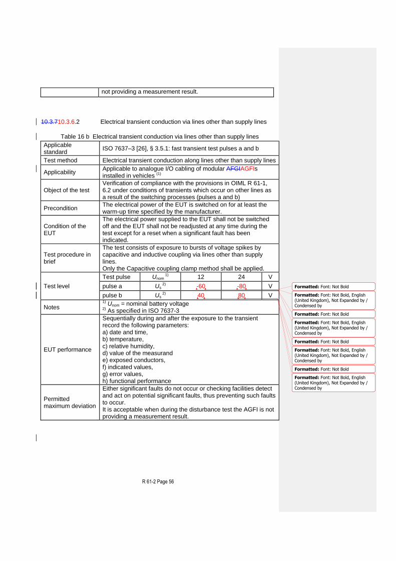
10.3.10.3.6 Electrical transient conduction for instruments powered by 12V and 24V batteries
Significant fault
10.3.10.3.7 Ripple on DC mains power Significant fault
10.3.8 Battery voltage variations during starting up a vehicle engine
Significant fault
10.3.1010.3.9
Load dump test Significant fault
10.3.1110.3.10
DC mains voltage dips, short interruptions and (short term) variations
Significant fault
Note 1: Tests shall be conducted to the appropriate classification for electrical tests. The severity level stated in the tests 10.3.1 to 10.3.1110.3.10 apply to AGFIs installed and used in locations with significant or high levels of electromagnetic disturbances corresponding to those likely to be found in industrial environments, class E2 of OIML D11 [3].
Note 2: If there are interfaces on the instrument (or simulator), the use of these interfaces to other equipment shall be simulated in the tests. For this purpose, either an appropriate peripheral device or 3 m of interface cable to simulate the interface impedance of the other equipment shall be connected to each different type of interface.
10.3.1 Damp heat, cyclic test (condensing) Damp heat, cyclic testsinTable 10 is performed in accordance with OIML R 61-1, 4.8.1.
Table 10 Damp heat, cyclic (condensing)
Applicable standards
IEC 60068-2-30 [23], IEC 60068-3-4 [12]
Test method Exposure to damp heat with cyclic temperature variation
Applicability Applicable where condensation is concerned and/or when the penetration of vapour is expected which especially applies to outdoor used s.
Object of the test Verification of compliance with the provisions in 4..2 under conditions of
Formatted: Hyphenate
Formatted: Left
R 61-2 Page 41
high humidity combined with cyclic temperature changes specified in .
Precondition The electrical power of the EUT is switched on for at least the warm-up time specified by the manufacturer.
Condition of the EUT
The electrical power supplied to the EUT shall not be switched off and the EUT shall not be readjusted at any time during the test. The automatic zero-setting or zero-tracking, where available, shall be enabled as for normal operation.
Test procedure in brief
The test comprises exposure to cyclic temperature variation between 25 °C and the appropriate upper temperature while maintaining the relative humidity above 95 % during the temperature change and the low temperature phases and at or above 93 % RH at the upper temperature phases. Condensation is expected to occur on the EUT during the temperature rise. The 24 h cycle comprises: 1) temperature rise during 3 hours, 2) temperature maintained at upper value until 12 hours from the start of the cycle, 3) temperature lowered to lower temperature level within a period of 3 to 6 hours, the declination (rate of fall) during the first hour and a half being such that the lower temperature level would be reached in a 3 hour period, 4) temperature maintained at the lower level until the 24 h period is completed. The stabilizing period before and recovery period after the cyclic exposure shall be such that the temperature of all parts of the EUT is within 3 °C of its final value. Special electrical conditions and recovery conditions may need to be specified. The stabilizing period before and recovery after the cyclic exposure shall be such that all parts of the EUT are approximately at their final temperature.
Test level Unit
Upper temperature 40
°C
Duration 2 24-hour cycle(s)
EUT performance
After the exposure to damp heat, at no load and subsequently at test load condition record the following data: a) date and time, b) temperature, c) relative humidity, d) test load value, e) indicated values, f) error values, g) functional performance
Permitted maximum deviation
The error of the EUT is determined once per day under test conditions and at the end of the test after a recovery period of one hour. All functions shall operate as designed. All errors shall be within the maximum permissible errors specified in 4..2
Formatted: Tab stops: Not at 0.56cm
Formatted: Indent: Left: 0 cm, Firstline: 0 cm, Tab stops: Not at 0.56 cm
Formatted: Tab stops: Not at 0.56cm
Formatted: Left
Formatted: Left
Formatted: Left
R 61-2 Page 42
10.3.210.3.1 AC mains voltage dips, short interruptions and reductions AC mains voltage dips and short interruptions tests are carried out according to Table 11.
Table 11 AC mains voltage dips, short interruptions and reductions
Test method Introducing short-time reductions of mains voltage using the test set-up defined in the applicable standard
Applicability
Applicable for AFGIAGFIs with rated input current of less than 16 A per phase which are temporarily or permanently connected to an AC mains power network while in operation. This test is only applicable to equipment powered by AC mains supply and is not applicable to equipment powered by a road vehicle battery.
Object of the test Verification of compliance with the provisions in OIML R 61-1, 6.2 under conditions of short time mains voltage reductions.
Precondition The electrical power of the EUT is switched on for at least the warm-up time specified by the manufacturer.
Condition of the EUT
The electrical power supplied to the EUT shall not be switched off and the EUT shall not be readjusted at any time during the test except for a reset when a significant fault has been indicated.
Test procedure in brief
A test generator is to be used which is suitable to reduce the amplitude of the AC mains voltage for the required period of time. The performance of the test generator shall be verified before connecting the EUT. The mains voltage reduction tests shall be repeated 10 times with intervals of at least 10 s between the tests. The tests shall be applied continuously during the measurement time. The interruptions and reductions are repeated throughout the time necessary to perform the whole test; for this reason, more than ten interruptions and reductions may be necessary.
Reduction of nominal voltage (Unom) unit
Tests and levels
Test a Reduction to 0 V
Duration 0.5 cycles
Test b Reduction to 0 V
Duration 1 cycles
Test c Reduction to 40 % of Unom
Duration 10/12 cycles
Test d Reduction to 70 % of Unom
Duration 25/30 cycles
Test e Reduction to 80 % of Unom
Duration 250/300 cycles
Short interruptions Reduction to 0 V
Duration 250/300 cycles
R 61-2 Page 43
EUT performance
The EUT shall be applied and tested with a test load close to zero (10 d). The fault of the EUT is determined separately for each of the different dips and reductions. Sequentially during and after the exposure to the disturbance record the following parameters: a) date and time, b) temperature, c) relative humidity, d) value of the measurand e) percentage of voltage reduction and duration, f) indicated values, g) error values, h) functional performance
Permitted maximum deviation
Either significant faults do not occur or checking facilities detect and act on potential significant faults, thus preventing such faults to occur.
Formatted: Font: Italic
R 61-2 Page 44
10.3.310.3.2 Bursts (fast transient tests) on mains power lines and on signal,
data and control lines Electrical bursts tests (fast transient tests) are carried out according to Tables 12a and Table 12b.
Table 12a Bursts (transients) on AC and DC mains
Applicable standards
IEC 61000-4-4 [17]
Test method Introducing transients on the mains power lines
Applicability Applicable for AFGIAGFIs which are temporarily or permanently connected to a mains power network while in operation
Object of the test Verification of compliance with the provisions in OIML R 61-1, 6.2 during conditions where electrical bursts are superimposed on the mains voltage.
Precondition The electrical power of the EUT is switched on for at least the warm-up time specified by the manufacturer.
Condition of the EUT
The electrical power supplied to the EUT shall not be switched off and the EUT shall not be readjusted at any time during the test except for a reset when a significant fault has been indicated.
Test procedure in brief
A burst generator as defined in the referred standard shall be used. The characteristics of the generator shall be verified before connecting the EUT. The test comprises exposure to bursts of voltage spikes for which the output voltage on 50 Ω and 1000 Ω load are defined in the referred standard. Both positive and negative polarity of the bursts shall be applied. The duration of the test shall not be less than 1 minute for each amplitude and polarity. The injection network on the mains shall contain blocking filters to prevent the burst energy being dissipated in the mains. At least 10 positive and negative randomly phased bursts shall be applied. The bursts are applied during all the time necessary to perform the test; therefore, more bursts than indicated above may be necessary.
Amplitude (peak value) [kV] Repetition rate [kHz]
Test level 2 5
EUT performance
Sequentially during and after the exposure to the bursts record the following parameters: a) date and time, b) temperature, c) relative humidity, d) test load value, e) indicated values, f) error values, g) functional performance
Permitted maximum deviation
Either significant faults do not occur or checking facilities detect and act on potential significant faults, thus preventing such faults
R 61-2 Page 45
to occur. It is acceptable when during the disturbance test the AGFI is not providing a measurement result.
Table 12b Bursts (transients) on signal, data and control lines
Applicable standards
IEC 61000-4-4 [17]
Test method Introducing transients on signal, data and control lines
Applicability
Applicable for AFGIAGFIs containing active electronic circuits which during operation are permanently or temporarily connected to external electrical signal, data and/or control lines. Burst tests on signal lines are applicable only for I/O signal, data and control ports, with a cable length exceeding 3 m (as specified by the manufacturer).
Object of the test Verification of compliance with the provisions in OIML R 61-1, 6.2 during conditions where electrical bursts are superimposed on I/O and communication ports.
Precondition The electrical power of the EUT is switched on for at least the warm-up time specified by the manufacturer.
Condition of the EUT
The electrical power supplied to the EUT shall not be switched off and the EUT shall not be readjusted at any time during the test except for a reset when a significant fault has been indicated.
Test procedure in brief
A burst generator as defined in the referred standard shall be used The characteristics of the generator shall be verified before connecting the EUT. The test comprises exposure to bursts of voltage spikes for which the output voltage on 50 Ω and 1000 Ω load are defined in the referred standard. Both positive and negative polarity of the bursts shall be applied. The duration of the test shall not be less than 1 min for each amplitude and polarity. A capacitive coupling clamp as defined in the standard shall be used for the coupling of the bursts into the I/O and communication lines,
Test level unit
Amplitude (peak value)
1 kV
Repetition rate 5 kHz
EUT performance
Sequentially during and after the exposure to the bursts. Record the following parameters: a) date and time, b) temperature, c) relative humidity, d) value of the measurand e) exposed conductors, f) indicated values, g) error values, h) functional performance
Permitted maximum deviation
Either significant faults do not occur or checking facilities detect and act on potential significant faults, thus preventing such faults to occur.
R 61-2 Page 46
It is acceptable when during the disturbance test the AGFI is not providing a measurement result.
R 61-2 Page 47
10.3.410.3.3 Electrostatic discharge
Table 13 Electrostatic discharge
Applicable standard
IEC 61000-4-2 [15]
Test method Exposure to electrostatic discharge (ESD)
Applicability Applicable to all AFGIAGFIs
Object of the test Verification of compliance with the provisions in OIML R 61-1, 6.2 in case of direct exposure to electrostatic discharges or such discharges in the neighbourhood of the EUT.
Precondition The electrical power of the EUT is switched on for at least the warm-up time specified by the manufacturer.
Condition of the EUT
The electrical power supplied to the EUT shall not be switched off and the EUT shall not be readjusted at any time during the test. The automatic zero-setting or zero-tracking, where available, shall be enabled as for normal operation.
Test procedure in brief
The test comprises exposure of the EUT to electrical discharges. An ESD generator as defined in the referred standard shall be used and the test set-up shall comply with the dimensions, materials used and conditions as specified in the referred standard. Before starting the tests, the performance of the generator shall be verified. At least 10 discharges per preselected discharge location shall be applied. An EUT not equipped with a safety ground connection shall first be fully discharged before being exposed to a next discharge. The time interval between successive discharges shall be at least 1 second. Contact discharge is the preferred test method. Air discharge is far less defined and reproducible and therefore shall be used only where contact discharge cannot be applied. Direct application: In the contact discharge mode to be carried out on conductive surfaces, the electrode shall be in contact with the EUT before activation of the discharge. In such a case the discharge spark occurs in the vacuum relays of the contact discharge tip. On insulated surfaces only the air discharge mode can be applied. The EUT is approached by the charged electrode until a spark discharge occurs. Indirect application: The discharges are applied in the contact mode only on coupling planes mounted in the vicinity of the EUT. Conventionally 3 cycles of tests are performed starting each test at a different moment of the measuring cycle.
One of the following test levels may be specified:
Charge voltage unit
Test level Contact discharge 6 kV
Air discharge 8 kV
EUT performance Five measurements shall be performed at each surface exposed to the disturbance. Sequentially during and after the exposure to
Formatted: Font: Not Bold
Formatted: Font: Not Bold
Formatted: Font: Not Bold
R 61-2 Page 48
the discharges record the following parameters: a) date and time, b) temperature, c) relative humidity, d) test load e) value of the measurand, f) discharge type, level and side/surface exposed, g) indicated values, h) error values, i) functional performance
Permitted maximum deviation
Either significant faults do not occur or checking facilities detect and act on potential significant faults, thus preventing such faults to occur. It is acceptable when during the disturbance test the AGFI is not providing a measurement result. Make sure that transient changes of indication of more than the significant fault are detected, e.g. by setting the preset value of the fill to a value corresponding to the indication without disturbance plus the significant fault.
R 61-2 Page 49
10.3.510.3.4 Immunity to electromagnetic fields
10.3.510.3.4.1 Immunity to radiated (RF) electromagnetic fields Radiated, radio frequency electromagnetic immunity tests are carried out according to Table 14 b.
Table 14 b Immunity to radiated electromagnetic fields
Applicable standard
IEC 61000-4-3 [16]; IEC 61000-4-20 [21]
Test method Exposure to radiated radio frequency electromagnetic fields
Applicability Applicable for AGFIs containing active electronic circuits
Object of the test Verification of compliance with the provisions in OIML R 61-1, 6.2 while exposed to electromagnetic fields.
Precondition The electrical power of the EUT is switched on for at least the warm-up time specified by the manufacturer.
Condition of the EUT
The electrical power supplied to the EUT shall not be switched off and the EUT shall not be readjusted at any time during the test. The automatic zero-setting or zero-tracking, where available, shall be enabled as for normal operation.
Test procedure in brief
The EUT is exposed to electromagnetic fields with the required field strength and the field uniformity as defined in the referred standard. The level of field strength specified refers to the field generated by the unmodulated carrier wave. The EUT shall be exposed to the modulated wave field. The frequency sweep shall be made only pausing to adjust the RF signal level or to switch RF-generators, amplifiers and antennas if necessary. Where the frequency range is swept incrementally, the step size shall not exceed 1 % of the preceding frequency value. The dwell time of the amplitude modulated carrier at each frequency shall not be less than the time necessary for the EUT to be exercised and to respond, but shall in no case be less than 0.5 s. Adequate EM fields can be generated in facilities of different type and set-up the use of which is limited by the dimensions of the EUT and the frequency range of the facility.
Test level
Frequency range RF amplitude AM, sine wave
modulation
(26) 80 - 3000 10 80 1
MHz V/m % kHz
EUT performance
Sequentially during and after the exposure to the EM field record the following parameters: a) date and time, b) temperature, c) relative humidity, d) value of the measurand, e) field strength level, f) indicated values, g) error values,
R 61-2 Page 50
h) functional performance
Permitted maximum deviation
Either significant faults do not occur or checking facilities detect and act on potential significant faults, thus preventing such faults to occur. It is acceptable when during the disturbance test the AGFI is not providing a measurement result.
10.3.4.2 Immunity to conducted electromagnetic fields Conducted, radio frequency, electromagnetic field immunity tests are carried out according to Table 14 a.
Table 14 a Conducted (common mode) currents generated by RF EM fields
Applicable standard
IEC 61000-4-6 [19]
Test method Injection of RF currents representing exposure to RF electromagnetic fields
Applicability
Applicable for AFGIAGFIs containing active electronic circuits and equipped with ports for throughput or connection of external electrical wiring (mains power, signal, data and control lines)
Object of the test Verification of compliance with the provisions in OIML R 61-1, 6.2 while exposed to electromagnetic fields.
Precondition The electrical power of the EUT is switched on for at least the warm-up time specified by the manufacturer.
Condition of the EUT
The electrical power supplied to the EUT shall not be switched off and the EUT shall not be readjusted at any time during the test. The automatic zero-setting or zero-tracking, where available, shall be enabled as for normal operation.
Test procedure in brief
An RF EM current, simulating the influence of EM fields shall be coupled or injected into the power ports and I/O ports of the EUT using coupling/decoupling devices as defined in the referred standard. The characteristics of the test equipment consisting of an RF generator, (de-)coupling devices, attenuators, etc. shall be verified before connecting the EUT. If the EUT comprises several devices the tests shall be performed at each extremity of the cable if both of the elements are part of the EUT.
Frequency range RF amplitude AM, sine wave
modulation
Test level 0.15 – 80 10 80 1
Unit MHz V (e.m.f.) % kHz
Note
In the range from 26 MHz to 80 MHz, the type evaluation authority may decide to choose a transition frequency below 80 MHz. AboveBelow the selected transition frequency tests will be carried out according to Table 14a14 b. In the event of a
R 61-2 Page 51
dispute, the result of the test according to this Table 14a prevails.
EUT performance
Sequentially during and after the exposure to the RF current record the following parameters: a) date and time, b) temperature, c) relative humidity, d) value of the measurand, e) applied RF (e.m.f.) voltage level , f) indicated values, g) error values, h) functional performance
Permitted maximum deviation
Either significant faults do not occur or checking facilities detect and act on potential significant faults, thus preventing such faults to occur. It is acceptable when during the disturbance test the AGFI is not providing a measurement result.
R 61-2 Page 52
10.3.610.3.5 Surges on AC and DC mains power lines and on signal, data and
control control lines Electrical surge tests are carried out according to Table 15 a and Table 15 b.
Table 15 a Surges on AC and DC mains power lines
Applicable standard
IEC 61000-4-5 [18]
Test method Introducing electrical surges on the mains power lines
Applicability
Applicable for AFGIAGFIs which are temporarily or permanently connected to a mains power network while in operation This test is not applicable to AFGIAGFIs connected to a local power source through an indoor network
Object of the test Verification of compliance with the provisions in OIML R 61-1, 6.2 during conditions where electrical surges are superimposed on the mains voltage
Precondition The electrical power of the EUT is switched on for at least the warm-up time specified by the manufacturer.
Condition of the EUT
The electrical power supplied to the EUT shall not be switched off and the EUT shall not be readjusted at any time during the test except for a reset when a significant fault has been indicated.
Test procedure in brief
A surge generator as defined in the referred standard shall be used The characteristics of the generator shall be verified before connecting the EUT. The test comprises exposure to electrical surges for which the rise time, pulse width, peak values of the output voltage/current on high/low impedance load and the minimum time interval between two successive pulses are defined in the referred standard. At least 3 positive and 3 negative surges shall be applied. On AC mains supply lines the surges shall be synchronised with the AC supply frequency and shall be repeated such that injection of surges on all the 4 phase shifts: 0°, 90°, 180° and 270° compared to the mains phase is covered. The injection network circuit depends on the applicable conductor and is defined in the referred standard. The surges are applied during all the time necessary to perform the test; to that purpose more surges than indicated above may be necessary.
Mains mode AC DC
Line to line Line to ground
Line to line Line to ground
unit
Test level 1.0 2.0 1.0 2.0 kV
EUT performance
Sequentially during and after the exposure to the surges record the following parameters: a) date and time, b) temperature, c) relative humidity, d) test load value,
Either significant faults do not occur or checking facilities detect and act on potential significant faults, thus preventing such faults to occur. It is acceptable when during the disturbance test the AGFI is not providing a measurement result.
Table 15 b Surges on signal, data and control control lines
Applicable standard
IEC 61000-4-5 [18]
Test method Introducing electrical surges on signal, data and control control lines
Applicability
Applicable for AFGIAGFIs containing active electronic circuits which during operation are temporarily or permanently connected to electrical signal, data and/or control lines that may exceed a length of 10 m. This test is not applicable to AFGIAGFIs connected to a local power source through an indoor network.
Object of the test Verification of compliance with the provisions in OIML R 61-1, 6.2 during conditions where electrical surges are superimposed on I/O and communication ports.
Precondition The electrical power of the EUT is switched on for at least the warm-up time specified by the manufacturer.
Condition of the EUT
The electrical power supplied to the EUT shall not be switched off and the EUT shall not be readjusted at any time during the test except for a reset when a significant fault has been indicated.
Test procedure in brief
A surge generator as defined in the referred standard shall be used. The characteristics of the generator shall be verified before connecting the EUT. The test comprises exposure to electrical surges for which the rise time, pulse width, peak values of the output voltage/current on high/low impedance load and the minimum time interval between two successive pulses are defined in the referred standard. At least 3 positive and 3 negative surges shall be applied. The applicable injection network depends on the kind of wiring the surge is coupled into and is defined in the referred standard.
Unsymmetrical
lines Symmetrical
lines
Shielded I/O and
communication lines
Test Level
Line to line
Line(s) to ground
Line(s) to ground
Line(s) to ground
Unit
1.0 2.0 2.0 2.0 kV
EUT performance
Sequentially during and after the exposure to the surges record the following parameters: a) date and time, b) temperature, c) relative humidity,
Formatted: Font: Not Bold
Formatted: Font: Not Bold
Formatted: Font: Not Bold
Formatted: Font: Not Bold
R 61-2 Page 54
d) value of the measurand e) exposed conductors, f) indicated values, g) error values, h) functional performance
Permitted maximum deviation
Either significant faults do not occur or checking facilities detect and act on potential significant faults, thus preventing such faults to occur. It is acceptable when during the disturbance test the AGFI is not providing a measurement result.
R 61-2 Page 55
10.3.710.3.6 Electrical transient conduction for AFGIAGFIs powered by 12V and 24V
batteries 10.3.710.3.6.1 Electrical transient conduction along supply lines
Table 16 a Electrical transient conduction along supply lines
Applicable standard
ISO 7637–2 [25]
Test method Electrical transient conduction along supply lines.
Applicability Applicable to all AFGIAGFIs while in operation are supplied by the internal battery of a vehicle which may at the same time be charged by use of a combustion engine driven generator
Object of the test
Verification of compliance with the provisions in OIML R 61-1, 6.2 under the following conditions:
transients due to a sudden interruption of currents in a device connected in parallel with the device under test due to the inductance of the wiring harness (pulse 2a);
transients from DC motors acting as generators after the ignition is switched off (pulse 2b);
transients on the supply lines which occur as a result of the switching processes (pulses 3a and 3b).
Precondition The electrical power of the EUT is switched on for at least the warm-up time specified by the manufacturer.
Condition of the EUT
The electrical power supplied to the EUT shall not be switched off and the EUT shall not be readjusted at any time during the test except for a reset when a significant fault has been indicated.
Test procedure in brief
The test comprises exposure to disturbances on the power voltage by direct coupling into the supply lines.
Test pulse Unom1) 12 24 V
Test level
2a Us 2) + 50 + 50 V
2b Us 2) 10 20 V
3a Us 2) - 150 - 200 V
3b Us 2) + 100 + 200 V
Notes 1) Unom = nominal battery voltage 2) As specified in ISO 7637-2 [25]
EUT performance
Sequentially during and after the exposure to the transient record the following parameters: a) date and time, b) temperature, c) relative humidity, d) test load value, e) indicated values, f) error values, g) functional performance
Permitted maximum deviation
Either significant faults do not occur or checking facilities detect and act on potential significant faults, thus preventing such faults to occur. It is acceptable when during the disturbance test the AGFI is
Formatted: Indent: Left: 0 cm,Hanging: 2.54 cm
Formatted: Font: Not Bold, English(United Kingdom), Not Expanded by /Condensed by
Formatted: Font: Not Bold
Formatted: Font: Not Bold, English(United Kingdom), Not Expanded by /Condensed by
Formatted: Font: Not Bold
Formatted: Font: Not Bold, English(United Kingdom), Not Expanded by /Condensed by
Formatted: Font: Not Bold
Formatted: Font: Not Bold, English(United Kingdom), Not Expanded by /Condensed by
Formatted: Font: Not Bold
Formatted: Font: Not Bold, Italic
Formatted: Font: Not Bold
Formatted: Font: Not Bold
Formatted: Font: Not Bold, English(United Kingdom), Not Expanded by /Condensed by
Formatted: Font: Not Bold
Formatted: Font: Not Bold, English(United Kingdom), Not Expanded by /Condensed by
Formatted: Font: Not Bold, Italic
Formatted: Font: Not Bold
Formatted: Font: Not Bold
Formatted: Font: Not Bold, English(United Kingdom), Not Expanded by /Condensed by
Formatted: Font: Not Bold
Formatted: Font: Not Bold, English(United Kingdom), Not Expanded by /Condensed by
Formatted: Font: Not Bold, Italic
Formatted: Font: Not Bold
Formatted: Font: Not Bold
Formatted: Font: Not Bold, English(United Kingdom), Not Expanded by /Condensed by
Formatted: Font: Not Bold
Formatted ...
Formatted: Font: Not Bold, Italic
Formatted: Font: Not Bold
Formatted: Font: Not Bold
Formatted ...
Formatted: Font: Not Bold
Formatted ...
R 61-2 Page 56
not providing a measurement result.
10.3.710.3.6.2 Electrical transient conduction via lines other than supply lines
Table 16 b Electrical transient conduction via lines other than supply lines
Applicable standard
ISO 7637–3 [26], § 3.5.1: fast transient test pulses a and b
Test method Electrical transient conduction along lines other than supply lines
Applicability Applicable to analogue I/O cabling of modular AFGIAGFIs installed in vehicles (1)
Object of the test Verification of compliance with the provisions in OIML R 61-1, 6.2 under conditions of transients which occur on other lines as a result of the switching processes (pulses a and b)
Precondition The electrical power of the EUT is switched on for at least the warm-up time specified by the manufacturer.
Condition of the EUT
The electrical power supplied to the EUT shall not be switched off and the EUT shall not be readjusted at any time during the test except for a reset when a significant fault has been indicated.
Test procedure in brief
The test consists of exposure to bursts of voltage spikes by capacitive and inductive coupling via lines other than supply lines.
Only the Capacitive coupling clamp method shall be applied.
Test level
Test pulse Unom 1) 12 24 V
pulse a Us 2) -60 -80 V
pulse b Us 2) 40 80 V
Notes 1) Unom = nominal battery voltage 2) As specified in ISO 7637-3
EUT performance
Sequentially during and after the exposure to the transient record the following parameters: a) date and time, b) temperature, c) relative humidity, d) value of the measurand e) exposed conductors, f) indicated values, g) error values, h) functional performance
Permitted maximum deviation
Either significant faults do not occur or checking facilities detect and act on potential significant faults, thus preventing such faults to occur. It is acceptable when during the disturbance test the AGFI is not providing a measurement result.
Formatted: Font: Not Bold
Formatted: Font: Not Bold, English(United Kingdom), Not Expanded by /Condensed by
Formatted: Font: Not Bold
Formatted: Font: Not Bold, English(United Kingdom), Not Expanded by /Condensed by
Formatted: Font: Not Bold
Formatted: Font: Not Bold, English(United Kingdom), Not Expanded by /Condensed by
Formatted: Font: Not Bold
Formatted: Font: Not Bold, English(United Kingdom), Not Expanded by /Condensed by
R 61-2 Page 57
10.3.810.3.7 Ripple on DC mains power
Table 17 Ripple on DC mains power
Applicable standard
IEC 61000-4-17 [31]
Test method Introducing a ripple voltage on the DC input power port.
Applicability
Applicable for AFGIAGFIs which are temporarily or permanently connected to a DC mains power network (distribution system) supplied by external rectifier systems while in operation and generally only applicable in industrial environment. This test is only applicable to equipment powered by DC mains supply and is not applicable to equipment powered by a road vehicle battery.
Object of the test
Verification of compliance with the provisions in R 61-1, 6.2 under conditions of the introduction of a ripple on the DC mains voltage to simulate the ripple introduced by rectifiers applied in a DC mains power network. This test is not applicable for AFGIAGFIs connected to battery charger systems with incorporated switch mode converters.
Precondition The electrical power of the EUT is switched on for at least the warm-up time specified by the manufacturer.
Condition of the EUT
The electrical power supplied to the EUT shall not be switched off and the EUT shall not be readjusted at any time during the test. The automatic zero-setting or zero-tracking, where available, shall be enabled as for normal operation.
Test procedure in brief
A test generator as defined in the referred standard shall be used. Before starting the tests, the performance of the generator shall be verified. The test comprises subjecting the EUT to ripple voltages such as those generated by traditional rectifier systems and/or auxiliary service battery chargers overlaying on DC power supply sources. The frequency of the ripple voltage is the applicable power frequency or a multiple (2, 3 or 6) dependant on the rectifier system used for the mains. The waveform of the ripple, at the output of the test generator, has a sinusoid-linear character. The test level is a peak-to-peak voltage expressed as a percentage of the nominal DC voltage, UDC.
Test level Percentage of the nominal DC voltage 2 %
EUT performance
After stabilization at the relevant a) date and time, b) temperature, c) relative humidity, d) test load value, e) indicated values, f) error values, g) functional performance
Permitted maximum deviation
Either significant faults do not occur or checking facilities detect and act on potential significant faults, thus preventing such faults to occur.
Formatted: Font: Not Bold
Formatted Table
Formatted: Left, Indent: Left: 0 cm,First line: 0 cm, Widow/Orphancontrol, Tab stops: Not at -0.47 cm + 0.31 cm + 0.63 cm + 0.94 cm + 1.25cm + 2.04 cm + 2.54 cm
Formatted: Font: Not Bold
R 61-2 Page 58
10.3.910.3.8 Battery voltage variations during starting up a vehicle engine
Table 18 Battery voltage variations during starting up a vehicle engine
Applicable standard
ISO 16750-2 [24]
Test method Supply voltage variation due to energizing the starter motor of a vehicle
Applicability AFGIAGFIs powered by on board DC battery and may be in operation while the vehicle engine is started
Object of the test Verification of compliance with the provisions in R 61-1, 6.2 under conditions of starting the vehicle engine (during and after cranking)
Precondition The electrical power of the EUT is switched on for at least the warm-up time specified by the manufacturer.
Condition of the EUT
The electrical power supplied to the EUT shall not be switched off and the EUT shall not be readjusted at any time during the test except for a reset when a significant fault has been indicated.
Test procedure in brief
The test comprises exposure to a typical supply voltage characteristic simulating the voltage variation while cranking the engine using a DC electrical starter motor.
Unom
1) 12 24 V
Test levels
Test profile2) I III I III
US 8 3 10 6 V
UA 9,5 5 20 10 V
t8 1 1 1 1 s
tf 40 100 40 40 ms
Notes 1) Unom = nominal battery voltage 2) As specified in ISO 16750-2[24]
EUT performance
Sequentially during and after the exposure to the disturbance record the following parameters: a) date and time, b) temperature, c) relative humidity, d) test load value, e) indicated values, f) error values, g) functional performance
Permitted maximum deviation
Either significant faults do not occur or checking facilities detect and act on potential significant faults, thus preventing such faults to occur. It is acceptable when during the disturbance test the AGFI is not providing a measurement result.
R 61-2 Page 59
10.3.1010.3.9 Load dump test
Table 19 Load dump test
Applicable standard
ISO 16750-2 [24]
Test method Supply voltage variation due to disconnecting a discharged battery
Applicability AFGIAGFIs powered by on board DC battery and may be in operation while the vehicle engine is running
Object of the test Verification of compliance with the provisions in OIML R 61-1, 6.2 under conditions of disconnecting a discharged vehicle battery while the charging alternator is running.
Precondition The electrical power of the EUT is switched on for at least the warm-up time specified by the manufacturer.
Condition of the EUT
The electrical power supplied to the EUT shall not be switched off and the EUT shall not be readjusted at any time during the test except for a reset when a significant fault has been indicated.
Test procedure in brief
The test comprises exposure to a typical pulse on the supply voltage, simulating the voltage peak due to the impedance of connected loads when disconnecting the battery.
Unom1) 12 24 V
Test pulse
shape2) I
IItest B I
IItest B
US 8079 100101 150151 200202 V
Ri 0,5 4 1 8
tr 10 10 10 10 ms
td 40-400 40-400 100-350 100-350 ms
Notes 1) Unom = nominal battery voltage 2) As specified in ISO 16750-2 [24]
EUT performance
Sequentially during and after the exposure to the disturbance record the following parameters: a) date and time, b) temperature, c) relative humidity, d) test load value, e) indicated values, f) error values, g) functional performance
Permitted maximum deviation
Either significant faults do not occur or checking facilities detect and act on potential significant faults, thus preventing such faults to occur. It is acceptable when during the disturbance test the AGFI is not providing a measurement result.
R 61-2 Page 60
10.3.1110.3.10 DC mains voltage dips, short interruptions and (short term)
variations
Table 20 DC mains voltage dips, short interruptions and (short term) variations
Applicable standard
IEC 61000-4-29 [34]
Test method Introducing voltage dips, short interruptions and voltage variations on DC mains power lines using the test set-up defined in the applicable standard
Applicability
Applicable for AFGIAGFIs which are temporarily or permanently connected to a DC mains power network while in operation. This test is only applicable to equipment powered by DC mains supply and is not applicable to equipment powered by a road vehicle battery.
Object of the test Verification of compliance with the provisions in R 61-1, 6.2 under conditions of voltage dips, voltage variations and short interruptions on DC.
Precondition The electrical power of the EUT is switched on for at least the warm-up time specified by the manufacturer.
Condition of the EUT
The electrical power supplied to the EUT shall not be switched off and the EUT shall not be readjusted at any time during the test except for a reset when a significant fault has been indicated.
Test procedure in brief
A test generator as defined in the referred standard shall be used. Before starting the tests, the performance of the generator shall be verified. The EUT shall be exposed to voltage dips, short interruptions, for each of the selected combinations of amplitude and duration, using a sequence of three dips/interruptions and intervals of at least 10 s between each test event. The most representative operating modes of the EUT shall be tested three times at 10 s intervals for each of the specified voltage variations. The disturbances are applied during all the time necessary to perform the test; to that purpose more disturbances than indicated may be necessary.
Voltage dips
Test Levels unit
Amplitude 40 and 70 % of the rated
voltage
Duration 0.01; 0.03; 0.1; 0.3; 1 s
Short interruptions
Test condition
High impedance and/or low impedance
Amplitude 0 % of the rated
voltage
Duration 0.001; 0.003; 0.01; 0.03; 0.1;
0.3; 1 s
Voltage variations Amplitude 85 and 120
% of the rated voltage
Duration 0.1; 0.3; 1; 3; 10 s
EUT performance
The EUT shall be applied and tested with a test load close to zero (10 d). The fault of the EUT is determined separately for each of the different dips and reductions. Sequentially during and after the exposure to the dips and interruptions the following parameters shall
R 61-2 Page 61
be recorded: a) date and time, b) temperature, c) relative humidity, d) measurand value, e) percentage of voltage reduction and duration, f) indicated values and error values, g) functional performance
Permitted maximum deviation
Either significant faults do not occur or checking facilities detect and act on potential significant faults, thus preventing such faults to occur.
R 61-2 Page 62
11 Span stability test (OIML R 61-1, 7.3) Table 21 – Span stability test
Test method: Span stability.
Object of the test: To verify compliance with the provisions given in OIML R 61-1, 7.3 after the EUT hashave been subjected to the performance tests.
Reference to standard: No reference to international standards is given.
Test procedure in brief: The test consists of observing the variations of error of the EUT under sufficiently constant ambient conditions (reasonably constant conditions in a normal laboratory environment) at various intervals, before, during and after the EUT has been subjected to performance tests. The performance tests shall include the temperature test and, if applicable, the damp heat test. Other performance tests listed in this Annex may be performed. The EUT shall be disconnected from the power supply two times for at least 8 hours during the period of the test. The number of disconnections may be increased if the manufacturer of the AGFI specifies so or at the discretion of the approved authority in the absence of any such specification.
In the conduct of this test, the operating instructions for the measuring instrumentAGFI as supplied by the manufacturer shall be considered. The EUT shall be stabilized at sufficiently constant ambient conditions after switch-on for at least 5 hours, and at least 16 hours after the temperature and damp heat tests have been performed.
Test severities: Test duration: 28 days or over the period necessary for the conduct of the performance tests, whichever is less.
Time t (days) between tests: 0.5 t 10
Test load: A static test load near Max; the same test weights shall be used throughout the test.
Maximum allowable variations: The variation in the indication of the test load shall not exceed half of the absolute value of the mpe for influence factor tests (OIML R 61-1, 4.3.2) for the test load applied on any of the (n) tests conducted.
Number of tests (n): n 8. If the test results indicate a trend more than half the permissible variation specified above, conduct additional tests until the trend comes to rest or reverses itself, or until the error exceeds the maximum permissible variation.
Precondition: None required.
Test equipment: Verified mass standards.
Condition of the EUT: Adjust the EUT as close to zero indication as practicable
R 61-2 Page 63
before each test.
Test sequence: Stabilize all factors at nominal reference conditions. Automatic zero-setting shall not be in operation. Apply the test load (or simulated load) and record the following data:
a) Date and time b) Temperature c) Barometric pressure d) Relative humidity e) Test load f) Indication g) Errors h) Changes in test location
And apply all necessary corrections resulting from variations of temperature, pressure, etc. between the various measurements. At the first measurement immediately repeat zeroing and loading four times to determine the average value of error. For the next measurements perform only one, unless either the result is outside the specified tolerance or the range of the five readings of the initial measurement was more than 1/10 of the maximum permissible variation. Repeat this test at periodic intervals during and after the conduct of the various performance tests. Allow full recovery of the EUT before any other tests are performed.
R 61-2 Page 64
12 Procedure for material tests 12.1 Material tests at type evaluation (OIML R 61-1, 8.2.3.1) Operational tests with material shall be done on a complete AGFI to assess compliance with the requirements of OIML R 61-1, clauses 5, 6 and 7 with material for the test load as specified in OIML R 61-1, 8.2.3.1.
12.1.1 Feeding device (details as given in R6R 61-1, 5.6) Check that the feeding device provides sufficient and regular flow rate. Check that any adjustable feed device has an indication of the direction of movement corresponding to the sense of the adjustment of the feed (where applicableif applicable). For AGFIs using the subtractive weighing principle check that residual material retained at the feeding device after each load is delivered, is negligible relative to error limitation. 12.1.2 Load receptor (details as given in R6R 61-1, 5.7) For AGFIs that weigh material in a separate load receptor prior to discharge to a container, Check that the residual material retained at the load receptor after each discharge is negligible relative to error limitation. Check that manual discharge of the load receptor is not possible during automatic operation. 12.2 Material tests at initial verification (R6R 61-1, 8.3.2) Metrological tests with material shall be done on a complete AGFI, fully assembled and fixed in the position in which it is intended to be used and as specified in R 61-1, 8.3.2. The accuracy class X(x) (or classes) shall be determined from the results. 12.2.1 Requirements for metrological material tests: (a) Types of loads shall be as specified in 8.2.2.2 (b) Mass of test loads and fills shall be as specified in 8.2.2.1 a, b and c). (c) Condition of material tests shall be as specified in 8.2.2.3 (d) Number of fills shall be as specified in 8.2.3. 12.2.2 Methods for metrological material tests (as given in 8.2. 5) One of the following verifications methods shall be used:
a) Separate verification method in 8.5.1.
b) Integral verification method in 8.5.2.
R 61-2 Page 65
12.2.3 Procedure for metrological material tests a) Set up the AGFI in accordance with the conditions of test given in 8.2.28.2.3. b) Select a preset value for the fill and set the load value if different from the fill, in
accordance with values of the mass of the fills as specified in 8.2.28.2.1. Record the indicated preset value.
c) Run the AGFI to produce a number of fills as specified in 8.3 using types of test
loads specified in 8.2.2. d) Weigh all the fills by either:
1) Separate verification method specified in 8.5.1 or 2) The integral verification method specified in 8.5.2
to determine the mass of fill in accordance with 8.2.7 so that the result of weighing the test fill on the control instrument shall be considered as the conventional true value of the test fill.
e) In accordance with 8.2.7 calculate the average value of all the fills in the test as
follows:
nF
1
i
n
i
where: F is the mass of the fill (conventional true value), in units of mass
n is the number of fills in the test
(f) In accordance with 8.2.8 calculate the deviation of each fill from the average of all the fills in the test as follows:
md= nF-Fn
1
ii
i
where: md is the deviation from average, in units of mass
(g) Repeat stages (b) to (f) for other loads as specified for values of the mass of the fills in
8.2.28.2.1. 12.2.4 Determination of accuracy class, X(x) (OIML R 61-1, 8.2.4)
(a) For each preset value of the test fill (FP):
R 61-2 Page 66
(1) Calculate the preset value error specified in R6R 61-1, 4.3.3 in accordance
with 8.2.9 as follows:
pi FnF = se
n
1
i
where: se is the preset value error.
(2) Determine the maximum permissible preset value error for class X(1),
mpse(1) as follows:
mpse(1) = 0.25 mpd(1) in-service, corresponding to the value of a fill equal to FP
(3) Then calculate: [se / mpse(1)].
(b) For each preset value of the test fill (FP):
(1) Determine the maximum (largest) of the absolute values of the actual deviation from the average i.e. mdmax
(2) Determine the maximum permissible deviation from the average for class
X(1), mpd(1). (3) Then calculate: [mdmax / mpd(1)].
(c) From (a) determine the maximum (largest) value of [se/ mpse(1)],
i.e. [se / mpse(1)]max from all the preset test fills (d) From (b) determine the maximum (largest) value of [mdmax / mpd(1)], i.e. [mdmax / mpd(1)]max from all the preset test fills (e) Determine the accuracy class X(x) such that:
x [se / mpse(1)]max
and x [mdmax/ mpd(1)]max
and x = 1 10k, 2 10k, or 5 10k, the index k being a positive or negative whole number or zero.
R 61-2 Page 67
Annex A - Error calculation for multi-load filling AFGIAGFIs
(Mandatory)
A.1 Fault limit for multi-load AGFIs a) Fault limit for selective combination weighers:
A fault greater than 0.25 mpd in-service of each fill (OIML R 61-1, Table 2) divided by the square root of the average (or optimum) number of loads in a fill, for a fill equal to the Min multiplied by the average (or optimum) number of loads in a fill. Example: For a class X(1) AGFI with Min = 200 g designed for an average of 8 loads per fill, fill = 1 600 g, the mpd in-service of each fill from the average fill (OIML R 61-1, Table 2) is 1.5 % = 24 g. Hence the fault limit is:
0.25 (24 / 8) = 2.12 g b) Fault limit for cumulative weighers: A fault greater than 0.25 mpd in-service of each fill (OIML R 61-1, Table 2), for a fill equal to the Minfill, divided by the square root of the minimum number of loads per fill. Example: For a class X(1) AGFI with Max = 1 200 g and Minfill of 8 kg: 8 kg/1.2 kg = 6.67; therefore the minimum number of loads per fill is 7. The mpd (in OIML R 61-1, Table 2) for the Minfill of 8 kg is 1.5 % or 120 g. Hence the fault limit is:
0.25 (120 / 7) = 11.34 g Note: This calculation of the fault limit value for cumulative weighers does not include
Min. A cumulative weigher would normally be used at or near to Max. A.2 Influence factor tests mpes for multi-load AGFIs This method determines the maximum permissible error for influence factor testing for a fill consisting of more than one static test load. a) For selective combination weighers the mpe for any static test load during influence
factor tests shall be 0.25 mpd in-service for the appropriate mass of the fill divided by the square root of the average (or optimum) number of loads per fill.
Example: Class X(1) selective combination weigher, where the average number of loads per fill is equal to 4. For a static test load = 100 g the appropriate mass of the fill will be 400 g for which the mpd in-service is 3 %, i.e. 12 g. Hence the mpe for influence factor tests is:
0.25 (12 g / 4) = 1.5 g b) For cumulative weighers the mpe for any static test load during influence factor tests
shall be 0.25 mpd in-service for the Minfill divided by the square root of the minimum number of loads per fill.
R 61-2 Page 68
Example: For a class X(1) AGFI with Max = 1 200 g and Minfill of 8 kg: 8 kg/1.2 kg = 6.67; therefore the minimum number of loads per fill = 7. The mpd (as specified in OIML R 61-1, Table 2) for the Minfill of 8 kg is 1.5 %, i.e. 120 g. Hence the mpe for influence factor tests is:
0.25 (120 / 7) = 11.34 g Note: For cumulative weighers the average number of loads per fill is not known.
Therefore it is not possible to define the maximum permissible error for influence factors in terms of average loads per fill and appropriate mass of the fill. The above definition is based on Max load and Minfill.
R 61-2 Page 69
Annex B (Informative)
Equipment Under Test
B.1 Selection of EUTs AGFIs shall be categorized primarily by the fundamental engineering design they are constructed upon. The categories of design may include but are not limited to the following basic operating principles:
1. Mechanical – no electronics;
2. Analogue, strain gauge type load cells;
3. Digital load cells Those AGFIs using load cell technology may further be categorized by using the method that the load cells are mounted / connected to the weight receiving element and supporting structures. Examples may include but are not limited to: 1. Direct mounting of load cells without check rods;
2. Connection of the weighing elements to load cell via lever system;
3. Isolated from load cell and with check rods or flexures The selection of EUTs to be tested shall be such that at least the EUT that represents the “worst case” sample from that family is selected along with a EUT representing a best (or better) case from the family. It is recommended that the worst case EUT be selected based on the following: For testing performed in a laboratory setting:
1) Lowest input signal from the force transducer(s); 2) Unit with all the interfaces (i.e. peripheral equipment, hardware components); 3) Unit with all the necessary load cells
B.2 Other metrological features to be considered Variations in metrologically relevant features and functions such as different:
housings;
load receptors;
temperature and humidity ranges;
AGFI functions;
displacement transducer;
indicators may require additional partial testing of those factors which are influenced by that feature. These additional tests should preferably be carried out on the same EUT, but if this is not possible, tests on one or more additional EUTs may be performed under the responsibility of the testing authority. The ability of the AGFI to withstand all required performance tests during the evaluation may be a good indication of the durability.
R 61-2 Page 70
Annex C (Informative) Metrological control
A durability assessment performed under type evaluation should take into account that (lack of) durability may be a characteristic of a particular installation. Hence a decision not to perform durability assessment under type evaluation for an AGFI may only be justified where the unacceptable level of durability is clearly a characteristic of the type. Where measures to ensure durability are taken in accordance with 8.1, R 61-1, this shall be recorded in the report format for type evaluation OIML R 61-3. Should an AGFI (installed in a particular location) be found to be of unacceptable durability, that AGFI shall be withdrawn from use. If unacceptable durability was found to be a characteristic of the type (unacceptable durability regardless of the installation), withdrawal of the type approval shall be considered.
R 61-2 Page 71
Annex D (Informative)
Considerations on rated minimum fill (MinFill) The value of Minfill relates to a number of requirements. These requirements are:
- Temperature effect on no load indication (R6R 61-1, 4.8.2.3) - Zero-setting accuracy (OIML R 61-1, 5.8.2) - Disturbances (OIML R 61-1, 6.2 if applicable) - Warm-up time (OIML R 61-1, 6.8 if applicable)
The value as defined by the manufacturer shall be confirmed, using the results of the corresponding test procedures. If all required criteria are met and the zero-setting accuracy is 0.25 mpd this leads to:
0.25 mpd 0.25 mpd in-service x Minfill, or Minfill d / mpd in-service For class X(x) AGFIs the minimum permissible values of Minfill for d values are given in R6R 61-1, Table 3. For calculating the Minfill value for class X(x) AGFIs the mpd and F values (masses of the fills in OIML R 61-1, Table 2) are applied. Example 1:
Estimated mass of the fills with 400 g Class X(0.2) AGFI d = 20 g and estimated mpd (3 % x 0.2) = 0.6 % Combining the estimated mpd percentage and the value of d results in an absolute value of Minfill of: 20 g / 0.006 = 3330 g; This value is in the F range having an mpdin-service of 1.5 % times the class; resulting in 0.3 % relative to the fill, which is less than the 0.6 %. Therefore further calculation is necessary as follows: Applying the 0,3 % the resulting Minfill value will be: 20 g / 0.003 = 6660 g, which value is correct while F range and mpd are coherent. Not for each absolute values of the mpd a Minfill can be obtained. Only the relative mpd values can be used for the calculation of the Minfill and the calculated Minfill shall be in the same (F) range as the mpd used in the calculation.
Example 2: Class X(1) AGFI d = 10 g Estimated Minfill 250 g From OIML R 61-1, Table 2 a F of 250 g results in the constant value for mpd = 9 g; which implies 9 g = 3.6 % for the estimated Minfill of 250 g. Based on the d value (10 g) and using this mpd percentage the Minfill would be: 10 g / 0.036 = 280 g: but for 280 g the mpd = 3.2 % therefore further calculation(iteration) is necessary;
R 61-2 Page 72
using the last percentage the resulting Minfill value will be: 10 g / 0.032 = 310 g; but for 310 g the mpd = 3.0 % ;therefore further calculation is necessary; using the last percentage the resulting Minfill value will be: 10 g / 0.03 = 330 g; which value is correct because the F range and mpd are coherent.
Example 3 The calculation for selective combination weighers will be similar to Example 2 since the fill is composed of many partial fills which are combined into a fill.
R 61-2 Page 73
Annex E (Informative)
Conversion of NAWI (Indicator) Test results for AWI purposes Further inofmarion on using results of tests performed on NAWIs based on OIML R76 [6] to issue type evaluation certificates according to R 61 is given in this Annex and (available in the WELMEC Guide 2.8 [33]). A main prerequisite is that the AFGIAGFI that is to be approved on these test results is not working dynamically (load in relative motion to the load receptor when being weighed). Another condition is that the load cells intended to be used have been tested on basis of OIML R 60 [5] or of OIML R 76 [6] as far as applicable. The principle and examples to make necessary calculation more transparent is detailed below.
E.1 Tests of importance for conversion
Basic conditions:
A module including the A/D converter (indicator analogue data processing unit) has been tested, to which neither a verification scale interval “e” nor a scale interval “d” in units of mass has been assigned but only a minimum signal voltage in microvolt per “e” or “d” and a maximum number of scale intervals.
The manufacturer wants to build a wide range of types of instruments with different maximum loads (Max), minimum load (Min) and scale intervals (d), as well as different Minfills.
Minfill is unknown. Influence factors and disturbances having an effect on the result of the fill:
1. The change of span
Tests to be considered: temperature and damp heat
2. The change of zero
Tests to be considered: accuracy of zero / tare setting, temperature (drift of zero), warm up (drift of zero)
3. Faults due to disturbances
Tests to be considered: short time power reductions, bursts, surge, electrostatic discharges, radiated electromagnetic fields, conducted radio-frequency fields
Note: Transitory faults can be very critical to filling machines, but these are not considered while testing according to R 76 [6] since they are regarded as being obvious to the user. Yet, with filling machines this is different, since the instrument could consider the set value to be reached due to a temporary disturbance increasing the weight indication, and thus might open the flaps of the weighing hopper. This would lead to incorrect fillings. Therefore, the results of R 76 [6] disturbance tests cannot be
R 61-2 Page 74
generally accepted for conversion to R 61, unless the transitory faults have been taken into account in the R 76 [6] report.
E.2 Conversion of relevant test results
The error limits according R 76 [6] are based on the maximum number of scale intervals only, irrespective of the mass value of the scale interval, since they are given as fractions of the scale interval. This is not the case with R 61 which introduces a completely different error regime based on the concrete mass values of the fill. Therefore the minimum microvolt per e / d or a corresponding number of digits have to be assigned to a concrete value of d in gram. The d has to be listed in the type approval certificate since the attainable minimum fill (Minfill) depends on this value. The smaller d is, the smaller the permissible Minfill will be. The value of d is independent of the minimum microvolt per d (e) the indicator is specified for, since it is the load cell of which the Max is crucial, provided that its output signal is sufficiently high to fulfill the requirement not to fall below the minimum voltage per d. Generally the fill is affected by influences on the span and on zero of the instrument. The latter is especially critical for gravimetric filling machines because zero setting is normally not part of every weighing cycle. Thus any drift of zero directly affects the fill. This effect may be more significant than any effect on the span. This can be well seen from a comparison of R 76 [6] error limits to R 61 error limits. Since the latter ones are (in principle) percentage error limits, the absolute maximum permissible error (mpe) for fills higher than 200 d according to R 61 (setting error 0.25 mpd in service) is much higher than the mpe according to R 76 [6], depending on the fill. The higher the fill related to d, the more uncritical is the R 61 error limit compared to R 76 [6] (see Figure 2). Remarks: For all following example calculations the percentage values instead of absolute values given in R 61-1, Table 2 has been used. The reason can most easily be explained by giving the following example: The fill shall be e.g. 75 g. The maximum permissible deviation for this fill is 4.5 g. This is the maximum error also for the highest fill in this range (100 g) and would be the smallest relative (or percentage) permissible deviation of all fills between >50 g and ≤100 g. Thus taking this relative value of mpdin service is the worst case and will guarantee that for all fills smaller than 100 g within this range the mpdin service is not exceeded at any time.
E.2.1 Change of span
The error limits of R 76 [6] (weighing performance) compared to error limits of R 61-1, 4.3.2 for influence factor test: R 61-1, 4.3.2 says: mpd influence factors = 0.25 mpd in service Testing an indicator (module) pi has to be considered: e.g. pi = 0.5 Furthermore the reference accuracy class Ref(x) has to be considered. The diagram (all values in gram) below shows the following example: Based on d = 1 g and pi = 0.5 and Ref(1) error limits according to R 61 (continuous line) and according to R 76 [6] (dashed line):
Figure 2: R 61 error limits (continuous line) in comparison to R 76 [6] error limits (dashed line)
R 61-2 Page 75
Example fill: 2000 g Error limit according to R 61-1, 4.3.2: mpd = Fill x mpd in-service x 0.25 (R 61-1, 4.3.2) x Ref(x) x pi mpd = 2000 g x 1.5 % x 0.25 x 1 x 0.5 mpd = 3.75 g Error limit according to R 76 [6] at a load corresponding to 2000 e: mpe = 1 e x pi = 1 e x 0.5 = 0.5 g From the graph one can perceive that the higher the fill, the higher is the difference between the R 76 [6] error limits and the R 61, 4.3 error limits. Therefore, it is sufficient to consider only small loads or, to be more precise, the minimum fill (Minfill). For automatic gravimetric filling machines the error at zero is more critical with regard to Minfill and thus first Minfill should be calculated on basis of the following ideas before checking whether e.g. span drift due to temperature has an effect.
E.2.2. The change of zero.
The change of zero is important to consider for every instrument that is not automatically set to zero before each weighing as the zero error is directly added to the weighing result. Effects preventing the zero from being accurate:
A) Insufficient accuracy of zero / tare setting
from R 61-1, 5.8: mpd(zero) 0.25 x mpd(X)in service x Min(fill) (R 61-1, 5.8.2)
Min(fill) mpd(zero) / 0.25 x mpd(X)in service
Formatted: Font: Italic
R 61-2 Page 76
The required accuracy for electronic weighing instruments according to R 76 [6] is limited to 0.25 e (or d). This fact leads to the absolutely smallest Minfills possible since the zero / tare setting error adds to the fill error under all conditions.
Example:
Non-automatic weighing instrument with e = 1 g, zero setting error being 0.25 g. The reference accuracy class is Ref(x) = 1. Thus absolutely smallest Minfill is:
Minfill 0.25 g / (0.25 x mpd(X)in service) The problem is that mpd(X) in service is unknown since it depends on the (Min)fill. Thus as a first step the fill is estimated and a subsequent iteration is necessary. The iteration starts assuming that Minfill is smaller than 50 g, then mpd(X) in service = 9 % (R 61-1, 4.3.1, Table 2) The first step of iteration:
Minfill 0.25 g / (0.25 x 9 %)
Minfill 11.1 g and rounded to d
Minfill 11 g The Minfill of this instrument (having d = 1 g) can never be smaller than 11 g at a reference class Ref(X) = 1.
The same procedure must be followed for calculating all other possible Minfills depending on other values of scale interval d and other reference classes Ref(X).
B) Temperature effect on no-load indication
from 10.2.3: zmax 0.25 x mpdin service x Minfill x pi x Ref(X)
Minfill zmax / (0.25 x mpdin service x pi x Ref(X))
mpdin service from Table 2 (R 61-1, 4.3.1)
0.25 from R 61-1, 4.3.2 The maximum zero drift depending on variation of temperature according to R 76 [6] is 1 e per 5 K (°C). The assumption made is that the maximum temperature drift is not more than 5 K / h. (This figure is taken from 7.3, see also R 76 [6], A.4.1.2). The maximum time interval assumed to be chosen by the manufacturer between two zero settings is 2 hours. Thus the maximum zero drift to be considered is the theoretical drift within two hours, that is, twice the maximum value taken from the R 76-2 [6] protocol. From the R 76-2 protocol form the maximum zero drift has to be taken, and then Minfill can be calculated by iteration. Example: e = d = 1 g, Ref(X) = 1, pi = 0.5, zero drift 1 e / 5 K, mpdin service = 9 % (assumption that Minfill ≤ 50 g)
R 61-2 Page 77
from R 61-2, 10.2.3: zmax 0.25 x mpdin service x Minfill x pi x Ref(X)
Minfill zmax / (0.25 x mpdin service x pi x Ref(X)) Assuming that the instrument is not set to zero before 2 h have elapsed:
Minfill (2 h x 1 e / h) / (0.25 x 9 % x 0.5 x 1)
Minfill (2 h x 1 g / h) / (0.25 x 9 % x 0.5 x 1)
Minfill 2 g / (0.25 x 9 % x 0.5 x 1)
Minfill 177.78 g > 50 g (assumption with regard to Minfill has been wrong)
Next iteration step: Minfill ≤ 200 g and mpdin service = 4.5 % (obviously leading to double the value calculated before)
Minfill 2 g / (0.25 x 4.5% x 0.5 x 1)
Minfill 355.56 g > 200 g (assumption with regard to Minfill has been wrong)
Next iteration step: Minfill ≤ 500 g and mpdin service = 3 %
Minfill 2 g / (0.25 x 3% x 0.5 x 1)
Minfill 533.33 g > 500 g (assumption with regard to Minfill has been wrong)
Next iteration step: Minfill ≤ 1000 g and mpdin service = 15 g, corresponding to 1.5 % (obviously leading to double the value calculated before)
Minfill 2 g / (0.25 x 1.5% x 0.5 x 1)
Minfill 1066.67 g (more than 1000 g, however for fills between 1000 g (or 1 kg) and 10, 000 g (or 10 kg) a deviation of 1.5% is acceptable, thus 1067 g is the final permissible Minfill)
Shorter zero setting intervals: In a lot of cases a zero setting interval of 2 h may not be adequate especially when caking and adhesive material is filled. Some notified bodies require even an interval of not more than 15 minutes. The following example shows what happens to Minfill when the maximum time interval between two zero settings is reduced to for example 15 minutes or 0.25 h respectively. The maximum zero drift per 5 K and therefore per 1 h has been assumed to be 1 e (e = 1 g). Thus in a quarter of an hour it cannot be more than 0.25 e. Minfill would then be:
Minfill zmax / (0.25 x mpdin service x pi x Ref(X))
R 61-2 Page 78
Minfill 1 g x 0.25 / (0.25 x 9% x 0.5 x 1)
Minfill 0.25 g / (0.25 x 9 % x 0.5 x 1)
Minfill 22.2 g C) Warm up time
from R 61-2, 10.2.1: E0 - E0 init 0.25 x mpdin service x Minfill x pi x Ref(X)
Minfill (E0 - E0 init ) / (0.25 x mpdin service x pi x Ref(X))
mpdin service from Table 2 (R 61-1, 4.3.1)
0.25 from R 61-1, 4.3.2
Ref(X) has to be chosen (may be given by manufacturer) Remark: If (E0 - E0 init) < 0 then the absolute value of (E0 - E0 init) has to be used.
From the R 76-2 protocol form the maximum zero drift due to warm up has to be taken, and then Minfill can be calculated by iteration. Example: e = d = 1 g, Ref(X) = 1, pi = 0.5, zero drift due to warm up 3 e, mpdin service = 9 % (assumption that Minfill ≤ 50 g)
Minfill (E0 - E0 init) / (0.25 x mpdin service x pi x Ref(X))
Minfill 3 g / (0.25 x 9 % x 0.5 x 1)
Minfill 266.6 g > 200 g,
Assumption being Minfill between >200 g and ≤ 300 g. mpdin service = 9 g. For a new calculation that has to be put in relation to the highest fill of this range, i.e. 300 g. The maximum percentage deviation would then be: 9 g / 300 g = 0.03 = 3 %. (See remarks under E.2)
Minfill 3 g / (0.25 x 3 % x 0.5 x 1)
Minfill 800 g > 500 g, next iteration step.
Assumption being Minfill between >500 g and ≤ 1000 g. mpdin service = 15 g. For a new calculation that has to be put in relation to the highest fill of this range, i.e. 1000 g. The maximum percentage deviation would then be: 15 g / 1000 g = 0.015 = 1.5 %. (see initial remarks)
Minfill 3 g / (0.25 x 1.5 % x 0.5 x 1)
Minfill 1600 g ≤ 10000 g, iteration stops here.
R 61-2 Page 79
E.2.3. Faults due to disturbances
The significant fault for all disturbance tests is 0.25 of the maximum permissible deviation (mpd) of each fill for in-service verification, for a fill equal to the rated minimum fill (see R 61-1, 3.5.2.7). Thus the maximum deviation must be
md disturbance ≤ 0.25 x mpdin service x Ref(X) x Minfill
(pi = 1 for disturbance tests; see WELMEC Guide 2.1)
Minfill ≥ md disturbance / (0.25 x mpdin service x Ref(X)) The significant fault for nonautomatic weighing instruments is 1 e. However, when testing without high resolution this could amount even to 1.5 e. The following example is based on the assumption that the significant fault amounts to 1.5 e, while e = 1 g. The reference class of the instrument shall again be Ref(x) = 1. The error fraction pi, however, now is not 0.5 but 1 because the susceptibility to disturbances is a feature of the indicator alone as well as the influence of variation of the supply voltage (see R 76-1, C.2, Table 12). The expected Minfill is between >50 g and ≤ 100 g, so mpdin service = 4.5 % Then: Minfill ≥ md disturbance / (0.25 x mpdin service x Ref(X))
Minfill ≥ 1.5 g / (0.25 x 4.5 % x 1)
Minfill ≥ 133.3 g Since mpdin service for a fill of 133.3 g is 4.5% as well, no further calculations are necessary. A Minfill smaller than or equal to 50 g is not possible since maximum deviation due to disturbance would be:
md disturbance ≤ 0.25 x mpdin service x Ref(X) x Minfill
md disturbance ≤ 0.25 x 9 % x 1 x 50 g
md disturbance ≤ 1.125 g Summary of example test results and conclusions The Minfills based on the calculations above are: Based on accuracy of zero / tare setting: 11 g (rounded down) Based on temperature effect on no-load indication 1067 g (rounded up) Based on warm up time 400 1600 g Based on faults due to disturbances 133 g (rounded down) The highest Minfill (1067 g) has to be selected as being the worst case. The R 61 error limit at this fill is 1067 g x 1.5 % x 0.5 = 8 g. Comparing the figure to the error limit according to R 76 [6] (considering pi) being 0.5 g (1 g x 0.5) it is evident that normally the incorrect zero and the deviation due to disturbances are the crucial points. Thus the corresponding Minfills have to be calculated first and then the highest Minfill has to be
R 61-2 Page 80
compared to the R 61 error limits (see Figure 2 above) valid for temperature and damp heat tests.
E.3 Calculating of Minfills with Selective Combination Weighers
Selective combination weighers have to be handled slightly differently as the fill is composed of many partial fills. Each weighing unit producing a partial fill produces its own partial errors due to influence factors and disturbances. However, corresponding to the addition of error fractions pi within the frame of the modular approach, the single errors of the weighing units are added geometrically (Annex A.1). The examples are based on the same data as for the single load filling instruments with the exception that the e = d of the single load instrument now is considered being the dWU of the single weighing unit.
d ≥ dWU x sqr(i) (R 61-2, Annex A.2)
E.3.1 The change of zero
from R 61-1, 5.8.2 and R 61-2, Annex A.2:
mpd(zero) 0.25 x (mpd(X)in service x Min(fill) / sqr (lpf)) [sqr(lpf) is the square root of the number of loads per fill]
A) Insufficient accuracy of zero / tare setting The required accuracy for electronic weighing instruments according to R 76 [6] is limited to 0.25 e (or dWU). This fact leads to the absolutely smallest Minfills possible since the zero / tare setting error adds to the fill error under all conditions.
0.25 dWU 0.25 x (mpd(X)in service x Min(fill) / sqr (lpf))
dWU mpd(X)in service x Min(fill) / sqr (lpf)
Min(fill) dWU x sqr (lpf) / mpd(X)in service Example: Nonautomatic weighing instrument with dWU = 1 g, zero setting error being 0.25 g. The reference accuracy class is Ref(x) = 1. The average number of partial fills (loads per fill, “lpf”) is 4. Thus absolutely smallest Minfill is:
Minfill dWU x sqr (lpf) / mpd(X)in service
The problem is that mpd(X) in service is unknown since it depends on the Minfill. Thus as a first step the fill is estimated and a subsequent iteration is necessary. The iteration starts assuming that Minfill is smaller than 50 g, then mpd(X) in service = 9 % (R 61-1, 4.3.1, Table 2) The first step of iteration:
Minfill 1 g x sqr(4) / 9 %
Minfill 22.2 g and rounded to d
R 61-2 Page 81
Minfill 22 g The Minfill of this instrument (having dWU = 1 g, average number of 4 loads per fill) can never be smaller than 22 g at a reference class Ref(X) = 1.
The same procedure must be followed for calculating all other possible Minfills depending on other values of scale interval dWU and other reference classes Ref(X).
The following table is shows the absolute minimum Minfills of a selective combination weigher with 4 loads per fill, related to dWU, depending on normal accuracy of zero setting of NAWIs:
dWU Minimum permissible value of Minfill (g) / lpf = 4
(g) X(0.2) X(0.5) X(1) X(2)
1 333 44 22 11
2 1 334 88178 44 22
5 3 335 1 335 335 110
10 6 6606 670 2 6602 670 1 330 330
20 13 34020 000 5 3305 340 2 660 1340
50 50 000 13 35020 000 6 650 1 6503 350
100 100 000 40 000 20 000 6 6006 700
200 200 000 80 000 40 000 20 000
500 1 000 d 500 400 d 200 d 100 d
As an alternative to the method above all calculations could be based on the d of whole filling instrument instead of dWU of the weighing unit.
d/sqr(lpf) lpf = 4
calculated dWUdwu
permissible dWUdwu
class X(1) d rounded up Minfill Minfill
2 g/2 1 g 1 g 22 g 22 g
5 g/2 2,5 g 2 g 44 g 45 g
10 g/2 5 g 5 g 110 g 110 g
20 g/2 10 g 10 g 1 330 g 1 340 g
50 g/2 25 g 20 g 2 660 g 2 700 g
100 g/2 50 g 50 g 6 650 g 6 700 g
200 g/2 100 g 100 g 20 000 g 20 000 g
500 g/2 250 g 200 g 40 000 g 40 000 g
B) Temperature effect on no-load indication
from 10.2.3 and R 61-1, Annex A.2:
R 61-2 Page 82
zmax 0.25 x mpdin service x Minfill x pi x Ref(X) / sqr(lpf)
Minfill zmax x sqr(lpf) / (0.25 x mpdin service x pi x Ref(X))
mpdin service from Table 2 (R 61-1, 4.3.1)
0.25 from R 61-1, 4.3.2 The maximum zero drift depending on variation of temperature according to R 76 [6] is 1 e per 5 K (°C). The assumption made is that the maximum temperature drift is not more than 5 K / h. (This figure is taken from 7.3, see also R 76 [6], A.4.1.2). The maximum time interval assumed to be chosen by the manufacturer between two zero settings is 2 hours. Thus the maximum zero drift to be considered is the theoretical drift within two hours, that is twice the maximum value taken from the R 76-2 protocol. From the R 76-2 protocol form the maximum zero drift has to be taken, and then Minfill can be calculated by iteration. Example: e = dWU = 1 g, Ref(X) = 1, pi = 0.5, zero drift 1 e / 5 K, mpdin service = 9 % (assumption that Minfill ≤ 50 g) from 10.2.3 and R 61-2, Annex A.2:
zmax 0.25 x mpdin service x Minfill x pi x Ref(X) / sqr(lpf)
Minfill zmax x sqr(lpf) / (0.25 x mpdin service x pi x Ref(X)) Assuming that the instrument is not set to zero before 2 h have elapsed:
Minfill (2 h x 1 e / h) x sqr(4) / (0.25 x 9 % x 0.5 x 1)
Minfill (2 h x 1 g / h) x 2 / (0.25 x 9 % x 0.5 x 1)
Minfill 4 g / (0.25 x 9 % x 0.5 x 1)
Minfill 355.56 g > 50 g (assumption with regard to Minfill has been wrong)
Next iteration step: Minfill ≤ 500 g and mpdin service = 3 % (obviously leading to three times the value calculated before)
Minfill 4 g / (0.25 x 3% x 0.5 x 1)
Minfill 1066.67 g > 500 g (assumption with regard to Minfill has been wrong)
Next iteration step: Minfill ≤ 10000 g and mpdin service = 1.5 %
Minfill 4 g / (0.25 x 1.5% x 0.5 x 1)
Minfill 2133.33 g < 10000 g (for fill between 1000 g and 10,000 g a deviation of 1.5% is acceptable, thus 2133 g is the final permissible Minfill)
R 61-2 Page 83
C) Warm up time
from 10.2.1: E0 - E0I 0.25 x mpdin service x Minfill x pi x Ref(X) / sqr(lpf)
Minfill (E0 - E0I ) x sqr(lpf) / (0.25 x mpdin service x pi x Ref(X))
mpdin service from Table 2 (R 61-1, 4.3.1)
0.25 from R 61-1, 4.3.2
Ref(X) has to be chosen (may be given by manufacturer) Remark: If (E0 - E0I) < 0 then the absolute value of (E0 - E0I) has to be used.
From the R 76-2 protocol form the maximum zero drift due to warm up has to be taken, and then Minfill can be calculated by iteration. Example: e = d = 1 g, Ref(X) = 1, pi = 0.5, zero drift due to warm up 3 e, mpdin service
= 9 % (assumption that Minfill ≤ 50 g)
Minfill (E0 - E0 init) x sqr(lpf) / (0.25 x mpdin service x pi x Ref(X))
Minfill 3 g x sqr(4) / (0.25 x 9 % x 0.5 x 1)
Minfill 533.3 g > 500 g,
Assumption being Minfill between >500 g and ≤ 1000 g. mpdin service = 15 g. For a new calculation that has to be put in relation to the highest fill of this range, i.e. 1000 g. The maximum percentage deviation would then be: 15 g / 1000 g = 0.015 = 1.5 %. (see remarks under E.2)
Minfill 3 g x sqr(4) / (0.25 x 1.5 % x 0.5 x 1)
Minfill 3200 g ≥ 1000 g, next iteration step.
Minfill between >1000 g and ≤ 10000 g, mpdin service = 1.5%, thus Minfill is 3200 g, iteration stops here.
E.3.3. Faults due to disturbances
For selective combination weighers the significant fault for all disturbance tests is 0.25 of the maximum permissible deviation (mpd) of each fill for in-service verification, for a fill equal to the rated minimum fill (see T.4.2.5), however divided by the square root of loads per fill. Thus the maximum deviation must be
md disturbance ≤ 0.25 x mpdin service x Ref(X) x Minfill / sqr(lpf)
Minfill ≥ md disturbance x sqr(lpf) / (0.25 x mpdin service x Ref(X)) Assuming again that the real fault for nonautomatic weighing instruments could amount to 1.5 e the following example is given.
R 61-2 Page 84
While e = 1 g, the reference class of the instrument shall again be Ref(x) = 1, and the number of loads per fill shall be lpf = 4. The error fraction pi, is again 1. (see R 76-1, C.2.2, Table 12). The expected Minfill is between >100 g and ≤ 200 g, so mpdin service = 4.5 % Then:
Minfill ≥ md disturbance x sqr(lpf) / (0.25 x mpdin service x Ref(X))
Minfill ≥ 1.5 g x sqr(4) / (0.25 x 4.5 % x 1)
Minfill ≥ 266.6 g Expectation has been wrong, thus next iteration: Assumption Minfill between >300 g and ≤ 500 g, mpdin service = 3%
Minfill ≥ 1.5 g x sqr(4) / (0.25 x 3 % x 1)
Minfill ≥ 400 g A Minfill smaller than or equal to 300 g is not possible since maximum deviation due to disturbance would be:
md disturbance ≤ 0.25 x mpdin service x Ref(X) x Minfill
md disturbance ≤ 0.25 x 3 % x 1 x 300 g
R 61-2 Page 85
BIBLIOGRAPHY
Ref. Standards and reference
documents Description
[1] International Vocabulary of Metrology -Basic and General Concepts and Associated Terms (VIM) (2012)
Vocabulary, prepared by a joint working group consisting of experts appointed by BIPM, IEC, IFCC, ISO, IUPAC, IUPAP and OIML
[2] International Vocabulary of Terms in Legal Metrology, VIML, Paris (2000)
Vocabulary including only the concepts used in the field of legal metrology. These concepts concern the activities of the legal metrology service, the relevant documents as well as other problems linked with this activity. Also included in this Vocabulary are certain concepts of a general character which have been drawn from the VIM
[3] OIML D 11:2013
General requirements for electronic measuring instruments -
Environmental Conditions
Contains general requirements for electronic measuring instruments
[4] OIML R 111:2004
Weights of classes E1, E2, F1, F2, M1, M1–2, M2, M2–3 and M3
Provides the principal physical characteristics and metrological requirements for weights used with and for the verification of weighing instruments and weights of a lower class
[5] OIML R 60:2000
Metrological regulation for load cells
Provides the principal static characteristics and static evaluation procedures for load cells used in the evaluation of mass
[6] OIML R 76:2006 Non-automatic weighing instruments
Provides the principal physical characteristics and metrological requirements for the verification of non-automatic weighing instruments
[7] OIML D 19:1988
Type evaluation and type approval
Provides advice, procedures and influencing factors on type evaluation and type approval
[8] IEC 60068-2-1 Ed. 6.0 (2007-03)
Environmental testing – Part 2: Test methods – Section 1: Test A: Cold
Stability date: 2017
Concerns cold tests on both non heat dissipating and heat dissipating equipment under test (EUT)
R 61-2 Page 86
Ref. Standards and reference
documents Description
[9] IEC 60068-2-2 (2007-07) Ed. 5.0 Environmental testing Part 2: Tests, Test B: Dry heat
Stability date: 2017
Contains test Ba: dry heat for non heat dissipating specimen with sudden change of temperature; test Bb dry heat for non heat dissipating specimen with gradual change of temperature; tests Bc: dry heat for heat dissipating specimen with sudden change of temperature; test Bd dry heat for heat dissipating specimen with gradual change of temperature
[10] IEC 60068-3-1 Ed. 2.0 (2011-08)
Environmental testing –
Part 3: Supporting documentation and guidance –Section 1: Cold and dry heat tests
Stability date: 2016
Gives background information for Tests A: Cold (IEC 68-2-1), and Tests B: Dry heat (IEC 68-2-2). Includes appendices on the effect of: chamber size on the surface temperature of a specimen when no forced air circulation is used; airflow on chamber conditions and on surface temperatures of test specimens; wire termination dimensions and material on surface temperature of a component; measurements of temperature, air velocity and emission coefficient.
Supplement A - gives additional information for cases where temperature stability is not achieved during the test
[11] IEC 60068-2-78 Ed. 2.0 (2012-10)
Environmental testing –
Part 2: Tests methods –
Section 78:Test Cab: Damp heat, steady state
Stability date: 2017
Provides a test method for determining the suitability of electro-technical products, components or equipment for transportation, storage and use under conditions of high humidity. The test is primarily intended to permit the observation of the effect of high humidity at constant temperature without condensation on the specimen over a prescribed period
This test provides a number of preferred severities of high temperature, high humidity and test duration. The test can be applied to both heat-dissipating and non-heat dissipating specimens. The test is applicable to small equipment or components as well as large equipment having complex interconnections with test equipment external to the chamber, requiring a set-up time which prevents the use of preheating and the maintenance of specified conditions during the installation period
R 61-2 Page 87
Ref. Standards and reference
documents Description
[12] IEC 60068-3-4 (2001-08)
Environmental testing - Part 3-4:
Supporting documentation and guidance - Damp heat tests
Stability date :2015
Provides the necessary information to assist in preparing relevant specifications, such as standards for components or equipment, in order to select appropriate tests and test severities for specific products and, in some cases, specific types of application. The object of damp heat tests is to determine the ability of products to withstand the stresses occurring in a high relative humidity environment, with or without condensation, and with special regard to variations of electrical and mechanical characteristics. Damp heat tests may also be utilized to check the resistance of a specimen to some forms of corrosion attack
[13] IEC TR 61000-2-1 Ed. 1.0 (1990-05)
Electromagnetic compatibility (EMC) – Part 2: Environment – Section 1: Description of the environment – Electromagnetic environment for low-frequency conducted disturbances and signalling in public power supply systems
Stability date: 2015
Has the status of a technical report, and gives information on the various types of disturbances that can be expected on public power supply systems. The following disturbance phenomena are considered: harmonics, inter-harmonics, voltage fluctuations, voltage dips and short supply interruptions, voltage unbalance, mains signalling, power frequency variation, and DC components.
Part 4: Testing and measurement techniques. Section 1: Overview of IEC 61000-4 series
Stability date: 2012
Gives applicability assistance to the users and manufacturers of electrical and electronic equipment on EMC standards within the IEC 61000-4 series on testing and measurement techniques
Provides general recommendations concerning the choice of relevant tests
[15] IEC 61000-4-2 Ed. 2.0 (2008-12)
Basic EMC Publication –
Electromagnetic compatibility (EMC) – Part 4: Testing and measurement techniques – Section 2: Electrostatic discharge immunity test
Stability date: 2014
Provides the immunity requirements and test methods for electrical and electronic equipment subjected to static electricity discharges, from operators directly, and from any person to adjacent objects. It additionally defines ranges of test levels which relate to different environmental and installation conditions and establishes test procedures.
Electromagnetic compatibility (EMC) – Part 4: Testing and measurement techniques – Section 3: Radiated, radio-frequency, electromagnetic field immunity test
Stability date: 2013
Provides the immunity requirements of electrical and electronic equipment to radiated electromagnetic energy. It establishes test levels and the required test procedures. Establishes a common reference for evaluating the performance of electrical and electronic equipment when subjected to radio-frequency electromagnetic fields form any source.
[17] IEC 61000-4-4 Ed. 3.0 (2012-04)
Basic EMC Publication –
Electromagnetic compatibility (EMC) – Part 4: Testing and measurement techniques – Section 4: Electrical fast transient/burst immunity test
Stability date: 2015
Establishes a common and reproducible reference for evaluating the immunity of electrical and electronic equipment when subjected to electrical fast transient/burst on supply, signal, control and earth ports. The test method documented in this part of IEC 61000-4 describes a consistent method to assess the immunity of an equipment or system against a defined phenomenon.
The standard defines:
test voltage waveform;
range of test levels;
test equipment;
verification procedures of test equipment;
test set-up; and
test procedure.
The standard gives specifications for laboratory and post-installation tests
[18] IEC 61000-4-5 Ed. 2.0 (2005-11),
Correction 1 on Ed. 2.0 (2009-10)
Basic EMC Publication –
Electromagnetic compatibility (EMC) – Part 4: Testing and measurement techniques – Section 5: Surge immunity test
Stability date: 2012
Relates to the immunity requirements, test methods, and range of recommended test levels for equipment to unidirectional surges caused by over-voltages from switching and lightning transients. Several test levels are defined which relate to different environment and installation conditions. These requirements are developed for and are applicable to electrical and electronic equipment. Establishes a common reference for evaluating the performance of equipment when subjected to high-energy disturbances on the power and inter-connection lines.
R 61-2 Page 89
Ref. Standards and reference
documents Description
[19] IEC 61000-4-6 Ed 4.0 (2013-10)
Basic EMC Publication –
Electromagnetic compatibility (EMC) – Part 4: Testing and measurement techniques – Section 6: Immunity to conducted disturbances, induced by radio-frequency fields
Stability date: 2018
Relates to the conducted immunity requirements of electrical and electronic equipment to electromagnetic disturbances coming from intended radio-frequency (RF) transmitters in the frequency range 9 kHz up to 80 MHz. Equipment not having at least one conducting cable (such as mains supply, signal line or earth connection), which can couple the equipment to the disturbing RF fields is excluded. This standard does not intend to specify the tests to be applied to particular apparatus or systems. Its main aim is to give a general basic reference to all concerned product committees of the IEC. The product committees (or users and manufacturers of equipment) remain responsible for the appropriate choice of the test and the severity level to be applied to their equipment.
[20] IEC 61000-4-11 Ed 2.0 (2004-03) Ed 2.0
Electromagnetic compatibility (EMC)
Part 4-11: Testing and measuring techniques - Voltage dips, short interruptions and voltage variations immunity tests
Stability date: 2015
Defines the immunity test methods and range of preferred test levels for electrical and electronic equipment connected to low-voltage power supply networks for voltage dips, short interruptions, and voltage variations. This standard applies to electrical and electronic equipment having a rated input current not exceeding 16 A per phase, for connection to 50 Hz or 60 Hz AC networks. It does not apply to electrical and electronic equipment for connection to 400 Hz AC networks. Tests for these networks will be covered by future IEC standards. The object of this standard is to establish a common reference for evaluating the immunity of electrical and electronic equipment when subjected to voltage dips, short interruptions and voltage variations. It has the status of a Basic EMC Publication in accordance with IEC Guide 107
[21] IEC 61000-4-20 Ed 2.0 (2010-08) Basic EMC Publication – Electromagnetic compatibility (EMC) – Part 4: Testing and measurement techniques – Section 20: Emission and immunity testing in transverse electromagnetic (TEM) waveguides
Stability date: 2014
Provides radiated immunity test methods for electrical and electronic equipment using various types of transverse electromagnetic (TEM) waveguides. These types include open structures (for example, striplines and electromagnetic pulse simulators) and closed structures (for example, TEM cells).
R 61-2 Page 90
Ref. Standards and reference
documents Description
[22] OIML D 28 Edition 2004 (E) Conventional value of the result of weighing in air
[23] IEC 60068-2-30 Ed 3.0 (2005-08) Environmental testing – Part 2: Test methods – Section 30: Test Db: Damp heat, cyclic (12 + 12 hour cycle)
Stability date: 2017
Determines the suitability of components, equipment and other articles for use and/or storage under conditions of high humidity when combined with cyclic temperature changes.
Amendment No. 1 replaces the third paragraph of Clause 8, Recovery.
[24] ISO 16750-2 Ed. 4.0 (2012) Road vehicles – Environmental conditions and testing for electrical and electronic equipment – Part 2: Electrical loads
Specifies electrical loads and provides corresponding tests and requirements for the mounting of electric and electronic systems and components on road vehicles. It is applicable to environmental conditions and tests affecting electrical and electronic equipment mounted directly on or in the vehicle. It does not cover electromagnetic compatibility (EMC).
[25] ISO 7637-2 (2011) Road vehicles - electrical disturbance from conducting and coupling – Part 2: Electrical transient conduction along supply lines only
Specifies bench tests for testing the compatibility to conducted electrical transients of equipment installed on passenger cars and light commercial vehicles fitted with a 12 V electrical system or commercial vehicles fitted with a 24 V electrical system. Failure mode severity classification for immunity to transients is also given. It is applicable to these types of road vehicle, independent of the propulsion system (e.g. spark ignition or diesel engine, or electric motor).
[26] ISO 7637-3 (2007)Road vehicles - Electrical disturbance by conducting and coupling - Part 3: Passenger cars and light commercial vehicles with nominal 12 V supply voltage and commercial vehicles with 24 V supply voltage - Electrical transient transmission by capacitive and inductive coupling via lines other than supply lines
Establishes a common basis for the evaluation of the EMC of electronic instruments, devices and equipment in vehicles against transient transmission by coupling via lines other than supply lines. The test intention is the demonstration of the immunity of the instrument, device or equipment when subjected to coupled fast transient disturbances, such as those caused by switching (switching of inductive loads, relay contact bounce, etc)
Defines the immunity test requirements in relation to continuous and transient, conducted and radiated disturbances, including electrostatic discharges, for electrical and electronic apparatus intended for use in residential, commercial and light-industrial environment, and for which no dedicated product or product-family standard exists. Immunity requirements in the frequency range 0 kHz to 400 GHz are covered and are specified for each port considered. This standard applies to apparatus intended to be directly connected to a low-voltage public mains network or connected to a dedicated DC source which is intended to interface between the apparatus and the low-voltage public mains network.
[28] IEC 61000-6-2 Ed. 2.0 (2005-01) Basic EMC Publication – Electromagnetic compatibility (EMC) – Part 6: Generic standards – Section 2: Immunity for industrial environments Stability date :2013
Defines the immunity performance requirements for electrical and electronic apparatus intended for use in industrial environments, both indoor and outdoor and for which no dedicated product or product-family immunity standard exists. Immunity requirements in the frequency range 0 Hz to 400 GHz are covered, in relation to continuous and transient, conducted and radiated disturbances, including electrostatic discharges, and are specified for each port considered. This standard applies to apparatus intended to be connected to a power network supplied from a high or medium voltage transformer dedicated to the supply of an installation feeding manufacturing or similar plant, and intended to operate in or in proximity to industrial locations, as described below. This standard also applies to apparatus which are battery operated and intended to be used in industrial locations. Industrial locations are in addition characterised by the existence of one or more of the following: - industrial, scientific and medical (ISM) apparatus (as defined in CISPR 11); - heavy inductive or capacitive loads are frequently switched; - currents and associated magnetic fields are high.
R 61-2 Page 92
Ref. Standards and reference
documents Description
[29] OIML D 31: 2008 E General requirements for software controlled measuring instruments
Provides guidance for establishing appropriate requirements for software related functionalities in measuring instruments covered by OIML Recommendations.
[30] ILAC-G24/OIML D 10: 2007 Guidelines for the determination of recalibration intervals of measuring equipment used in testing laboratories
The purpose of this Document is to give laboratories, particularly while setting up their calibration system, guidance on how to determine calibration intervals. This Document identifies and describes the methods that are available and known for the evaluation of calibration intervals.
[31] IEC 61000-4-17 Consolidated Ed. 1.2 (2009-01) (incl. Amendment 1 and Amendment 2) Basic EMC Publication – Electromagnetic compatibility (EMC) – Part 4: Testing and measurement techniques – Section 17: Ripple on DC input power port immunity test Stability date: 2015
Provides test methods for immunity to ripple at the DC input power port of electrical or electronic equipment. This standard is applicable to low-voltage DC power ports of equipment supplied by external rectifier systems, or batteries which are being charged. This standard defines: - test voltage waveform, - range of test levels, - test generator, - test setup, - test procedure. This test does not apply to equipment connected to battery charger systems incorporating switch mode converters.
[32] IEC 60654-2 Ed. 1.0 (1979-01), with amendment 1 (1992-09) on Ed. 1.0 Operating conditions for industrial-process measurement and control equipment – Part 2: Power Stability date: 2015
Gives the limiting values for power received by land-based and offshore industrial-process measurement and control systems or parts of systems during operation. Maintenance and repair conditions are not considered.
[33] WELMEC Guide 2.8 Guide for conversion of NAWI (Indicator)
Test results for AWI purposes
[34] IEC 61000-4-29 Ed. 1.0 (2000-08) Basic EMC Publication – Electromagnetic compatibility (EMC) – Part 4: Testing and measurement techniques – Section 29: Voltage dips, short interruptions and voltage variations on DC input power port immunity tests Stability date: 2015
Provides test methods for immunity to voltage dips, short interruptions and voltage variations at the DC input power ports of electrical or electronic equipment. This standard is applicable to low voltage DC power ports of equipment supplied by external DC networks. This standard defines: - the range of test levels, - the test generator, - the test setup, - the test procedure.