80
Oki Printing Solutions Desktop Color Printers Service Training for the C710 / C830 Printers
| Date post: | 26-Dec-2015 |
| Category: |
Documents |
| Upload: | luke-nichols |
| View: | 230 times |
| Download: | 1 times |

Oki Printing SolutionsDesktop Color Printers
Service Training
for the
C710 / C830 Printers

The C710 Printer
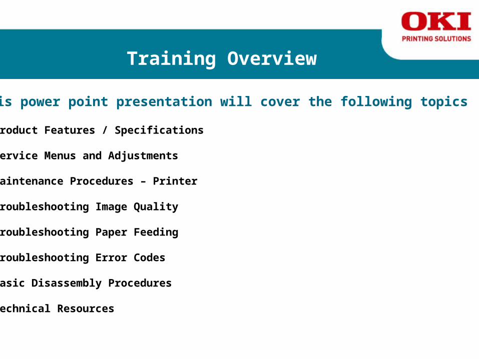
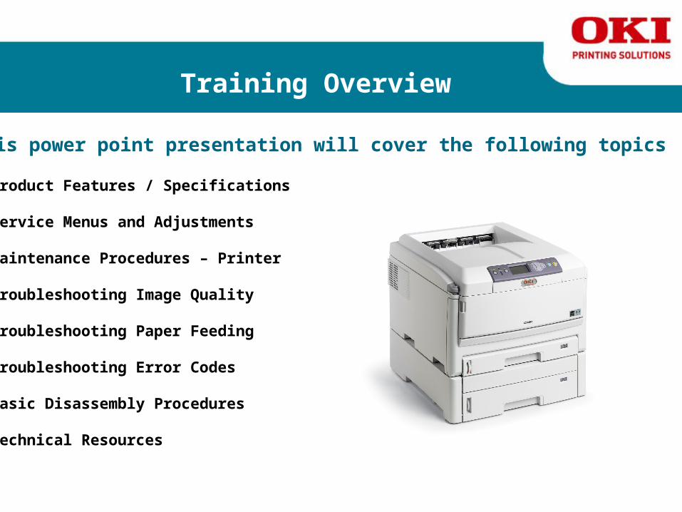
Training Overview
This power point presentation will cover the following topics
► Product Features / Specifications
► Service Menus and Adjustments
► Maintenance Procedures – Printer
► Troubleshooting Image Quality
► Troubleshooting Paper Feeding
► Troubleshooting Error Codes
► Basic Disassembly Procedures
► Technical ResourcesC710 Printer

Training Resources
What you will need to complete this course.
The following training presentation is based on the:
Click Here Click Here
C710 Service Manual C710 Parts Manual
Click on the link to select the document

Training Resources
The following training presentation is also based on the:
OKI Product Knowledgebase for the C710 Color Printer.
C710 User’s Manual
C710 Network User Guide
C710 Handy Reference Guide
C710 Setup Guide
Click on the link to select the document

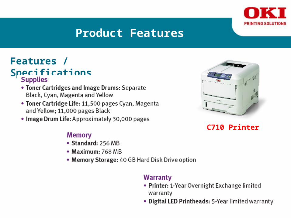
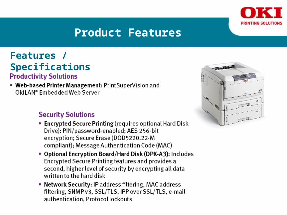
Product Features
Features / Specifications
C710 Printer

Product Features
Features / Specifications
C710 Printer

Product Features
Features / Specifications
C710 Printer

Product Features
Features / Specifications
C710 Printer

Product Features
Features / Specifications
C710 Printer
Product Features
Features / Specifications
C710 Printer
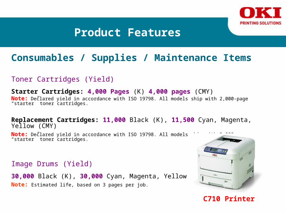
Product Features
Consumables / Supplies / Maintenance Items
Toner Cartridges (Yield)
Starter Cartridges: 4,000 Pages (K) 4,000 pages (CMY)Note: Declared yield in accordance with ISO 19798. All models ship with 2,000-page “starter” toner cartridges.
Replacement Cartridges: 11,000 Black (K), 11,500 Cyan, Magenta, Yellow (CMY) Note: Declared yield in accordance with ISO 19798. All models ship with 2,000-page “starter” toner cartridges.
Image Drums (Yield)
30,000 Black (K), 30,000 Cyan, Magenta, Yellow (CMY) Note: Estimated life, based on 3 pages per job.
C710 Printer
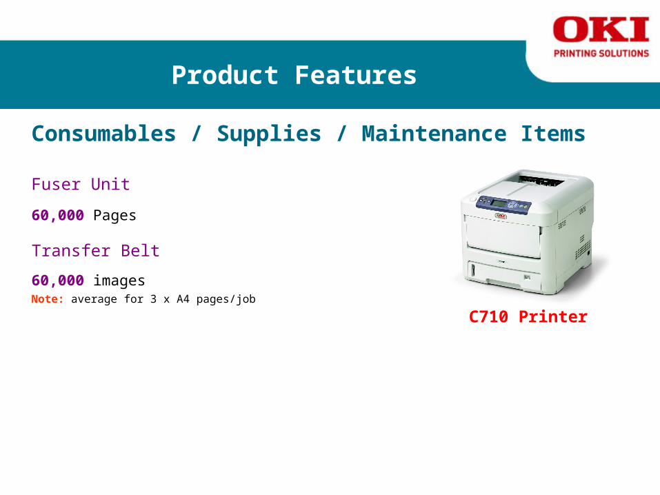
Product Features
Consumables / Supplies / Maintenance Items
Fuser Unit 60,000 Pages
Transfer Belt 60,000 images Note: average for 3 x A4 pages/job
C710 Printer

Product Features
Optional Accessories
40 GB Hard Drive
256GB Memory
512GB Memory
Duplex Unit530 Sheet 2nd/3rd Tray
Storage Cabinet

Service Menus and Adjustments
The C710 can be adjusted through the User & Service Menus. Adjustments are accessed through the Maintenance Utility.
User Maintenance Menu
Refer to the C710 Printer Maintenance Manual page 91 for full details
System Maintenance Menu
Refer to the C710 Printer Maintenance Manual page 92 for full details
Maintenance Utility
Refer to the C710 Printer Maintenance Manual page 95 for full details
Manual Density Adjustment
Refer to the C710 Printer Maintenance Manual page 116 for full details
Setup After Part Replacement
Refer to the C710 Printer Maintenance Manual page 114 for full details
C710 Service Manual Click on the link to select the document

Maintenance Procedures
Maintenance Procedures for the Printer include the following:
► Exterior Cleaning ►Cleaning the LED Lens Array ► Cleaning the Pickup Roller ► Cleaning Inside the Printer
Refer to the C710 Printer Maintenance Manual page 118 for full details
Click on the link to select the document C710 Service Manual

Troubleshooting Image Quality
Basic Image Quality Troubleshooting
Image-quality defects can be attributed to printer components, consumables, media, internal software, external software applications, and environmental conditions. To successfully troubleshoot image-quality problems, eliminate as many variables as possible. The first step is to generate prints using printable pages embedded in the printer on paper from the Supported Media List. Use paper from a fresh, unopened ream that is acclimated to room temperature and humidity. If the print-quality defect is still present when printing on approved media, then investigate software applications and environmental conditions.
The printer uses separate Imaging Units to develop a latent image for each color where the colors are combined on the Transfer Unit to form the final image. In most cases, image-quality defects are the result of one particular component in the print engine. When a single component of the Imaging Unit is causing a print quality defect, replace the Imaging Unit.
When analyzing an image-quality defect, first determine if the defect occurs in all colors or only one color and if it is repeating or random. Continuous defects in the process direction, such as voids and lines, are the most difficult to diagnose. Inspect the visible surfaces of all rollers for obvious defects. If no defects are observed, replace the Imaging Units, Transfer Unit, and Fuser one at a time until the defect is eliminated.
See page 180 in the Service Manual for full detailsClick on the link to select the document C710 Service Manual

Troubleshooting Paper Feeding
Troubleshooting Paper Feeding The Maintenance Manual contains specific paper jam troubleshooting details for various paperfeeding issues as illustrated. Please refer to the Maintenance Manual for specific paper jamcodes and troubleshooting details.
See page 159 in the Service Manual for full details
C710 Service Manual
Click on the link to select the document

Troubleshooting Error Codes
Troubleshooting Error Codes The Maintenance Manual contains specific Self Diagnostic Error Code troubleshooting details for various areas of the printer & scanner as illustrated. Please refer to the MaintenanceManual for specific Self Diagnostic Error codes and troubleshooting details.
See page 172 in the Service Manual for full details
C710 Service Manual
Click on the link to select the document

Basic Disassembly Procedures
What you will need to complete this section of the course.
Click Here
C710 Service Manual
Click on the link to select the document

Basic Disassembly Procedures
Basic Disassembly Procedures
The Service Manual details component locations in the printer and fully illustrated printer disassembly instructions for:
► Covers
► Paper Feed Components
► Internal Printer Components
► Electrical Components
See pages 61 through 98 in the Service Manual for full details
Click on the link to select the document C710 Service Manual

Basic Disassembly Procedures
Basic Disassembly Procedures
The following videos detail component locations in the printer and fully illustrated printer disassembly for:
► LED Head► Left Cover ► Right Cover
►Face Up Tray► Main Controller Board► Engine Board► Top Cover► Control Panel► Low Voltage Power Supply► AC Inlet / ID Motor► Color Registration Assembly► Eject Assembly► Belt Motor► MPT Tray Assembly► Hopping Cover
Windows Media Player must be installed to view this video
Basic Disassembly Procedures
Removing the LED Heads

Windows Media Player must be installed to view this video
Basic Disassembly Procedures
Removing the Left Cover

Windows Media Player must be installed to view this video
Basic Disassembly Procedures
Removing the Right Cover

Windows Media Player must be installed to view this video
Basic Disassembly Procedures
Removing the Face Up Tray

Windows Media Player must be installed to view this video
Basic Disassembly Procedures
Removing the Main Control Board

Windows Media Player must be installed to view this video
Basic Disassembly Procedures
Removing the Engine Board

Windows Media Player must be installed to view this video
Basic Disassembly Procedures
Removing the Top Cover Assembly

Windows Media Player must be installed to view this video
Basic Disassembly Procedures
Removing the Control Panel

Windows Media Player must be installed to view this video
Basic Disassembly Procedures
Removing the Low Voltage Power Supply

Windows Media Player must be installed to view this video
Basic Disassembly Procedures
Removing the AC Inlet / ID Motor

Windows Media Player must be installed to view this video
Basic Disassembly Procedures
Removing the Color Registration Assembly

Windows Media Player must be installed to view this video
Basic Disassembly Procedures
Removing the Eject Assembly

Windows Media Player must be installed to view this video
Basic Disassembly Procedures
Removing the Belt Motor

Windows Media Player must be installed to view this video
Basic Disassembly Procedures
Removing the MPT Assembly

Windows Media Player must be installed to view this video
Basic Disassembly Procedures
Removing the Hopping Cover

Technical Resources
Tools Available on the Oki Data BPX Website
Click Here Click Here
C710 Service Manual C710 Parts Manual
Click on the link to select the document

Technical Resources
Tools Available on the Oki Data BPX Website
OKI Product Knowledgebase for the C710 Color Printer.
C710 User’s Manual
C710 Network User Guide
C710 Handy Reference Guide
C710 Setup Guide
Click on the link to select the document
Thank you
Thank you for completing this
C710 Printer TrainingYou now can confidently set-up this product and perform basic troubleshooting.
Now on to the: C830 Printer

The C830 Printer
Training Overview
This power point presentation will cover the following topics
► Product Features / Specifications
► Service Menus and Adjustments
► Maintenance Procedures – Printer
► Troubleshooting Image Quality
► Troubleshooting Paper Feeding
► Troubleshooting Error Codes
► Basic Disassembly Procedures
► Technical Resources

Training Resources
What you will need to complete this course.
The following training presentation is based on the:
Click Here
Click Here
C830 Service Manual C830 Parts Manual
Click on the link to select the document

Training Resources
The following training presentation is also based on the:
OKI Product Knowledgebase for the C830 Color Printer
C830 User’s Manual
C830 Network User Guide
C830 Handy Reference Guide
C830 Setup Guide
Click on the link to select the document

Product Features
Features / Specifications

Product Features
Features / Specifications

Product Features
Features / Specifications
Product Features
Features / Specifications

Product Features
Features / Specifications
Product Features
Features / Specifications
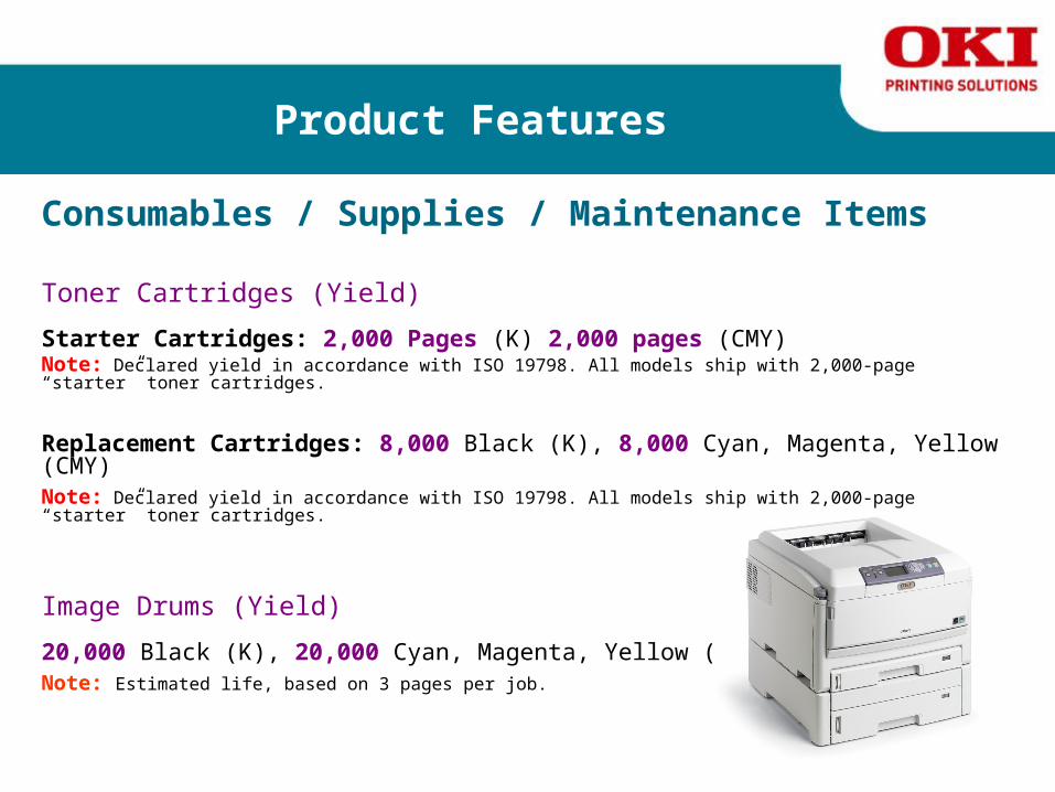
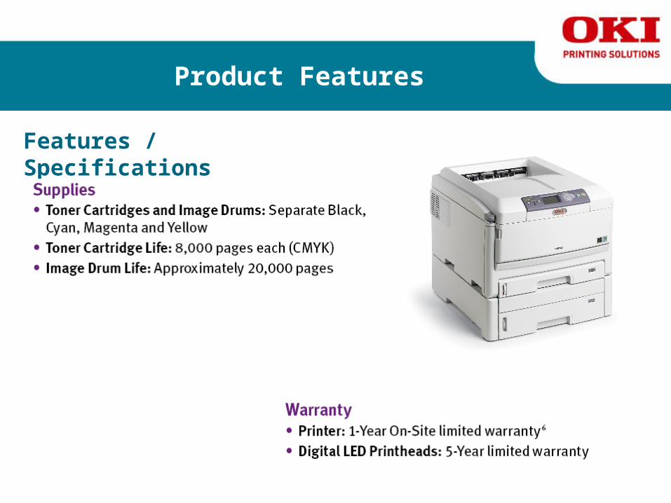
Product Features
Consumables / Supplies / Maintenance Items
Toner Cartridges (Yield)
Starter Cartridges: 2,000 Pages (K) 2,000 pages (CMY)Note: Declared yield in accordance with ISO 19798. All models ship with 2,000-page “starter” toner cartridges.
Replacement Cartridges: 8,000 Black (K), 8,000 Cyan, Magenta, Yellow (CMY) Note: Declared yield in accordance with ISO 19798. All models ship with 2,000-page “starter” toner cartridges.
Image Drums (Yield)
20,000 Black (K), 20,000 Cyan, Magenta, Yellow (CMY) Note: Estimated life, based on 3 pages per job.

Product Features
Consumables / Supplies / Maintenance Items
Fuser Unit 60,000 Pages
Transfer Belt 60,000 images Note: average for 3 x A4 pages/job
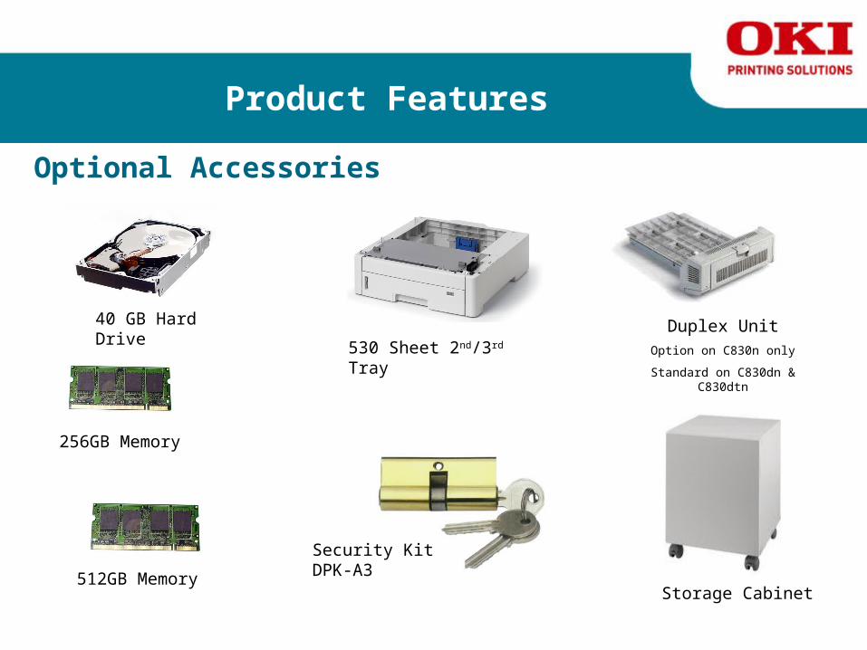
Product Features
Optional Accessories
40 GB Hard Drive
256GB Memory
512GB Memory
Duplex UnitOption on C830n only
Standard on C830dn & C830dtn
530 Sheet 2nd/3rd Tray
Storage Cabinet
Security Kit DPK-A3

Service Menus and Adjustments
The C830 can be adjusted through the User & Service Menus. Adjustments are accessed through the Maintenance Utility.
User Maintenance Menu
Refer to the C830 Printer Maintenance Manual pages 124 through 126 for full details
System Maintenance Menu
Refer to the C830 Printer Maintenance Manual pages 120 through 121 for full details
Maintenance Utility
Refer to the C830 Printer Maintenance Manual pages 122 through 123 for full details
Manual Density Adjustment
Refer to the C830 Printer Maintenance Manual page 148 for full details
Setup After Part Replacement
Refer to the C830 Printer Maintenance Manual pages 146 through 147 for full details
C830 Service Manual Click on the link to select the document
Maintenance Procedures
Maintenance Procedures for the Printer include the following:
► Exterior Cleaning ►Cleaning the LED Lens Array ► Cleaning the Pickup Roller ► Cleaning Inside the Printer
Refer to the C830 Printer Maintenance Manual pages 151 through 155 for full details
Click on the link to select the document C830 Service Manual
Troubleshooting Image Quality
Basic Image Quality Troubleshooting
Image-quality defects can be attributed to printer components, consumables, media, internal software, external software applications, and environmental conditions. To successfully troubleshoot image-quality problems, eliminate as many variables as possible. The first step is to generate prints using printable pages embedded in the printer on paper from the Supported Media List. Use paper from a fresh, unopened ream that is acclimated to room temperature and humidity. If the print-quality defect is still present when printing on approved media, then investigate software applications and environmental conditions.
The printer uses separate Imaging Units to develop a latent image for each color where the colors are combined on the Transfer Unit to form the final image. In most cases, image-quality defects are the result of one particular component in the print engine. When a single component of the Imaging Unit is causing a print quality defect, replace the Imaging Unit.
When analyzing an image-quality defect, first determine if the defect occurs in all colors or only one color and if it is repeating or random. Continuous defects in the process direction, such as voids and lines, are the most difficult to diagnose. Inspect the visible surfaces of all rollers for obvious defects. If no defects are observed, replace the Imaging Units, Transfer Unit, and Fuser one at a time until the defect is eliminated.
See pages 211 through 217 in the Service Manual for full detailsC830 Service Manual Click on the link to select the document

Troubleshooting Paper Feeding
Troubleshooting Paper Feeding The Maintenance Manual contains specific paper jam troubleshooting details for various paperfeeding issues as illustrated. Please refer to the Maintenance Manual for specific paper jamcodes and troubleshooting details.
See pages 180 through 209 in the Service Manual for full details
C830 Service Manual
Click on the link to select the document
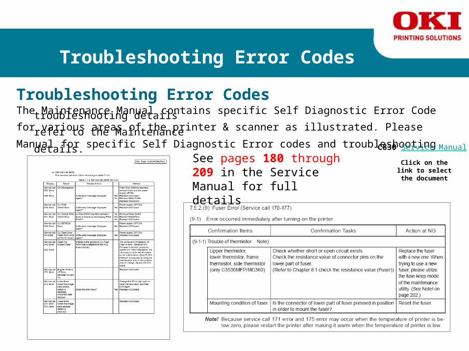
Troubleshooting Error Codes
Troubleshooting Error Codes The Maintenance Manual contains specific Self Diagnostic Error Code troubleshooting details for various areas of the printer & scanner as illustrated. Please refer to the MaintenanceManual for specific Self Diagnostic Error codes and troubleshooting details.
See pages 180 through 209 in the Service Manual for full details
C830 Service Manual
Click on the link to select the document

Basic Disassembly Procedures
What you will need to complete this section of the course.
Click Here
C830 Service Manual
Click on the link to select the document

Basic Disassembly Procedures
Basic Disassembly Procedures
The Service Manual details component locations in the printer and fully illustrated printer disassembly instructions for:
► Covers
► Paper Feed Components
► Internal Printer Components
► Electrical Components
See pages 61 through 98 in the Service Manual for full details
C830 Service Manual Click on the link to select the document

Basic Disassembly Procedures
Basic Disassembly Procedures
The following videos detail component locations in the printer and fully illustrated printer disassembly for:
► LED Head► Rear Cover (Left & Right)► Shield Plate► Main Controller Board► Engine Board► ID Motor/Lift & Paper Feed► Upper Cover► Control Panel Assembly► Guide Assembly (Upper & Lower)► Colour Registration Assembly► Transit PCB► Fuser Fan & HV PSU► MPT Assembly► Registration Roller Assembly► LV PSU► Belt Motor & Fuser Motor

Windows Media Player must be installed to view this video
Basic Disassembly Procedures
Click on the Oki Logo to play the video
Removing the LED Heads

Windows Media Player must be installed to view this video
Basic Disassembly Procedures
Click on the Oki Logo to play the video
Removing the Left, Right and Rear Cover

Windows Media Player must be installed to view this video
Basic Disassembly Procedures
Click on the Oki Logo to play the video
Removing the Shield Plate

Windows Media Player must be installed to view this video
Basic Disassembly Procedures
Click on the Oki Logo to play the video
Removing the Main Control Board

Windows Media Player must be installed to view this video
Basic Disassembly Procedures
Click on the Oki Logo to play the video
Removing the Engine Board

Windows Media Player must be installed to view this video
Basic Disassembly Procedures
Click on the Oki Logo to play the video
Removing the ID Motor / Lift and Paper Feed

Windows Media Player must be installed to view this video
Basic Disassembly Procedures
Click on the Oki Logo to play the video
Removing the Upper Cover

Windows Media Player must be installed to view this video
Basic Disassembly Procedures
Click on the Oki Logo to play the video
Removing the Control Panel

Windows Media Player must be installed to view this video
Basic Disassembly Procedures
Click on the Oki Logo to play the video
Removing the Upper & Lower Guide Assembly

Windows Media Player must be installed to view this video
Basic Disassembly Procedures
Click on the Oki Logo to play the video
Removing the Color Registration Assembly

Windows Media Player must be installed to view this video
Basic Disassembly Procedures
Click on the Oki Logo to play the video
Removing the Transit PCB

Windows Media Player must be installed to view this video
Basic Disassembly Procedures
Click on the Oki Logo to play the video
Removing the Fuser Fan & High Voltage Power Supply

Windows Media Player must be installed to view this video
Basic Disassembly Procedures
Click on the Oki Logo to play the video
Removing the MPT Assembly

Windows Media Player must be installed to view this video
Basic Disassembly Procedures
Click on the Oki Logo to play the video
Removing the Registration Roller Assembly
Windows Media Player must be installed to view this video
Basic Disassembly Procedures
Click on the Oki Logo to play the video
Removing the Low Voltage Power Supply

Windows Media Player must be installed to view this video
Basic Disassembly Procedures
Click on the Oki Logo to play the video
Removing the Belt Motor & Fuser Motor

Technical Resources
Tools Available on the Oki Data BPX Website
Click Here
Click Here
C830 Service Manual C830 Parts Manual
Click on the link to select the document

Technical Resources
Tools Available on the Oki Data BPX Website
OKI Product Knowledgebase for the C830 Color Printer
C830 User’s Manual
C830 Network User Guide
C830 Handy Reference Guide
C830 Setup Guide
Click on the link to select the document
Thank you for completing this
C830 Printer TrainingYou now can confidently set-up this product and perform basic troubleshooting.
Now on to the
Desktop Color Printer EXAM!


