Page 1
Scaling relationships for strip fibre reinforced aggregates
Olufemi Ajayi
Louis Le Pen
Antonis Zervos
William Powrie
Faculty of Engineering and the Environment, University of Southampton, Southampton SO17 1BJ, United Kingdom
23 November 2016
Page 2
Abstract
Previous research on random fibre reinforced granular materials has shown that the relative dimensions of the
grains and fibres significantly affect the macro-mechanical behaviour of the mixture. However, quantitative data
are scarce and most previous work has focused on fine to medium sands, leaving uncertainties regarding the
applicability of current knowledge to larger size aggregates such as railway ballast. In this paper, triaxial test data
on 1/3 and 1/5 scale railway ballast are used to develop scaling relationships for the size and quantity of fibres
needed to achieve the same reinforcing effect in granular materials of differing grain size. It is shown that, to
maintain consistency across scales, fibre content should be quantified as a numerical (i.e. number of fibres per
grain) rather than a volumetric ratio. It is further shown that increasing the fibre length increases the resistance
of the mixture to deviator stress if the fibres are wide enough; and that provided an allowance is made for the
effect of fibre tension, the changes in the stress-strain-strength behaviour of the granular matrix resulting from
the changes in void ratio associated with the addition of the fibres are consistent with conventional soil
mechanics theory across scales.
Keywords: Fibre reinforcements, Granular materials, Railway ballast, Scaling relationships
Page 3
List of symbols
D50 - mean grain size
e - void ratio
Ef - fibre Young’s modulus
ID - density index
Lf - fibre length
LN - normalized length
Nf - number of individual fibres
Nfg - fibre:grain ratio
Ng - average number of grains
p - mean effective stress
p″ - corrected mean effective stress
q - deviator stress
q″ - corrected deviator stress
tf - fibre thickness
Vf - volume of fibres
Vfr - volumetric fibre ratio
Vs - volume of the grains (or “solids”)
Vv - volume of voids
Wf - fibre width
WN - normalized width
α - fibre/grain interaction factor
εa - axial strain
εr - radial strain
εvol - volumetric strain
η - stress ratio
σ′3 - radial stress
σ″3 - corrected lateral stress
σ′f - additional lateral stress
Page 4
1
Introduction and background
It is well-known that the strength and ductility of a sand can be improved by the addition of randomly-distributed
fabric, polymer or metal fibres (e.g. Michalowski and Cermak, 2002; Lirer et al., 2011; Diambra et al., 2013). Initial
tests on much larger-grained, scaled and full-sized railway ballast show similar promise (Abadi, 2015). The
mechanical behaviour of the reinforced material depends on the properties of both the fibres and the grains, as
well as their relative sizes and proportions (e.g. Michalowski and Cermak, 2003; Sadek et al., 2010).
Michalowski (1997) identified two alternative sand-fibre interaction mechanisms, related to the relative effective
diameters of the grains and the fibres:
1. Where the representative diameter of the soil grains D50 (the median grain size of soil by weight) is small
in comparison with the effective fibre diameter Df, the number of grain contacts area for an individual
fibre is relatively large and the frictional fibre-grain matrix interface may be considered continuous. This is
the approach used with soil nails, which may be viewed as a particular case of soil reinforcement. It is
termed short fibre reinforcement by Michalowski (1997), although the real point is that the fibre diameter is
larger than the typical grain size, i.e. DN = Df/D50 > 1, where DN is the normalised fibre diameter:
2. Where the diameter of the fibre is at least an order of magnitude smaller than the median grain size, i.e.
DN < 0.1, individual contacts and the way in which the fibres fit into the pore space may need to be
considered at the grain scale. This is termed continuous thin filament fibre reinforcement by Michalowski (1997).
Michalowski (1997) also states that this mechanism of reinforcement relies on the development of a force
in each fibre as a result of a “belt-friction effect”, as the fibre wraps around the grains. The fibre must
therefore be rather longer than the typical grain size, i.e. Lf >> D50, where Lf is the fibre length. Allowing
for a fibre to wrap fully round two adjacent grains requires Lf > (2 + 1) × D50. This is approximately
one order of magnitude, implying LN = Lf/D50 ≥ 10, where LN is the normalised fibre length.
It is clear from the foregoing that, notwithstanding the nomenclature adopted by Michalowski (1997), the
mechanism of fibre reinforcement depends on the length and thickness of the fibres relative to the grains, as well
as on the amount of fibres present and their bending stiffness. The aim of this paper is to develop the
understanding of the impacts of the relative fibre:grain dimensions and the proportion of fibres present on the
mechanical behaviour of a coarse granular material, in the context of using fibre reinforcement to improve the
performance of a scaled railway ballast.
Page 5
2
Ballast is a main component of a traditional railway track system. It resists and distributes the vertical, lateral and
longitudinal forces applied to the track by trains as they pass, curve, brake and accelerate. In response to the many
millions of loading cycles it experiences, ballast generally undergoes gradual plastic settlement. Such settlement,
especially if it is differential, causes a loss of track geometry (level and line) and can result in the imposition of
speed restrictions and/or a requirement for emergency remediation. The benefits of using geogrids to reinforce
railway ballast, in reducing both lateral spread and vertical settlement, are reasonably well established (e.g. Bathurst
and Raymond, 1987; McDowell et al., 2006; Indraratna et al., 2010; Indraratna et al., 2011). However, a drawback
of that approach is the restriction it imposes on future maintenance activities - particularly tamping, which would
disrupt or destroy the geogrids if they were placed in the tamped zone. The addition of randomly distributed
synthetic fibres could provide an alternative way of reinforcing ballast that is able to withstand typical tamping
operations, permitting reinforcement through the full depth.
Although some results from a well-graded gravel with grain sizes in the range 0.2 – 10 mm were reported by Lirer
et al. (2011), research on fibre reinforced granular materials has to date focused mainly on fine to medium sands.
Thus neither the effect of fibre reinforcement on larger grained aggregates, nor the relevant underlying
mechanisms of grain-fibre interaction have been fully investigated. It is reasonable to expect that both the effects
and the micromechanics will be similar, provided that the fibre dimensions are appropriately scaled to account for
the larger grain size. However, the ways in which the fibre-grain interactions influence the improvement in sand
behaviour scale with grain size are uncertain.
This paper reports the results of an investigation into the mechanical properties of fibre reinforced granular
materials representing 1⁄3 and 1⁄5 scale railway ballast. Particular emphasis is placed on the effects of fibre content,
as well as the relative dimensions of the fibres and grains, for the different grain size ranges. Relationships are
developed for the size and quantity of fibres required to achieve the same reinforcing effect in granular materials
of different grain sizes.
Experimental work
Materials
Testing of scaled ballast (SB) offers an attractive way of developing an understanding of the mechanics of the full
size material. Direct testing of the latter is difficult and can be unreliable, owing to the challenges that the large
grain size creates for laboratory element tests. For a given aggregate, measurable variations in grain shape occur
Page 6
3
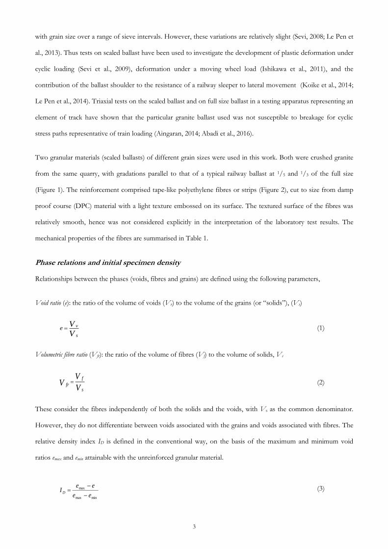
with grain size over a range of sieve intervals. However, these variations are relatively slight (Sevi, 2008; Le Pen et
al., 2013). Thus tests on scaled ballast have been used to investigate the development of plastic deformation under
cyclic loading (Sevi et al., 2009), deformation under a moving wheel load (Ishikawa et al., 2011), and the
contribution of the ballast shoulder to the resistance of a railway sleeper to lateral movement (Koike et al., 2014;
Le Pen et al., 2014). Triaxial tests on the scaled ballast and on full size ballast in a testing apparatus representing an
element of track have shown that the particular granite ballast used was not susceptible to breakage for cyclic
stress paths representative of train loading (Aingaran, 2014; Abadi et al., 2016).
Two granular materials (scaled ballasts) of different grain sizes were used in this work. Both were crushed granite
from the same quarry, with gradations parallel to that of a typical railway ballast at 1/5 and 1/3 of the full size
(Figure 1). The reinforcement comprised tape-like polyethylene fibres or strips (Figure 2), cut to size from damp
proof course (DPC) material with a light texture embossed on its surface. The textured surface of the fibres was
relatively smooth, hence was not considered explicitly in the interpretation of the laboratory test results. The
mechanical properties of the fibres are summarised in Table 1.
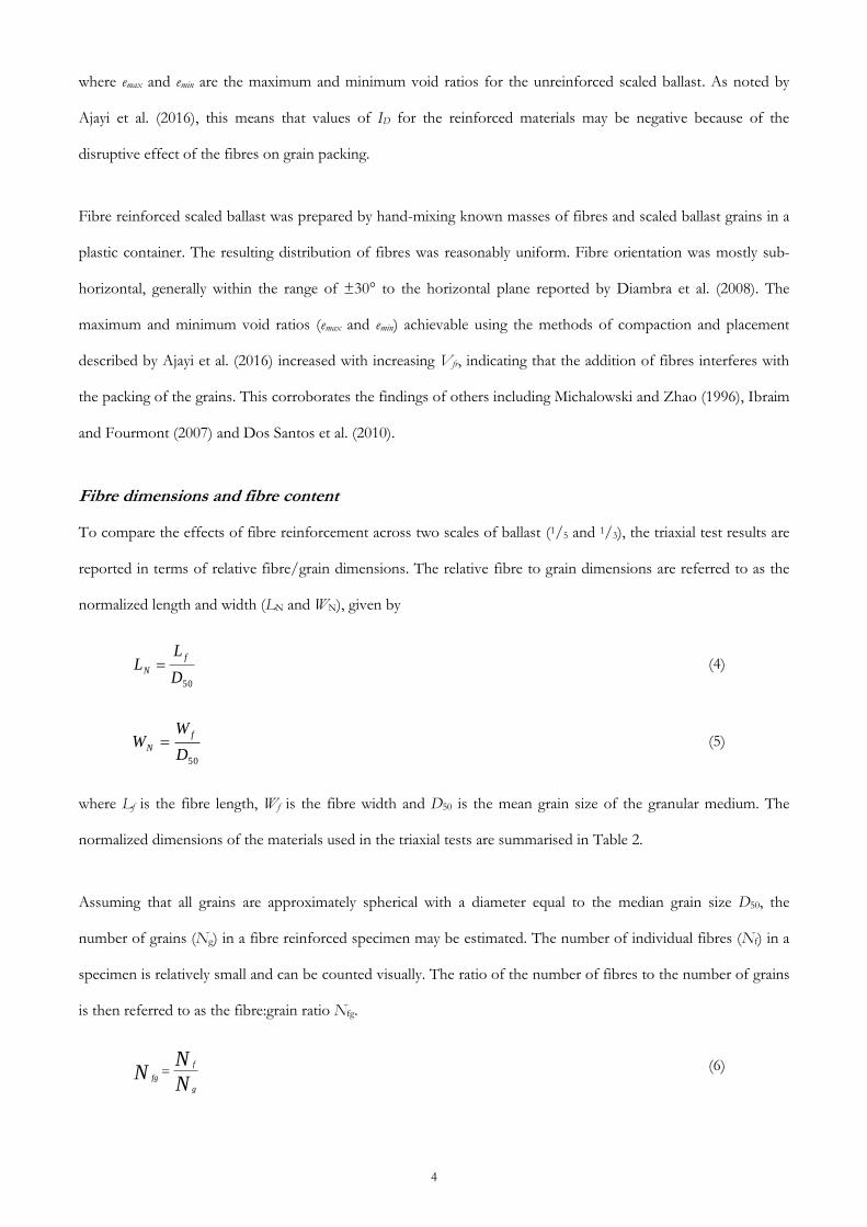
Phase relations and initial specimen density
Relationships between the phases (voids, fibres and grains) are defined using the following parameters,
Void ratio (e): the ratio of the volume of voids (Vv) to the volume of the grains (or “solids”), (Vs)
V
V
s
ve (1)
Volumetric fibre ratio (Vfr): the ratio of the volume of fibres (Vf) to the volume of solids, Vs
V
VV
s
f
fr (2)
These consider the fibres independently of both the solids and the voids, with Vs as the common denominator.
However, they do not differentiate between voids associated with the grains and voids associated with fibres. The
relative density index ID is defined in the conventional way, on the basis of the maximum and minimum void
ratios emax and emin attainable with the unreinforced granular material.
minmax
max
ee
eeI D
(3)
Page 7
4
where emax and emin are the maximum and minimum void ratios for the unreinforced scaled ballast. As noted by
Ajayi et al. (2016), this means that values of ID for the reinforced materials may be negative because of the
disruptive effect of the fibres on grain packing.
Fibre reinforced scaled ballast was prepared by hand-mixing known masses of fibres and scaled ballast grains in a
plastic container. The resulting distribution of fibres was reasonably uniform. Fibre orientation was mostly sub-
horizontal, generally within the range of ±30° to the horizontal plane reported by Diambra et al. (2008). The
maximum and minimum void ratios (emax and emin) achievable using the methods of compaction and placement
described by Ajayi et al. (2016) increased with increasing Vfr, indicating that the addition of fibres interferes with
the packing of the grains. This corroborates the findings of others including Michalowski and Zhao (1996), Ibraim
and Fourmont (2007) and Dos Santos et al. (2010).
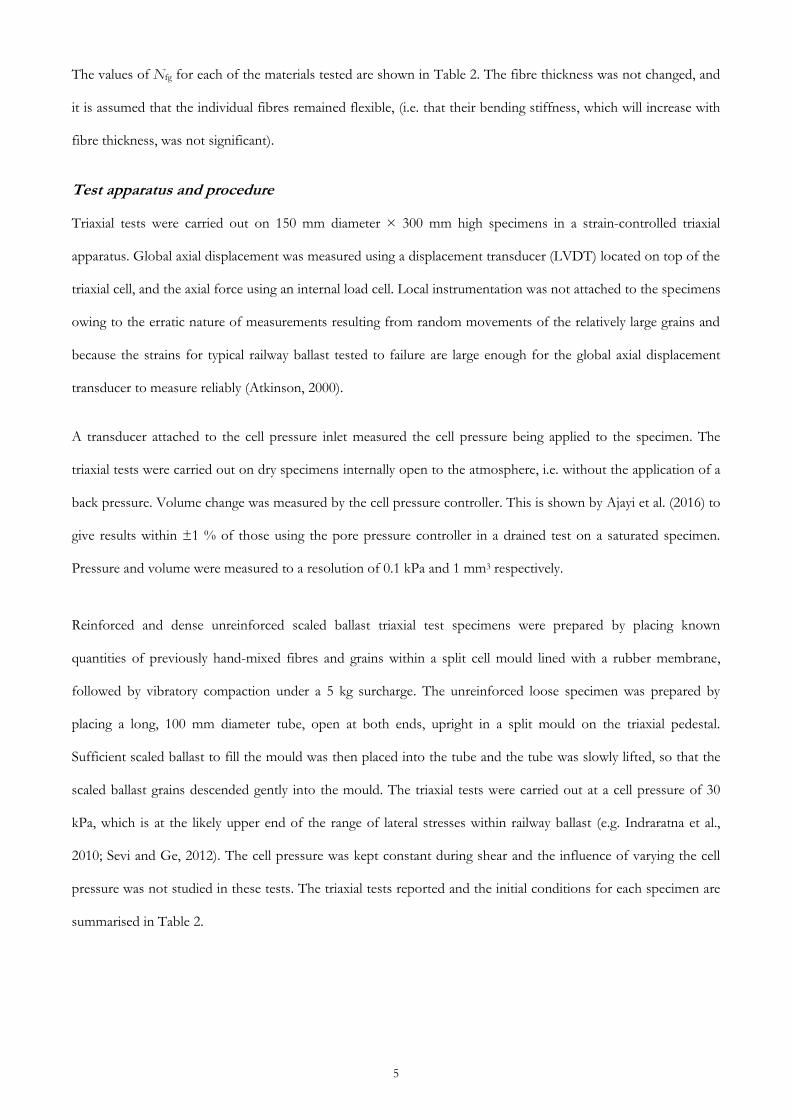
Fibre dimensions and fibre content
To compare the effects of fibre reinforcement across two scales of ballast (1/5 and 1/3), the triaxial test results are
reported in terms of relative fibre/grain dimensions. The relative fibre to grain dimensions are referred to as the
normalized length and width (LN and WN), given by
50D
LL
f
N (4)
50D
WW
f
N (5)
where Lf is the fibre length, Wf is the fibre width and D50 is the mean grain size of the granular medium. The
normalized dimensions of the materials used in the triaxial tests are summarised in Table 2.
Assuming that all grains are approximately spherical with a diameter equal to the median grain size D50, the
number of grains (Ng) in a fibre reinforced specimen may be estimated. The number of individual fibres (Nf) in a
specimen is relatively small and can be counted visually. The ratio of the number of fibres to the number of grains
is then referred to as the fibre:grain ratio Nfg.
N
NN
g
f
fg (6)
Page 8
5
The values of Nfg for each of the materials tested are shown in Table 2. The fibre thickness was not changed, and
it is assumed that the individual fibres remained flexible, (i.e. that their bending stiffness, which will increase with
fibre thickness, was not significant).
Test apparatus and procedure
Triaxial tests were carried out on 150 mm diameter × 300 mm high specimens in a strain-controlled triaxial
apparatus. Global axial displacement was measured using a displacement transducer (LVDT) located on top of the
triaxial cell, and the axial force using an internal load cell. Local instrumentation was not attached to the specimens
owing to the erratic nature of measurements resulting from random movements of the relatively large grains and
because the strains for typical railway ballast tested to failure are large enough for the global axial displacement
transducer to measure reliably (Atkinson, 2000).
A transducer attached to the cell pressure inlet measured the cell pressure being applied to the specimen. The
triaxial tests were carried out on dry specimens internally open to the atmosphere, i.e. without the application of a
back pressure. Volume change was measured by the cell pressure controller. This is shown by Ajayi et al. (2016) to
give results within ±1 % of those using the pore pressure controller in a drained test on a saturated specimen.
Pressure and volume were measured to a resolution of 0.1 kPa and 1 mm3 respectively.
Reinforced and dense unreinforced scaled ballast triaxial test specimens were prepared by placing known
quantities of previously hand-mixed fibres and grains within a split cell mould lined with a rubber membrane,
followed by vibratory compaction under a 5 kg surcharge. The unreinforced loose specimen was prepared by
placing a long, 100 mm diameter tube, open at both ends, upright in a split mould on the triaxial pedestal.
Sufficient scaled ballast to fill the mould was then placed into the tube and the tube was slowly lifted, so that the
scaled ballast grains descended gently into the mould. The triaxial tests were carried out at a cell pressure of 30
kPa, which is at the likely upper end of the range of lateral stresses within railway ballast (e.g. Indraratna et al.,
2010; Sevi and Ge, 2012). The cell pressure was kept constant during shear and the influence of varying the cell
pressure was not studied in these tests. The triaxial tests reported and the initial conditions for each specimen are
summarised in Table 2.
Page 9
6
Test results and analysis
Interpretative framework
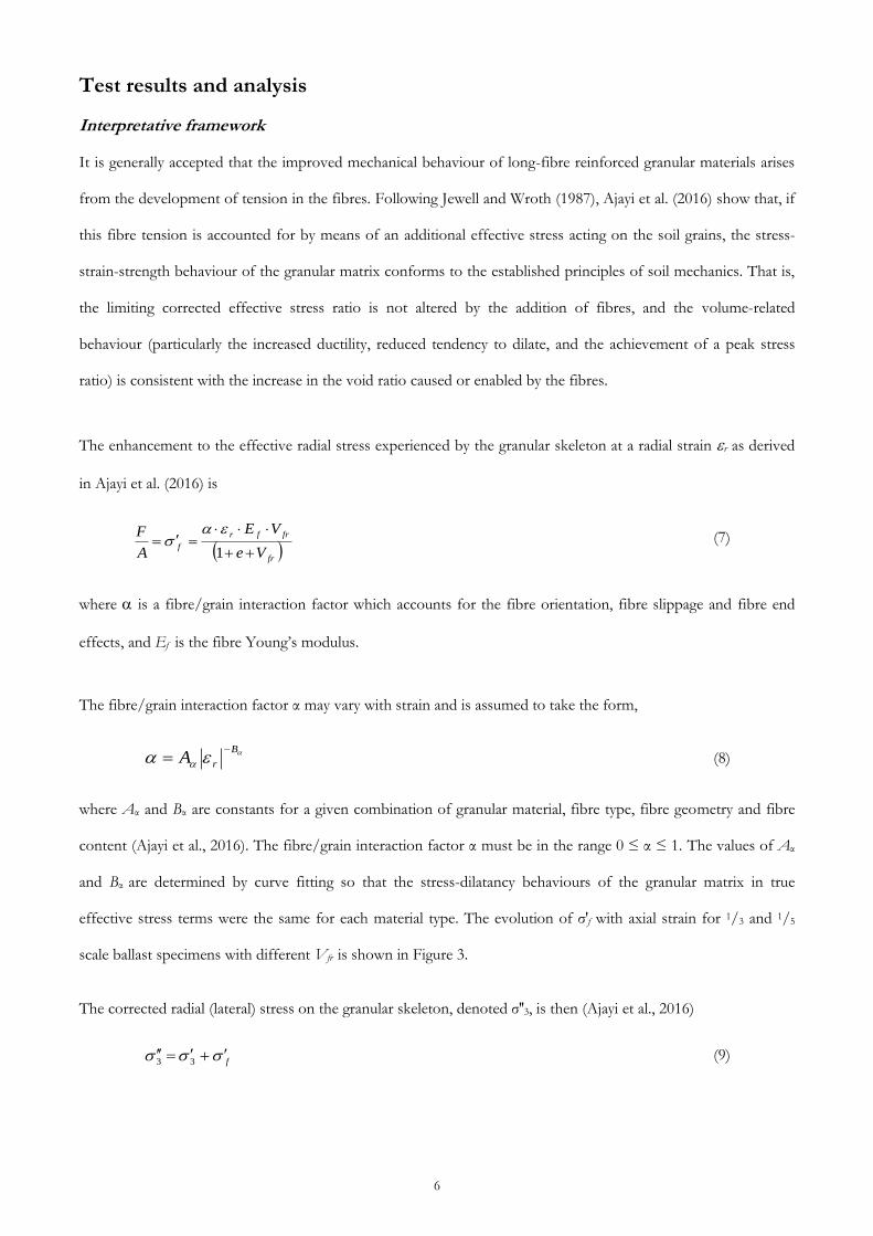
It is generally accepted that the improved mechanical behaviour of long-fibre reinforced granular materials arises
from the development of tension in the fibres. Following Jewell and Wroth (1987), Ajayi et al. (2016) show that, if
this fibre tension is accounted for by means of an additional effective stress acting on the soil grains, the stress-
strain-strength behaviour of the granular matrix conforms to the established principles of soil mechanics. That is,
the limiting corrected effective stress ratio is not altered by the addition of fibres, and the volume-related
behaviour (particularly the increased ductility, reduced tendency to dilate, and the achievement of a peak stress
ratio) is consistent with the increase in the void ratio caused or enabled by the fibres.
The enhancement to the effective radial stress experienced by the granular skeleton at a radial strain r as derived
in Ajayi et al. (2016) is
fr
frfr
fVe
VE
A
F
1
(7)
where is a fibre/grain interaction factor which accounts for the fibre orientation, fibre slippage and fibre end
effects, and Ef is the fibre Young’s modulus.
The fibre/grain interaction factor α may vary with strain and is assumed to take the form,
B
rA
(8)
where Aα and Bα are constants for a given combination of granular material, fibre type, fibre geometry and fibre
content (Ajayi et al., 2016). The fibre/grain interaction factor α must be in the range 0 ≤ α ≤ 1. The values of Aα
and Bα are determined by curve fitting so that the stress-dilatancy behaviours of the granular matrix in true
effective stress terms were the same for each material type. The evolution of σ′f with axial strain for 1/3 and 1/5
scale ballast specimens with different Vfr is shown in Figure 3.
The corrected radial (lateral) stress on the granular skeleton, denoted σ′′3, is then (Ajayi et al., 2016)
f 33 (9)
Page 10
7
This additional effective stress acts only in the radial direction, partly because the axial stress is compressive and it
is assumed that the fibres have no stiffness in compression, and partly because the orientation of the fibres is
substantially horizontal.
The corrected deviator stress, q′′, and the corrected mean effective stress, p′′, then become (Ajayi et al., 2016)
f'qq (10)
'"
3
"
13
22
3
1fpp (11)
However, presenting the results in this way masks the benefit of fibre reinforcement in terms of the increase in
the peak deviator stress achieved. Hence the results will be presented and discussed initially in terms of total
deviator stress, axial and volumetric strain. It must be emphasised that the total deviator stress and the cell
pressure do not reflect the true effective stresses experienced by the granular skeleton. Where appropriate, data are
also presented and discussed in terms of the true effective stresses given by Eqs (10) and (11).
Effects of LN and WN
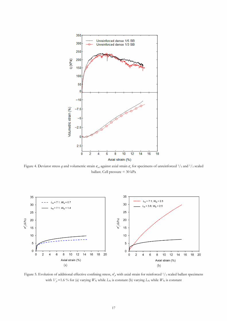
Figure 4 shows graphs of deviator stress q and volumetric strain vol against axial strain a for triaxial tests on
unreinforced 1/5 and 1/3 scale ballast, demonstrating the similiarity in their mechanical behaviour.
Owing to the larger particle sizes being considered in this work, it is reasonable to expect that the influence of the
relative fibre dimensions on the macro-mechanical behaviour will be more pronounced than with a sand. The
effects of changing LN and WN will now be considered.
Figure 5 shows the evolution of the additional effective lateral stress σ′f with axial strain for specimens having
different LN and WN and the same fibre content (Vfr = 1.6%). Figure 5 suggests that increasing WN provided LN is
long enough, or increasing LN provided that WN is wide enough for significant fibre-grain interaction to take place,
will increase the value of σ′f mobilised at a given axial strain greater than about 1%. (At axial strains below 1%,
increasing the fibre length or width has the opposite effect).
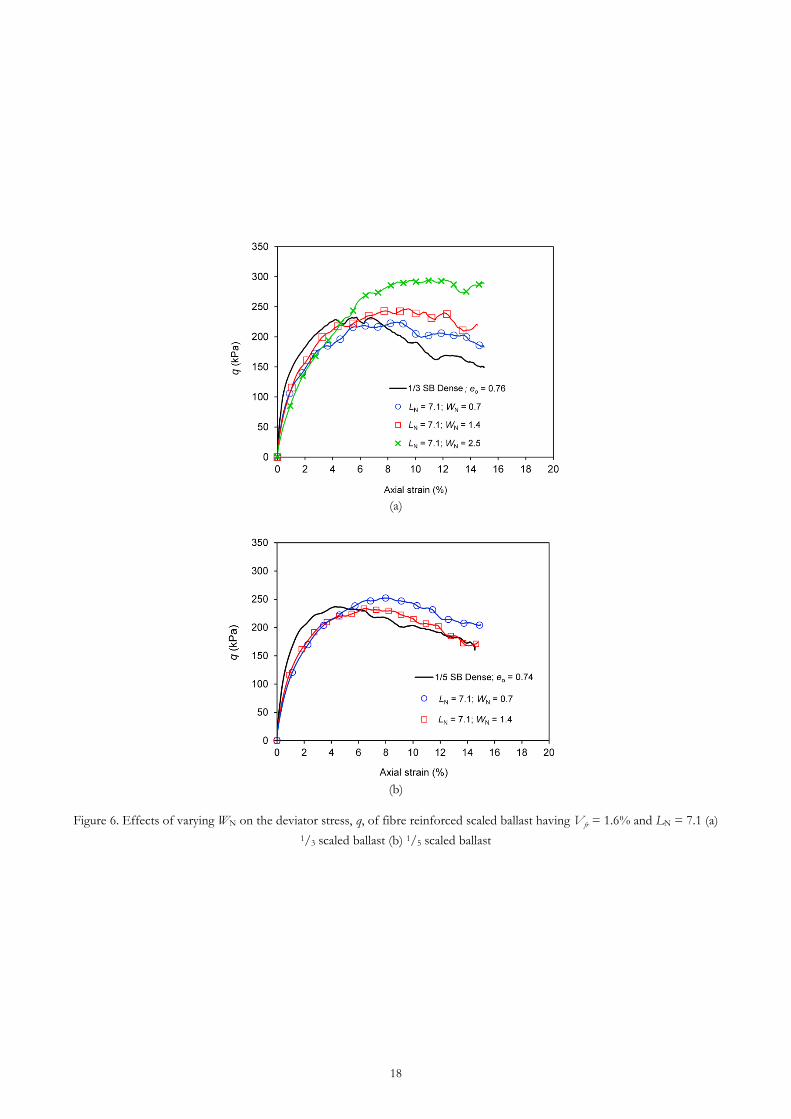
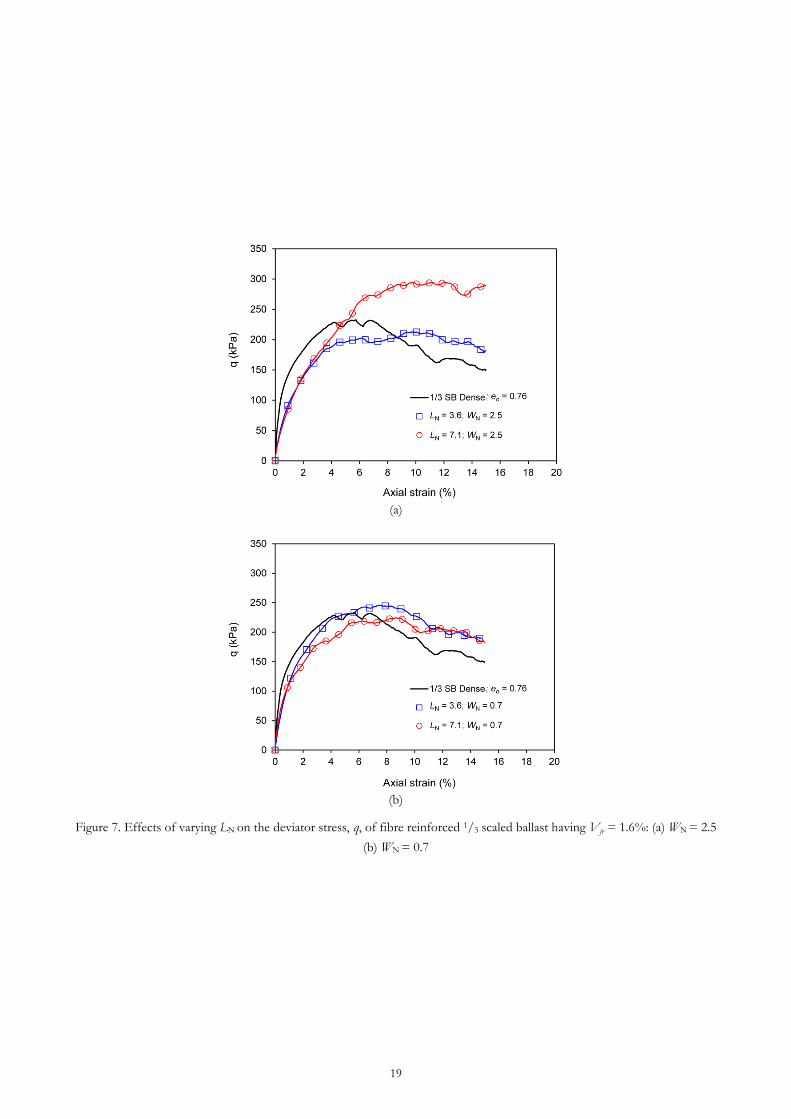
At larger strains, the effect of increasing WN and LN in increasing the mobilised deviator stress at a given axial
strain is clear in Figures 6 and 7. Figure 7b confirms that longer fibres are only beneficial in this respect if WN is
sufficient to ensure adequate fibre-grain contact across the width of the fibre.
Page 11
8
Effects of fibre content - Vfr and Nfg
Figure 8 shows graphs of deviator stress and volumetric strain against axial strain for (a) 1/3 and (b) 1/5 scaled
ballast with different amounts of fibre reinforcement, characterised by volumetric fibre ratios Vfr = 0
(unreinforced), 1.6 % and 3.2 %. For both materials, increasing the amount of reinforcement by fibres of given
normalised dimensions LN and WN delays the occurrence and increases the magnitude of the peak deviator stress,
decreases the initial stiffness, reduces dilation and improves ductility. This behaviour is broadly similar to that
reported by Michalowski and Cermak (2003), Heineck et al. (2005) and Diambra et al. (2010) for reinforced and
unreinforced sand. However, while the mechanical behaviours of reinforced 1/3 and 1/5 scaled ballast follow
qualitatively similar trends with increasing Vfr, quantitatively the effect of a given amount of fibre reinforcements
(i.e. the same Vfr) is different in each case. It follows that Vfr alone is not an appropriate measure of the amount of
fibre reinforcement for the purposes of comparing across grain scales. This may be explained as follows.
At a given Vfr , the number of fibres per grain Nfg increases with the grain size (Figure 9), because the fibre
thickness tf has not been scaled with D50. Thus as the grain size increases, each individual fibre interacts with
fewer grains; and for relatively thin fibres (DN = tf/D50 < 0.1), grain level interactions are the dominant influence
on the macro-mechanical behaviour. This explains the greater shear strength at larger axial strains (when the
tensile force in the fibres is contributing more significantly to the mobilised strength) exhibited by the 1/3 scaled
ballast than the 1/5 scaled ballast specimens in Figure 8.
Better quantitative agreement between the stress ratio (η) and volumetric strain (vol) vs axial strain (a) behaviour
at the two scales is obtained by comparing data from triaxial tests on specimens having similar Nfg, LN and WN
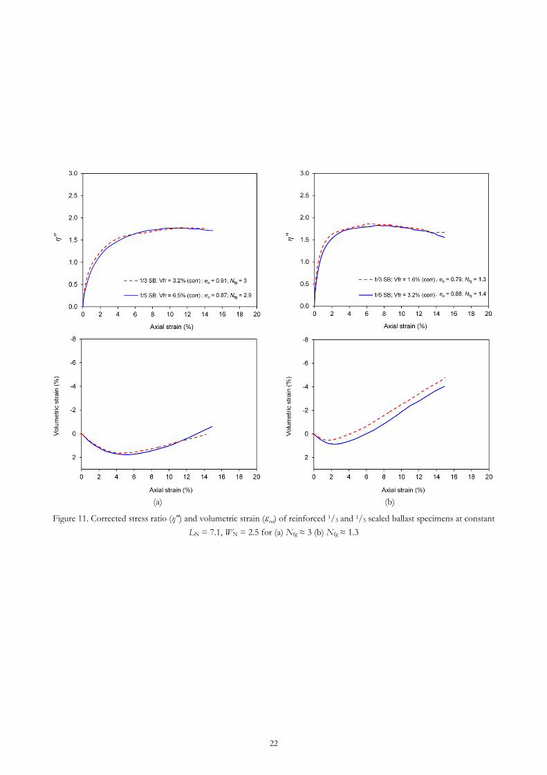
(Figure 10). This better quantitative agreement is also exhibited when the corrected stress ratio (η″) is plotted
against axial strain (a) (Figure 11). As the grain size of the granular material is increased, the number of individual
thin strip fibres required to develop similar macro-mechanical behaviour across different scales decreases in
proportion. Thus in addition to the relative dimensions of the fibres and grains (Michalowski and Cermak, 2003),
the number of individual fibres available for fibre/grain interaction is also important when considering the
mechanical behaviour of strip fibre reinforced granular materials across different grain size ranges.
Page 12
9
Nfg can be changed by changing LN and WN as well as by changing Vfr. For example, in a fibre reinforced granular
material of constant Vfr, increasing LN while WN remains unchanged (or vice versa) will reduce the value of Nfg.
Thus making it difficult to investigate the effect of each parameter alone (i.e. LN and WN).
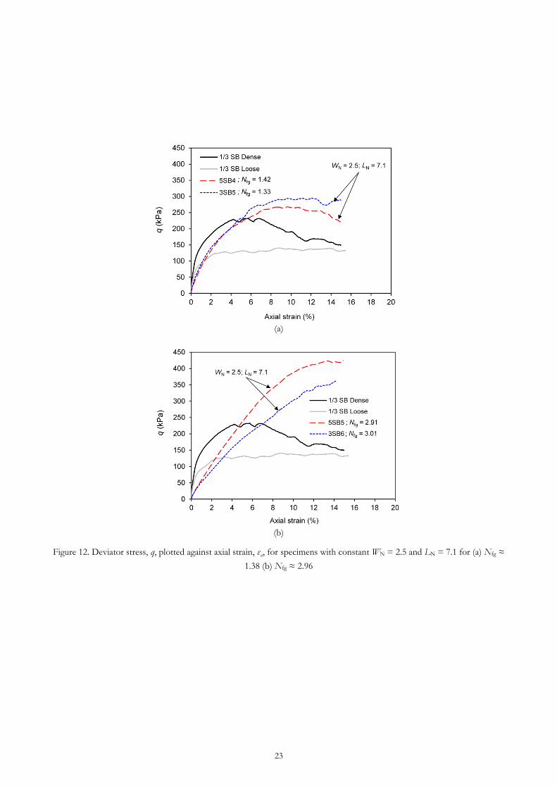
Figure 12 shows graphs of deviator stress against axial strain for reinforced specimens having similar LN and WN
and Nfg. In general, there appears to be correlation between the deviator stress and Nfg. The variation in deviator
stress is about 10 % in Figure 12a and 20 % in Figure 12b, for differences in Nfg of about 6% (Figure 12a) and 3%
(Figure 12b).
Conclusions
The mechanical properties of fibre reinforced large sized granular materials has been investigated with a particular
focus on the relative dimensions of the fibres and the grains and the fibre content, across different grain size
ranges. It has been shown that
1. The shear resistance of large grained materials such as scaled railway ballast can be improved by the
addition of appropriately sized fibre strips. For each material over the range of stresses considered, the
degree of improvement broadly increases with the normalised fibre length and width (LN and WN) and
the volumetric fibre ratio Vfr, subject to certain constraints.
2. The influence of the normalised fibre dimensions is strain dependent. At low strains (~0.1% ≤ εa ≤
1.0%), increasing the normalised fibre width, WN = Wf/D50 reduced the mobilised shear resistance
(deviator stress) of the mixture at a given strain. At larger strains, increasing the normalised fibre length
LN = Lf/D50 resulted in a higher mobilised shear resistance, provided that the fibres were wide enough to
ensure adequate fibre-grain contact.
3. When considering a particular granular material, the volumetric fibre ratio Vfr is an adequate measure of
the fibre content for interpreting the effect of the reinforcement on the stress-strain-strength behaviour
of the mixture. However, Vfr is not a suitable basis for comparing the behaviour of reinforced gravels
across different grain sizes. For strip fibres of constant thickness that remain thin relative to the grain
size, the effectiveness of the fibre reinforcements depends on the number of fibres available to interact
Page 13
10
with the grains. Hence the fibre content is better characterised by the numerical fibre:grain ratio Nfg,
defined as the ratio of the number of fibres Nf to the number of grains Ng.
4. For a full understanding of the effects of fibre reinforcement on scaled railway ballast, the effect of the
fibre tension that develops during shear in increasing the normal effective stress on the granular matrix,
and hence its resistance to shear stress, must be taken into account. When an appropriate correction is
made, the behaviour of the granular matrix in relation to the granular void ratio conforms with
conventional soil mechanics principles. Furthermore, almost complete agreement between the stress-
strain relationships across scales at a given numerical fibre to grain ratio Nfg, relative fibre width WN and
relative fibre length LN is obtained. This approach also gives insights into the development of fibre
tension as a function of Nfg, WN and LN.
Acknowledgements
This research was supported by the UK Engineering and Physical Sciences Research Council (EPSRC) through
the TRACK21 Programme Grant (EP/H044949). The first-named author further acknowledges the support of
the Faculty of Engineering and the Environment at the University of Southampton. All data supporting this study
are openly available from the University of Southampton repository.
Page 14
11
References
Abadi, T. (2015). Effect of Sleeper and Ballast Interventions on Performance. PhD. Thesis, University of Southampton.
Abadi, T., Le Pen, L., Zervos, A. & Powrie, W. (2016). Improving the performance of railway tracks through ballast
interventions. Proceedings of the Institution of Mechanical Engineers, Part F: Journal of Rail and Rapid Transit.
Aingaran, S. (2014). Experimental investigation of static and cyclic behaviour of scaled railway ballast and the effect of stress reversal. PhD.
Thesis, University of Southampton.
Ajayi, O., Le Pen, L. M., Zervos, A. & Powrie, W. (2016). A behavioural framework for fibre reinforced gravel. Geotechnique,
(Accepted).
Atkinson, J. H. (2000). Non-linear soil stiffness in routine design. Géotechnique, 50(5), 487-508.
Bathurst, R. J. & Raymond, G. P. (1987). Geogrid reinforcement of ballasted track. Transportation Research Record, 1153, 8-14.
Diambra, A., Ibraim, E., Russell, A. R. & Wood, D. M. (2013). Fibre reinforced sands: from experiments to modelling and
beyond. International Journal for Numerical and Analytical Methods in Geomechanics, 37(15), 2427-2455.
Diambra, A., Ibraim, E., Wood, D. M., Bennanni, Y. & Russell, A. R. (2008). Effect of sample preparation on the behaviour
of fibre reinforced sands. Proceedings of the 4th International Symposium on Deformation Characteristics of
Geomaterials, 2008 Atlanta. 629-636.
Diambra, A., Ibraim, E., Wood, D. M. & Russell, A. R. (2010). Fibre reinforced sands: Experiments and modelling. Geotextiles
and Geomembranes, 28(3), 238-250.
Dos Santos, A. P. S., Consoli, N. C. & Baudet, B. A. (2010). The mechanics of fibre-reinforced sand. Geotechnique, 60(10), 791-
799.
Heineck, K. S., Coop, M. R. & Consoli, N. C. (2005). Effect of microreinforcement of soils from very small to large shear
strains. Journal of Geotechnical and Geoenvironmental Engineering, ASCE, 131(8), 1024-1033.
Indraratna, B., Ngoc Trung, N. & Rujikiatkamjorn, C. (2011). Behavior of geogrid-reinforced ballast under various levels of
fouling. Geotextiles and Geomembranes, 29(3), 313-322.
Indraratna, B., Nimbalkar, S., Christie, D., Rujikiatkamjorn, C. & Vinod, J. (2010). Field Assessment of the Performance of a
Ballasted Rail Track with and without Geosynthetics. Journal of Geotechnical and Geoenvironmental Engineering, ASCE, 136(7),
907-917.
Ishikawa, T., Sekine, E. & Miura, S. (2011). Cyclic deformation of granular material subjected to moving-wheel loads.
Canadian Geotechnical Journal, 48(5), 691-703.
Jewell, R. A. & Wroth, C. P. (1987). Direct shear tests on reinforced sand. Geotechnique, 37(1), 53-68.
Koike, Y., Nakamura, T., Hayano, K. & Momoya, Y. (2014). Numerical method for evaluating the lateral resistance of
sleepers in ballasted tracks. Soils and Foundations, 54(3), 502-514.
Page 15
12
Le Pen, L., Bhandari, A. & Powrie, W. (2014). Sleeper End Resistance of Ballasted Railway Tracks. Journal of Geotechnical and
Geoenvironmental Engineering, ASCE, 140(5).
Le Pen, L., Powrie, W., Zervos, A., Ahmed, S. & Aingaran, S. (2013). Dependence of shape on particle size for a crushed rock
railway ballast. Granular Matter, 15(6), 849-861.
Lirer, S., Flora, A. & Consoli, N. C. (2011). On the strength of fibre-reinforced soils. Soils and Foundations, 51(4), 601-609.
Mcdowell, G. R., Harireche, O., Konietzky, H., Brown, S. F. & Thom, N. H. (2006). Discrete element modelling of geogrid-
reinforced aggregates. Proceedings of the Institution of Civil Engineers-Geotechnical Engineering, 159(1), 35-48.
Michalowski, R. L. (1997). Limit Stress for Granular Composites Reinforced with Continuous Filaments. Journal of Engineering
Mechanics, 123(8), 852-859.
Michalowski, R. L. & Cermak, J. (2002). Strength anisotropy of fiber-reinforced sand. Computers and Geotechnics, 29(4), 279-299.
Michalowski, R. L. & Cermak, J. (2003). Triaxial compression of sand reinforced with fibers. Journal of Geotechnical and
Geoenvironmental Engineering, ASCE, 129(2), 125-136.
Michalowski, R. L. & Zhao, A. G. (1996). Failure of fiber-reinforced granular soils. Journal of Geotechnical Engineering, ASCE,
122(3), 226-234.
Sadek, S., Najjar, S. S. & Freiha, F. (2010). Shear Strength of Fiber-Reinforced Sands. Journal of Geotechnical and Geoenvironmental
Engineering, 136(3), 490-499.
Sevi, A. & Ge, L. (2012). Cyclic Behaviors of Railroad Ballast within the Parallel Gradation Scaling Framework. Journal of
Materials in Civil Engineering, 24(7), 797-804.
Sevi, A. F. (2008). Physical modeling of railroad ballast using the parallel gradation scaling technique within the cyclical triaxial framework.
PhD Thesis, Missouri Univ. of Science and Technology, Rolla, MO.
Sevi, A. F., Ge, L. & Take, W. A. (2009). A Large-Scale Triaxial Apparatus for Prototype Railroad Ballast Testing. Geotechnical
Testing Journal, ASTM, 32(4), 297-304.
Page 17
14
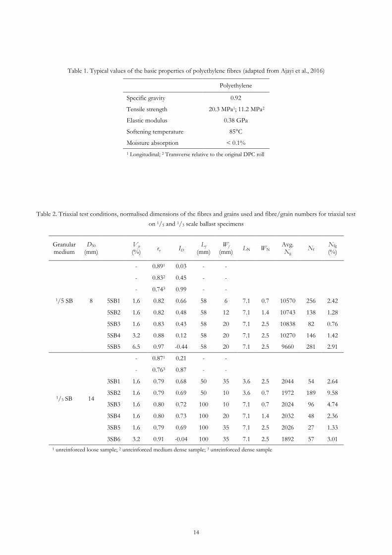
Table 1. Typical values of the basic properties of polyethylene fibres (adapted from Ajayi et al., 2016)
Polyethylene
Specific gravity 0.92
Tensile strength 20.3 MPa1; 11.2 MPa2
Elastic modulus 0.38 GPa
Softening temperature 85°C
Moisture absorption < 0.1%
1 Longitudinal; 2 Transverse relative to the original DPC roll
Table 2. Triaxial test conditions, normalised dimensions of the fibres and grains used and fibre/grain numbers for triaxial test
on 1/5 and 1/3 scale ballast specimens
Granular medium
D50 (mm)
Vfr (%)
eo ID Lf
(mm) Wf
(mm) LN WN
Avg. Ng
Nf Nfg (%)
1/5 SB 8
- 0.891 0.03 - -
- 0.832 0.45 - -
- 0.743 0.99 - -
5SB1 1.6 0.82 0.66 58 6 7.1 0.7 10570 256 2.42
5SB2 1.6 0.82 0.48 58 12 7.1 1.4 10743 138 1.28
5SB3 1.6 0.83 0.43 58 20 7.1 2.5 10838 82 0.76
5SB4 3.2 0.88 0.12 58 20 7.1 2.5 10270 146 1.42
5SB5 6.5 0.97 -0.44 58 20 7.1 2.5 9660 281 2.91
1/3 SB 14
- 0.871 0.21 - -
- 0.763 0.87 - -
3SB1 1.6 0.79 0.68 50 35 3.6 2.5 2044 54 2.64
3SB2 1.6 0.79 0.69 50 10 3.6 0.7 1972 189 9.58
3SB3 1.6 0.80 0.72 100 10 7.1 0.7 2024 96 4.74
3SB4 1.6 0.80 0.73 100 20 7.1 1.4 2032 48 2.36
3SB5 1.6 0.79 0.69 100 35 7.1 2.5 2026 27 1.33
3SB6 3.2 0.91 -0.04 100 35 7.1 2.5 1892 57 3.01
1 unreinforced loose sample; 2 unreinforced medium dense sample; 3 unreinforced dense sample
Page 19
16
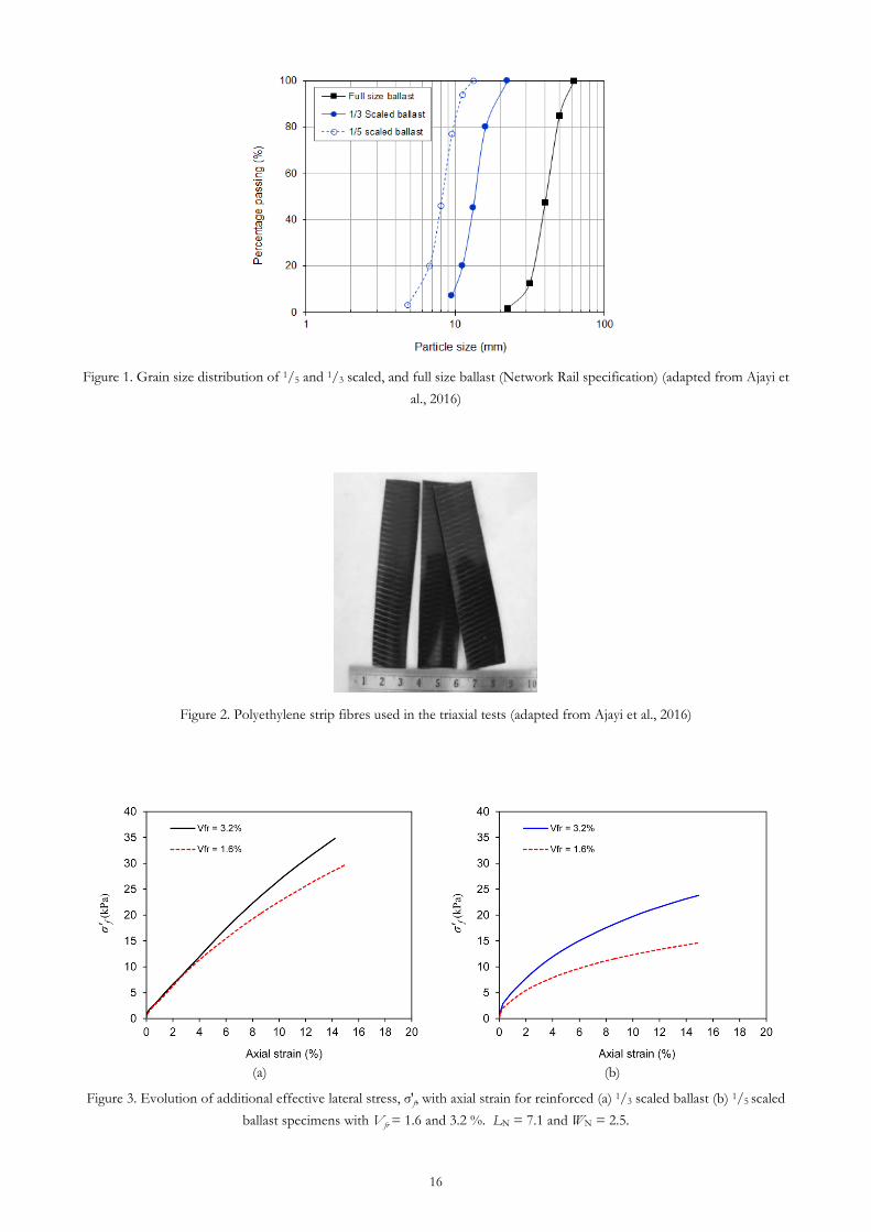
Figure 1. Grain size distribution of 1/5 and 1/3 scaled, and full size ballast (Network Rail specification) (adapted from Ajayi et
al., 2016)
Figure 2. Polyethylene strip fibres used in the triaxial tests (adapted from Ajayi et al., 2016)
(a)
(b)
Figure 3. Evolution of additional effective lateral stress, σ′f, with axial strain for reinforced (a) 1/3 scaled ballast (b) 1/5 scaled
ballast specimens with Vfr = 1.6 and 3.2 %. LN = 7.1 and WN = 2.5.
Page 20
17
Figure 4. Deviator stress q and volumetric strain vol against axial strain a for specimens of unreinforced 1/5 and 1/3 scaled
ballast. Cell pressure = 30 kPa
(a)
(b)
Figure 5. Evolution of additional effective confining stress, σ′f, with axial strain for reinforced 1/3 scaled ballast specimens
with Vfr =1.6 % for (a) varying WN while LN is constant (b) varying LN while WN is constant
Page 21
18
(a)
(b)
Figure 6. Effects of varying WN on the deviator stress, q, of fibre reinforced scaled ballast having Vfr = 1.6% and LN = 7.1 (a)
1/3 scaled ballast (b) 1/5 scaled ballast
Page 22
19
(a)
(b)
Figure 7. Effects of varying LN on the deviator stress, q, of fibre reinforced 1/3 scaled ballast having Vfr = 1.6%: (a) WN = 2.5
(b) WN = 0.7
Page 23
20
(a)
(b)
Figure 8. Deviator stress q and volumetric strain vol against axial strain a for specimens of (a) 1/3 (b) 1/5 scaled ballast with Vfr
= 0, 1.6 and 3.2 %. LN = 7.1 and WN = 2.5. Cell pressure = 30 kPa
Figure 9. Variation of Nfg with increasing Vfr for 1/3 and 1/5 scaled ballast
Page 24
21
(a)
(b)
Figure 10. Stress ratio (η) and volumetric strain (vol) of reinforced 1/3 and 1/5 scaled ballast specimens at constant LN = 7.1,
WN = 2.5 for (a) Nfg ≈ 3 (b) Nfg ≈ 1.3
Page 25
22
(a)
(b)
Figure 11. Corrected stress ratio (η″) and volumetric strain (vol) of reinforced 1/3 and 1/5 scaled ballast specimens at constant
LN = 7.1, WN = 2.5 for (a) Nfg ≈ 3 (b) Nfg ≈ 1.3
Page 26
23
(a)
(b)
Figure 12. Deviator stress, q, plotted against axial strain, εa, for specimens with constant WN = 2.5 and LN = 7.1 for (a) Nfg ≈
1.38 (b) Nfg ≈ 2.96