OM-'320 032383 OPERATION AND MAINTENANCE MANUAL for STEP-DOWN DISTRIBUTION TRANSFORMER PACKAGE PART NUMBER 486716 HOBART BROTHERS COMPANY POWER SYSTEMS DIVISION TROY, OHIO 45373 U.S.A. , i-.-----_..---- _.___ - .- ..- . ~~~ . ._..
Transcript
OM-'320 032383
OPERATION AND MAINTENANCE MANUAL
for
STEP-DOWN DISTRIBUTION TRANSFORMER PACKAGE
PART NUMBER 486716
HOBART BROTHERS COMPANY POWER SYSTEMS DIVISION
TROY, OHIO 45373 U.S.A.
,
i-.-----_..---- _.___ - .- ..- . ~~~ . ._ . .
SAFETY INSTRUCTIONS AND WARNINGS FOR ELECTRICAL POWER EQUIPMENT
ELECTRIC SHOCK can kill. Do not touch live electrical parts.
FUMES <AND GASES can be fire and health hazards. Ventilate all fumes and exhaust gases to the outside.
ELECTRIC ARC FLASH can injure eyes, burn skin, cause equipment damage, and ignite combustible material. Do not use power cables to break load and be sure tools don’t cause short circuits.
IMPROPER PHASE CONNECTION, PARALLELING, OR USE can damage this and attached equipment.
MOVING PARTS can cause serious injury. Keep clear of moving parts.
IMPORTANT - Protect yourself and others. Read and understand all the instructions in this Operating/Instruction Manual before installing, operating, or servicing this equipment. Keep this manual available for future
use by all operators.
A. GENERAL Equipment that supplies electrical power can cause serious injury or death, or damage to other equipment or
property, if the operator does not strictly observe all safety rules and take precautionary actions. Safe practices
have developed from past experience in the use of power source equipment. Certain of the practices below apply to
engine driven equipment.
B. SHOCK PREVENTION Bare conductors, or terminals in the output circuit, or ungrounded, electrically-live equipment can fatally shock a
person. Have a competent electrician verify that the equipment is adequately grounded and learn what terminals and parts are electrically HOT. Use proper safety clothing, procedures, and test equipment.
The electrical resistance of the body is decreased when wet, thus more easily permitting dangerous currents to flow
through it. When inspecting or servicing equipment, do not work in damp areas without being extremely careful.
Stand on dry rubber mat or dry wood, use insulating gloves that are effective when dampness or sweat cannot be
avoided. Keep your clothing dry and never work alone.
1. Installation and Grounding of Electrically Powered Equipment - Electrical equipment must be installed and maintained in accordance with the National Electrical Code, ANSI/NFPA 70, and other applicable codes.
A power disconnect switch or circuit breaker must be located at the equipment. Check the nameplate for voltage, frequency, and phase requirements. If only 3-phase power is available, connect any single-phase rated equipment to
only two wires of the 3-phase line. DO NOT CONNECT the equipment grounding conductor (lead) to the third live wire of the 3-phase line, as this makes the equipment frame electrically -- HOT, which can cause a fatal shock - ---*
Be sure to connect the grounding lead, if supplied in a power line cable, to the grounded switch box or building ground. If not provided, use a separate grounding lead. Be certain that the current (amperage) capacity of the
grounding lead will be adequate for the worst fault current situation. Refer to the National Electrical Code ANSI/
N FPA 70 for details. Do not remove plug ground prongs. Use correct mating receptacles.
2. Output Cables and Terminals - Inspect cables often for damage to the insulation and the connectors. Replace
or repair cracked or worn cables immediately. Do not overload cables. Do not touch output terminal while equip-
ment is energized.
Instruction 910082
Nov 16182 Revised
Page 1
C.
D.
E.
F.
G.
3. Service and Maintenance - This equipment must be maintained in good electrical and mechanical condition
to avoid hazards stemming from disrepair. Report any equipment defect or safety hazard to your supervisor and discontinue use of the equipment until its safety has been assured. Repairs should be made by qualified personnel
only. Shut OFF all power at the disconnecting switch or line breaker before inspecting or servicing the equipment. Lock switch OPEN (or remove line fuses) so that power cannot be turned ON accidentally. Disconnect power to
equipment if it is out of service. If troubleshooting must be done with the unit energized, have present another per- son trained in turning off the equipment anld’providing or calling for first aid.
FIRE AND EXPLbSlON PREVENTION
Fire and explosion are caused by electrical short circuits, combustible material near engine exhaust piping, misuse
of batteries and fuel, or unsafe operating or fueling conditions.
1. Electrical Short Circuits and Overloads - Overloaded or shorted equipment can become hot enough to cause fires either by self destruction or causing nearby combustibles to ignite. Provide primary input protection to re-
move short circuited or heavily overloaded equipment from the line.
2. Battery - Batteries may explode and/or give off flammable hydrogen gas. The acid and arcing from a ruptured
battery can cause fires and additional failures. When servicing, do not smoke, causing sparking, or use open flame
near the battery.
3. Enaine Fuel - Use only approved fuel container or fueling system. Fires and explosions can occur if the fuel
tank is not grounded prior to and during fuel transfer. Shut unit DOWN before removing fuel tank cap. Do not
completely fill tank. Heat from the equipment may cause fuel expansion overflow. Remove all spilled fuel im- mediately including any that penetrates the unit. After cleanup, open equipment doors and blow fumes away with compressed air.
TOXIC FUME PREVENTION
Carbon Monoxide - Engine exhaust fumes can kill and cause health problems. Pipe or vent the exhaust fumes to a
suitable exhaust duct or outdoors. Never locate engine exhausts near intake ducts or air conditioners.
BODILY INJURY PREVENTION Serious injury can result from contact with fans, belts, and pulleys inside the equipment. Shut DOWN equipment for inspection and routine maintenance. When equipment is in operation use extreme care in doing necessary
troubleshooting and adjustment.
MEDICAL AND FIRST AID TREATMENT
First aid facilities and a qualified first aid person should be available for each shift for immediate treatment of all
injury victims. Electric shock victims should be checked by a physician and taken to a hospital immediately if any
abnormal signs are observed.
EMERGENCY FIRST AID
Call physician immediately. Seek additional assistance and use First Aid techniques recommended
by American Red Cross until medical help arrives.
IF BREATHING IS DIFFICULT, give oxygen, if available, and have victim lie down. FOR ELEC- TRlCAL SHOCK, turn off power. Remove victim; if not breathing, begin artificial respiration, preferably mouth-to-mouth. If no detectable pulse, begin external heart massage. Call Emergency
Rescue Squad immediately.
EQUIPMENT PRECAUTIONARY LABELS
Inspect all precautionary labels on the equipment monthly. Order and replace all labels that cannot be easily read.
Page 2 Instruction 910082
Revised Nov 16182
, OM-320
INTRODUCTION
This rilanual contains opera 4 ibn and maintenance information for a Step-Down Distributjon Transformer Package manufactured by Hobart Brothers Company, Power Systems Division, Troy, Ohio 45373.
The'manual is not intended to be a textbook on electricity or electronics. Its primary purpose is to provide information and instructions to experienced operators, electricians, and mechanics who have never seen or operated this equipment. It is the intent of the manual to guide and assist operators and maintenance people in the proper use and care of the equipment.
Use of the manual should not be put off until a trouble or need for help de- velops. Read the instructions before starting the unit. Learn to use the manual and to locate information contained in it. Its style and arrangement are very similar to commercial aircraft manuals. Each new section starts with Page 1. Each page is identified by chapter, section, and page number in the lower, outside corner. When information located in another portion of the manual is referred to, its location is identified by chapter, section, and paragraph, or figure number. For example, (see 2-3, Para. 4) refers to infor- mation located in Chapter 2, Section 3, paragraph 4. If a chapter and section are not indicated in a reference, the referenced material is located in the same section as the reference, Example, (See Para. 3).
In addition to operation and maintenance instructions, the manual contains an illustrated parts list in Chapter 4.
Content of the manual is arranged as follows:
Chapter 1. Description/Operation Chapter Chapter 2. Servicing Chapter 3. Troubleshooting Chapter 4. List of Manufacturer's Literature
If you have any questions concerning your Hobart Power Systems Division equip- ment, you are invited to contact our Service Department by mail, telephone or TWX.
Write: Hobart Brothers Company Power Systems Division Service Department Troy, Ohio 45373 U.S.A.
Call: Area Code (513) 339-6000 Extension 4276
TWX: 810-456-2907
Mar 23183 Int reduction
Page l/2
._ ,’ w 1
TABLE OF CONTENTS
SUBJECT
Introduction
Description/Operation i '!
,Description
1. General
2. Identification
3. System Description
4. Detailed Description
A. Vacuum Contactor and Control Panel Assembly
B. Transformer (Part No. 82C-1054)
c. Canopy
D. Overload Current Panel Assembly (Part No. 487099)
Preparation for Use
1. Installation
A. Receipt of Equipment
B. Mounting
c. Power Connections
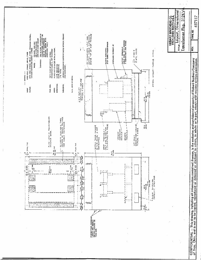
D. Output Connections (Refer to Drawing 487117)
Operation
1. General
Service
Maintenance and Inspection
1. General
2. Lubrication
3. Parts Replacement
. .- - _ - -..-. -. 4Y Inspection Check List
Mar 23/83 .- -. ,----. _. ~ .__
OM-320
CHAPTER/SECTION PAGE
112
1-o 1
l-l 1
4
1-2 112
112
l/2
l/2
112
112
1-3 l/2
l/2
2-o l/2
2-l ,1/z
112
l/2
l/2
l/2 Contents
Page 1
OM-320
._ / / _, __ -~ I 1 TABLE OF CONTENTS (CONTINUED)
SUBJECT CHAPTER/SECTION PAGE
Troubleshooting 3-l l/2
Manufacturer's Literature Includk/' 4-o l/2
Contents .- . . .~ .---- _ .- . Mar 23/83
i?a.ge-2-.._.
1.
i.
3.
_ - - - ._.-- -
CHAPTER 1. DESCRIPTION/OPERATION
SECTION 1. DESCRIPTION
General
The step-down distribut&transformer package covered by this manual is ( manufactured by Hobart Brothers Company, Power Systems Division, Troy, Ohio ,45373 U.S.A. Specifications are listed in Fig. 2.
The purpose of the unit is to control and decrease the 4160 Volts AC, 460 I
Hz, 3 Phase power from a comparatively remote location to the 575 Volt,,400 Hz, 3 Phase power required by the Distribution Gate Boxes used in this
1
system.
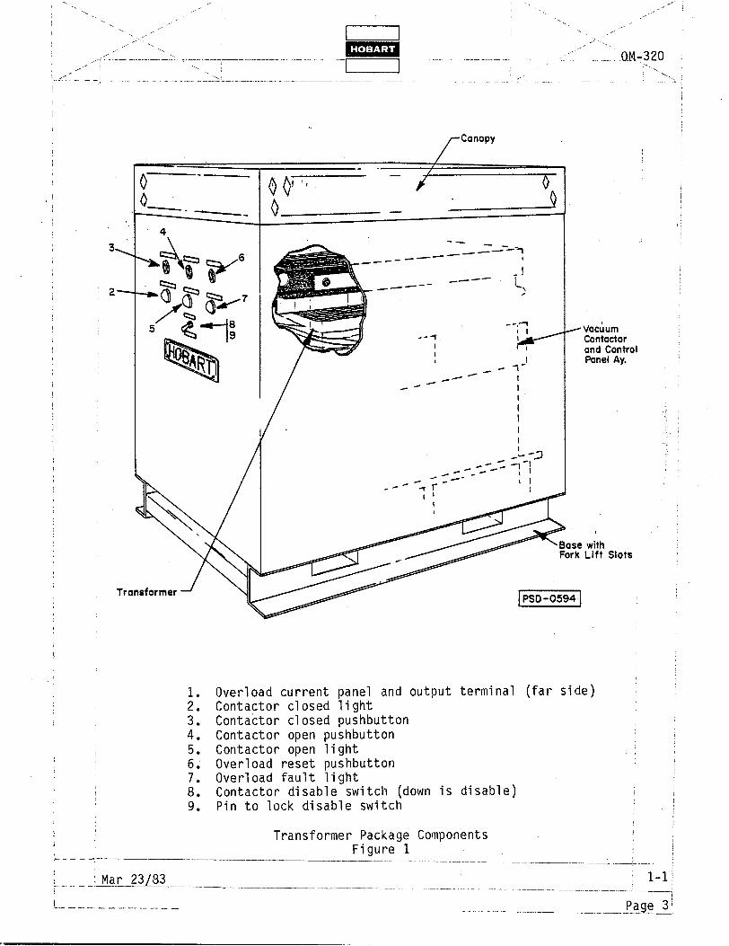
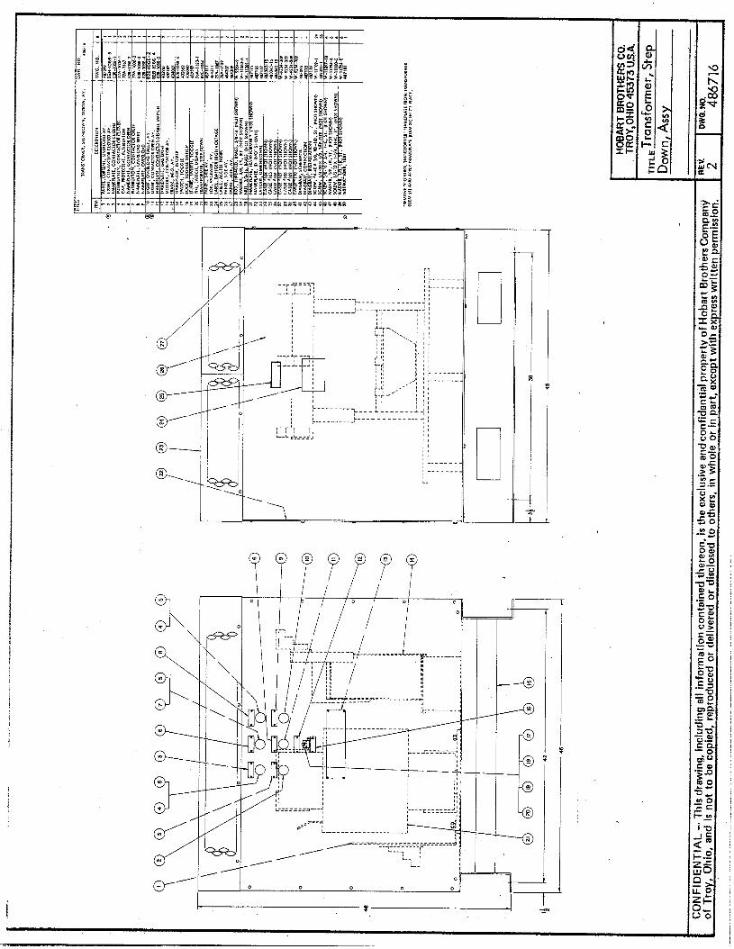
Refer to Fig. 1; A sheet metal cabinet houses the transformer, input vac- uum contactor and control assembly, controls and lights on the front panel, secondary overload panel assembly with output terminals, and the associated 1 cables, labels, and bus bars.
Identification
The step-down distribution transformer package is identified by Hobart Part ~ Number 486716. Consult your sales order for other components of your Power Delivery System.
System Description
The Hobart 312 kVA Step-down Transformer Package 486716 is used as part of a 400 Hz power delivery system for aircraft ground power which utilizes high voltage transmission of three phase, 400 Hz power. This system allows more power to be sent longer distances more economically. Typically, the total system consists of:
A. A 400 Hz generator powered by an electric motor powered from an elec- tric utility.
B. A step-up transformer package with suitable controls and transformer to : step up the 400 Hz, 3 phase generated voltage to 4160 volts.
c. A step-down transformer package with suitable controls and transformer to reduce (step-down) the 4160 volt, 3 phase, 400 Hz power to the 575
;
volt, 3 phase, 400 Hz required by the distribution network of gate boxes used here.
D. Distribution Gate Boxes (usually a network of many) which receive ,the stepped down voltage and reduce it further to ZOO/115 volt, 3 phase:, 400 Hz (if not at that voltage) and provide output control and connection means to the load.
__ Mar 23/83 .._.~___._.__ l-l : I i----- -_ ---.- _.__. __ --- --~~ ---...-. p&J&J--:
I 1 m -I---
I I
,--
,_. ‘”
,,
-_
:- IOM-320:.:.
'4. Detailed Description
A. Vacuum Contactor and Control Panel Assembly
Refer to Drawing 487107 f& component location, identification, and part number. This assembly provides the high voltage vacuum contactor, the 4160 to 115 V control transformer, the memory and time delay board assembly, the 24 V DC control power supply, the contactor closed relay, the 4160 volt input terminal board with cable lugs, and the associated fuses, hardware, and associated parts.
The vacuum contactor is the interrupting and primary control means for the transformer package. The step-down control transformer provides 115 V AC to vacuum contactor operating coil and to the 24 V DC power, supply. The memory and time delay relay is powered by the 24 V DC pow- er supply and acts to remove vacuum contactor operating coil voltage if an output overload signal is received from the overload current panel assembly. The contactor disable switch and control fuse are provided to turn off the vacuum contactor operating circuit intentionally or whenever a fault exists in the operating circuit. Once the memory and time delay circuitry is tripped, the contactor is held open until the circuitry is reset by voltage removal such as from the reset switch.
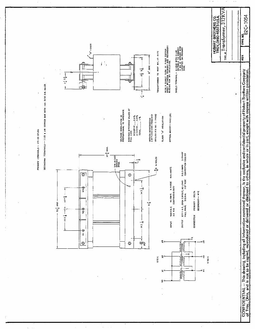
B. Transformer (Part No. 82C-1054)
The step-down power transformer is a 3 phase, air cooled unit with a delta connected primary (input) and a wye connected with neutral (4 wire) secondary. It also has a grounded copper RF1 shield between the primary and secondary windings to minimize interference problems. The transformer has class "H" insulation for added reserve margin and longer life. The bottom frame of the transformer has a 3/8-16 ground stud provided to facilitate grounding of the shield and other compo- nents. The high voltage transmission of power allows more power to be transmitted further with smaller cables.
c. Canopy
The unit is enclosed in a metal canopy consisting of a welded steel base and a welded steel frame with sheet metal side panels and top cover bolted in place. The canopy is designed to promote convection cooling of the transformer. The open construction of the base allows the intake of cooling air, which is circulated over the transformer and cabling, and expelled through openings existing in the top cover. Necessary switches and lights used in operating the transformer package are located on the front panel and identified in Fig. 1 and in the schematic and wiring diagrams as well as on drawing 486716.
___ --I__
Mar 23/83 /
- ~~. .-..-.. ----.-- ---_J
c- _- -
00‘ - ! ! ‘f b -
A Vacuum Contactor and Control Panel Ay.
with Lift Slots 8
1. Overload current panel and output terminal (far side) 2. Contactor closed light 3. Contactor closed pushbutton 4. Contactor open pushbutton 5. Contactor open light 6. Overload reset pushbutton 7. Overload fault light 8. Contact,or disable switch (down is disable) 9. Pin to lock disable switch
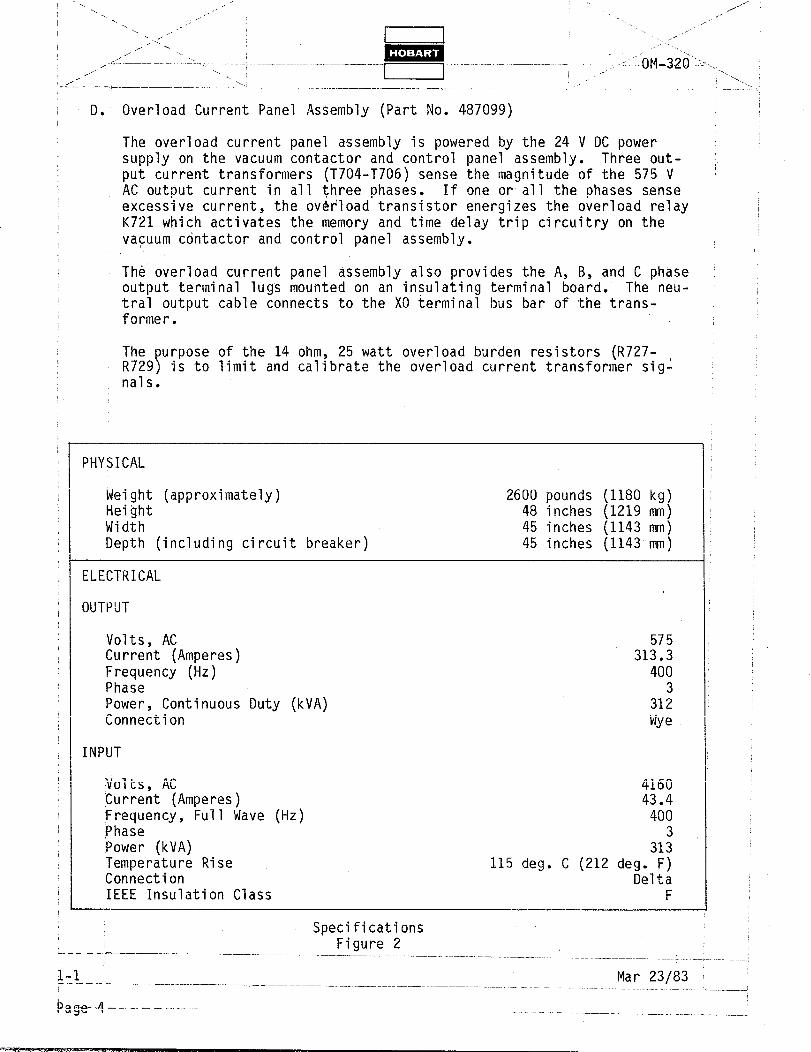
D. Overload Current Panel Assembly (Part No. 487099)
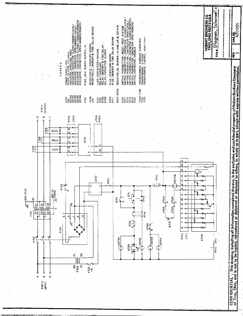
The overload current panel assembly is powered by the 24 V DC power supply on the vacuum contactor and control panel assembly. Three out- put current transformers (T704-T706) sense the magnitude of the 575 V AC output current in all three phases. If one or all the phases sense excessive current, the ov&load transistor energizes the overload relay K721 which activates the memory and time delay trip circuitry on the vacuum cdntactor and control panel assembly.
Th& overload current panel assembly also provides the A, B, and C phase output terminal lugs mounted on an in?ulating terminal board. The neu- tral output cable connects to the X0 terminal bus bar of the trans- former.
The R729 P
urpose of the 14 ohm, 25 watt overload burden resistors (R727- is to limit and calibrate the overload current transformer sig:
Volts, AC Current (Amperes) Frequency (Hz) Phase Power, Continuous Duty (kVA) Connection
INPUT
575 313.3
400 3
312 We
Volts, AC 4160 Current (Amperes) 43.4 Frequency, Full Wave (Hz) 400 Phase 3 Power (kVA) 313 Temperature Rise %onnection
115 deg. C (212 deg. F) Delta
IEEE Insulation Class F
Specifications Figure 2 --- --,
Mar 23/83 !
SECTION 2. PREPARATION FOR USE
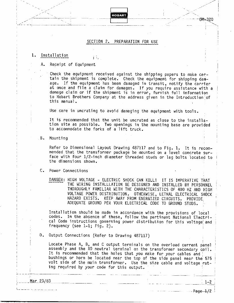
1. Installation i 1, A. Receipt of Equipment
Check the equipment received against the shipping papers to make cer- tain the shipment is complete. Check the equipment for shipping dam- age. If the equipment has been damaged in transit, notify the carrier : at once and file a claim for damages. If you require assistance with a ! damage claim or if the shipment is in error, furnish full information to Hobart Brothers Company at the address given in the Introduction of this manual.
Use care in uncrating to avoid damaging the equipment with tools.
It is recommended that the unit be uncrated as close to the installa- tion site as possible. Two openings in the mounting base are provided to accommodate the forks of a lift truck.
B. Mounting
Refer to Dimensional Layout Drawing 487117 and to Fig. 1. It is recom- mended that the transformer package be mounted on a level concrete sur- face with four l/2-inch diameter threaded studs or lag bolts located to the dimensions shown.
r -I. Power Connections .
DANGER: HIGH VOLTAGE - ELECTRIC SHOCK CAN KILL! IT IS IMPERATIVE THAT THE WIRING INSTALLLATION BE DESIGNED AND INSTALLED BY PERSONNEL THOROUGHLY FAMILIAR WITH THE CHARACTERISTICS OF 400 HZ AND HIGH : VOLTAGE POWER DISTRIBUTION. HAZARD EXI STS.
ADEQUATE GROUND PER YOUR ELECTRICAL CODE TO GROUND STUDS. /
Installation should be made in accordance with the provisions of local j codes. In the absence of these, follow the pertinent National Electri- cal Code instructions governing power distribution for this voltage: and frequency (see l-l; Fig. 2).
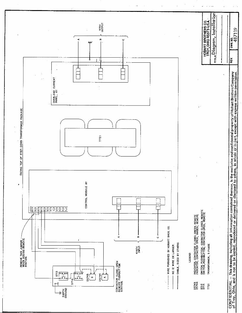
D. Output Connections (Refe,r to Drawing 487117)
Locate Phase A, B, and C output terminals on the overload current pianel assembly and the X0 neutral terminal on the transformer secondary coil. It is recommended that the holes that you make for your cables and I bushings or horn be located near the top of the side panel near the 575 volt side of the main transformer.
i Use the size cable and voltage rat- '
ing required by your code for this output.
_ - - .- ->--.--..
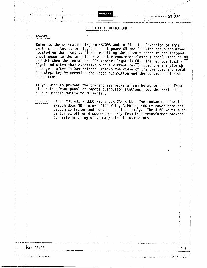
SECTION 3. OPERATION I
1. General
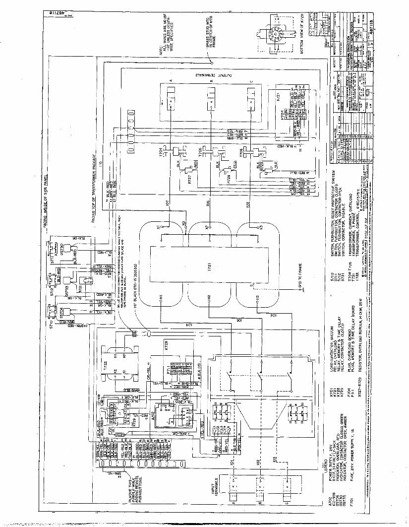
Refer to the schematic diagram 487095 and to Fig. 1. Operation of this j unit is limited to turning the input power ON and OFF with the pushbuttons located on the front pa&land resetting thycircurafter it has tripped.
~
Input power to the unit is ON when the contactor closed (Green) light is fl and OFF when the contactor TEN (amber) light is ON. The red overload
:
lig,hmndicates that excessive output current hastripped the transformer package. After it has tripped, remove the cause of the overload and reset the circuitry by pressing the reset pushbutton and the contactor closed pushbutton.
If you wish to prevent the transformer package from being turned on from either the front panel or remote pushbutton stations, set the S721,Con- i tactor Disable switch to "Disable".
DANGER: HIGH VOLTAGE - ELECTRIC SHOCK CAN KILL! The contactor disable switch does NOT remove 4160 Volt, 3 Phase, 400 Hz Power from the vacuum contazr and control panel assembly. The 4160 Volts must be turned off or disconnected away from this transformer package for safe handling of primary circuit components.
.., ,’ . _, 1 .
N. ,i ”
-. .- .’ . . _,
1 ,>-_ ,, “. .,’ -x.
/ -..
. ,, ’ ,,’
! .A ^- ._ - _- ;--
1.
2.
3.
4.
lmd .I. - - .- -.
-._ .
DM.-320...._:;:--::,
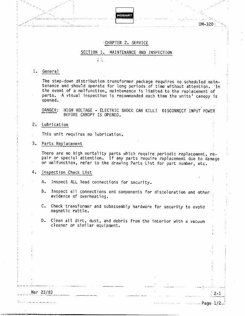
,.CHAPTER 2. SERVICE
SECTION 1. MAINTENANCE AND INSPECTION
i 1,
General
The step-down distribution transformer package requires no scheduled main- tenance and should operate for long periods of time without attention. In the event of a malfunction, maintenance is limited to the replacement of parts. opened.
A visual inspection is recommended each time the units' canopy is
DANGER: HIGH VOLTAGE - ELECTRIC SHOCK CAN KILL! DISCONNECT INPUT POWER BEFORE CANOPY IS OPENED.
Lubrication
This unit requires no lubrication.
Parts Replacement
There are no high mortality parts which require periodic replacement, re- pair or special attention. or malfunction,
If any parts require replacement due to damage refer to the drawing Parts List for part number, etc.
Inspection Check List
A. Inspect ALL lead connections for security.
B. Inspect all connections and components for discoloration and other evidence of overheating.
C. Check transformer and subassembly hardware for security to avoid magnetic rattle.
D. Clean all dirt, dust, and debris from the interior with a vacuum cleaner or similar equipment.
._
CHAPTER 3. TROUBLESHOOTING
There are no troubleshooting procedures feasible for this unit. test procedures are detailed in Chapter 2, Section 1.
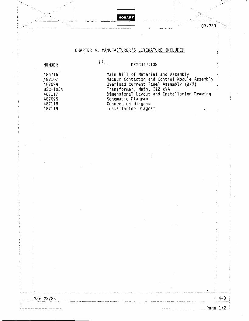
Main Bill of Material and Assembly Vacuum Contactor and Control Module Assembly Overload Current Panel Assembly (B/M) Transformer, Main, 312 kVA Dimensional Layout and Installation Drawing Schematic Diagram Connection Diagram Installation Diagram