24
917.375940 Owner’s Manual 532 19 65-29 01.21.05 BY Printed in U.S.A.

917.375940Owner’s Manual
532 19 65-29 01.21.05 BY Printed in U.S.A.

2
WARNING: Battery posts, terminals and related ac ces so ries contain lead and lead compounds, chemicals known to the State of Cal i for nia to cause can cer and birth defects or oth er re pro duc tive harm. Wash hands after handling.
WARNING: Engine exhaust, some of its con stit u ents, and certain vehicle com po -nents contain or emit chem i cals known to the State of Cal i for nia to cause can cer and birth defects or oth er re pro duc tive harm.
CAUTION: Always disconnect spark plug wire and place wire where it cannot contact spark plug in order to prevent ac ci den tal starting when setting up, trans port ing, adjusting or making re pairs.
Look for this symbol to point out im- por tant safety precautions. It meansCAUTION!!! BE COME ALERT!!! YOUR SAFE TY IS IN VOLVED.
CAUTION: Muffl er and other engine parts become extremely hot during operation and remain hot after engine has stopped. To avoid severe burns on contact, stay away from these areas.
Safe Operation Practices for Walk-Behind MowersIMPORTANT: THIS CUTTING MACHINE IS CAPABLE OF AMPUTATING HANDS AND FEET AND THROW ING OBJECTS. FAILURE TO OBSERVE THE FOLLOWING SAFETY INSTRUCTIONS COULD RESULT IN SERIOUS INJURY OR DEATH.
SAFETY RULES
I. GENERAL OPERATION• Read, understand, and follow all instructions on the
machine and in the manual(s) before starting. Be thor- ough ly familiar with the controls and the proper use of the machine before starting.
• Do not put hands or feet near or under rotating parts. Keep clear of the discharge opening at all times.
• Only allow responsible individuals, who are familiar with the instructions, to operate the machine.
• Clear the area of objects such as rocks, toys, wire, bones, sticks, etc., which could be picked up and thrown by the blade.
• Be sure the area is clear of other people before mow- ing. Stop machine if anyone enters the area.
• Do not operate the mower when barefoot or wearing open sandals. Always wear substantial foot wear.
• Do not pull mower backwards unless absolutely nec- es sary. Always look down and behind before and while moving backwards.
• Never direct discharged material toward anyone. Avoid discharging material against a wall or obstruc-tion. Material may richochet back toward the operator. Stop the blade when crossing gravel surfaces.
• Do not operate the mower without proper guards, plates, grass catcher or other safety protective devices in place.
• See manufacturer’s instructions for proper operation and installation of accessories. Only use accessories approved by the manufacturer.
• Stop the blade(s) when crossing gravel drives, walks, or roads.
• Stop the engine (motor) whenever you leave the equip- ment, before cleaning the mower or unclogging the chute.
• Shut the engine (motor) off and wait until the blade comes to complete stop before removing grass catch er.
• Mow only in daylight or good artifi cial light.• Do not operate the machine while under the infl uence
of alcohol or drugs.• Never operate machine in wet grass. Always be sure of
your footing: keep a fi rm hold on the handle and walk; never run.
• Disengage the self-propelled mechanism or drive clutch on mowers so equipped before starting the engine (motor).
• If the equipment should start to vibrate abnormally, stop the engine (motor) and check immediately for the cause. Vibration is generally a warning of trouble.
• Always wear safety goggles or safety glasses with side shields when operating mower.
II. SLOPE OPERATIONSlopes are a major factor related to slip and fall accidents which can result in severe injury. All slopes require extra caution. If you feel uneasy on a slope, do not mow it.DO:• Mow across the face of slopes: never up and down. Exer-
cise extreme caution when changing direction on slopes.• Remove obstacles such as rocks, tree limbs, etc.• Watch for holes, ruts, or bumps. Tall grass can hide
obstacles.DO NOT:• Do not trim near drop-offs, ditches or embankments.
The operator could lose footing or balance.• Do not trim excessively steep slopes.• Do not mow on wet grass. Reduced footing could cause
slipping.
III. CHILDRENTragic accidents can occur if the operator is not alert to the presence of children. Children are often attracted to the machine and the mowing activity. Never assume that children will remain where you last saw them.• Keep children out of the trimming area and under the
watchful care of another re spon si ble adult.• Be alert and turn machine off if children enter the
area.• Before and while walking backwards, look behind and
down for small children. • Never allow children to operate the machine.• Use extra care when approaching blind corners, shrubs,
trees, or other objects that may obscure vision.
IV. SAFE HANDLING OF GASOLINEUse extreme care in handling gasoline. Gasoline is ex-tremely fl ammable and the vapors are explosive.• Extinguish all cigarettes, cigars, pipes and other sources
of ignition.• Use only an approved container.• Never remove gas cap or add fuel with the engine run-
ning. Allow engine to cool before refueling.
3
CONGRATULATIONS on your purchase of a new lawn mower. It has been designed, engineered and man u fac tured to give you the best possible dependability and performance.
Should you experience any problem you cannot easily remedy, please contact your nearest authorized service center/department. We have competent, well-trained tech ni cians and the proper tools to service or repair this lawn mower.
Please read and retain this manual. The instructions will enable you to assemble and maintain your lawn mower properly. Always observe the “SAFETY RULES”.
SERIAL NUMBER: _________________________________
DATE OF PURCHASE: _______________________
THE MODEL AND SERIAL NUMBERS WILL BE FOUND ON A DECAL ATTACHED TO THE REAR OF THE LAWN MOWER HOUSING.
YOU SHOULD RECORD BOTH SERIAL NUMBER AND DATE OF PURCHASE AND KEEP IN A SAFE PLACE FOR FUTURE REFERENCE.
CUSTOMER RESPONSIBILITIES• Read and observe the safety rules.• Follow a regular schedule in maintaining, caring for and
using your lawn mower.• Follow the instructions under “Maintenance” and “Stor-
age” sec tions of this own er’s manual.
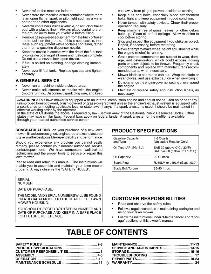
TABLE OF CONTENTSSAFETY RULES ......................................................... 2-3PRODUCT SPECIFICATIONS....................................... 3CUSTOMER RESPONSIBILITIES................................. 3ASSEMBLY.................................................................4-5OPERATION ............................................................. 6-10MAINTENANCE SCHEDULE ...................................... 11
MAINTENANCE...................................................... 11-13SERVICE AND AD JUST MENTS ............................ 14-15STORAGE ............................................................... 15-16TROU BLE SHOOT ING ................................................. 17REPAIR PARTS....................................................... 18-23WARRANTY................................................................. 24
• Never refuel the machine indoors.• Never store the machine or fuel container where there
is an open fl ame, spark or pilot light such as a water heater or on other appliances.
• Never fi ll containers inside a vehicle, on a truck or trailer bed with a plastic liner. Always place containers on the ground away from your vehicle before fi lling.
• Remove gas-powered equipment from the truck or trailer and refuel it on the ground. If this is not possible, then refuel such equipment with a portable container, rather than from a gasoline dispenser nozzle.
• Keep the nozzle in contact with the rim of the fuel tank or container opening at all times until fueling is complete. Do not use a nozzle lock-open device.
• If fuel is spilled on clothing, change clothing immedi-ately.
• Never overfi ll fuel tank. Replace gas cap and tighten securely.
V. GENERAL SERVICE• Never run a machine inside a closed area.• Never make adjustments or repairs with the engine
(motor) running. Disconnect spark plug wire, and keep
wire away from plug to prevent accidental starting.• Keep nuts and bolts, especially blade attachement
bolts, tight and keep equipment in good condition.• Never tamper with safety devices. Check their proper
operation regularly.• Keep machine free of grass, leaves, or other debris
build-up. Clean oil or fuel spillage. Allow machine to cool before storing.
• Stop and inspect the equipment if you strike an object. Repair, if necessary, before restarting.
• Never attempt to make wheel height adjustments while the engine (motor) is running.
• Grass catcher components are subject to wear, dam- age, and deterioration, which could expose moving parts or allow objects to be thrown. Frequently check com po nents and replace with manufacturer’s rec om -mend ed parts, when necessary.
• Mower blade is sharp and can cut. Wrap the blade or wear gloves, and use extra caution when servicing it.
• Do not change the engine governor setting or overspeed the engine.
• Maintain or replace safety and instruction labels, as necessary.
WARNING: This lawn mower is equipped with an internal com bus tion engine and should not be used on or near any un im proved forest-covered, brush-covered or grass-cov ered land unless the engine’s exhaust system is equipped with a spark arrester meeting applicable local or state laws (if any). If a spark arrester is used, it should be maintained in effective working order by the operator.In the state of California the above is required by law (Section 4442 of the California Public Resources Code). Other states may have similar laws. Federal laws apply on federal lands. A spark arrester for the muffl er is available through your nearest authorized service center.
PRODUCT SPECIFICATIONSGasoline Capacity 1.6 Quartsand Type: (Unleaded Regular Only)
Oil Type (API SG–SL): SAE 30 (above 0°C / 32°F) SAE 5W-30 (below 0°C / 32°F)
Oil Capacity: 20 Ounces
Spark Plug: RJ19LM or J19LM (Gap: .030")
Blade Bolt Torque: 35-40 ft. lbs.

4
ASSEMBLYRead these instructions and this man u al in its entirety before you attempt to assemble or operate your new lawn mow er.
IMPORTANT: THIS LAWN MOWER IS SHIPPED WITH- OUT OIL OR GASOLINE IN THE ENGINE.
Your new lawn mower has been as sem bled at the factory with the ex cep tion of those parts left unassembled for ship-ping purposes. All parts such as nuts, washers, bolts, etc., necessary to com plete the as sem bly have been placed in the parts bag. To ensure safe and proper operation of your lawn mow er, all parts and hard ware you assemble must be tightened se cure ly. Use the correct tools as nec es sary to ensure proper tightness.
TO RE MOVE LAWN MOW ER FROM CAR TON1. Remove loose parts included with mower.2. Cut down two end corners of car ton and lay end panel
down fl at.3. Remove all packing materials ex cept padding be tween
upper and lower handle and padding holding operator presence control bar to up per handle.
4. Roll lawn mower out of carton and check carton thor-ougly for ad di tion al loose parts.
HOW TO SET UP YOUR LAWN MOW ER TO UNFOLD HANDLE (See Figs. 1 and 2)IMPORTANT: UNFOLD HANDLE CAREFULLY SO AS NOT TO PINCH OR DAMAGE CON TROL CABLES. 1. Raise lower handle to operating position and align hole
in handle with one of the height positioning holes in the handle bracket.
2. Insert handle bolt through handle and bracket and secure with knob.
3. Repeat for opposite side of handle.4. Remove protective padding, raise upper handle sec-
tion into place on lower handle and tighten both handle knobs.
5. Remove packing material from around control bar.
Your handles may be adjusted for your mowing comfort. Refer to “ADJUST HANDLE” in the Service and Ad just ments sec tion of this man u al.
FIG. 2
HANDLE BRACKET
KNOB
BOLT
FIG. 1
OPERATOR PRESENCECONTROL BAR
HANDLE KNOB
LIFT UP
LIFT UP
LOWER HANDLE
MOWING PO SI TION
UPPER HANDLE
5
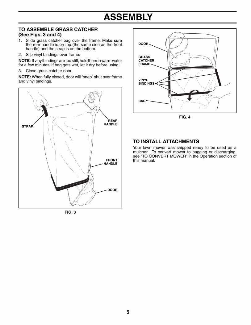
TO ASSEMBLE GRASS CATCHER(See Figs. 3 and 4)1. Slide grass catcher bag over the frame. Make sure
the rear handle is on top (the same side as the front handle) and the strap is on the bottom.
2. Slip vinyl bindings over frame.
NOTE: If vinyl bindings are too stiff, hold them in warm water for a few minutes. If bag gets wet, let it dry before using.3. Close grass catcher door.
NOTE: When fully closed, door will “snap” shut over frame and vinyl bindings.
TO INSTALL ATTACHMENTSYour lawn mower was shipped ready to be used as a mulcher. To convert mower to bagging or discharging, see “TO CON VERT MOWER” in the Operation section of this man u al.
GRASS CATCHER FRAME
FIG. 4
VINYLBINDINGS
DOOR
BAG
ASSEMBLY
FIG. 3
FRONT HANDLE
REAR HANDLE
STRAP
DOOR

6
KNOW YOUR LAWN MOWERREAD THIS OWNER'S MANUAL AND SAFETY RULES BEFORE OPERATING YOUR LAWN MOWER. Compare the illustrations with your lawn mower to familiarize yourself with the location of various controls and adjustments. Save this manual for future reference.
MEETS CPSC SAFETY REQUIREMENTSOur rotary walk-behind power lawn mowers conform to the safety standards of the American National Standards Institute and the U.S. Consumer Product Safety Commission. The blade turns when the engine is running.
OPERATOR PRESENCE CONTROL BAR – must be held down to the handle to start engine. Release to stop engine.
MULCHER DOOR – allows conversion to discharge or bagging operation.
STARTER HANDLE – used for starting the engine.
HOUSING
GRASS CATCHER
DRIVE CONTROL LEVER – used to engage power-pro-pelled forward motion lawn mower.
DUAL POINT HEIGHT ADJUSTER – used to adjust cutting height of lawn mower.
PRIMER – pumps additional fuel from the carburetor to the cylinder for use when starting a cold engine.
OPERATOR PRESENCE CON TROL BAR
STARTER HANDLE
EN GINE OIL CAP WITH DIPSTICK
HANDLE KNOB
GAS O LINE FILL ER CAP
These symbols may appear on your lawn mower or in literature supplied with the product. Learn and understand their meaning.
MULCHER DOOR
OPERATION
IMPORTANT: This lawn mower is shipped WITHOUT OIL OR GASOLINE in the engine.
PRIMER
DRIVE CONTROL LEVER
DRIVE COVER
MUFFLER
DUAL POINT HEIGHT ADJUSTER LEVER
AIR FILTER SPARK PLUG

7
2. Turn nut on underside of drive control to increase drive speed.
3. Operate mower to test drive speed. Readjust as required.4. If condition fails to improve after the above steps (for-
ward speed remains the same), your drive belt is worn and should be re placed.
TO ADJUST CUTTING HEIGHT (See Fig. 6)Both front wheels are adjusted by a single lever on the left front wheel. Likewise, both rear wheels are adjusted by a single lever on the left rear wheel.• Pull adjuster lever toward wheel. To raise mower, move
lever forward to desired position. To lower mow er, move the lever toward the rear.
Be sure to adjust both front and rear wheels to same height.
HOW TO USE YOUR LAWN MOWERENGINE SPEED The engine speed was set at the factory for optimum per-formance. Speed is not adjustable.
ENGINE ZONE CONTROL
CAUTION: Federal regulations require an engine control to be installed on this lawn mower in order to minimize the risk of blade contact injury. Do not un der any cir cum stanc es attempt to defeat the function of the operator control. The blade turns when the engine is running.
• Your lawn mower is equipped with an operator presence control bar which requires the operator to be positioned behind the lawn mower handle to start and operate the lawn mower.
DRIVE CONTROL (See Fig. 5)• Self-propelling is controlled by hold ing the operator
presence control bar down to the handle and pulling the drive control lever rearward to the handle. The farther toward the handle the lever is pulled, the faster the unit will travel.
• Forward motion will stop when either the operator pres-ence control bar or drive control lever are released. To stop forward motion without stop ping engine, re lease the drive control lever only. Hold op er a tor presence control bar down against handle to con tin ue mowing without self-propelling.
NOTE: If after releasing the drive control the mower will not roll backwards, push the mower forward slightly to disengage drive wheels.
The operation of any lawn mower can result in foreign objects thrown into the eyes, which can result in severe eye damage. Always wear safety glasses or eye shields while operating your lawn mower or performing any adjustments or repairs. We recommend standard safety glasses or a wide vision safety mask over spectacles.
OPERATION
FIG. 6
LEVER BACKWARD TO LOWER MOWER
LEVER FORWARD TO RAISE MOWER
HEIGHT ADJUSTER
LEVER
FIG. 5
TO ENGAGE DRIVECONTROL
DRIVE CONTROL LEVER
DRIVECONTROL
DISENGAGED
OPERATOR PRESENCE CONTROL BAR
ADJUSTMENTTURNBUCKLE(ON UNDERSIDE)
DRIVE CONTROL ADJUSTMENT (See Fig. 5)Over time, the drive control system may become “loose”, resulting in decreased speed. There is a turnbuckle on the un der side of the drive control housing to increase tension on the drive cable. Pro ceed as follows:1. Turn unit off and disconnect spark plug wire from plug.
TO CONVERT MOWER (See Figs. 7 thru 9)Your lawn mower was shipped ready to be used as a mulcher. To convert to rear bagging or side discharging:
REAR BAGGING • Remove knob securing mulcher door to mower housing.• Open mulcher door and insert tabs of discharge chute
into hinge bracket opening and position rear of chute over threaded stud.
FIG. 7
DISCHARGE CHUTE TABS
HINGE BRACKET MULCHER DOOR

8
OPERATION• Secure rear of discharge chute to lawn mower housing
with knob.• Place rear handle of grass catcher on the crossbar of
the lawn mower's lower handle as shown.• Lift the round door of the discharge chute and place
the grass catcher into place on the discharge chute.
NOTE: Be sure round door of discharge chute rests on grass catcher as shown.• Mower is now ready for rear bagging operation.• To convert to mulching operation, remove grass catch er
and discharge chute. Secure mulcher door to mower housing with knob.
• To convert to side dis charg ing operation, remove grass catch er and discharge chute. Install side discharge defl ector and secure it to mower housing with knob.
SIMPLE STEPS TO REMEMBER WHENCONVERTING YOUR LAWN MOWER
FOR MULCHING -1. Grass catcher, discharge chute and side discharge
defl ector removed.2. Mulcher door secured to mower housing with knob.
FOR REAR BAGGING -1. Side discharge defl ector removed.2. Grass catcher and discharge chute installed with
discharge chute secured to lawn mower housing with knob.
3. Round door of discharge chute resting on top of grass catcher.
FOR SIDE DISCHARGING -1. Grass catcher and discharge chute removed.2. Side discharge defl ector installed and secured to mower
housing with knob.
CAUTION: Do not run your lawn mower with out mulcher door closed; side dis-charge defl ector installed, or discharge chute and ap proved grass catcher in place. Never at tempt to op er ate the lawn mow er with mulcher door or round door re moved or propped open.
SIDE DISCHARGING• Grass catcher and discharge chute must be re-
moved.• Open mulcher door and install front of side dis charge
defl ector beneath it as shown.• Secure rear of side discharge defl ector to lawn mower
housing with knob.
FIG. 8
DISCHARGE CHUTE
ROUND DOOR
GRASS CATCHER
CROSSBAR
MULCHER DOOR
KNOB
REAR HANDLE
THREADED STUD
• Mower is now ready for side discharging operation.• To convert to mulching operation, side dis charge de-
fl ector must be removed and mulcher door secured to mower housing with knob.
• To convert to rear bagging operation, side discharge defl ector must be removed; discharge chute and grass catcher installed and discharge chute secured to mower housing with knob.
FIG. 9
SIDEDISCHARGE DEFLECTOR
KNOBMULCHER DOOR
THREADED STUD
9
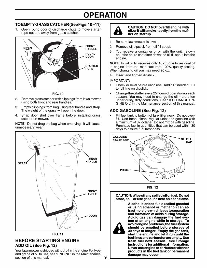
CAUTION: DO NOT overfi ll engine with oil, or it will smoke heavily from the muf-fl er on startup.
1. Be sure lawnmower is level. 2. Remove oil dipstick from oil fi ll spout.3. You receive a container of oil with the unit. Slowly
pour the entire container down the oil fi ll spout into the engine.
NOTE: Initial oil fi ll requires only 18 oz. due to residual oil in engine from the manufacturers 100% quality testing. When changing oil you may need 20 oz.4. Insert and tighten dipstick.
IMPORTANT:• Check oil level before each use. Add oil if needed. Fill
to full line on dipstick.• Change the oil after every 25 hours of operation or each
season. You may need to change the oil more often under dusty, dirty conditions. See “TO CHANGE EN-GINE OIL” in the Maintenance section of this manual.
ADD GASOLINE (See Fig. 12)• Fill fuel tank to bottom of tank fi ller neck. Do not over-
fi ll. Use fresh, clean, regular unleaded gasoline with a minimum of 87 octane. Do not mix oil with gasoline. Purchase fuel in quan ti ties that can be used within 30 days to assure fuel freshness.
OPERATIONTO EMPTY GRASS CATCHER (See Figs. 10 –11) 1. Open round door of discharge chute to move starter
rope out and away from grass catcher.
FIG. 10
ROUND DOOR
STARTER ROPE
OPENFRONT HANDLE
2. Remove grass catcher with clippings from lawn mower using both front and rear handles.
3. Empty clippings from bag using rear handle and strap. The weight of the grass will open the door.
4. Snap door shut over frame before installing grass catcher on mower.
NOTE: Do not drag the bag when emptying; it will cause unnecessary wear.
FIG. 11
FRONT HANDLE
REAR HANDLE
STRAP
DOOR
CAUTION: Wipe off any spilled oil or fuel. Do not store, spill or use gasoline near an open fl ame.
Alcohol blended fuels (called gasohol or using ethanol or methanol) can at-tract moisture which leads to separation and for ma tion of acids during storage. Acidic gas can damage the fuel sys-tem of an engine while in storage. To avoid engine problems, the fuel system should be emptied before stor age of 30 days or longer. Empty the gas tank, start the engine and let it run until the fuel lines and carburetor are empty. Use fresh fuel next season. See Storage In struc tions for additional information. Never use engine or carburetor cleaner products in the fuel tank or permanent damage may occur.
BEFORE STARTING ENGINEADD OIL (See Fig. 12)Your lawnmower is shipped without oil in the engine. For type and grade of oil to use, see “EN GINE” in the Maintenance section of this manual.
GASOLINE FILLER CAP OIL FILL
CAP
PRIMER
FIG. 12

10
TO STOP ENGINE• To stop engine, release operator presence con trol
bar.
TO START ENGINE NOTE: Due to protective coatings on the engine, a small amount of smoke may be present during the initial use of the product and should be considered normal.1. To start a cold engine, push primer three (3) times
before trying to start. Use a fi rm push. This step is not usually necessary when starting an engine which has already run for a few minutes.
2. Hold operator presence control bar down to the han dle and pull starter handle quickly. Do not allow starter rope to snap back.
NOTE: In cooler weather it may be necessary to repeat priming steps. In warmer weather over priming may cause fl ooding and engine will not start. If you do fl ood engine, wait a few minutes before attempting to start and do not repeat priming steps.
MOWING TIPS
CAUTION: Do not use de-thatcher blade attachments on your mower. Such at-tachments are hazardous, will damage your mower and could void your warranty.
• Under certain conditions, such as very tall grass, it may be necessary to raise the height of cut to reduce pushing effort and to keep from overloading the engine and leaving clumps of grass clippings. It may also be necessary to reduce ground speed and/or run the lawn mower over the area a second time.
• For extremely heavy cutting, reduce the width of cut by overlapping previously cut path and mow slowly.
• For better grass bagging and most cutting conditions, the engine speed should be set in the fast position.
• Pores in cloth grass catchers can become fi lled with dirt and dust with use and catchers will collect less grass. To prevent this, regularly hose catcher off with water and let dry before using.
• Keep top of engine around starter clear and clean of grass clippings and chaff. This will help engine air fl ow and extend engine life.
OPERATION
FIG. 13
MAX 1/3
MULCHING MOWING TIPSIMPORTANT: FOR BEST PERFORMANCE, KEEP MOWER HOUSING FREE OF BUILT-UP GRASS / TRASH. SEE “CLEANING” IN THE MAINTENANCE SECTION OF THIS MANUAL.
• The special mulching blade will recut the grass clip-pings many times and reduce them in size so that as they fall onto the lawn they will disperse into the grass and not be noticed. Also, the mulched grass will biode-grade quickly to provide nutrients for the lawn. Always mulch with your highest engine (blade) speed as this will provide the best recutting action of the blades.
• Avoid cutting your lawn when it is wet. Wet grass tends to form clumps and interferes with the mulching action. The best time to mow your lawn is the early afternoon. At this time the grass has dried, yet the newly cut area will not be exposed to direct sunlight.
• For best results, adjust the lawn mower cutting height so that the lawn mower cuts off only the top one-third of the grass blades (See Fig. 13). If the lawn is over-grown it will be necessary to raise the height of cut to reduce pushing effort and to keep from overloading the engine and leaving clumps of mulched grass. For extremely heavy mulching, reduce your width of cut by overlapping previously cut path and mow slowly.
• Certain types of grass and grass conditions may require that an area be mulched a second time to completely hide the clippings. When doing a second cut, mow across (perpendicular) to the fi rst cut path.
• Change your cutting pattern from week to week. Mow north to south one week then change to east to west the next week. This will help prevent matting and graining of the lawn.
11
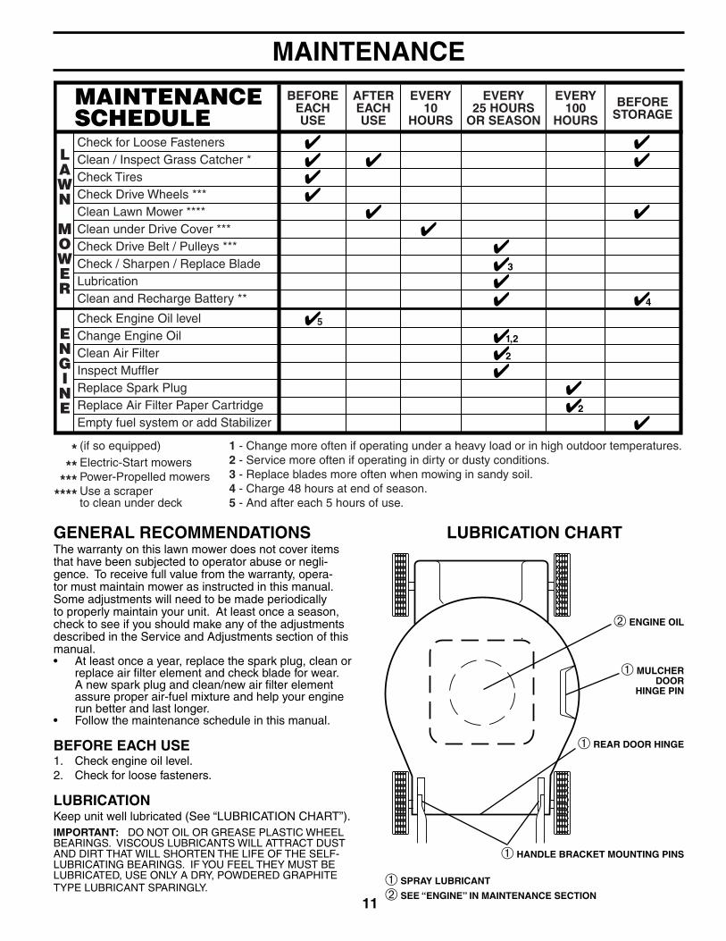
➁ ENGINE OIL
➀ HANDLE BRACK ET MOUNT ING PINS
➀ REAR DOOR HINGE
➀ MULCHER DOOR
HINGE PIN
Check for Loose FastenersClean / Inspect Grass Catcher *Check TiresCheck Drive Wheels ***Clean Lawn Mower ****Clean under Drive Cover ***Check Drive Belt / Pulleys ***Check / Sharpen / Replace BladeLubricationClean and Recharge Battery **
Check Engine Oil levelChange Engine OilClean Air FilterInspect MufflerReplace Spark PlugReplace Air Filter Paper CartridgeEmpty fuel system or add Stabilizer
BEFOREEACHUSE
AFTEREACHUSE
EVERY10
HOURS
EVERY25 HOURS
OR SEASON
EVERY100
HOURSBEFORE
STORAGE
1 - Change more often if operating under a heavy load or in high outdoor temperatures.2 - Service more often if operating in dirty or dusty conditions.3 - Replace blades more often when mowing in sandy soil.4 - Charge 48 hours at end of season.5 - And after each 5 hours of use.
(if so equipped)Electric-Start mowersPower-Propelled mowersUse a scraperto clean under deck
***
*******
MAINTENANCE
LUBRICATION CHARTGENERAL RECOMMENDATIONSThe warranty on this lawn mower does not cover items that have been subjected to operator abuse or negli-gence. To receive full value from the warranty, opera-tor must maintain mower as instructed in this manual. Some adjustments will need to be made periodically to properly maintain your unit. At least once a season, check to see if you should make any of the adjustments described in the Service and Ad just ments section of this manual.• At least once a year, replace the spark plug, clean or
replace air fi lter element and check blade for wear. A new spark plug and clean/new air fi lter element assure proper air-fuel mixture and help your engine run better and last longer.
• Follow the maintenance schedule in this manual.
BEFORE EACH USE1. Check engine oil level.2. Check for loose fasteners.
LUBRICATIONKeep unit well lubricated (See “LUBRICATION CHART”).IMPORTANT: DO NOT OIL OR GREASE PLASTIC WHEEL BEARINGS. VISCOUS LU BRI CANTS WILL ATTRACT DUST AND DIRT THAT WILL SHORT EN THE LIFE OF THE SELF-LU BRI CAT ING BEARINGS. IF YOU FEEL THEY MUST BE LU BRI CATED, USE ONLY A DRY, POW DERED GRAPHITE TYPE LUBRICANT SPAR INGLY. ➀ SPRAY LUBRICANT
➁ SEE “ENGINE” IN MAINTENANCE SECTION

12
LAWN MOWERAlways observe safety rules when performing any main- te nance.
TIRES• Keep tires free of gasoline, oil, or insect control chem-
i cals which can harm rubber.• Avoid stumps, stones, deep ruts, sharp objects and
other hazards that may cause tire damage.
DRIVE WHEELSCheck rear drive wheels each time be fore you mow to be sure they move freely.
The wheels not turning freely means trash, grass cuttings, etc. are in the drive wheel area and must be cleaned to free drive wheels.
If necessary to clean the drive wheels, be sure to clean both rear wheels.
BLADE CAREFor best results, mower blade must be kept sharp. Re place bent or dam aged blades.
CAUTION: Use only a replacement blade approved by the manufacturer of your mower. Using a blade not approved by the manufacturer of your mower is hazardous, could damage your mower and void your warranty.
TO REMOVE BLADE (See Fig. 14)1. Disconnect spark plug wire from spark plug and place
wire where it cannot come in contact with plug.2. Turn lawn mower on its side. Make sure air fi lter and
carburetor are up.3. Use a wood block between blade and mower hous ing
to prevent blade from turning when re mov ing blade bolt.
NOTE: Protect your hands with gloves and/or wrap blade with heavy cloth.4. Remove blade bolt by turning counter-clockwise. 5. Remove blade and attaching hardware (bolt, lock
wash er and hardened wash er).
TO REPLACE BLADE (See Fig. 14)1. Position blade on the blade adapter aligning the two
(2) holes in the blade with the raised lugs on the adapter.
2. Be sure the trailing edge of blade (opposite sharp edge) is up toward the engine.
3. Install the blade bolt with the lock washer and hard ened washer into blade adapter and crank shaft.
4. Use block of wood between blade and lawn mower housing and tighten the blade bolt, turning clock wise.
• The recommended tightening torque is 35-40 ft. lbs. IMPORTANT: BLADE BOLT IS HEAT TREATED. IF BOLT NEEDS REPLACING, REPLACE ONLY WITH APPROVED BOLT SHOWN IN THE REPAIR PARTS SECTION OF THIS MANUAL.
MAINTENANCE
TEMPERATURE RANGE ANTICIPATED BEFORE NEXT OIL CHANGE
SAE VISCOSITY GRADES
-20 0 30 40 80 100
-30 -20 0 20 30 40
F
C
32
-10 10
60
5W-30
SAE 30
FIG. 14
BLADE ADAPT ER
BLADE BOLT
HARDENEDWASHER
LOCK WASHER
BLADE
TRAILING EDGE
TO SHARPEN BLADENOTE: We do not recommend sharp en ing blade - but if you do, be sure the blade is balanced.
Care should be taken to keep the blade balanced. An un bal anced blade will cause eventual damage to lawn mower or engine. • The blade can be sharp ened with a fi le or on a grinding
wheel. Do not attempt to sharpen while on the mower.• To check blade balance, drive a nail into a beam or
wall. Leave about one inch of the straight nail ex posed. Place center hole of blade over the head of the nail. If blade is balanced, it should remain in a horizontal position. If either end of the blade moves downward, sharpen the heavy end until the blade is balanced.
GRASS CATCHER• The grass catcher may be hosed with water, but must
be dry when used.• Check your grass catcher often for damage or de te ri o -
ra tion. Through normal use it will wear. If catcher needs replacing, replace only with ap proved replacement catcher shown in the Repair Parts section of this manual. Give the lawn mower model number when ordering.
ENGINE
LUBRICATIONUse only high quality detergent oil rated with API service classifi cation SG–SL. Select the oil's SAE viscosity grade according to your expected operating temperature.
NOTE: Multi-viscosity oils (5W30, 10W30 etc.) improve starting in cold weather, and you should check your engine oil level frequently to avoid possible engine damage from running low on oil.

13
MAINTENANCEChange the oil after every 25 hours of operation or at least once a year if the lawn mower is not used for 25 hours in one year.
Check the crankcase oil level before starting the engine and after each fi ve (5) hours of continuous use. Tighten oil plug securely each time you check the oil level.
TO CHANGE ENGINE OIL (See Fig. 15)NOTE: Before tipping lawn mower to drain oil, empty fuel tank by running engine until fuel tank is empty.1. Disconnect spark plug wire from spark plug and place
wire where it cannot come in contact with plug.2. Remove engine oil cap; lay aside on a clean surface.3. Tip lawn mower on its side as shown and drain oil into
a suitable container. Rock lawn mower back and forth to remove any oil trapped inside of engine.
4. Wipe off any spilled oil from lawn mower or side of engine.
5. Slowly pour oil down the oil fi ll spout, stopping every few ounces to check the oil level with the dipstick.
6. Stop adding oil when you reach the FULL mark on the dipstick. Wait a minute to allow oil to settle.
7. Continue adding small amounts of oil, rechecking the dipstick until oil level settles at FULL. DO NOT over-fi ll, or engine will smoke heavily from the muffl er on startup.
8. Always be sure to retighten oil dipstick before starting engine.
9. Re con nect spark plug wire to spark plug.
AIR FILTER (See Fig. 16)Your engine will not run properly and may be damaged by using a dirty air fi lter. Replace the air fi lter cartridge every 100 hours of op er a tion or every season, which ev er occurs fi rst. Service air cleaner more often under dusty conditions.
TO CLEAN AIR FILTER1. Loosen screw and tilt cover to re move.2. Carefully remove cartridge.3. Clean by gently tapping on a fl at surface. If very dirty,
replace car tridge.
CONTAINER
FIG. 15
CAUTION: Pe tro leum solvents, such as ker o sene, are not to be used to clean car tridge. They may cause de te ri o ra tion of the cartridge. Do not oil car tridge. Do not use pres sur ized air to clean or dry car tridge.
4. Install cartridge, then replace cover making sure the tabs are aligned with the slots in the back plate. Fasten screw securely.
FIG. 16
SLOTS
LIP
COVER TABS
BACK PLATE
CARTRIDGE COVER
MUFFLERInspect and replace corroded muffl er as it could create a fi re hazard and/or damage.
SPARK PLUGReplace spark plug at the beginning of each mowing season or after every 100 hours of operation, whichever occurs fi rst. Spark plug type and gap setting are shown in the “PROD UCT SPEC I FI CA TIONS” section of this manual.
CLEANINGIMPORTANT: FOR BEST PERFORMANCE, KEEP MOWER HOUSING FREE OF BUILT-UP GRASS AND TRASH. CLEAN THE UNDERSIDE OF YOUR MOWER AFTER EACH USE.
CAUTION: Disconnect spark plug wire from spark plug and place wire where it cannot come in contact with plug.
• Clean the underside of your lawn mower by scraping to remove build-up of grass and trash.
• Clean engine often to keep trash from accumulating. A clogged engine runs hotter and shortens engine life.
• Keep fi nished surfaces and wheels free of all gasoline, oil, etc.
• We do not recommend using a garden hose to clean lawn mower unless the electrical system, muffl er, air fi lter and carburetor are covered to keep water out. Water in engine can result in shortened engine life.
CLEAN UNDER DRIVE COVERClean under drive cover at least twice a season. Scrape un-derside of cover with putty knife or similar tool to remove any build-up of trash or grass on underside of drive cover.

14
LAWN MOWERTO ADJUST CUTTING HEIGHTSee “TO ADJUST CUTTING HEIGHT” in the Operation section of this manual.
REAR DEFLECTORThe rear defl ector, attached between the rear wheels of your mower, is provided to minimize the possibility that objects will be thrown out of the rear of the mower into the operator's mowing position. If the defl ector becomes damaged, it should be replaced.
TO REMOVE DRIVE BELT (See Figs. 17–19)1. Disconnect spark plug wire from spark plug and place
wire where it cannot come in contact with plug.2. Remove screws retaining drive cover and remove drive
cover from lawn mower housing (See Fig. 17).
SERVICE AND ADJUSTMENTS
7. Use a wood block between blade and mower hous ing to prevent blade from turning when re mov ing blade bolt.
NOTE: Protect your hands with gloves and/or wrap blade with heavy cloth.8. Remove blade bolt. 9. Remove blade, attaching hardware (bolt, lock wash er,
hardened wash er), blade adapter and debris shield as one assembly.
10. Remove drive belt from blade adapter and debris shield; discard old belt.
TO REPLACE DRIVE BELT (See Figs. 17–20)1. Place new drive belt in the belt retainer of the debris
shield. Be sure to route belt between belt keepers and through slot as shown (See Fig. 20).
TRAILING EDGE
CRANKSHAFT
DEBRIS SHIELD
SCREW
BLADE ADAPTER
HARDENED WASHER
LOCK-WASHER
BLADE BOLT
TABHOUSING HOLE
FIG. 19
SCREWS
DRIVE COVER
LAWN MOWER
HOUSING
FIG. 173. Remove drive cable from anchor, then detach it and
return spring from idler arm assembly (See Fig. 18).
CAUTION: TO AVOID SERIOUS INJURY, BEFORE PERFORMING ANY SERVICE OR ADJUSTMENTS:1. Release control bar and stop engine.2. Make sure the blade and all moving parts have completely stopped.3. Disconnect spark plug wire from spark plug and place wire where it cannot come in contact
with plug.
4. Pivot idler arm assembly to slacken drive belt, then remove drive belt from drive pulley, belt keepers and idler arm.
5. Turn lawn mower on its side. Make sure air fi lter and carburetor are up.
6. Remove screw securing debris shield. Note that the debris shield has a tab which fi ts into a gap in the housing (See Fig. 19).
DEBRIS SHIELD
BELTRETAINER
BELT KEEPERS
DRIVE BELT
SLOT
TAB
FIG. 20
DRIVE CABLE ANCHOR
IDLER ARM ASSEMBLY
BELT KEEPER
DRIVE PULLEY
HOUSING HOLE
PIVOT
DRIVE BELT
FIG. 18
RETURN SPRING
15
STORAGEImmediately prepare your lawn mower for storage at the end of the season or if the unit will not be used for 30 days or more.
3. Be sure that all nuts, bolts, screws, and pins are se-curely fastened. Inspect moving parts for damage, breakage and wear. Replace if necessary.
4. Touch up all rusted or chipped paint surfaces; sand lightly before painting.
LAWN MOWERWhen lawn mower is to be stored for a period of time, clean it thoroughly, remove all dirt, grease, leaves, etc. Store in a clean, dry area.1. Clean entire lawn mower (See “CLEANING” in the
Maintenance section of this manual).2. Lubricate as shown in the Maintenance section of this
manual.
2. Route the other end of the new drive belt through hole in housing.
3. Reattach debris shield to housing with screw previ-ously removed. Be sure tab of debris shield is in gap of housing.
4. Position blade on the blade adapter aligning the two (2) holes in the blade with the raised lugs on the adapter.
5. Be sure the trailing edge of blade (opposite sharp edge) is up toward the engine as shown (See Fig. 19).
6. Install the blade bolt with the lock washer and hardened washer into blade adapter and crankshaft.
7. Use block of wood between blade and lawn mower housing and tighten the blade bolt, turning clockwise.
• The recommended tightening torque is 35-40 ft. lbs. IMPORTANT: BLADE BOLT IS HEAT TREATED. IF BOLT NEEDS REPLACING, REPLACE ONLY WITH APPROVED BOLT SHOWN IN THE REPAIR PARTS SECTION OF THIS MANUAL.
8. Return mower to upright position.9. Install new drive belt into idler arm assembly, then
around the drive pulley. Be sure belt is inside of belt keepers (See Fig. 18).
NOTE: Pulling on the drive belt (to install it on the drive pulley) will cause the other end of the belt to free itself from the debris shield retainer and come into contact with the pulley end of the blade adapter.10. Reattach drive cable and return spring to the idler arm
assembly, then reattach drive cable to anchor.11. Reattach drive cover with screws previously removed
(See Fig. 17).
12. Connect spark plug wire to spark plug.
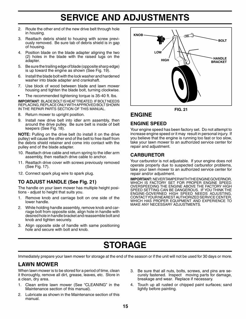
TO ADJUST HANDLE (See Fig. 21)The handle on your lawn mower has multiple height posi-tions - adjust to height that suits you.1. Remove knob and carriage bolt on one side of the
lower handle.2. While holding handle assembly, remove knob and car-
riage bolt from opposite side, align hole in handle with desired hole in handle bracket and reassemble bolt and knob and tighten securely.
3. Align opposite side of handle with same positioning hole and secure with bolt and knob.
SERVICE AND ADJUSTMENTS
ENGINE
ENGINE SPEEDYour engine speed has been factory set. Do not attempt to increase engine speed or it may result in personal injury. If you believe that the engine is running too fast or too slow, take your lawn mower to an authorized service center for repair and adjustment.
CARBURETORYour carburetor is not adjustable. If your engine does not operate properly due to suspected carburetor problems, take your lawn mower to an authorized service center for repair and/or adjustment.IMPORTANT: NEVER TAMPER WITH THE ENGINE GOVERNOR, WHICH IS FACTORY SET FOR PROPER ENGINE SPEED. OVER SPEED ING THE ENGINE ABOVE THE FACTORY HIGH SPEED SETTING CAN BE DANGEROUS. IF YOU THINK THE ENGINE-GOVERNED HIGH SPEED NEEDS ADJUSTING, CONTACT YOUR NEAREST AUTHORIZED SER VICE CEN TER, WHICH HAS PROPER EQUIP MENT AND EXPERIENCE TO MAKE ANY NEC ES SARY ADJUSTMENTS.
FIG. 21
HANDLE BRACKET
KNOB
BOLT
LOW
HIGH

16
FIG. 22
MOWINGPOSITIONOPERATOR
PRES ENCECONTROL BAR
FOLDFORWARD
FORSTORAGE
LOWER HANDLE
HANDLE KNOB
UPPER HANDLE
ENGINEFUEL SYSTEMIMPORTANT: IT IS IMPORTANT TO PREVENT GUM DEPOSITS FROM FORMING IN ESSENTIAL FUEL SYSTEM PARTS SUCH AS CARBURETOR, FUEL FILTER, FUEL HOSE, OR TANK DURING STORAGE. ALCOHOL BLENDED FUELS (CALLED GASOHOL OR USING ETHANOL OR METHANOL) CAN ATTRACT MOISTURE WHICH LEADS TO SEPARATION AND FORMATION OF ACIDS DURING STORAGE. ACIDIC GAS CAN DAMAGE THE FUEL SYSTEM OF AN ENGINE WHILE IN STORAGE.
• Empty the fuel tank by starting the engine and letting it run until the fuel lines and carburetor are empty.
• Never use engine or carburetor cleaner products in the fuel tank or permanent damage may occur.
• Use fresh fuel next season.
NOTE: Fuel stabilizer is an acceptable alternative in mini-mizing the formation of fuel gum deposits during stor age. Add stabilizer to gasoline in fuel tank or storage container. Always follow the mix ratio found on stabilizer container. Run engine at least 10 minutes after adding stabilizer to allow the stabilizer to reach the carburetor. Do not empty the gas tank and carburetor if using fuel stabilizer.
ENGINE OILDrain oil (with engine warm) and replace with clean en-gine oil. (See “ENGINE” in the Maintenance section of this manual).
CYLINDER1. Remove spark plug.2. Pour one ounce (29 ml) of oil through spark plug hole
into cylinder.3. Pull starter handle slowly a few times to distribute oil.4. Replace with new spark plug.
OTHER• Do not store gasoline from one season to another.• Replace your gasoline can if your can starts to rust.
Rust and/or dirt in your gasoline will cause problems.• If possible, store your unit indoors and cover it to give
protection from dust and dirt.• Cover your unit with a suitable protective cover that
does not retain moisture. Do not use plastic. Plastic cannot breathe, which allows condensation to form and will cause your unit to rust.
IMPORTANT: NEVER COVER MOWER WHILE ENGINE AND EXHAUST AREAS ARE STILL WARM.
CAUTION: Never store the lawn mower with gasoline in the tank inside a build- ing where fumes may reach an open fl ame or spark. Allow the engine to cool before storing in any enclosure.
STORAGEHANDLE (See Figs. 22 and 23)You can fold your lawn mower handle for storage.1. Loosen the two (2) handle knobs on sides of the upper
handle and allow handle to fold down to the rear.2. Remove the two (2) handle knobs and carriage bolts
on sides of the lower handle and pivot entire handle as sem bly forward and allow it to rest on mower.
3. Reinstall knobs and carriage bolts to lower handle or handle brackets for safe keeping.
• When setting up your handle from the storage posi-tion, you must manually lock the lower handle into the mowing position.
IMPORTANT: WHEN FOLDING THE HANDLE FOR STORAGE OR TRANSPORTATION, BE SURE TO FOLD THE HANDLE AS SHOWN OR YOU MAY DAMAGE THE CONTROL CABLES.
FIG. 23
HANDLE BRACKET
KNOB
BOLT

17
TROUBLESHOOTING POINTS
Does not start 1. Dirty air fi lter. 1. Clean/replace air fi lter. 2. Out of fuel. 2. Fill fuel tank. 3. Stale fuel. 3. Empty fuel tank and refi ll tank with fresh, clean gasoline. 4. Water in fuel. 4. Empty fuel tank and refi ll tank with fresh, clean gasoline. 5. Spark plug wire is disconnected. 5. Connect wire to plug. 6. Bad spark plug. 6. Replace spark plug. 7. Loose blade or broken blade adapter. 7. Tight en blade bolt or replace blade adapter. 8. Control bar in released position. 8. Depress control bar to handle. 9. Control bar defective. 9. Replace control bar. 10. Fuel valve lever (if equipped) in OFF position. 10. Turn fuel valve lever to the ON position. 11. Weak battery (if equipped). 11. Charge battery. 12. Disconnected battery connector (if equipped). 12. Connect battery to engine.
Loss of power 1. Rear of lawn mower housing or cutting 1. Raise cutting height. blade dragging in heavy grass. 2. Cutting too much grass. 2. Raise cutting height. 3. Dirty air fi lter. 3. Clean/replace air fi lter. 4. Buildup of grass, leaves and trash under 4. Clean underside of mower housing. mower. 5. Too much oil in engine. 5. Check oil level. 6. Walking speed too fast. 6. Cut at slower walking speed.
Poor cut – 1. Worn, bent or loose blade. 1. Replace blade. Tighten blade bolt.uneven 2. Wheel heights uneven. 2. Set all wheels at same height. 3. Buildup of grass, leaves and trash under 3. Clean underside of mower housing. mower.
Excessive 1. Worn, bent or loose blade. 1. Replace blade. Tighten blade bolt.vibration 2. Bent engine crankshaft. 2. Contact a Sears or qualifi ed service center.
Starter rope 1. Engine fl ywheel brake is on when control 1. Depress control bar to upper handle beforehard to pull bar is released. pulling starter rope. 2. Bent engine crankshaft. 2. Contact a Sears or qualifi ed service center. 3. Blade adapter broken. 3. Replace blade adapter. 4. Blade dragging in grass. 4. Move lawn mower to cut grass or other hard surface before starting.
Grass catcher 1. Cutting height too low. 1. Raise cutting height.not fi lling 2. Lift on blade worn off. 2. Replace blade. (if so equipped) 3. Catcher not venting air. 3. Clean grass catcher.
Hard to push 1. Grass is too high or wheel height is too low. 1. Raise cutting height. 2. Rear of lawn mower housing or cutting 2. Raise rear of lawn mower housing one (1) blade dragging in heavy grass. setting higher. 3. Grass catcher too full. 3. Empty grass catcher. 4. Handle height position not right for you. 4. Adjust handle height to suit.
Loss of drive 1. Belt wear. 1. Check/replace drive belt.(or slowing of 2. Belt off of pulley. 2. Check/reinstall drive belt.drive speed) 3. Drive cable worn or broken. 3. Put belt on pulleys / replace belts if broken. 4. “Loose” drive control system. 4. Adjust drive control.
PROBLEM CAUSE CORRECTION

18
ROTARY LAWN MOWER - - MODEL NUMBER 917.375940
19
ROTARY LAWN MOWER - - MODEL NUMBER 917.375940
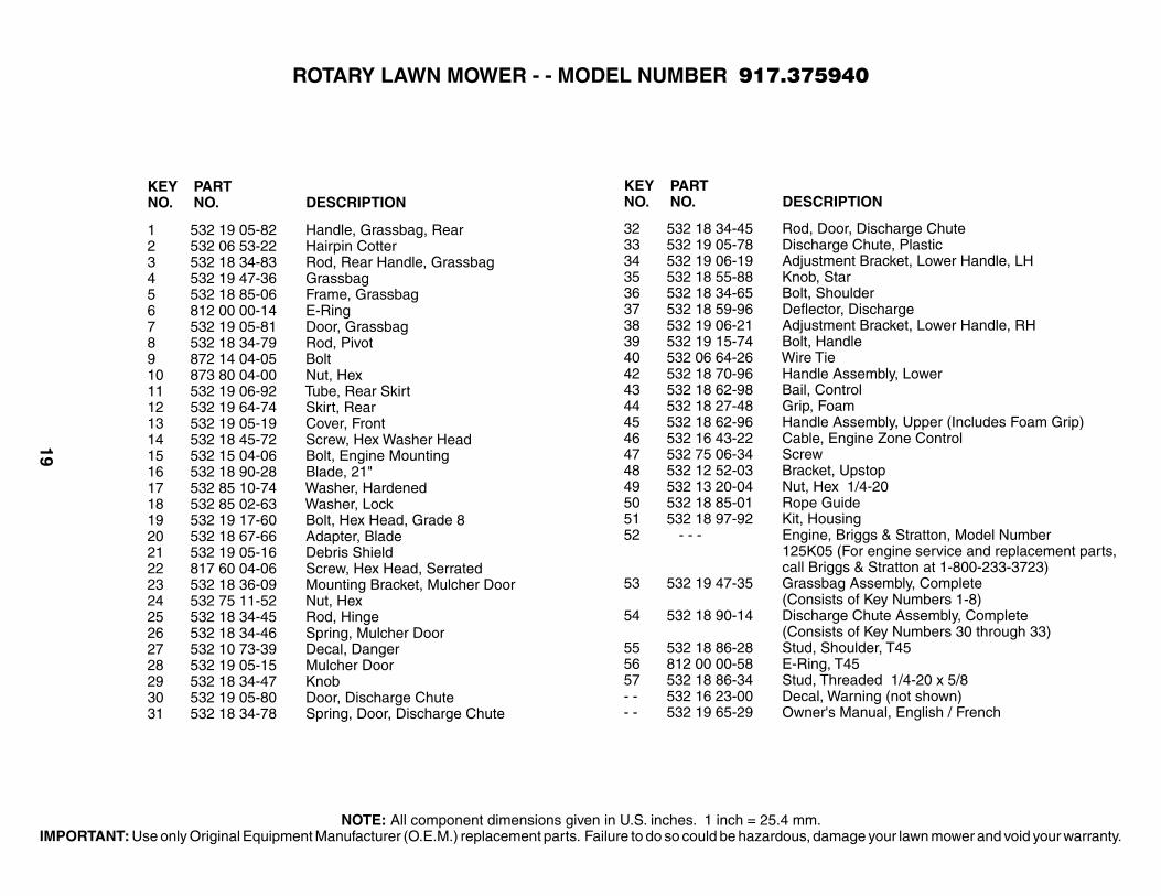
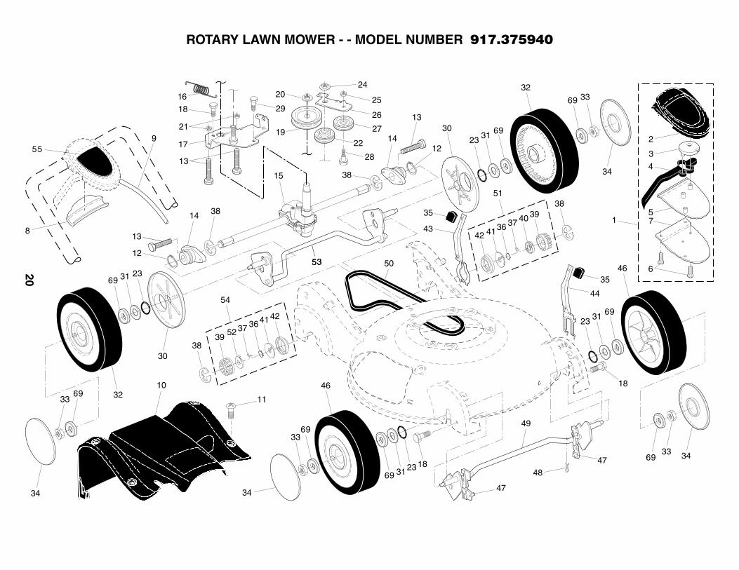
1 532 19 05-82 Handle, Grassbag, Rear 2 532 06 53-22 Hairpin Cotter3 532 18 34-83 Rod, Rear Handle, Grassbag4 532 19 47-36 Grassbag5 532 18 85-06 Frame, Grassbag6 812 00 00-14 E-Ring7 532 19 05-81 Door, Grassbag8 532 18 34-79 Rod, Pivot9 872 14 04-05 Bolt10 873 80 04-00 Nut, Hex11 532 19 06-92 Tube, Rear Skirt12 532 19 64-74 Skirt, Rear13 532 19 05-19 Cover, Front14 532 18 45-72 Screw, Hex Washer Head15 532 15 04-06 Bolt, Engine Mounting16 532 18 90-28 Blade, 21"17 532 85 10-74 Washer, Hardened18 532 85 02-63 Washer, Lock19 532 19 17-60 Bolt, Hex Head, Grade 820 532 18 67-66 Adapter, Blade21 532 19 05-16 Debris Shield22 817 60 04-06 Screw, Hex Head, Serrated23 532 18 36-09 Mounting Bracket, Mulcher Door24 532 75 11-52 Nut, Hex25 532 18 34-45 Rod, Hinge26 532 18 34-46 Spring, Mulcher Door27 532 10 73-39 Decal, Danger28 532 19 05-15 Mulcher Door29 532 18 34-47 Knob30 532 19 05-80 Door, Discharge Chute31 532 18 34-78 Spring, Door, Discharge Chute
32 532 18 34-45 Rod, Door, Discharge Chute33 532 19 05-78 Discharge Chute, Plastic34 532 19 06-19 Adjustment Bracket, Lower Handle, LH35 532 18 55-88 Knob, Star36 532 18 34-65 Bolt, Shoulder37 532 18 59-96 Defl ector, Discharge38 532 19 06-21 Adjustment Bracket, Lower Handle, RH39 532 19 15-74 Bolt, Handle40 532 06 64-26 Wire Tie42 532 18 70-96 Handle Assembly, Lower43 532 18 62-98 Bail, Control44 532 18 27-48 Grip, Foam45 532 18 62-96 Handle Assembly, Upper (Includes Foam Grip)46 532 16 43-22 Cable, Engine Zone Control47 532 75 06-34 Screw48 532 12 52-03 Bracket, Upstop49 532 13 20-04 Nut, Hex 1/4-2050 532 18 85-01 Rope Guide51 532 18 97-92 Kit, Housing52 - - - Engine, Briggs & Stratton, Model Number 125K05 (For engine service and replacement parts, call Briggs & Stratton at 1-800-233-3723)53 532 19 47-35 Grassbag Assembly, Complete (Consists of Key Numbers 1-8)54 532 18 90-14 Discharge Chute Assembly, Complete (Consists of Key Numbers 30 through 33)55 532 18 86-28 Stud, Shoulder, T4556 812 00 00-58 E-Ring, T4557 532 18 86-34 Stud, Threaded 1/4-20 x 5/8- - 532 16 23-00 Decal, Warning (not shown)- - 532 19 65-29 Owner's Manual, English / French
KEY PARTNO. NO. DESCRIPTION
KEY PARTNO. NO. DESCRIPTION
NOTE: All component dimensions given in U.S. inches. 1 inch = 25.4 mm.IMPORTANT: Use only Original Equipment Manufacturer (O.E.M.) replacement parts. Failure to do so could be hazardous, damage your lawn mower and void your warranty.
20
ROTARY LAWN MOWER - - MODEL NUMBER 917.375940

21
1 532 19 70-12 Drive Control Assembly, Complete (Consists of Key Numbers 2 through 7) 2 532 19 57-61 Cover, Drive Control, Top3 532 18 73-53 Pulley, Drive Control4 532 19 00-37 Lever, Drive Control (blue)5 532 19 57-62 Cover, Drive Control, Bottom6 532 18 16-98 Screw, Torx Head #8-5/87 532 18 70-97 Bracket, Mounting, Drive Control 8 532 18 62-97 Cap, Drive Control, Bottom9 532 19 70-11 Cable, Drive Control10 532 19 69-56 Cover Assembly, Drive11 532 18 45-71 Screw12 812 00 00-12 Ring, Retaining13 532 18 34-50 Screw14 532 18 71-20 Bearing / Axle Support 15 532 18 82-94 Gear Case Assembly (See Breakdown)16 532 19 41-24 Spring, Return17 532 19 68-22 Bracket, Gear Case / Drive Pulley18 532 16 34-09 Screw19 532 19 41-28 Pulley, Drive21 532 13 20-04 Nut, Hex22 532 19 37-91 Pulley Assembly, V-Groove23 532 18 81-52 O-Ring24 532 14 52-12 Nut, Hex, Flangelock25 873 93 05-00 Nut, Hex, Lock26 532 19 65-42 Idler Arm27 532 16 60-43 Pulley, Idler28 532 16 08-29 Bolt, Hex Head, Shoulder
29 817 06 04-10 Screw 1/4-20 x 1/1630 532 18 34-57 Cover, Dust, Wheel31 532 08 83-48 Washer, Flat 3/832 532 19 26-19 Wheel Assembly, Rear 9 x 2-1/433 532 08 39-23 Nut, Hex34 532 18 36-95 Hubcap35 532 18 59-94 Knob36 532 18 82-91 Spring, Torsion37 532 17 50-98 Pawl38 812 00 00-58 E-Ring39 532 17 51-03 Gear40 532 17 51-05 Retainer, Drive, LH41 532 17 51-04 Disc, Drive42 532 18 41-72 Seal, Friction43 532 19 05-20 Lever, Selector, Wheel Height, Rear44 532 19 05-18 Lever, Selector, Wheel Height, Front45 532 16 34-09 Screw46 532 19 22-30 Wheel Assembly, Front 9 x 2-1/447 532 18 34-38 Bushing, Front Axle48 532 16 96-75 Retainer, Hairpin Cotter49 532 19 64-69 Torque Shaft Assembly, Front50 532 18 36-88 Belt, Drive51 532 18 83-31 Pinion Assembly, LH52 532 17 51-02 Retainer, Drive, RH53 532 19 59-95 Rear Axle Assembly54 532 18 83-30 Pinion Assembly, RH55 532 18 90-74 Decal, Drive Control69 532 16 99-11 Bearing, Ball (Wheel)
KEY PARTNO. NO. DESCRIPTION
KEY PARTNO. NO. DESCRIPTION
ROTARY LAWN MOWER - - MODEL NUMBER 917.375940
NOTE: All component dimensions given in U.S. inches. 1 inch = 25.4 mm.IMPORTANT: Use only Original Equipment Manufacturer (O.E.M.) replacement parts. Failure to do so could be hazardous, damage your lawn mower and void your warranty.

22
ROTARY LAWN MOWER - - MODEL NUMBER 917.375940GEAR CASE ASSEMBLY - - PART NUMBER 532 18 82-94
KEY PART NO. NO. DESCRIPTION
1 532 18 75-30 Case, Lower2 532 19 12-45 Case, Upper3 532 18 75-32 Gear, 24 Teeth4 532 19 12-46 Shaft, Worm5 532 18 35-05 Wireform6 532 18 35-06 Bearing, Ball7 532 18 35-08 Seal, Output Shaft8 532 18 35-09 Washer9 532 18 35-11 Bushing10 532 19 12-47 Shaft, Output11 532 18 35-13 Screw12 532 18 35-14 Seal, Worm Shaft- - 532 75 03-69 Grease, Texaco Starplex Premium 1 (Do not substitute) (1.4 ounce capacity)
NOTE: All component dimensions given in U.S. inches. 1 inch = 25.4 mm. IMPORTANT: Use only Original Equipment Manu-facturer (O.E.M.) replacement parts. Failure to do so could be hazardous, damage your lawn mower and void your warranty.

23
SERVICE NOTES

24
SE
CT
ION
1:
LIM
ITE
D W
AR
RA
NT
Y
H
usqv
arna
For
est
& G
arde
n C
ompa
ny (
“Hus
qvar
na”)
war
rant
s H
usqv
arna
pro
duct
to
the
orig
inal
pur
-ch
aser
to
be f
ree
from
def
ects
in m
ater
ial a
nd w
orkm
ansh
ip f
rom
the
dat
e of
pur
chas
e fo
r th
e “W
arra
nty
Per
iod”
of
the
prod
uct
as s
et fo
rth
belo
w:
Lif
etim
e W
arra
nty
: A
ll til
ler
tines
aga
inst
bre
akag
e, t
rimm
er s
hafts
, ig
nitio
n co
ils a
nd m
odul
es o
n ha
nd
held
pro
d uct
.
3 Ye
ar W
arra
nty
: S
pind
les
(on
Zer
o Tu
rn R
ider
s an
d C
omm
erci
al W
alk-
Beh
inds
)
2 Ye
ar C
OM
ME
RC
IAL
-War
ran
ty:
Hus
qvar
na C
omm
erci
al T
urf
Equ
ipm
ent—
zero
tur
n rid
ers,
wid
e ar
ea
wal
ks,
and
grou
nd e
ngag
ing
com
mer
cial
equ
ipm
ent.
2 Ye
ar N
ON
-CO
MM
ER
CIA
L W
arra
nty
: A
utom
atic
Mow
er,
Rid
ing
law
n m
ower
s, y
ard
and
gard
en t
ract
ors,
w
alk
behi
nd m
ower
s, t
iller
s, c
hain
saw
s, t
rimm
ers,
bru
shcu
tters
, cl
earin
g sa
ws,
sno
w b
low
ers,
han
dhel
d bl
ower
s, b
ackp
ack
blow
ers,
hed
ge t
rimm
ers,
ele
ctric
al p
rodu
cts
and
pow
er-a
ssis
t co
llect
ion
syst
ems
for
non c
om m
er ci
al,
nonp
rofe
ssio
nal,
noni
nstit
utio
nal o
r no
ninc
ome
prod
ucin
g us
e, e
xcep
t as
her
ein
stat
ed.
E
mis
sion
con
trol
sys
tem
com
pone
nts
nece
ssar
y to
com
ply
with
CA
RB
-TIE
R-I
I an
d E
PA r
egul
atio
ns,
exce
pt fo
r th
ose
com
pone
nts
whi
ch a
re p
art o
f eng
ine
syst
ems
man
ufac
ture
d by
third
par
ty e
ngin
e m
anu-
fact
urer
s fo
r w
hich
the
pur
chas
er h
as r
ecei
ved
a se
para
te w
arra
nty
with
pro
duct
inf
orm
atio
n su
pplie
d at
tim
e of
pur
chas
e.
1 Ye
ar W
arra
nty
: P
ower
cut
ters
, stu
mp
grin
der,
pole
pru
ners
and
pol
e sa
ws
for
non-
com
mer
cial
, non
-pro
-fe
ssio
nal,
non-
inst
itutio
nal o
r no
n-in
com
e pr
oduc
ing
use.
All
trim
mer
s, b
rush
cutte
rs, c
lear
ing
saw
s, h
over
-in
g tr
imm
ers,
stic
k ed
gers
, bac
kpac
k bl
ower
s, h
and
held
blo
wer
s, h
edge
trim
mer
s, p
ower
-ass
ist c
olle
ctio
n sy
stem
s us
ed fo
r co
mm
erci
al,
inst
itutio
nal,
prof
essi
onal
or
inco
me
prod
ucin
g pu
rpos
es o
r us
e.
Bat
teri
es h
ave
a on
e-ye
ar p
rora
ted
limite
d w
arra
nty
with
100
% r
epla
cem
ent
durin
g th
e fi r
st 6
mon
ths.
90 D
ay W
arra
nty
: A
utom
atic
Mow
er,
Cha
in s
aws,
pow
er c
utte
rs,
stum
p gr
inde
rs,
pole
saw
s, p
ole
prun
-er
s, s
now
thr
ower
s, m
odel
ser
ies
580
& 6
00 w
alk-
behi
nd m
ower
s an
d co
mm
erci
al t
urf
equi
pmen
t or
any
H
usqv
arna
pro
duct
use
d fo
r co
mm
erci
al,
inst
itutio
nal,
prof
essi
onal
, or
inco
me
prod
ucin
g pu
rpos
es o
r us
e ex
cept
as
othe
rwis
e pr
ovid
ed h
erei
n.
Hu
sqva
rna
Saf
ety
Ap
par
el c
arrie
s a
90-d
ay w
arra
nty
from
the
dat
e of
the
cus
tom
er’s
orig
inal
pur
chas
e fo
r de
fect
s in
mat
eria
l and
wor
kman
ship
. Nor
mal
wea
r, te
ar o
r ab
use
is n
ot c
over
ed u
nder
war
rant
y. P
rod-
uct
mus
t be
ret
urne
d to
Cha
rlotte
with
a w
arra
nty
clai
m fo
rm. A
ll ca
re a
nd m
aint
enan
ce in
stru
ctio
ns m
ust
be f
ollo
wed
as
stat
ed b
y th
e m
anuf
actu
rer
on t
he c
are
labe
l. T
he fi
t of
the
pro
tect
ive
appa
rel/b
oot
is n
ot
cove
red
unde
r w
arra
nty.
30 D
ay W
arra
nty
: R
epla
cem
ent
part
s, a
cces
sorie
s in
clud
ing
bars
and
cha
ins,
too
ls a
nd d
ispl
ay it
ems.
SE
CT
ION
2:
HU
SQ
VAR
NA
’S O
BL
IGA
TIO
NS
UN
DE
R T
HE
WA
RR
AN
TY
H
usqv
arna
will
rep
air
or r
epla
ce d
efec
tive
com
pone
nts
with
out c
harg
e fo
r pa
rts
or la
bor
if a
com
pone
nt
fails
bec
ause
of
a de
fect
in m
ater
ial o
r w
orkm
ansh
ip d
urin
g th
e w
arra
nty
perio
d.
SE
CT
ION
3:
ITE
MS
NO
T C
OV
ER
ED
BY
TH
IS W
AR
RA
NT
Y
The
follo
win
g ite
ms
are
not
cove
red
by t
his
war
rant
y:(1
)Nor
mal
cus
tom
er m
aint
enan
ce it
ems
whi
ch b
ecom
e w
orn
thro
ugh
norm
al r
egul
ar u
se,
incl
udin
g, b
ut
n
ot li
mite
d to
, be
lts,
blad
es,
blad
e ad
apte
rs,
bulb
s, fi
lters
, gu
ide
bars
, lu
bric
ants
, re
win
d sp
rings
, sa
w
c
hain
, sp
ark
plug
s, s
tart
er r
opes
and
tin
es;
(2)N
atur
al d
isco
lora
tion
of m
ater
ial d
ue t
o ul
trav
iole
t lig
ht;
(3)E
ngin
e an
d dr
ive
syst
ems
not
man
ufac
ture
d by
Hus
qvar
na; t
hese
item
s ar
e co
vere
d by
the
res
pect
ive
man
ufac
ture
r’s w
arra
nty
as p
rovi
ded
in w
ritin
g w
ith t
he p
rodu
ct in
form
atio
n su
pplie
d at
the
tim
e of
pur
-
cha
se; a
ll cl
aim
s m
ust
be s
ent
to t
he a
ppro
pria
te m
anuf
actu
rer;
(4)L
awn
and
gard
en a
ttach
men
ts a
re c
over
ed b
y a
third
par
ty w
hich
giv
es a
war
rant
y, a
ll cl
aim
s fo
r w
ar-
r
anty
sho
uld
be s
ent
to t
he m
anuf
actu
rer;
and
(5)E
mis
sion
Con
trol
Sys
tem
com
pone
nts
nece
ssar
y to
com
ply
with
CA
RB
-TIE
R-I
I an
d E
PA r
egul
atio
ns
w
hich
are
man
ufac
ture
d by
thi
rd p
arty
eng
ine
man
ufac
ture
r.
SE
CT
ION
4:
EX
CE
PT
ION
S A
ND
LIM
ITA
TIO
NS
Thi
s w
arra
nty
shal
l be
inap
plic
able
to
defe
cts
resu
lting
fro
m t
he fo
llow
ing:
(
1)A
ccid
ent,
abus
e, m
isus
e, n
eglig
ence
and
neg
lect
, in
clud
ing
stal
e fu
el,
dirt
, ab
rasi
ves,
moi
stur
e, r
ust,
corr
osio
n, o
r an
y ad
vers
e re
actio
n du
e to
inco
rrec
t st
orag
e or
use
hab
its;
(
2)Fa
ilure
to
oper
ate
or m
aint
ain
the
unit
in a
ccor
danc
e w
ith t
he O
wne
r’s/O
pera
tor’s
man
ual o
r in
stru
c-
tio
n sh
eet
furn
ishe
d by
Hus
qvar
na;
(
3)A
ltera
tions
or
mod
ifi ca
tions
tha
t ch
ange
the
inte
nded
use
of
the
prod
uct
or a
ffect
s th
e pr
oduc
t’s p
er-
fo
rman
ce,
oper
atio
n, s
afet
y, o
r du
rabi
lity,
or
caus
es t
he p
rodu
ct t
o fa
il to
com
ply
with
any
app
licab
le
la
ws;
or:
(4)
Add
ition
al d
amag
e to
par
ts o
r co
mpo
nent
s du
e to
con
tinue
d us
e oc
curr
ing
afte
r an
y of
the
abo
ve.
RE
PAIR
OR
RE
PLA
CE
ME
NT
AS
PR
OV
IDE
D U
ND
ER
TH
IS W
AR
RA
NT
Y IS
TH
E E
XC
LUS
IVE
RE
ME
DY
OF
T
HE
PU
R C
HA
S E
R. H
US
QV
AR
NA
SH
ALL
NO
T B
E L
IAB
LE F
OR
AN
Y IN
CID
EN
TAL
OR
CO
NS
EQ
UE
NT
IAL
DA
MA
GE
S F
OR
BR
EA
CH
OF
AN
Y E
XP
RE
SS
OR
IMP
LIE
D W
AR
RA
NT
Y O
N T
HE
SE
PR
OD
UC
TS
EX
CE
PT
TO
TH
E E
XT
EN
T P
RO
HIB
ITE
D B
Y A
PP
LIC
AB
LE L
AW
. AN
Y I
MP
LIE
D W
AR
RA
NT
Y O
F M
ER
CH
AN
TAB
IL-
ITY
OR
FIT
NE
SS
FO
R A
PA
RT
ICU
LAR
PU
RP
OS
E O
N T
HE
SE
PR
OD
UC
TS
IS L
IMIT
ED
IN D
UR
ATIO
N T
O
TH
E W
AR
RA
NT
Y P
ER
IOD
AS
DE
FIN
ED
IN
TH
E L
IMIT
ED
WA
RR
AN
TY
STA
TE
ME
NT.
HU
SQ
VA
RN
A R
E-
SE
RV
ES
TH
E R
IGH
T T
O C
HA
NG
E O
R I
MP
RO
VE
TH
E D
ES
IGN
OF
TH
E P
RO
DU
CT
WIT
HO
UT
NO
TIC
E,
AN
D D
OE
S N
OT
AS
SU
ME
OB
LIG
ATIO
N T
O U
PD
ATE
PR
EV
IOU
SLY
MA
NU
FAC
TU
RE
D P
RO
D U
CT
S.
S
ome
stat
es d
o no
t allo
w th
e ex
clus
ion
of in
cide
ntal
or
cons
eque
ntia
l dam
ages
, or
limita
tions
on
how
long
an
impl
ied
war
rant
y la
sts,
so
the
abov
e lim
itatio
ns o
r ex
clus
ions
may
not
app
ly t
o yo
u. T
his
war
rant
y gi
ves
you
spec
ifi c
lega
l rig
hts,
and
you
may
als
o ha
ve o
ther
rig
hts
whi
ch v
ary
from
sta
te t
o st
ate.
SE
CT
ION
5:
CU
STO
ME
R R
ES
PO
NS
IBIL
ITIE
S
T
he p
rodu
ct m
ust e
xhib
it re
ason
able
car
e, m
aint
enan
ce, o
pera
tion,
sto
rage
and
gen
eral
upk
eep
as w
ritte
n in
the
mai
nten
ance
sec
tion
of th
e O
wne
r’s/O
pera
tor’s
man
ual.
Sho
uld
an o
pera
tiona
l pro
blem
or
failu
re o
ccur
, th
e pr
oduc
t sh
ould
not
be
used
, bu
t de
liver
ed a
s is
to
an a
utho
rized
Hus
qvar
na d
eale
r fo
r ev
alua
tion.
Pro
of
of p
urch
ase,
as
expl
aine
d in
sec
tion
6, r
ests
sol
ely
with
the
cus
tom
er.
SE
CT
ION
6:
PR
OC
ED
UR
E T
O O
BTA
IN W
AR
RA
NT
Y C
ON
SID
ER
AT
ION
I
t is
the
Ow
ner’s
and
Dea
ler’s
res
pons
ibili
ty to
mak
e ce
rtai
n th
at th
e W
arra
nty
Reg
istr
atio
n C
ard
is p
rope
rly
fi lle
d ou
t and
mai
led
to H
usqv
arna
For
est &
Gar
den
Com
pany
. Thi
s ca
rd s
houl
d be
mai
led
with
in te
n (1
0) d
ays
from
the
dat
e of
pur
chas
e in
ord
er t
o co
nfi r
m t
he w
arra
nty
and
to fa
cilit
ate
post
-sal
e se
rvic
e.
P
roof
of p
urch
ase
mus
t be
pres
ente
d to
the
auth
oriz
ed H
usqv
arna
dea
ler
in o
rder
to o
btai
n w
arra
nty
ser-
vice
. Thi
s pr
oof m
ust i
nclu
de d
ate
purc
hase
d, m
odel
num
ber,
seria
l num
ber,
and
com
plet
e na
me
and
addr
ess
of t
he s
ellin
g de
aler
.
T
o ob
tain
the
ben
efi t
of t
his
war
rant
y, t
he p
rodu
ct b
elie
ved
to b
e de
fect
ive
mus
t be
del
iver
ed t
o an
au-
thor
ized
Hus
qvar
na d
eale
r in
a t
imel
y m
anne
r, no
lat
er t
han
thir
ty (
30)
days
fro
m d
ate
of t
he o
pera
tiona
l pr
oble
m o
r fa
ilure
. The
pro
duct
mus
t be
del
iver
ed a
t th
e ow
ner’s
exp
ense
. Pic
k-up
and
del
iver
y ch
arge
s ar
e no
t co
vere
d by
thi
s w
arra
nty.
An
auth
oriz
ed H
usqv
arna
dea
ler
can
be n
orm
ally
loca
ted
thro
ugh
the
“Yel
low
P
ages
” of
the
loca
l tel
epho
ne d
irect
ory
or b
y ca
lling
1-8
00-H
US
KY
62 fo
r a
deal
er in
you
r ar
ea.
HU
SQ
VAR
NA
73
49 S
tate
svill
e R
oad
Ch
arlo
tte,
NC
28
269
531
83 8
1-23
2002
WA
RR
AN
TY
STA
TE
ME
NT


