30
Lecture Notes in Electrical Engineering 699 Om Hari Gupta Vijay Kumar Sood Editors Recent Advances in Power Systems Select Proceedings of EPREC 2020
Lecture Notes in Electrical Engineering 699
Om Hari GuptaVijay Kumar Sood Editors
Recent Advances in Power SystemsSelect Proceedings of EPREC 2020

Lecture Notes in Electrical Engineering
Volume 699
Series Editors
Leopoldo Angrisani, Department of Electrical and Information Technologies Engineering, University of NapoliFederico II, Naples, ItalyMarco Arteaga, Departament de Control y Robótica, Universidad Nacional Autónoma de México, Coyoacán,MexicoBijaya Ketan Panigrahi, Electrical Engineering, Indian Institute of Technology Delhi, New Delhi, Delhi, IndiaSamarjit Chakraborty, Fakultät für Elektrotechnik und Informationstechnik, TU München, Munich, GermanyJiming Chen, Zhejiang University, Hangzhou, Zhejiang, ChinaShanben Chen, Materials Science and Engineering, Shanghai Jiao Tong University, Shanghai, ChinaTan Kay Chen, Department of Electrical and Computer Engineering, National University of Singapore,Singapore, SingaporeRüdiger Dillmann, Humanoids and Intelligent Systems Laboratory, Karlsruhe Institute for Technology,Karlsruhe, GermanyHaibin Duan, Beijing University of Aeronautics and Astronautics, Beijing, ChinaGianluigi Ferrari, Università di Parma, Parma, ItalyManuel Ferre, Centre for Automation and Robotics CAR (UPM-CSIC), Universidad Politécnica de Madrid,Madrid, SpainSandra Hirche, Department of Electrical Engineering and Information Science, Technische UniversitätMünchen, Munich, GermanyFaryar Jabbari, Department of Mechanical and Aerospace Engineering, University of California, Irvine,CA, USALimin Jia, State Key Laboratory of Rail Traffic Control and Safety, Beijing Jiaotong University, Beijing, ChinaJanusz Kacprzyk, Systems Research Institute, Polish Academy of Sciences, Warsaw, PolandAlaa Khamis, German University in Egypt El Tagamoa El Khames, New Cairo City, EgyptTorsten Kroeger, Stanford University, Stanford, CA, USAQilian Liang, Department of Electrical Engineering, University of Texas at Arlington, Arlington, TX, USAFerran Martín, Departament d’Enginyeria Electrònica, Universitat Autònoma de Barcelona, Bellaterra,Barcelona, SpainTan Cher Ming, College of Engineering, Nanyang Technological University, Singapore, SingaporeWolfgang Minker, Institute of Information Technology, University of Ulm, Ulm, GermanyPradeep Misra, Department of Electrical Engineering, Wright State University, Dayton, OH, USASebastian Möller, Quality and Usability Laboratory, TU Berlin, Berlin, GermanySubhas Mukhopadhyay, School of Engineering & Advanced Technology, Massey University,Palmerston North, Manawatu-Wanganui, New ZealandCun-Zheng Ning, Electrical Engineering, Arizona State University, Tempe, AZ, USAToyoaki Nishida, Graduate School of Informatics, Kyoto University, Kyoto, JapanFederica Pascucci, Dipartimento di Ingegneria, Università degli Studi “Roma Tre”, Rome, ItalyYong Qin, State Key Laboratory of Rail Traffic Control and Safety, Beijing Jiaotong University, Beijing, ChinaGan Woon Seng, School of Electrical & Electronic Engineering, Nanyang Technological University,Singapore, SingaporeJoachim Speidel, Institute of Telecommunications, Universität Stuttgart, Stuttgart, GermanyGermano Veiga, Campus da FEUP, INESC Porto, Porto, PortugalHaitao Wu, Academy of Opto-electronics, Chinese Academy of Sciences, Beijing, ChinaJunjie James Zhang, Charlotte, NC, USA

The book series Lecture Notes in Electrical Engineering (LNEE) publishes thelatest developments in Electrical Engineering - quickly, informally and in highquality. While original research reported in proceedings and monographs hastraditionally formed the core of LNEE, we also encourage authors to submit booksdevoted to supporting student education and professional training in the variousfields and applications areas of electrical engineering. The series cover classical andemerging topics concerning:
• Communication Engineering, Information Theory and Networks• Electronics Engineering and Microelectronics• Signal, Image and Speech Processing• Wireless and Mobile Communication• Circuits and Systems• Energy Systems, Power Electronics and Electrical Machines• Electro-optical Engineering• Instrumentation Engineering• Avionics Engineering• Control Systems• Internet-of-Things and Cybersecurity• Biomedical Devices, MEMS and NEMS
For general information about this book series, comments or suggestions, pleasecontact [email protected].
To submit a proposal or request further information, please contact thePublishing Editor in your country:
China
Jasmine Dou, Associate Editor ([email protected])
India, Japan, Rest of Asia
Swati Meherishi, Executive Editor ([email protected])
Southeast Asia, Australia, New Zealand
Ramesh Nath Premnath, Editor ([email protected])
USA, Canada:
Michael Luby, Senior Editor ([email protected])
All other Countries:
Leontina Di Cecco, Senior Editor ([email protected])
** Indexing: The books of this series are submitted to ISI Proceedings,EI-Compendex, SCOPUS, MetaPress, Web of Science and Springerlink **
More information about this series at http://www.springer.com/series/7818
Om Hari Gupta • Vijay Kumar SoodEditors
Recent Advances in PowerSystemsSelect Proceedings of EPREC 2020
123
EditorsOm Hari GuptaDepartment of Electrical EngineeringNational Institute of TechnologyJamshedpurJamshedpur, India
Vijay Kumar SoodFaculty of Engineering and Applied ScienceOntario Tech UniversityOshawa, ON, Canada
ISSN 1876-1100 ISSN 1876-1119 (electronic)Lecture Notes in Electrical EngineeringISBN 978-981-15-7993-6 ISBN 978-981-15-7994-3 (eBook)https://doi.org/10.1007/978-981-15-7994-3
© The Editor(s) (if applicable) and The Author(s), under exclusive license to Springer NatureSingapore Pte Ltd. 2021This work is subject to copyright. All rights are solely and exclusively licensed by the Publisher, whetherthe whole or part of the material is concerned, specifically the rights of translation, reprinting, reuse ofillustrations, recitation, broadcasting, reproduction on microfilms or in any other physical way, andtransmission or information storage and retrieval, electronic adaptation, computer software, or by similaror dissimilar methodology now known or hereafter developed.The use of general descriptive names, registered names, trademarks, service marks, etc. in thispublication does not imply, even in the absence of a specific statement, that such names are exempt fromthe relevant protective laws and regulations and therefore free for general use.The publisher, the authors and the editors are safe to assume that the advice and information in thisbook are believed to be true and accurate at the date of publication. Neither the publisher nor theauthors or the editors give a warranty, expressed or implied, with respect to the material containedherein or for any errors or omissions that may have been made. The publisher remains neutral with regardto jurisdictional claims in published maps and institutional affiliations.
This Springer imprint is published by the registered company Springer Nature Singapore Pte Ltd.The registered company address is: 152 Beach Road, #21-01/04 Gateway East, Singapore 189721,Singapore
Preface
The Electric Power and Renewable Energy Conference (EPREC-2020), organizedby the Department of Electrical Engineering, National Institute of TechnologyJamshedpur, India, during May 29 to 30, 2020, has been a unique conferenceduring the difficult times of a global pandemic necessitating the usage of onlinepresentations. We thank all the contributors for maintaining the high standard andmaking EPREC-2020 a huge success. Out of total 351 valid submissions, only 142were selected for publication in three different volumes, i.e., an acceptance rate ofnearly 40%. The conference attracted an international audience from the followingcountries: Bangladesh, Brazil, Canada, China, India, Norway, Qatar, Slovakia,Thailand, Ukraine, and USA. This volume, i.e., Recent Advances in Power System,is one of three volumes published by Springer in the book series “Lecture Notes inElectrical Engineering (LNEE).” It contains 49 high-quality papers which providean overview of recent developments in modern power systems.
We thank all the organizing committee members, technical program committeemembers, reviewers, and student volunteers for their valuable support and volunteerwork. We also appreciate the role of session chairs/co-chairs. We also thank theseries editors of LNEE and Ms. Priya Vyas and Dr. Akash Chakraborty, AssociateEditors—Applied Sciences and Engineering, Springer, for their help and quickresponses during the preparation of the volume.
The editors hope that this volume will provide the readers relevant informationon the latest trends in renewable energy, microgrid/smart grid operation, control,protection, HVDC systems, power system protection, etc.
Jamshedpur, India Om Hari GuptaOshawa, Canada Vijay Kumar Sood
v
Contents
Ground Fault Detection Using Pole Differential Current Measurementfor 2-Terminal Bipolar HVDC Lines . . . . . . . . . . . . . . . . . . . . . . . . . . . 1Ravi Shankar Tiwari, Om Hari Gupta, and Vijay K. Sood
A Review on Islanding Detection Schemes for DC Microgrids . . . . . . . . 15Bhabani Kumari Choudhury and Premalata Jena
Novel Fault Detection Scheme Using Stockwell Transformfor Transmission Lines with Wind Power Penetration . . . . . . . . . . . . . . 27Nishant Saxena, Rachit Saxena, and Krishna Murari
Optimization of Load Distribution Between Distributed GenerationUnits of a Similar Technology Using Dynamic Programming . . . . . . . . 39Illia Diahovchenko and Anastasiia Horbul
Improvement of Voltage Regulation in an IEEE 9-Bus RadialMicrogrid Feeder Using Regression Model . . . . . . . . . . . . . . . . . . . . . . 51Yuvraj Praveen Soni and Eugene Fernandez
Optimal Power Dispatch of Renewable Energy-Based Microgridwith AC/DC Constraints . . . . . . . . . . . . . . . . . . . . . . . . . . . . . . . . . . . . 59Sunil Kumar and G. L. Pahuja
An Overview of Implementation Issues of Smart Grid . . . . . . . . . . . . . . 77Mayank Srivastava
A Performance Evaluation of SO2 Gas and SO2/CO2 Gas Mixtureas Potential SF6 Gas Alternatives in Power Transmissionand Distribution System . . . . . . . . . . . . . . . . . . . . . . . . . . . . . . . . . . . . . 85Akhilesh Kumar Pandey, Pushpendra Singh, Jitendra Kumar Singh,and Shahnawaz Khan
An Islanding Detection Methodology for SOFC-Based Static DGUsing DWT . . . . . . . . . . . . . . . . . . . . . . . . . . . . . . . . . . . . . . . . . . . . . . 95Salauddin Ansari, Om Hari Gupta, and Manoj Tripathy
vii
A Novel Firing Angle-Based Power-Flow Model of TCSC . . . . . . . . . . . 109Palak, Pawan Yadav, Vedant Tiwari, and Suman Bhowmick
Impact of Responsive Demand Scheduling on Optimal Operationof Smart Reconfigurable Distribution System . . . . . . . . . . . . . . . . . . . . 117Tanuj Rawat, K. R. Niazi, Nikhil Gupta, and Sachin Sharma
Optimal Sharing of Real Power Using Robust Controllerin Multi-terminal DC Systems . . . . . . . . . . . . . . . . . . . . . . . . . . . . . . . . 127Himanshu Singh, Suyash Singh, Sheetla Prasad, and Lokesh Garg
Voltage Ripple-Based Islanding Technique on Modified IEEE-13 BusTest Feeder for Photovoltaic Inverter . . . . . . . . . . . . . . . . . . . . . . . . . . 139Salauddin Ansari and Om Hari Gupta
Overview of Electric Vehicle: Opportunities and Challengeswith Smart Grid . . . . . . . . . . . . . . . . . . . . . . . . . . . . . . . . . . . . . . . . . . . 157Atma Ram Gupta, Rishabh Gupta, Saurav, Aditya Tiwari,and Ranjana Purohit
HVDC Transmission Topology and Control Analysis . . . . . . . . . . . . . . 171Ravi Shankar Tiwari
Modeling and Simulation of Photovoltaic Solar Cell Microgrid . . . . . . . 181Munna Kumar, Kanak Bhengra, and Jitendra Kumar
Effect of Electrical Vehicles Charging on Distribution Systemwith Distributed Generation . . . . . . . . . . . . . . . . . . . . . . . . . . . . . . . . . . 191Nilesh Bhut and Bhargav Vyas
Renewable Power Generation Using Asynchronous Generator:A Review . . . . . . . . . . . . . . . . . . . . . . . . . . . . . . . . . . . . . . . . . . . . . . . . 205Nagendra Singh, Ritesh Tirole, Shekh Kulsum Almas, and Dimpy Sood
Estimation of the Monthly Standard Diffuse and Universal SolarEradiation for the City Varanasi, Uttar Pradesh, India . . . . . . . . . . . . . 217Munna Kumar, Nalini Singh, and Jitendra Kumar
Evaluation of Residual Inductance of the Impulse Generatorfor the Generation of Lightning Impulse Voltage . . . . . . . . . . . . . . . . . . 223Nidhi Chandrakar, Chadaram Chandra Sekhar, and K. Chandrasekaran
Optimal Placement of PMUs for Kerala and Tamil Nadu State LevelRegional Indian Power Grid . . . . . . . . . . . . . . . . . . . . . . . . . . . . . . . . . 233Chadaram Chandra Sekhar and P. Suresh Babu
Study of Phasor Measurement Unit and Its Applications . . . . . . . . . . . . 247Shiv Shankar, K. B. Yadav, Alok Priyadarshi, and Vishal Rathore
viii Contents
Optimal Placement of Electric Vehicle Charging StationsUsing JAYA Algorithm . . . . . . . . . . . . . . . . . . . . . . . . . . . . . . . . . . . . . 259Ajit Kumar Mohanty and P. Suresh Babu
PSO Based Optimal Reactive Power Dispatch for the Enrichmentof Power System Performance . . . . . . . . . . . . . . . . . . . . . . . . . . . . . . . . 267K. Manasvi, B. Venkateswararao, Ramesh Devarapalli,and Upendra Prasad
Design of Adaptive Distance Relay for Transmission Line Protectionwith Wind Power Integration . . . . . . . . . . . . . . . . . . . . . . . . . . . . . . . . . 277Venkata Rao Nikhil Garlapati, Sujo Palamoottil George, and Ashok Sankar
Superimposed Components Based Directional Relaying DuringPower Swing . . . . . . . . . . . . . . . . . . . . . . . . . . . . . . . . . . . . . . . . . . . . . 289Shashi Bhushan Chandel, Lakshman Saroj, Kumar Harshavardhana,Himanshu Shekhar, and Jitendra Kumar
Energy Audit of Hybrid (Grid, Solar Rooftop Photovoltaic Systemand Diesel Generator) Electric Power Supply System: A Case Studyof Commercial Building . . . . . . . . . . . . . . . . . . . . . . . . . . . . . . . . . . . . . 299Abhishek Pratap Singh, Aditya Singhal, Akanksha Athaya,Saurabh Kumar Rajput, Laxmi Srivastava, and Vikas Sharma
A Comparative Analysis of EVs Scheduling Strategiesto Accomplish Valley Filling . . . . . . . . . . . . . . . . . . . . . . . . . . . . . . . . . . 311Tanuj Rawat, K. R. Niazi, Nikhil Gupta, and Sachin Sharma
Islanding Detection Through Mean of Superimposed Voltage . . . . . . . . 319Kanak Bhengra, Munna Kumar, and Jitendra Kumar
Application of Admittance-Based Relaying Scheme Under DynamicShunt Compensation . . . . . . . . . . . . . . . . . . . . . . . . . . . . . . . . . . . . . . . 327Jai Prakash Sharma, Shaili Shaw, and Om Hari Gupta
Wind Potential Assessment for Micropower Generation in TropicalWet Climate of India . . . . . . . . . . . . . . . . . . . . . . . . . . . . . . . . . . . . . . . 337Santoshkumar Hampannavar, K. N. Patil, Swapna Manasani,R. Yaragatti Udaykumar, Rajashekar P. Mandi, and C. Nandakumar
Analysis of a Grid-Connected PV System Located in EducationalInstitution . . . . . . . . . . . . . . . . . . . . . . . . . . . . . . . . . . . . . . . . . . . . . . . . 349Sunil Kumar Singh, Shikha Singh, and Yashwant Singh
Reduction in Bill Using Time of Usage Pricing in a Smart Grid . . . . . . 357Saurabh Pranjale, Tharun Balaji, Soumya Mudgal, Syed Aamir Ahmed,Praveen K. Gupta, Neeraj K. Singh, and Vasundhara Mahajan
Contents ix
Congestion Management Based on Real Power ReschedulingUsing Moth Flame Optimization . . . . . . . . . . . . . . . . . . . . . . . . . . . . . . 365Kaushik Paul, Niranjan Kumar, Debolina Hati, and Anumeha
Transmission Line Outage Estimation Through Bus CurrentComparison Utilizing Current Phasor of PMU . . . . . . . . . . . . . . . . . . . 377Mehebub Alam, Shubhrajyoti Kundu, Siddhartha Sankar Thakur,and Sumit Banerjee
Analysis of the Impacts on Power Flow After Introducing RenewableEnergy Source in a Power System with HVDC Line . . . . . . . . . . . . . . . 391Md. Mehedi Hasan Tanim, Md. Feroz Ali, Md. Asaduzzaman Shobug,and A. A. Mamun
Techno-economic Assessments of Green Hybrid Microgrid . . . . . . . . . . 403Sumit Sharma, Yog Raj Sood, and Ankur Maheshwari
Reduced the Fuel Cost by Using Renewable Energy-Based DG in PoolElectricity Market . . . . . . . . . . . . . . . . . . . . . . . . . . . . . . . . . . . . . . . . . 415Manish Kumar, Ashwani Kumar, and K. S. Sandhu
Congestion Management in Power System—A Review . . . . . . . . . . . . . 425Shaik Riyaz, Ramanaiah Upputuri, and Niranjan Kumar
Voltage Constrained Reactive Power Planning by AmelioratedHHO Technique . . . . . . . . . . . . . . . . . . . . . . . . . . . . . . . . . . . . . . . . . . . 435G. Swetha Shekarappa, Sheila Mahapatra, and Saurav Raj
Performance Evaluation of Solar PV Array Under Various PartialShading Conditions . . . . . . . . . . . . . . . . . . . . . . . . . . . . . . . . . . . . . . . . 445Karni Pratap Palawat, Vinod K. Yadav, and R. L. Meena
Environmental Impacts from the System of Solar Energy . . . . . . . . . . . 453Mukesh Kumar Nag, Parmanand Kumar, and Mani Kant Paswan
Impact of DGs in Competitive Deregulated Environmentfor Congestion Management . . . . . . . . . . . . . . . . . . . . . . . . . . . . . . . . . 467Dipu Sarkar, Kabita Kumari, and Rupali Brahmachary
Co-optimal PMU Placement for Complete Monitoring of DistributedGenerations Installed System . . . . . . . . . . . . . . . . . . . . . . . . . . . . . . . . . 477Anik Tahabilder, A. A. Mamun, N. Rahman, and Pronob K. Ghosh
A Comprehensive Review of Remote and Passive IDMs of Utility GridIntegrated MG System—Part I . . . . . . . . . . . . . . . . . . . . . . . . . . . . . . . 485Ravikant Shastri, Akshit Samadhiya, and Kumari Namrata
Optimal Share of DG and DSTATCOM in Distribution NetworkUsing Firefly Algorithm . . . . . . . . . . . . . . . . . . . . . . . . . . . . . . . . . . . . . 497Jitendra Singh Bhadoriya and Atma Ram Gupta
x Contents

A Comprehensive Review of Conventional and ComputationalIslanding Diagnosis of Distributed Generator in DistributionNetwork . . . . . . . . . . . . . . . . . . . . . . . . . . . . . . . . . . . . . . . . . . . . . . . . . 509Akshat Kumar, Shaik Riyaz, and R. N. Mahanty
Economic Power Wheeling Using MW-MILE Method ThroughGravitational Search Algorithm . . . . . . . . . . . . . . . . . . . . . . . . . . . . . . . 521Anumeha, Kaushik Paul, Pratul Arvind, K. B. Yadav, and Jayendra Kumar
Materials and Methods for Performance Enhancement of PerovskitePhotovoltaic Solar Cells: A Review . . . . . . . . . . . . . . . . . . . . . . . . . . . . 531Divya Sharma, Rajesh Mehra, and Balwinder Raj
Contents xi
About the Editors
Om Hari Gupta is currently an Assistant Professor at the Department of ElectricalEngineering, National Institute of Technology Jamshedpur, India. He received theB.Tech degree (Electrical & Electronics Engineering) from UP TechnicalUniversity, Lucknow, India, M.Tech degree (Power Electronics & ASIC Design)from the MN National Institute of Technology Allahabad, Prayagraj, India, andPh.D. degree (Electrical Engineering) from the Indian Institute of TechnologyRoorkee, Roorkee, India. He is a recipient of the Canadian Queen Elizabeth IIDiamond Jubilee Scholarship for research visiting the University of OntarioInstitute of Technology, Oshawa, ON, Canada in 2017. His major areas of researchinterests include power system compensation and protection, microgrid control andprotection, and control of drives. Dr. Gupta is a reviewer for various internationaljournals including IEEE Transactions on Power Delivery, Electric PowerComponents and Systems, International Journal of Electrical Power and EnergySystems, etc.
Vijay Kumar Sood was a Senior Researcher with the Research Institute ofHydro-Québec, Montreal, QC, Canada, for many years. Currently, he is anAssociate Professor in the Electrical Engineering Department, Ontario TechUniversity (formerly University of Ontario Institute of Technology), Oshawa, ON,Canada where he joined in 2007. He is also a Professional Engineer in Ontario.Dr. Sood received the Ph.D. degree from the University of Bradford, Yorkshire,England, UK in 1977. He has authored over 150 articles and written 2 books onHVDC and FACTS transmission systems and has been the Editor of the IEEETransactions on Power Delivery, Associate Editor of IEEE Canadian Journal ofElectrical and Computer Engineering, and Associate Editor of IEEE CanadianReview quarterly magazine. His current research interests include the monitoring,control, and protection of power systems. Dr. Sood is a life fellow of the Institute ofElectrical and Electronics Engineers, a fellow of the Engineering Institute ofCanada and Emeritus, and a fellow of the Canadian Academy of Engineers.
xiii
Ground Fault Detection Using PoleDifferential Current Measurementfor 2-Terminal Bipolar HVDC Lines
Ravi Shankar Tiwari, Om Hari Gupta, and Vijay K. Sood
1 Introduction
Long-distance bulk power transmission is one of the essentials in today’s electricitygrids. Extra high-voltage alternating current (HVAC) transmission lines are tradi-tionally being used for long-distance and bulk power transmission. However, high-voltage direct current (HVDC) transmission system is also gaining in popularity overexisting HVAC transmission system. Some typical recent examples are the 2375 km,Rio Madeira link in Brazil, 1750 km, ±800 kV, Bishwanath–Agra corridor, in Indiaandmanymore. The reasons forHVDC transmission popularity are its ability for bulkpower transmission over long distances, fast and precise control of power due to asyn-chronous interconnection, increased line-loading (close to the thermal limit), nearlyzero reactive power loss, high efficiency, cost-effectiveness, etc [1]. To ensure thesmooth and reliable power flow, fast and effective transmission protection schemesare required.
Protecting HVDC lines needs a different approach as compared to HVAC lines.The HVDC line protection requires detection and interruption of DC short-circuitcurrents. Interrupting a DC short-circuit current is much more complex in HVDClines as compared toHVAC lines because of the absence of natural current zero cross-ings andquick increase of short-circuit current to an unacceptable value.However, the
R. S. Tiwari (B)GLA University, Mathura, Uttar Pradesh 281406, Indiae-mail: [email protected]
O. H. GuptaNational Institute of Technology Jamshedpur, Jamshedpur, Jharkhand 831014, Indiae-mail: [email protected]
V. K. SoodOntario Tech University, Oshawa, ON, Canadae-mail: [email protected]
© The Editor(s) (if applicable) and The Author(s), under exclusive licenseto Springer Nature Singapore Pte Ltd. 2021O. H. Gupta and V. K. Sood (eds.), Recent Advances in Power Systems, Lecture Notesin Electrical Engineering 699, https://doi.org/10.1007/978-981-15-7994-3_1
1
2 R. S. Tiwari et al.
HVDC converter control technologies provide options for clearing the fault beyondthe notable approach of employing circuit breakers in the AC system [2].
Therefore, the function of HVDC line protection is to detect the DC line faultsand force DC line current to zero by means of rapid control actions so as to clearthe fault and restore the normal system operation as quickly as possible. Most of thefaults in DC lines are temporary in nature [3] and get cleared within a short timeduration. If the DC fault is permanent in nature, then converter controls are unableto extinguish the fault arc and AC breakers are used to interrupt the DC system.
Some characteristics of DC line faults are noteworthy. Themagnitudes of DC faultcurrent in HVDC systems are much lower (typically, 2–3 P.U.) when compared toAC systems. Also, a sharp voltage dip during DC line faults results in a sudden dropin DC power transmission causing huge disturbances in the attached AC systems [4,5]. This speaks to the need and significance of rapid fault detection, clearing andsystem recovery.
The major challenges are to achieve the desired speed, sensitivity and reliabilityto clear the fault within few AC cycles. This depends on accurate real-time voltageand current measurements and high-speed communication to transfer the crucialdecision-making information from one station to other. Giant magneto resistance(GMR) and Hall effect sensors based on magnetic field can be used for accuratecurrent measurements. The GMR and Hall current sensors have a high sensitivityand dynamic range of the value of 10 mT (10 mA–35 kA) and 0.001 mT (1 mA–10 kA), respectively [6]. The principle used to implement the protection algorithmcan be based on local measurement or measurement via communication at distinctlocations on the DC lines [7].
In the literature, the commonly available algorithms utilize traveling wave [8],current derivative [3], differential [3] and voltage level and voltage derivativeprotections [9]. These protection algorithms are discussed next.
1.1 Voltage Derivative Protection [8]
The decrease in voltage and increase in current of DC line use the concept of trav-eling waves and calculate the derivates of measured voltage ∂V
∂t and current ∂ I∂t waves
to construct the criteria for detecting faults. The polarity of the current derivativeindicated whether the fault is internal or external. The weighted sum of these deriva-tives (k = k1
∂ I∂t + k2
∂V∂t ) is compared with a set threshold, and if found to be greater
than the said threshold, a DC line fault is detected. Both the poles are required tobe equipped with this function and can detect the fault within 2–3 ms. However, thetechnique is unable to detect remote-end faults as well as faults with high resistancebecause of its impedance dependency [8].
Ground Fault Detection Using Pole Differential … 3
1.2 Traveling Wave (TW) Protection [8]
Traveling waves are the high-frequency transient current/voltage waves generatedin the event of DC line faults and tend to move from fault point to the ends of line[8]. The protection algorithm detects the wave front of generated traveling wavefrom instantaneous current and voltage samples. A number of consecutive sampledifferences are measured and compared with a threshold value to check whether thewave has enough magnitude for a certain time period. If all the measured differencecrosses the threshold, it indicates the presence of a line fault. However, the detectionof wave front gets affected in long lines and large impedance faults and it is difficultto detect double-pole faults [10].
1.3 Current Differential Protection [3, 11]
In this algorithm, differential current calculated bymeasurement at the two ends of theDC line is comparedwith a threshold. If the differential current exceeds the threshold,this information is relayed to converter stations and protection is initiated. The sensi-tivity of this gets affected by charging and discharging currents produced due tovoltage variations, especially in cables. Moreover, line current information needs tobe transferred to other stations, which adds a delay, and may affect the response ofthe scheme. The reliability indirectly depends on reliability of telecommunicationmethod used [3, 11].
1.4 Distance Protection [10, 12]
The distance protection scheme is widely used for AC lines. The authors of [12]suggested time-domain distance protection scheme based on distributed line model.In [10], a distance protection criterion is proposed which is based on linear distribu-tion of low-frequency voltage signal along the line. If the polarity of low-frequencyfiltered voltage is opposite to the compensating voltage, it indicates the presence ofan internal fault.
1.5 DC Voltage-Level Protection [3]
This method detects high impedance faults near the inverter end by measuring a dipin voltage over a large time. The time and level delays are kept so as not to causemal-operation during normal switching or voltage transients. This method is alsoused as backup for traveling wave and voltage derivative schemes [3].
4 R. S. Tiwari et al.
1.6 Protection Based on Signal Processing Techniques[13–15]
The use of signal processing techniques such as wavelets, artificial neural networks(ANNs) and support vector machines (SVMs) has also increased as a powerful toolfor AC as well as DC line protection. The authors of [13] propose a complete faultdetection, localization and classification algorithmbased on SVMforHVDC lines. In[14],ANNarchitecture is used to accurately locate the fault usingAC rmsvoltage,DCvoltage and line currents at rectifier end. A wavelet multi-resolution signal decom-position algorithm [15] is used to calculate traveling wave transient voltage energydistribution to identify the short circuit and lightning fault in HVDC line [15].
Now, to address the aforementioned issues—mainly the problem of delay inprotection due to involvement of data exchange and communication—this paperproposes a local fault detection criteria (independent of information from remotestation) to reduce the fault detection time and improve the converter controls.
The rest of the manuscript is organized as follows. Section 2 deals with thecontrol strategy for steady-state and dynamic operation of HVDC system. Section 3explains proposed pole differential current algorithm for pole-to-ground fault detec-tion, threshold criteria and its coordination with VDCO control. Section 4 presentsthe PSCAD/EMTDC simulation of the test system. Finally, Sect. 5 concluded thework performed.
2 HVDC Line Control Strategies
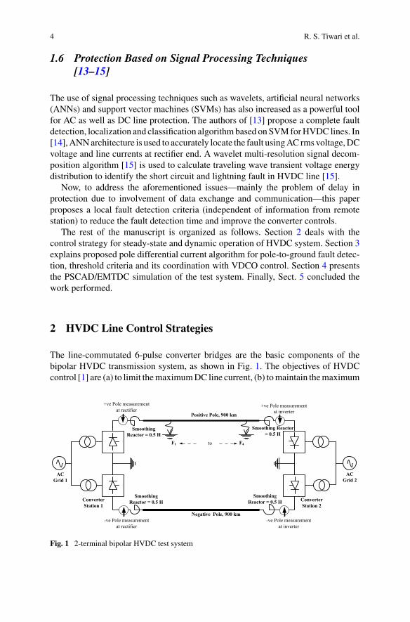
The line-commutated 6-pulse converter bridges are the basic components of thebipolar HVDC transmission system, as shown in Fig. 1. The objectives of HVDCcontrol [1] are (a) to limit themaximumDC line current, (b) tomaintain themaximum
AC Grid 1
AC Grid 2
Converter Station 1
Converter Station 2
Positive Pole, 900 km
Negative Pole, 900 km
F1 F4
Smoothing Reactor = 0.5 H
Smoothing Reactor = 0.5 H
Smoothing Reactor = 0.5 H
Smoothing Reactor = 0.5 H
+ve Pole measurementat rectifier
-ve Pole measurementat rectifier
to
-ve Pole measurementat inverter
+ve Pole measurementat inverter
Fig. 1 2-terminal bipolar HVDC test system
Ground Fault Detection Using Pole Differential … 5
Vdr
Rcr
Vdi
Rci
Vdoi cosβ
RL
Vdor cosα
Id
Vdoi cosγor
Vd
IdIdrIdiImin = 0.2 p.u.
VDCOL∆I
γi - control
- α mini in rectifier
- mini in inverter
α
Max. rectifier current limit Imax=1.2 p.u.A
B
C
D
E
F
G
H IJ
o
a
b
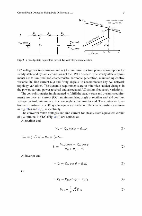
Fig. 2 a Steady-state equivalent circuit. b Controller characteristics
DC voltage for transmission and (c) to minimize reactive power consumption forsteady-state and dynamic conditions of the HVDC system. The steady-state require-ments are to limit the non-characteristic harmonic generation, maintaining controlvariable DC line current (Id) and firing angle α to accommodate any AC networktopology variations. The dynamic requirements are to minimize sudden changes inthe power, current, power reversal and associated AC system frequency variations.
The control strategies implemented to fulfill the steady-state and dynamic require-ments are constant current (CC), minimum firing angle at rectifier end and constantvoltage control, minimum extinction angle at the inverter end. The controller func-tions are illustrated via DC system equivalent and controller characteristics, as shownin Fig. 2(a) and 2(b), respectively.
The converter valve voltages and line current for steady-state equivalent circuitof a 2-terminal HVDC (Fig. 2(a)) are defined as
At rectifier end
Vdr = Vdor cosα − Rcr Id (1)
Vdor = 3π
√2VLLr, Rcr = 3
πωLcr,
Id = Vdor cosα − Vdoi cos γ
Rcr + RL − Rci(2)
At inverter end
−Vdi = Vdoi cosβ + Rci Id (3)
Or
−Vdi = Vdoi cos γ − Rci Id (4)
Vdoi = 3
π
√2VLLi (5)
6 R. S. Tiwari et al.
where VLLr, VLLi are theAC-side line-to-line voltages at rectifier and inverter stations.RL is the DC line resistance, and Rcr, Rci are the equivalent commutation resistancesof rectifier and inverter bridges. Figure 2(b) shows themodified control characteristicsABCDEandFGHIJ of rectifier and inverter stations, respectively. The details for bothare described in Tables 1 and 2 to fulfill the steady-state and dynamic requirements.
Table 1 Rectifier station requirements and control implementation
Line section Controlimplemented
Features obtained Reason
AB α-minimum Higher loading andminimized reactive powerconsumption
To enhance power flow,power factor
BC Constant current(CC)Idr(limit) = 1 P.U.
Limit maximum DC linecurrent Id (duringinverter-side voltage diprectifier operates in CC)
For valve protection
CD Voltage-dependentcurrent order limit(VDCOL)
Operates the HVDC linkwith reduced powerflowing under sudden hugevoltage dip
To maintain lower currentmargin for reduced powerflow
DE Minimum currentImin = 0.2 P.U.
To avoid zero currentthrough converter valvesdue to harmonicsgenerates HV stresses
Valve protection
Table 2 Inverter station requirements and control implementation
Point oncurve
Control implemented Features obtained Reason
IJ γ -minimum(CEA)
Provide voltage controllerat inverter, and maintainconstant voltage forsteady-state operation
Improved power factorduring operation
HI Constant β Stable operation duringheavy voltage dip atrectifier during week ACsystem interconnection
Avoided multipleoperation of controller
GH Constantcurrent (CC)
To get an intersection pointbetween rectifier andinverter characteristics, CCmust be provided atinverter
Maintain power flow inHVDC link
FG α-minimum Operates the HVDC linkwith reduced powerflowing under sudden largevoltage dip
To avoid commutationfailure during ACfaults
Ground Fault Detection Using Pole Differential … 7
The intersection point of the two characteristics shows the operating point of HVDClink.
3 Proposed Pole Differential Current Algorithm
3.1 Protection Principle
The probability of faults in the DC line is higher as compared to any other part of theHVDC system. Most of the faults in DC lines are temporary which are initiated dueto pollution or lightning strikes. Pole-to-ground fault is one of the most frequentlycaused faults due to insulation failure between line conductor and ground [16].
The traditional current differential protection algorithm has good reliability butdepends on the communication channel. Tominimize the dependency on the commu-nication channel and enhance the reliability and sensitivity, single-endmeasurement-based protection scheme is introduced. The proposed scheme uses a measurementat rectifier side using high-sensitivity GMR or Hall sensors. The measurementperformed on both poles is shown in Fig. 1. The measured samples of instanta-neous currents are used to obtain the pole differential current (PDC) as shown in (6)which is compared with the threshold, and if found greater than the said threshold,an internal fault is declared.
For normal load and external fault conditions, the PDC will be negligible. Thesudden rise in differential current guaranties the presence of an internal fault, butto enhance the security; it should be compared with a set threshold. The amplitudeof differential current gets affected by fault resistance and fault location. Still thescheme is sensitive enough for fault resistances up to 500 �.
The current measurements are performed at each station, i.e., IPR(t), INR(t), IPI(t)and INI(t). The PDC calculated at inverter and rectifier stations is given by
Pole differential current (PDC) at rectifier end IPole1(t) is given below in (6):
IPole1(t) = (IPR(t) − INR(t)) (6)
Pole differential current (PDC) at inverter end IPole2(t) is given below in (7):
IPole2(t) = (IPI(t) − INI(t)) (7)
where IPole1(t) and IPole2(t) are PDC obtained by subtracting positive and nega-tive instantaneous current samples at both stations. The pole-to-ground fault isdetected when it satisfies the criteria of (8):
IPole(t) > Ith (8)
8 R. S. Tiwari et al.
where Ith is the threshold for PDC. Whenever this criterion is satisfied—givingan indication of fault—the local or master controller was instructed for necessaryactions.
3.2 Selection of Threshold
Since the bipolar HVDC transmission system, under normal or external fault opera-tion, gives negligible PDC, so the selection of minimum threshold current increasesthe sensitivity with low fault detection time. Based on the rigorous simulation studypresented in the next section, the threshold used for identifying the fault detectiontime is set at 0.25 P.U.
3.3 Coordination of PDC and VDCOL ControlCharacteristics
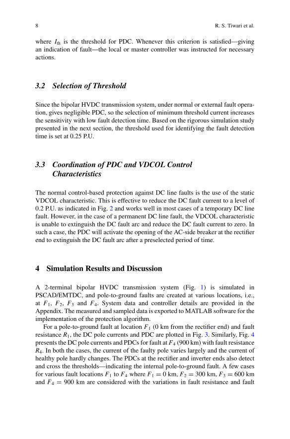
The normal control-based protection against DC line faults is the use of the staticVDCOL characteristic. This is effective to reduce the DC fault current to a level of0.2 P.U. as indicated in Fig. 2 and works well in most cases of a temporary DC linefault. However, in the case of a permanent DC line fault, the VDCOL characteristicis unable to extinguish the DC fault arc and reduce the DC fault current to zero. Insuch a case, the PDC will activate the opening of the AC-side breaker at the rectifierend to extinguish the DC fault arc after a preselected period of time.
4 Simulation Results and Discussion
A 2-terminal bipolar HVDC transmission system (Fig. 1) is simulated inPSCAD/EMTDC, and pole-to-ground faults are created at various locations, i.e.,at F1, F2, F3 and F4. System data and controller details are provided in theAppendix. The measured and sampled data is exported to MATLAB software for theimplementation of the protection algorithm.
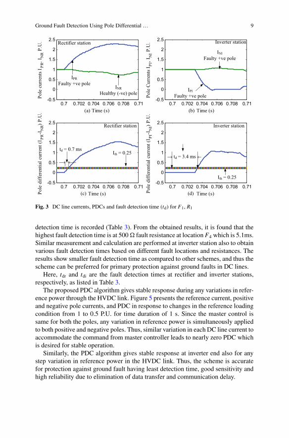
For a pole-to-ground fault at location F1 (0 km from the rectifier end) and faultresistance R1, the DC pole currents and PDC are plotted in Fig. 3. Similarly, Fig. 4presents the DC pole currents and PDCs for fault at F4 (900 km) with fault resistanceR4. In both the cases, the current of the faulty pole varies largely and the current ofhealthy pole hardly changes. The PDCs at the rectifier and inverter ends also detectand cross the thresholds—indicating the internal pole-to-ground fault. A few casesfor various fault locations F1 to F4 where F1 = 0 km, F2 = 300 km, F3 = 600 kmand F4 = 900 km are considered with the variations in fault resistance and fault
Ground Fault Detection Using Pole Differential … 9
0.7 0.702 0.704 0.706 0.708 0.71-0.5
0
0.5
1
1.5
2
2.5
(a) Time (s)
Pole
cur
rent
s IPR
, IN
R P.
U.
0.7 0.702 0.704 0.706 0.708 0.71-0.5
0
0.5
1
1.5
2
2.5
Time (s)
Pole
Cur
rent
s IPI
, IN
I P.U
.
0.7 0.702 0.704 0.706 0.708 0.71-0.5
0
0.5
1
1.5
2
2.5
Time (s)Pole
diff
eren
tial c
urre
nt (I
PR-I
NR)
P.U
.
0.7 0.702 0.704 0.706 0.708 0.71-0.5
0
0.5
1
1.5
2
2.5
Time (s)Pole
diff
eren
tial c
urre
nt (I
PI-I
NI)
P.U
.
Rectifier station Inverter station
IPRFaulty +ve pole
INRHealthy (-ve) pole
IPIFaulty +ve pole
INIFaulty +ve pole
Ith = 0.25td = 0.7 ms
Rectifier station
td = 3.4 ms
Ith = 0.25
Inverter station
(b)
(c) (d)
Fig. 3 DC line currents, PDCs and fault detection time (td) for F1, R1
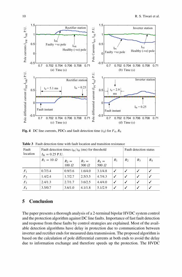
detection time is recorded (Table 3). From the obtained results, it is found that thehighest fault detection time is at 500� fault resistance at location F4 which is 5.1ms.Similar measurement and calculation are performed at inverter station also to obtainvarious fault detection times based on different fault locations and resistances. Theresults show smaller fault detection time as compared to other schemes, and thus thescheme can be preferred for primary protection against ground faults in DC lines.
Here, tdr and tdi are the fault detection times at rectifier and inverter stations,respectively, as listed in Table 3.
The proposed PDC algorithm gives stable response during any variations in refer-ence power through the HVDC link. Figure 5 presents the reference current, positiveand negative pole currents, and PDC in response to changes in the reference loadingcondition from 1 to 0.5 P.U. for time duration of 1 s. Since the master control issame for both the poles, any variation in reference power is simultaneously appliedto both positive and negative poles. Thus, similar variation in each DC line current toaccommodate the command from master controller leads to nearly zero PDC whichis desired for stable operation.
Similarly, the PDC algorithm gives stable response at inverter end also for anystep variation in reference power in the HVDC link. Thus, the scheme is accuratefor protection against ground fault having least detection time, good sensitivity andhigh reliability due to elimination of data transfer and communication delay.
10 R. S. Tiwari et al.
0.7 0.702 0.704 0.706 0.708 0.71-0.5
0
0.5
1
1.5
Time (s)
Pole
cur
rent
s IPR
, IN
R P.
U.
0.7 0.702 0.704 0.706 0.708 0.71-0.5
0
0.5
1
1.5
Time (s)
Pole
Cur
rent
s IPI
, IN
I P.U
.
0.7 0.702 0.704 0.706 0.708 0.71-0.5
0
0.5
1
Time (s)Pole
diff
eren
tial c
urre
nt (I
PR-I
NR)
P.U
.
0.7 0.702 0.704 0.706 0.708 0.71-0.5
0
0.5
1
Time (s)Pole
diff
eren
tial c
urre
nt (I
PI-I
NI)
P.U
.
INRHealthy (-ve) pole
IPRFaulty +ve pole
Ith = 0.25
IPIFaulty +ve pole
INIHealthy (-ve) pole
td = 5.1 ms td = 2.9 ms
Ith = 0.25
Rectifier station Inverter station
Rectifier station Inverter station
(a) (b)
(c) (d)
Fault instant Fault instant
Fig. 4 DC line currents, PDCs and fault detection time (td) for F4, R4
Table 3 Fault detection time with fault location and transition resistance
Faultlocation
Fault detection times tdr/tdi (ms) for thresholdIth = 0.25 P.U.
Fault detection status
R1 = 10 Ω R2 =100 Ω
R3 =300 Ω
R4 =500 Ω
R1 R2 R3 R4
F1 0.7/3.4 0.9/3.6 1.6/4.0 3.1/4.8 ✓ ✓ ✓ ✓
F2 1.4/2.4 1.7/2.7 2.5/3.5 4.7/4.3 ✓ ✓ ✓ ✓
F3 2.4/1.3 2.7/1.7 3.6/2.5 4.4/4.0 ✓ ✓ ✓ ✓
F4 3.5/0.7 3.6/1.0 4.1/1.8 5.1/2.9 ✓ ✓ ✓ ✓
5 Conclusion
The paper presents a thorough analysis of a 2-terminal bipolar HVDC system controland the protection algorithm against DC line faults. Importance of fast fault detectionand response from these faults by control strategies are explained. Most of the avail-able detection algorithms have delay in protection due to communication betweeninverter and rectifier ends for measured data transmission. The proposed algorithm isbased on the calculation of pole differential currents at both ends to avoid the delaydue to information exchange and therefore speeds up the protection. The HVDC

Ground Fault Detection Using Pole Differential … 11
0.4 0.6 0.8 1-0.5
0
0.5
1
1.5
2
Time (s)
Refe
renc
e cu
rren
t Idr
ef P
.U.
0.4 0.6 0.8 1-0.5
0
0.5
1
1.5
2
Time (s)
Posit
ive
Pole
cur
rent
I P P.
U.
0.4 0.6 0.8 1-0.5
0
0.5
1
1.5
2
Time (s)
Neg
ativ
e Po
le C
urre
nt I N
P.U
.
0.4 0.6 0.8 1-0.5
0
0.5
1
1.5
2
Time (s)
Pole
diff
eren
tial c
urre
nt (I
P-I N
) P.U
.Threshold Ith =
0.25 puPole differential current ΔIpole=0
Reference Change (Line loading) 1 to 0.5 P.U.
Change in +ve pole current 1 to
0.5 P.U.
t=0.7 s
Change in -ve pole current 1 to
0.5 P.U.
t=0.7 s
t=0.7 s t=0.8 s
Fig. 5 PDC algorithm response during change in reference power loading at rectifier end
line faults, i.e., pole-to-ground faults, were implemented with the combination ofvarious fault resistances and fault locations to observe the effect on fault detection.The simulated results show that the proposed PDC algorithms have the advantageof improved fault detection time and protection reliability and are useful as primaryprotection schemes for HVDC lines against line-to-ground short-circuit faults.
Appendix 1
Bipolar HVDC Test System
The data for the system configuration (Fig. 1) is obtained from the MATLAB model(based on a Hydro-Quebec-)mono-polar HVDC model which is modified into abipolar HVDC system. The Hydro-Quebec system was developed for steady-stateand transient analysis of a 12-pulse, 1000MW(500 kV–2kA) 50/60HzHVDC trans-mission system. The system consists of two overhead transmission line conductorsacting as forward paths for positive and negative poles and solidly grounding actingas return path. The HVDC link interconnects the two asynchronous AC grids. Thesending end of the HVDC link is connected with 500 kV, 60 Hz, and receiving end
12 R. S. Tiwari et al.
Table 4 Various parametersof converters and HVDCbipolar system
Components of HVDC system Rating and specifications
Type of HVDC link Bipolar solid grounded
Power rating 2000 MW (1000 MW eachpole)
DC voltage level ±500 kV each pole
Current rating 2 kA of each pole
Converter 1200 MVA of each pole
AC grid 1 voltage 500 kV, 60 Hz, 500 MVA
AC grid 2 voltage 345 kV, 50 Hz, 10,000 MVA
Smoothing reactor 0.5 H at both ends
AC filter 1 1200 Mvar at 60 Hz
AC filter 2 1200 Mvar at 50 Hz
AC grid is of 345 kV, 50 Hz system. The line-commutated converter bipolar HVDCtest system consists of two 6-pulse series-connected converters forming 12-pulseconverter configuration which is connected to a 900 km distributed parameter lineand smoothing reactors of 0.5 H at both ends. The various parameters of converterand HVDC bipolar system are shown in Table 4. The two 600 MVAr AC filters areconnected in the system.
Appendix 2
Current Controller and Constant Extinction Angle Control(CEA)/γ-Control
The prime objective of HVDC system control is to obtain fast and flexible powercontrol between rectifier and inverter stations under steady-state and transient opera-tion. Usually, this system operates in constant power control mode where powerorder is decided by user. Power controller derives the current order supplied toVDCOL and current controller amplifier (CCA). The α-order generated from CCAis communicated to converter firing angle control to determine valve firing instants.The converter controls at rectifier and inverter stations are set to operate in constantcurrent and constant voltage control modes, respectively; during any DC line faults,the controllers of both ends shift their operational modes from steady state so as tominimize the effect of fault on both AC–DC sides. The various converter controlmodes are current control (CC), voltage control, VDCOL, minimum alpha (CIA),gamma control (CEA), β-control modes. Figures 6, 7 and 8 present the pole control,current control and overview of control blocks of HVDC system.
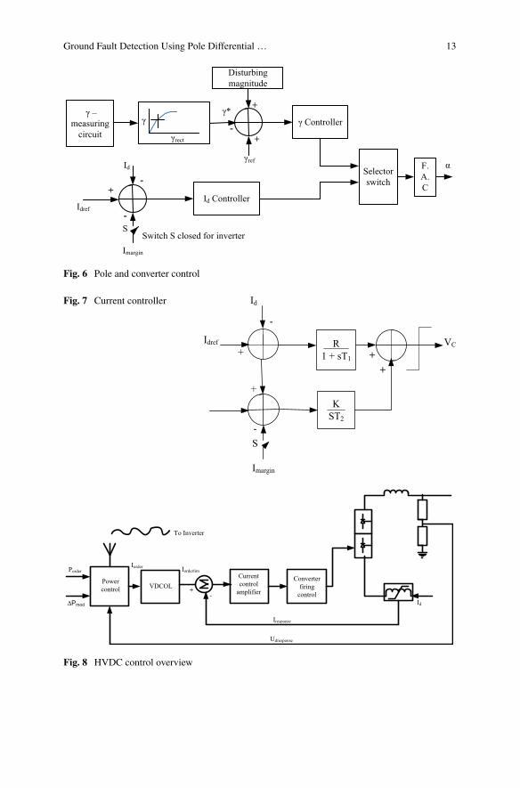
Ground Fault Detection Using Pole Differential … 13
Fig. 6 Pole and converter control
Fig. 7 Current controller
Fig. 8 HVDC control overview

14 R. S. Tiwari et al.
References
1. Sood, V.K.: HVDC transmission. In: Power Electronics Handbook, pp. 823–849. Elsevier,Amsterdam (2011)
2. Leterme, W., Jahn, I., Ruffing, P., Sharifabadi, K., Van Hertem, D.: Designing for high-voltagedc grid protection: fault clearing strategies and protection algorithms. IEEE Power EnergyMag. 17(3), 73–81 (2019). https://doi.org/10.1109/MPE.2019.2897188
3. Naidoo, D., Ijumba, N.M.: HVDC line protection for the proposed future HVDC systems. In:2004 International Conference on Power System Technology, POWERCON 2004, 2004, vol.2, pp. 1327–1332. https://doi.org/10.1109/icpst.2004.1460207
4. Ademi, S., Tzelepis, D., Dysko, A., Subramanian, S., Ha, H.: Fault current characterisationin VSC-based HVDC systems. In: IET Conference Publications, 2016, vol. 2016, no. CP671.https://doi.org/10.1049/cp.2016.0043
5. Kontos, E., Pinto, R.T., Rodrigues, S., Bauer, P.: Impact ofHVDC transmission system topologyon multiterminal DC network faults. IEEE Trans. Power Deliv. 30(2), 844–852 (2015). https://doi.org/10.1109/TPWRD.2014.2357056
6. Ouyang, Y., He, J., Hu, J., Wang, S.X.: A current sensor based on the giant magnetoresistanceeffect: design and potential smart grid applications. Sensors (Switzerland) 12(11), 15520–15541 (2012). https://doi.org/10.3390/s121115520
7. Leterme, W., Pirooz Azad, S., Van Hertem, D.: A local backup protection algorithm for HVDCgrids. IEEETrans. Power Deliv. 31(4), 1767–1775 (2016). https://doi.org/10.1109/tpwrd.2016.2543306
8. (PDF) Traveling wave fault location in power transmission systems: an overview. https://www.researchgate.net/publication/249313007_Traveling_wave_fault_location_in_power_transmission_systems_An_overview. Accessed 21 May 2020
9. Gao, B., Zhang, R., Zhang, X.: A novel procedure for protection setting in an HVDC systembased on fault quantities. J. Electr. Eng. Technol. 12(2), 513–521 (2017). https://doi.org/10.5370/JEET.2017.12.2.513
10. Qin, Y., Wen, M., Zheng, J., Bai, Y.: A novel distance protection scheme for HVDC lines basedon R-L model. Int. J. Electr. Power Energy Syst. 100, 167–177 (2018). https://doi.org/10.1016/j.ijepes.2018.02.037
11. Abu-Elanien, A.E.B., Elserougi, A.A., Abdel-Khalik, A.S., Massoud, A.M., Ahmed, S.: Adifferential protection technique formulti-terminal HVDC. Electr. Power Syst. Res. 130, 78–88(2016). https://doi.org/10.1016/j.epsr.2015.08.021
12. Suonan, J., Zhang, J., Jiao, Z., Yang, L., Song, G.: Distance protection for HVDC transmissionlines considering frequency-dependent parameters. IEEE Trans. Power Deliv. 28(2), 723–732(2013). https://doi.org/10.1109/TPWRD.2012.2232312
13. Johnson, J.M., Yadav, A.: Complete protection scheme for fault detection, classification andlocation estimation in HVDC transmission lines using support vector machines. IET Sci. Meas.Technol. 11(3), 279–287 (2017). https://doi.org/10.1049/iet-smt.2016.0244
14. Johnson, J.M., Yadav, A.: Fault location estimation in HVDC transmission line using ANN.Smart Innov. Syst. Technol. 50, 205–211 (2016). https://doi.org/10.1007/978-3-319-30933-0_22
15. Li, Z.Q., Lv, Y.P.: A novel scheme ofHVDC transmission line voltage travelingwave protectionbased on wavelet transform. In: 2008 International Conference on High Voltage Engineeringand Application, ICHVE 2008, Nov. 2008, pp. 163–167. https://doi.org/10.1109/ichve.2008.4773899
16. Khaimar, A.K., Shah, P.J.: Study of various types of faults in HVDC transmission system. In:Proceedings of the International Conference on Global Trends in Signal Processing, Informa-tion Computing and Communication ICGTSPICC 2016, no. Lcc, pp. 480–484, 2017. https://doi.org/10.1109/icgtspicc.2016.7955349
A Review on Islanding DetectionSchemes for DC Microgrids
Bhabani Kumari Choudhury and Premalata Jena
1 Introduction
Recently, renewable energy sources (RESs)-based power plants have attained sig-nificant attention because of the fast depletion of fossil fuels and global warming[1]. Distributed generations (DGs), loads, and a bidirectional converter is interfacedwith the utility grid in order to exchange powers [2]. DGs enhance the profit ofpower generation, reduce the effect of global warming, and improve power quality.Therefore, the application of DGs provides the reliability and security to the system[3, 4]. MGs are of two types, namely AC MGs and DC MGs. Operation modes ofMGs can be either isolated or grid-connected modes [5]. AC MGs research is welldeveloped because of its mature technologies, protection, and standards. Most of theDGs generate power in the form of DC, and it is converted into AC power throughDC-to-AC converter (inverter) in order to connect them with the AC MGs [6]. It isimportant to note that DC loads need DC power supply, and hence, AC power isconverted back to DC power. Here, the number of conversions, number of requiredconverters, and losses are more, so it reduces the efficiency of the system [7]. Apartfrom these, stability, synchronization, and reactive power requirement are the built-indisadvantages of AC MGs. Therefore, DC MGs are a better alternative and solutionto the above problems [8, 9]. Moreover, DC MGs are easily scalable because of theabsence of limiting equipment, such as transformers and relays.
During islanding, utility grid connection is absent. So, DGs are the main sourcesat this time. But, the power can reach to the consumers without any interruptionduring islanding due to DGs [10]. Here, employees can be affected by islanding as
B. K. Choudhury (B) · P. JenaDepartment of Electrical Engineering Indian Instituteof Technology Roorkee, Roorkee 247667, Indiae-mail: [email protected]
P. Jenae-mail: [email protected]
© The Editor(s) (if applicable) and The Author(s), under exclusive licenseto Springer Nature Singapore Pte Ltd. 2021O. H. Gupta and V. K. Sood (eds.), Recent Advances in Power Systems, Lecture Notesin Electrical Engineering 699, https://doi.org/10.1007/978-981-15-7994-3_2
15
16 B. K. Choudhury and P. Jena
they may not notice that some part of the circuit is working, which may stop re-connection of devices automatically [11]. In order to maintain stability, it is essentialto maintain a balance between load and generation in the islanded circuit. The above-stated reasons can be avoided by rapidly detecting the islanding, so that it can bedisconnected from the primary circuit as quickly as possible. This process is knownas anti-islanding [12]. The requirements for IDSs in DGs are outlined in [13], whichclearly indicates that DGs should disconnect from the grid within 2 s. Otherwise,it will draw a significantly high amount of current to keep the balance. Due to this,DGs are damaged.
In [14–17], some AC MGs islanding is reported. However, DC MG IDSs are inthe initial stage and not rigorously studied in the literature. This paper presents anoverview of islanding detection schemes, which is used for DC MGs. The require-ments of DC MGs IDSs along with their advantages over the AC MGs IDSs arereported. Recent research and developments in this field are presented with possiblechallenges, and classification of the same is highlighted.
The rest of the paper is organized as follows. DCMGs IDSs and their advantagesand disadvantages are presented in Sect. 2. Different types of passive IDSs for DCMGs are explained in Sect. 3, and active IDSs concepts and its types are reported inSect. 4. At last, final conclusions are drawn in Sect. 5 with some future insights.
2 DC MGs Islanding Detection Schemes
Islanding detection methods which detect the islanding situation with fewer falsepositives is the leading research area.When the electrical systemparameters crosses acertain threshold value, a trip signal is generated.Here, tripping time is the timewhichis required to successfully separate the two systems during islanding as reported in[18]. No fuse circuit breakers and solid-state circuit breakers are commonly usedcircuit breakers in DC MGs [19]. The author in [20] mentioned that in DC MGs,the detection time is with in 0.2 s. The advantages and disadvantages of DC and ACMGs IDSs are given in Table 1.
2.1 Intentional/Planned IDSs
Intentional/Planned IDSs are a detection method where generation and loads arescheduled prior to islanding. It means that which parts of the load to be isolated isdecided before islanding [21, 22]. This type of detection technique is applicable toAC MGs as well as DC MGs. The leading cause of this type of islanding detectionis a preplanned switching event. During such cases, the number of transients is lessin MGs.

A Review on Islanding Detection Schemes for DC Microgrids 17
Table 1 Comparison between AC MG and DC MG IDSs
Parameters AC MGs IDSs DC MGs IDSs
Standards Available (IEEE 1547) Not available (RequiredReconsideration)
System Parameters Voltage, current, impedance,Active power, reactive power,frequency, harmonics, andphase
Voltage, current, activepower, and impedance
IDSs available Passive, active, and hybrid Passive and active
Complexity Easier than DC MG IDSs Complex
Accuracy Less accurate Accurate
Tripping time Less than 0.5 s Less than 0.2 s
2.2 Unintentional/Unplanned IDSs
Unintentional/Unplanned IDSs are a detection method that is uncertain in nature.The leading cause of these type of IDSs is unplanned switching events [23, 24].Islanding detection should be quick in order to maintain the reliability and stabilityof MGs, with a proper control strategy. In this case, the severity of the transientsis more. During islanding conditions, electrical characteristics like current, voltage,impedance, frequency, active, reactive power output, etc., of DGs are changed signif-icantly. In order to detect islanding, it is essential to observe the electrical parametersof the system continuously. IDSs are of two types, namely remote IDSs and localIDSs. The detailed classification is shown in Fig. 1.
Remote IDSsThe communicationmedium between the grids and the DGs ofMGs isrequired in this type of IDSs. Due to this, the cost of the islanding circuit increases,which is the major challenge of this type of IDSs. The examples of these IDSs,which are applicable for DC MGs are transfer trip, impedance insertion, and powerline carrier communication (PLCC) IDSs. In transfer trip IDSs, supervisory controland data acquisition (SCADA) are used to monitor the status of circuit breakers andreclosures, which are present near to the point of common coupling (PCC) [25]. Inthe impedance insertion method, a low-value impedance is inserted nearer to thePCC in order to obtain proper power balance between generations and load [26]. Inthe PLCC method, a low energy signal transmits from the transmitter (utility side)to the receiver (DGs side). The disappearance of the signal represents the islandingcondition [17]. Remote IDSs are more accurate and reliable than local detectionschemes, but these are uneconomical because of their communication equipment.
Local IDSs Local IDSs utilize measurement and monitoring of electrical parameterslike impedance, voltage, active power, etc., on the DGs side. The detailed classifica-tion of local IDSs is represented in Fig. 1.

18 B. K. Choudhury and P. Jena
IDSs for DC Microgrids
RemoteIDS
• PLCC• Impedance Insertion• Transfer Trip
LocalIDS
PassiveIDS
• Under/Over Voltage (UOV)• Rate of Change of Power(ROCOP)• Rate of Change of Voltage(ROCOV) and Rate of Changeof Current (ROCOC)• Change in Impedance
ActiveIDS
• Impedance Measurement• Positive Feedback Injection
Fig. 1 Classification of DC MGs IDSs
3 Passive IDSs for DC MGs
Passive IDSsmonitor the electrical systemparameters like voltage, impedance, activeand reactive power, frequency of DGs, etc., to identify the islanding. In DC MGs,the system parameters are voltage, impedance, and active power output of DGs.The islanding situation can be identified when the system parameters deviate from apredefined threshold value. In [27], passive IDSs for DC MGs have been explained.Note that, the implementation of passive detection schemes is simple and easy. Non-detection zone (NDZ) is the major challenge of this IDSs [28]. However, suitablethreshold selection is also a complicated and challenging task.
3.1 Under/Over-Voltage-Based IDSs
In this type of IDS, it is required to sample the voltage v periodically and monitorto detect sudden changes in voltage in order to detect a fault condition. UOV IDS isimportant for grid-interfaced converters as the primary function of this type of con-verters is to maintain proper balance. A sudden change in voltage occurs commonlyin the grid due to frequent removal and attachment of loads, so a threshold needs to beset to avoid faults [29]. The IDSs calculate the change in terminal voltage of DC/DCconverter with t window length. Then, the obtained signal is compared continuously.


![Pay Scales Er SK Sood[1]](https://static.documents.pub/doc/80x56/5469cc6aaf7959637e8b4b2e/pay-scales-er-sk-sood1.jpg)