88
The updated F3SJ is even easier to use. F3SJ Ver. 2 Safety Light Curtain (Type 4) The red lines in the photo that indicate the light beams are not actually visible.

The updated F3SJ is even easierto use.
F3SJ Ver. 2Safety Light Curtain (Type 4)
Cat. No. F074-E1-04
Authorized Distributor:
Note: Specifications subject to change without notice.
OMRON CorporationIndustrial Automation CompanySafety Devices DivisionShiokoji Horikawa, Shimogyo-ku,Kyoto, 600-8530 JapanTel: (81)75-344-7119/Fax: (81)75-344-7149
Regional Headquarters
OMRON EUROPE B.V.Wegalaan 67-69, NL-2132 JD HoofddorpThe NetherlandsTel: (31)2356-81-300/Fax: (31)2356-81-388
OMRON ELECTRONICS LLC1 East Commerce Drive, Schaumburg, IL 60173U.S.A.Tel: (1)847-843-7900/Fax: (1)847-843-8568
OMRON ASIA PACIFIC PTE. LTD.83 Clemenceau Avenue,#11-01, UE Square,239920 SingaporeTel: (65)6835-3011/Fax: (65)6835-2711
OMRON (CHINA) CO., LTD.Room 2211, Bank of China Tower,200 Yin Cheng Road (M),Shanghai, 200120 ChinaTel: (86)21-5037-2222/Fax: (86)21-5037-2200
Printed in Japan0306-3M (0605) (H)
The red lines in thephoto that indicatethe light beams arenot actually visible.
Setting Console
"SD Manager" PC Setting Support Software
Beam alignment is easier.
Ver. 2 Label Color
The ambient incident light intensity can be checked. The error log can be displayed.
The "SD Manager" PC Setting Support Software helps reduce the time required for installing and troubleshooting the Safety Light Curtain.
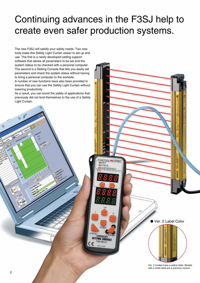
Continuing advances in the F3SJ help tocreate even safer production systems.
The new F3SJ will satisfy your safety needs. Two newtools make this Safety Light Curtain easier to set up anduse. The first is a newly developed setting supportsoftware that allows all parameters to be set and thesystem status to be checked with a personal computer.The second is a Setting Console that lets you easily setparameters and check the system status without havingto bring a personal computer to the worksite.A number of new functions have also been provided toensure that you can use the Safety Light Curtain withoutlowering productivity.As a result, you can boost the safety of applications thatpreviously did not lend themselves to the use of a SafetyLight Curtain.
Choose from two new tools for setting parametersand checking the system status.Choose from two new tools for setting parametersand checking the system status.
All parameters can be set and the system statuscan be checked with a personal computer. Inaddition to making it easy to monitor the beamalignment, the ambient incident light intensitycan be displayed in bar graph form for an easycheck of the system status.
F39-GWUM "SDManager" PC SettingSupport Software
The incident light level can be displayedin a bar graph for each beam.
The incident light level when the lightemission of the Safety Light Curtain isstopped is displayed in a bar graph.
The cause of the errors andcountermeasures are both displayed.
When you don't want to carry apersonal computer onto theworksite, the Setting Console is ahandy way to set parameters andcheck the system status.
Note: The range of parameter setting and system statuschecking capabilities is different for the PC SettingSupport Software and the Setting Console.
2 3
Connection Cable
To a USB terminal
F39-MC21Setting Console for the F3SJ
BranchConnector
F3SJ
BranchConnector
F3SJ
Ver. 2 models have a yellow label. Modelswith a white label are a previous version.
F39-JC@A Single-end Connector Ca-ble or F39-JC@BDouble-end Con-nector Cable
F39-JC@A Single-end Connector Ca-ble or F39-JC@BDouble-end Con-nector Cable

Setting Console
"SD Manager" PC Setting Support Software
Beam alignment is easier.
Ver. 2 Label Color
The ambient incident light intensity can be checked. The error log can be displayed.
The "SD Manager" PC Setting Support Software helps reduce the time required for installing and troubleshooting the Safety Light Curtain.
Continuing advances in the F3SJ help tocreate even safer production systems.
The new F3SJ will satisfy your safety needs. Two newtools make this Safety Light Curtain easier to set up anduse. The first is a newly developed setting supportsoftware that allows all parameters to be set and thesystem status to be checked with a personal computer.The second is a Setting Console that lets you easily setparameters and check the system status without havingto bring a personal computer to the worksite.A number of new functions have also been provided toensure that you can use the Safety Light Curtain withoutlowering productivity.As a result, you can boost the safety of applications thatpreviously did not lend themselves to the use of a SafetyLight Curtain.
Choose from two new tools for setting parametersand checking the system status.Choose from two new tools for setting parametersand checking the system status.
All parameters can be set and the system statuscan be checked with a personal computer. Inaddition to making it easy to monitor the beamalignment, the ambient incident light intensitycan be displayed in bar graph form for an easycheck of the system status.
F39-GWUM "SDManager" PC SettingSupport Software
The incident light level can be displayedin a bar graph for each beam.
The incident light level when the lightemission of the Safety Light Curtain isstopped is displayed in a bar graph.
The cause of the errors andcountermeasures are both displayed.
When you don't want to carry apersonal computer onto theworksite, the Setting Console is ahandy way to set parameters andcheck the system status.
Note: The range of parameter setting and system statuschecking capabilities is different for the PC SettingSupport Software and the Setting Console.
2 3
Connection Cable
To a USB terminal
F39-MC21Setting Console for the F3SJ
BranchConnector
F3SJ
BranchConnector
F3SJ
Ver. 2 models have a yellow label. Modelswith a white label are a previous version.
F39-JC@A Single-end Connector Ca-ble or F39-JC@BDouble-end Con-nector Cable
F39-JC@A Single-end Connector Ca-ble or F39-JC@BDouble-end Con-nector Cable
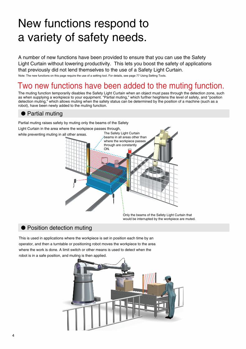
New functions respond toa variety of safety needs.
Partial muting
Warning zone
Detection zone
Warning zone
Detection zone
A number of new functions have been provided to ensure that you can use the SafetyLight Curtain without lowering productivity. This lets you boost the safety of applicationsthat previously did not lend themselves to the use of a Safety Light Curtain.Note: The new functions on this page require the use of a setting tool. For details, see page 77 Using Setting Tools.
Two new functions have been added to the muting function.The muting function temporarily disables the Safety Light Curtain when an object must pass through the detection zone, suchas when supplying a workpiece to your equipment. "Partial muting," which further heightens the level of safety, and "positiondetection muting," which allows muting when the safety status can be determined by the position of a machine (such as arobot), have been newly added to the muting function.
Partial muting raises safety by muting only the beams of the Safety
Light Curtain in the area where the workpiece passes through,
while preventing muting in all other areas. The Safety Light Curtainbeams in all areas other thanwhere the workpiece passesthrough are constantlyON.
Only the beams of the Safety Light Curtain thatwould be interrupted by the workpiece are muted.
Position detection muting
This is used in applications where the workpiece is set in position each time by an
operator, and then a turntable or positioning robot moves the workpiece to the area
where the work is done. A limit switch or other means is used to detect when the
robot is in a safe position, and muting is then applied.
Fixed blanking
The blanking function disables specific beams of the Safety Light Curtain.When a part of a machine is located inside the detection zone of the Safety Light Curtain,the safety output will normally remain OFF and the machine cannot operate. The blankingfunction makes it possible to disable specific beams for applications such as this.
Floating blanking
Dividing the zone between series-connected sensors
A warning zone can be set to alert people before they enter a danger zone.For example, you can set the F3SJ to generate only an alarm when someone approaches the danger zone, and to turn OFFthe control output when someone actually enters the danger zone. You can also divide the detection zone for a single F3SJinto two zones, or set a warning zone for multiple, series-connected F3SJ Units. Plus, the auxiliary output can be used toactivate a flashing lamp as a warning to alert the person before turning OFF the machinery.
A single sensor can also be divided
The beam that would otherwise beconstantly interrupted by theworkbench is disabled.
In this case, 2-beam floatingblanking is set. If three or morebeams are interrupted, theoutput goes OFF.
4 5

Easier to install,easier to use.
Selecting a device is as easy as 1-2-3.
The direction of all screws canbe oriented perpendicular tothe lens surface. Easy screw-driver access.
30 mm
15 mm
24 mm
45 mm 26 mm
2 mm
Previous model F3SJ
Previous model
10 mm
37 mm
Can be used with a pitch of 18 to 20 mm
6 mm
F3SJ
Hand/limb/body-protection Detection
245 mmMinimum
2495 mmMaximum
F3SJ-A
Protective height(0245 to 2495 mm) Output type Detection type
14 Finger
20 Hand
30 Hand/limb/body
P
N
PNPoutput
NPNoutput
Sensor length = Protective height
Hand-protectionDetection
6 7
Select the required sensor length.The F3SJ incorporates the "perfect fit" concept that is afeature of OMRON's other Safety Light Curtains. With a line-up of products in 1-beam increments, you can find thesensor that fits your setup perfectly. Refer to the list ofsensor models on pages 10 and 11 to select the minimumsensor length required to cover the area you want to protect.
Note: We can also manufacture sensors with lengths not included in the listof models. For details, please consult your OMRON salesrepresentative.
Select the output transistor.Choose the PNP type when installing in safety systemconfigurations that comply with the Machinery Directive orwhen using with a dedicated controller (F3SP-B1P or F3SX).NPN types are also available as standard products whenreplacing existing area sensors.
Select the application.With three types of sensors available, you can select theideal type to best support your application. Choose fromthe finger protection model, hand protection model, orhand/limb/body protection model.For areas where there is only a short distance to thesource of danger, select the finger protection model. Forareas where there is some distance to the hazardous point,and where the machinery stops with sufficient time tospare, choose the economical hand/limb/body protectionmodel.Note: After selecting the type of device, calculate the safety distance
described on page 74 and change your selection if necessary.
Finger-protectionDetection
Capability: 14 mm diameter(Beam gap: 9 mm)
Capability: 20 mmdiameter(Beam gap: 15 mm)
Capability: 30 mmdiameter(Beam gap: 25 mm)
The thin sensor saves valuable space.The sensor is 6 mm thinner than our previous models. Whenyou include the newly designed mounting brackets, whichalso enable beams to be aligned after the sensor is mounted,the total thickness is 26 mm - a reduction of 19 mm comparedto previous models. The low profile means the sensor will notget in the way when adding safety applications to existingequipment.
Flexible cable with a 5 mm bendingradius makes wiring a snap.The F3SJ cables (0.3 m) have M12 connectors and can berouted in any direction. Problems with connectorcompatibility have been eliminated.
The included standard mountingbrackets are easier than ever to use.The included mounting brackets, which are suitable for generaluse, have been redesigned with ease of use in mind. The newdesign allows easy screwdriver access, even when mounting intight spaces.Also, after aligning the beams, screws can be tightened whileoriented perpendicular to the lens surface, just like the panelmounting screws. On previous models, the carefully adjustedbeam angles would sometimes come out of alignment whentightening the final screws. This problem has been solved withthe F3SJ, because the screw-tightening direction is differentfrom the angle adjustment direction. The result is reducedinstallation time.
Free-directional cables can berouted down, back, left or right.
Flexible cables with 5 mmbending radius can beadhesively mounted to thefloor.
The sensor can be rotated alongits axis. Beam alignment can befine-tuned, even when mountedside by side on a surface.
Side-mounting in tight spaces is simple.When using standard mounting brackets to mount a sensoron its side, the bracket protrudes outward in front of the lenssurface. When this protrusion is of concern, use the F39-LJ2side-mounting brackets (sold separately).
Easy to change from previous models.When replacing your previous standard multiple-beam areasensor, use the F39-LJ4 top / bottom mounting bracket B(sold separately), which features enlarged mounting holes.
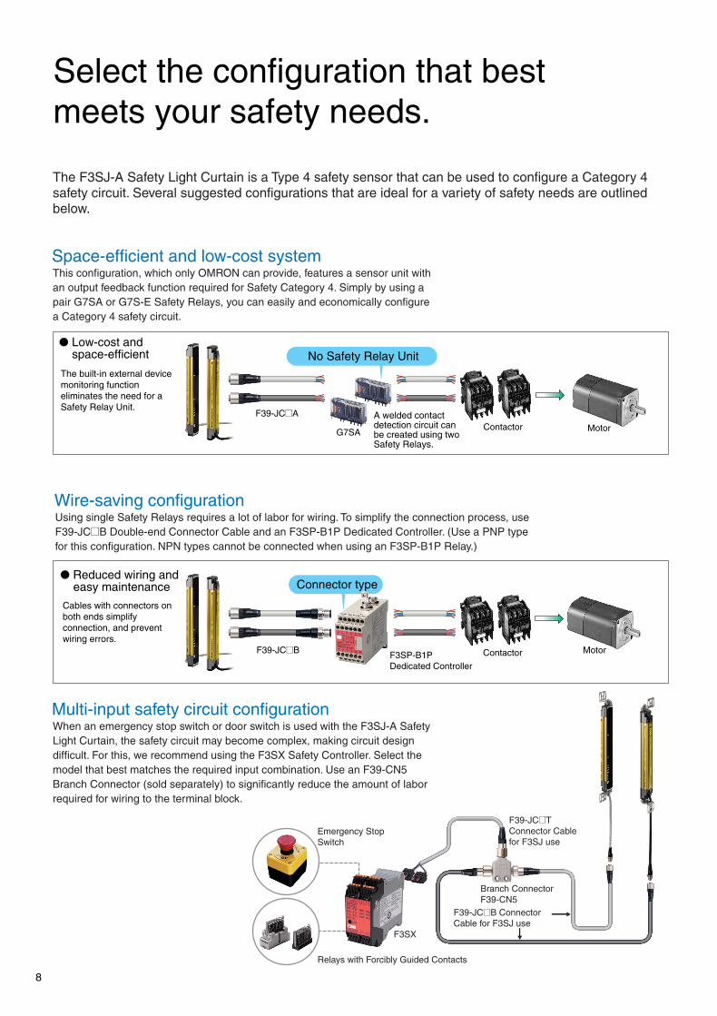
Select the configuration that bestmeets your safety needs.
A G V
Application exampleU-shaped configuration
F39-LJ3 free-location mountingbrackets can be mounted in anylocation, without getting in theway of the adjacent sensor.
Total length: Approx. 10 m (400 beams)Approx. 2.5 m (100 beams)
20 mm gap between end beams whenconnected side by side
25 mm
Series connection cable up to 15 m long
25 mm
25 mm
25 mm
A variety of featuresare provided for easier use.
8 9
Emergency StopSwitch
F39-JC@B ConnectorCable for F3SJ use
Branch ConnectorF39-CN5
F39-JC@TConnector Cablefor F3SJ use
F3SX
Relays with Forcibly Guided Contacts
This configuration, which only OMRON can provide, features a sensor unit withan output feedback function required for Safety Category 4. Simply by using apair G7SA or G7S-E Safety Relays, you can easily and economically configurea Category 4 safety circuit.
The F3SJ-A Safety Light Curtain is a Type 4 safety sensor that can be used to configure a Category 4safety circuit. Several suggested configurations that are ideal for a variety of safety needs are outlinedbelow.
F39-JC@A
G7SAContactor Motor
No Safety Relay Unit
F3SP-B1PDedicated Controller
Connector type
F39-JC@B Contactor Motor
Space-efficient and low-cost system
Low-cost andspace-efficient
The built-in external devicemonitoring functioneliminates the need for aSafety Relay Unit.
A welded contactdetection circuit canbe created using twoSafety Relays.
Using single Safety Relays requires a lot of labor for wiring. To simplify the connection process, useF39-JC@B Double-end Connector Cable and an F3SP-B1P Dedicated Controller. (Use a PNP typefor this configuration. NPN types cannot be connected when using an F3SP-B1P Relay.)
Wire-saving configuration
Reduced wiring andeasy maintenance
Cables with connectors onboth ends simplifyconnection, and preventwiring errors.
When an emergency stop switch or door switch is used with the F3SJ-A SafetyLight Curtain, the safety circuit may become complex, making circuit designdifficult. For this, we recommend using the F3SX Safety Controller. Select themodel that best matches the required input combination. Use an F39-CN5Branch Connector (sold separately) to significantly reduce the amount of laborrequired for wiring to the terminal block.
Multi-input safety circuit configuration
OMRON has developed a unique interference light prevention algorithm thatautomatically prevents malfunction, even when light is received from three sets.This feature is ideal for applicationswhere it is not possible to perform wiringwith an interference sensor, such asbetween an AGV and installed equipment.Also, the Setting Tool can be used toadjust the emitted light intensity tominimize the effect of light on otherdevices.(Updated function)
Resistant to mutual interference. No wiring betweensensors and no interference for up to three sets.
Sensors with protective heights of up to nearly 2.5 meters are available forapplications that involve large-sized workpieces. And if you happen to make changesin the future, you can always extend the protective height with series connections. Upto four sets, or 400 beams, can be series-connected, and with series connectioncables up to 15 meters in length, applications can cover a wide area.
Maximum protective height of 2,495 mm.Series connection is more convenient than ever.
To create "perfect fit" installations with no dead zones or extra space whenmaking series connections in L- or U-shaped configurations, use the F39-LJ3 free-location mounting brackets (sold separately) and F39-JJR06L orF39-JJR15L Side-by-side Series Connection Cable.
No bottlenecks in workflow. Free-location bracketsmake vertical installation easy.
Side-by-side SeriesConnection Cable(F39-JJR06L)
Keep a 25-mm beam gap in L-shaped installations.The cable (F39-JJR06L) does not get in the waywhen used in series connections.

The newly developed board-free "1-bit module" is freely mounted on flat
cable.In addition to our standard products, we
are now able to manufacture devices with adifferent number of beams, or with a variety of
beam gaps. For details about these specialproducts, consult your OMRON sales representative.
Lens
Holder cap
Holder
Shield plate
IC package
Can also be used with equipment subject to US OSHA standards (29 CFR 1910.212).Satisfies the requirements of the ANSI/RIA R15.06-1999 standards for industrial robots.
International standards
EU legislation EN standards
JIS standards
North American standards
IEC61496-1, IEC61496-2, IEC61508 1998 (SIL3)
Machinery Directive, EMC Directive, EN61496-1, prEN61496-2, EN61508 2001 (SIL3)
JIS B9704-1, B9704-2
UL61496-1, UL61496-2, UL508, UL1998, CAN/CSA22.2 NO.14, CAN/CSA22.2 NO.0.8
cULus
Built-in muting function
No controller required. Simply attach the Key Cap (sold separately) tothe sensor.
F39-CN6Key Cap for Muting
The muting function temporarily disables the light curtainwhen an object must pass through the detection zone, suchas when supplying a workpiece to your equipment.In the past, this function required a dedicated mutingcontroller, but now it is built into the F3SJ. To use the mutingfunction, purchase the F39-CN6 Key Cap for Muting (soldseparately). The muting function is enabled simply byreplacing the Unit's cap with this Key Cap. In addition, amuting sensor that determines the muting timing, as well asa muting lamp that communicates the muting status to otheroperators, should be connected to the F3SJ.
1 2 3 4 5 Incident light level
170% or higher of control output ON level
From 130 to 170% of control output ON level
From 100 to 130% of control output ON level
From 75 to 100% of control output ON level
From 50 to 75% of control output ON level
Less than 50% of control output ON level
A B C Cause of error
OFF Blinking ON
OFF ON
Error Mode Indication Patterns and Causes of Errors
Indication Patterns and Light Levels of the Incident Light Level Indicator
ERROR-C
ERROR-B
ERROR-A
LEVEL-1
LEVEL-2
LEVEL-3
LEVEL-4
LEVEL-5
Emitter Receiver
Mutual interference or ambient incident light.Power supply voltage of F3SJ is out of the rated range.Insufficient current capacity of power supply.
Incident light to blanking beams.
Failure in communication line.Emitter and receiver have different F3SJ typenames or number of series connections.
Outside the effective range of parameters set by setting tool.
Cap is not attached.
External device monitor failure.
Failure in interlock selection input line or reset input line.
Muting wiring failure.
Failure in control output wiring.
Failure in series connection cable wiring.
Broken series connection cable.
Influence of electrical noise, or failure in a series-connected F3SJ.
Wiring error or broken communications wire.
Failure in wiring of external display lamp output.
Failure in wiring of auxiliary output.
10 11
New functions for extra reliability.
Combine safety and productivity with acontroller-less muting function.
The incident light level indicator uses orange LED lights forlevels 1 to 3, and green LED lights for levels 4 to 5. Thegreen LED lights indicate that a stable amount of light isbeing received. The error indicator uses a variety ofillumination and blinking patterns, enabling more detaileddiagnosis results to be communicated via the display.
A new and improved LED indicator.
The Safety Light Curtain can be disabled whenan AGV carrying a workpiece passes through.
The connectors for series connection feature an intelligentdesign. To connect a series connection cable to the F3SJ,remove the Key Cap that is required when the sensor is used byitself. If you should happen to forget to connect the seriesconnection cable, the sensor will not operate by itself without theKey Cap. This solves the problem of sensors operatingindependently when a series connection cable is accidentally leftunconnected, such as when equipment is moved.
A measure to prevent you from forgettingto connect a series connection cable.
Like previous Type 4 Safety Light Curtains, the F3SJ conforms to the latestrequired safety standards and regulations. Since the F3SJ also complies withIEC61508, the international standard for functional safety, safety is ensuredregardless of where it is used.
Complies with the latest international safety standards and regulations.
Operates as a singlesensor when the KeyCap is attached.
Does not operatewithout the Key Cap.
The quality of Safety Light Curtain performance is determinedby the quality of the emitter/receiver elements. With previousmodels, one faulty beam resulted in the malfunction of theentire sensor. However, the F3SJ features a newly developed
"1-bit module" that integrates the lens and other optical partswith the emitter IC and receiver IC, which are key devices.With characteristic inspection performed on each beam, aswell as a thorough quality traceability system using 2D codes,performance is assured.
New core technology that supports reliability and customizability.
30 dia. 30 dia.
Safety Light Curtain (Type 4) F3SJ12
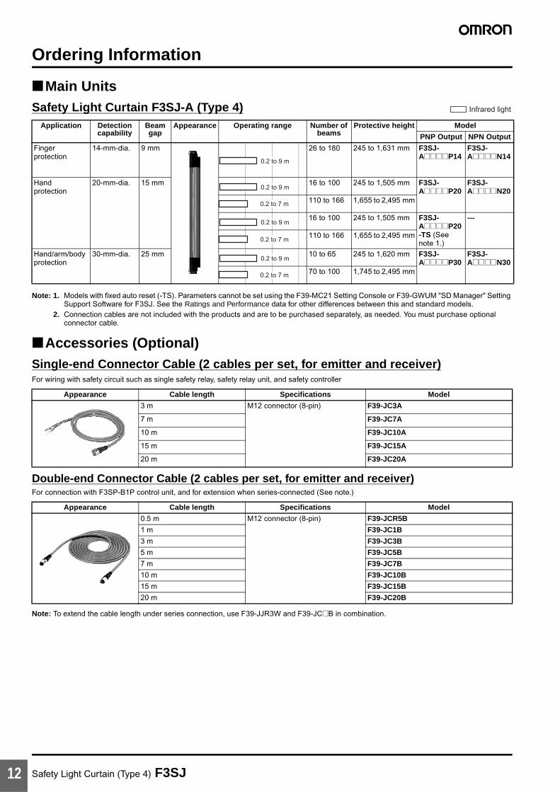
Ordering Information
Main UnitsSafety Light Curtain F3SJ-A (Type 4)
Note: 1. Models with fixed auto reset (-TS). Parameters cannot be set using the F39-MC21 Setting Console or F39-GWUM "SD Manager" Setting Support Software for F3SJ. See the Ratings and Performance data for other differences between this and standard models.
2. Connection cables are not included with the products and are to be purchased separately, as needed. You must purchase optional connector cable.
Accessories (Optional)Single-end Connector Cable (2 cables per set, for emitter and receiver)For wiring with safety circuit such as single safety relay, safety relay unit, and safety controller
Double-end Connector Cable (2 cables per set, for emitter and receiver)For connection with F3SP-B1P control unit, and for extension when series-connected (See note.)
Note: To extend the cable length under series connection, use F39-JJR3W and F39-JC@B in combination.
Application Detection capability
Beam gap
Appearance Operating range Number of beams
Protective height Model
PNP Output NPN Output
Fingerprotection
14-mm-dia. 9 mm 26 to 180 245 to 1,631 mm F3SJ-A@@@@P14
F3SJ-A@@@@N14
Handprotection
20-mm-dia. 15 mm 16 to 100 245 to 1,505 mm F3SJ-A@@@@P20
F3SJ-A@@@@N20
110 to 166 1,655 to 2,495 mm
16 to 100 245 to 1,505 mm F3SJ-A@@@@P20-TS (See note 1.)
---
110 to 166 1,655 to 2,495 mm
Hand/arm/bodyprotection
30-mm-dia. 25 mm 10 to 65 245 to 1,620 mm F3SJ-A@@@@P30
F3SJ-A@@@@N30
70 to 100 1,745 to 2,495 mm
Infrared light
0.2 to 9 m
0.2 to 9 m
0.2 to 7 m
0.2 to 9 m
0.2 to 7 m
0.2 to 9 m
0.2 to 7 m
Appearance Cable length Specifications Model
3 m M12 connector (8-pin) F39-JC3A
7 m F39-JC7A
10 m F39-JC10A
15 m F39-JC15A
20 m F39-JC20A
Appearance Cable length Specifications Model
0.5 m M12 connector (8-pin) F39-JCR5B
1 m F39-JC1B
3 m F39-JC3B
5 m F39-JC5B
7 m F39-JC7B
10 m F39-JC10B
15 m F39-JC15B
20 m F39-JC20B

Safety Light Curtain (Type 4) F3SJ 13
Power Cable (Included with the main unit) (2 cables per set, for emitter and receiver)
Series Connection Cable (2 cables per set, for emitter and receiver)
Note: 1. Total cable length of series connection is 0.6 m to connect to connector cable of the main sensor unit.For series connection with minimum length, use the F39-JJR06L or F39-JJR15L.
2. When using the F39-EJ@@@@-L/D Water-resistant Case in series connection configurations, use the special series connection cables for the Water-resistant Case. Refer to page 18 for details.
Safety Controller (Dedicated PNP output type) (See note.)
Note: F3SJ for NPN output type cannot be connected.
Connection Cable for F3SX (F3SX↔F39-CN5)
Branch Connector for F3SX (F39-JC@T↔F39-JC@B)
Appearance Cable length Model
0.3 m F39-JJR3K
Type Appearance Cable length Model Application
Series connection cable 0.3 m F39-JJR3W For series connection (See note 1.)When using the Water-resistant Case. (See note 2.)
Extension cable 0.5 to 15 m F39-JC@B To change series connection length in combination with F39-JJR3W
Side-by-side Series connection cable
0.06 m F39-JJR06L Dedicated series connection cable with minimum length, used in place of the sensor's cable with connector0.15 m F39-JJR15L
Type Appearance Specifications Model Remarks
F3SX Safety Controller (See note.)
• Can connect 2 sets of F3SJs and emergency stop switch
• DC semiconductor safety output
F3SX-EL2 For other models and functions, refer to the Safety Components Series catalog (Cat. No. Y106).
• Can connect 4 sets of F3SJs and emergency stop switch
• DC semiconductor safety output
F3SX-E-L2L2
• Can connect 2 sets of F3SJs and emergency stop switch
• Relay output (2NO+1NC)
F3SX-N-L2R
• Can connect 4 sets of F3SJs and emergency stop switch
• Relay output (2NO+1NC)
F3SX-N-L2L2R
Appearance Cable length Model
1 m F39-JC1T
3 m F39-JC3T
5 m F39-JC5T
7 m F39-JC7T
10 m F39-JC10T
15 m F39-JC15T
Appearance Model
F39-CN5

Safety Light Curtain (Type 4) F3SJ14
Accessory connection example
Relays with Forcibly Guided Contacts
Control unit (Can not be used as a muting system)(Dedicated PNP output type) (See note.)
Note: F3SJ for NPN output type cannot be connected.
Type Appearance Specifications Model Remarks
G7SA Relays with Forcibly Guided Contacts
• No. of contacts: 4• Contact type: 2NO+2NC• Rated switch load: 250 VAC 6 A, 30 VDC 6 A
G7SA-2A2B For other models and functions, refer to the local catalog or website.
• No. of contacts: 4• Contact type: 3NO+1NC• Rated switch load: 250 VAC 6 A, 30 VDC 6 A
G7SA-3A1B
G7S@-E Relays with Forcibly Guided Contacts
• No. of contacts: 6• Contact type: 4NO+2NC• Rated switch load: 250 VAC 10 A, 30 VDC 10 A
G7S-4A2B-E
• No. of contacts: 6• Contact type: 3NO+3NC• Rated switch load: 250 VAC 10 A, 30 VDC 10 A
G7S-3A3B-E
Appearance Output Model Remarks
Relay, 3NO+1NC F3SP-B1P (See note.) For connection with F3SJ-A, use an F39-JC@B double-end connector cable
F3SJEmitter
Branch connector forsafety light curtains
F39-CN5
Double-end connector cable:F39-JC@B-L (gray)
Wire color: Gray
Wire color: Black
Double-end connector cableF39-JC@B-D (black)
Connection cable for F3SXF39-JC@T
F3SX
F3SJReceiver
Gray Black

Safety Light Curtain (Type 4) F3SJ 15
Dedicated External Indicator Set (Can be connected to either an emitter or a receiver)
Note: For indication timing (operation mode) see "Ratings and Performance" on page 20.
General External Indicator Cable
Spatter Protection Cover (Includes two pieces for emitter and receiver) (Each unit reduces the operating range by 10%)
Note: The same 4-digit numbers as the protective heights (@@@@ in the light curtain type names) are substituted by @@@@ in the model names.
Appearance Color Model Remarks
Red F39-A01PR-PAC Indicator (red), mounting bracket (1 set), and dedicated connection cable (0.1 m)
Green F39-A01PG-PAC Indicator (green), mounting bracket (1 set), and dedicatedconnection cable (0.1 m)
Yellow F39-A01PY-PAC Indicator (yellow), mounting bracket (1 set), and dedicated connection cable (0.1 m)
Appearance Cable length Specifications Model
3 m Cable to connect top of the main unit and an off-the shelf external indicator (2-wire)
F39-JJ3N
Appearance Applicable sensor Model
F3SJ-A series F39-HJ@@@@ (See note.)

Safety Light Curtain (Type 4) F3SJ16
Sensor Mounting Bracket (Sold separately)
Key cap for muting
Appearance Specifications Model Application Remarks
Standard mounting bracket (for top/bottom)
F39-LJ1 (included in the main unit) 2 for emitter, 2 for receiver (total of 4 per set)
Flat side mounting bracket F39-LJ2 Use these small-sized brackets when performing side mounting with standard mounting brackets, so that they do not protrude from the detection surface.
2 for emitter, 2 for receiver (total of 4 per set)
Free-location mounting bracket (also used asstandard intermediate bracket)
F39-LJ3 Use these brackets for mounting on any place without using standard bracket.
1 set with 2 pieces
Top/bottom mountingbracket B (mounting hole pitch 19 mm)
F39-LJ4 Mounting bracket used when replacing existing area sensors (other than F3SN or F3WN) with the F3SJ.For front mounting.Suitable for mounting hole pitch of 18 to 20 mm.
2 for emitter,2 for receiver(total of 4 per set)
Bracket for replacing short-length F3SN
F39-LJ5 Mounting bracket used when an F3SN with protective height of 300 mm or less is replaced by an F3SJ.
2 for emitter,2 for receiver(total of 4 per set)
Space-saving mounting bracket
F39-LJ8 Use these brackets to mount facing inward.Length is 12 mm shorter than the standard F39-LJ1 bracket.
2 for emitter, 2 for receiver (total of 4 per set)
Mounting bracket used when replacing an F3W-C.
F39-LJ9 Mounting bracket used when replacing existing F3W-C series area sensors with the F3SJ.For front mounting or side mounting. Mounting hole pitch 16 mm.
2 for emitter, 2 for receiver (total of 4 per set)
Top/bottom mounting bracket C (mounting hole pitch 13 mm)
F39-LJ11 Mounting bracket used when replacing existing area sensors having a mounting pitch of 13 mm with the F3SJ.
2 for emitter, 2 for receiver (total of 4 per set)
Appearance Model Remarks
F39-CN6 Cap attaches to the main unit to enable muting function.Attach it to either an emitter or a receiver.

Safety Light Curtain (Type 4) F3SJ 17
Setting Tools (See note 1.)
Note: 1. The setting tools described above can be connected only to F3SJ-A models with built-in software of Ver. 2 or later.Note that the setting tools cannot be used with products shipped prior to December 2005. The setting tools cannot be used for setting parameters on the F3SJ-A@@@@P20-TS, but the monitoring function can be used.
2. This product is for use only with the F3SJ-A. It cannot be connected to conventional models of the F3SN-A series.Similarly, the F39-MC11 and F39-MT11 Dedicated Consoles for the F3SN-A cannot be connected to the F3SJ-A series.
Protector (Main unit mounting bracket (1) and a rear mounting bracket set) (See note 1.)
Note: 1. When using for both emitter and receiver, order two sets.2. The same four digits indicating protective height that are used in the Sensor model number (@@@@) are used in the @@@@ part of the
Protector model number.
Type Appearance Model Remarks
"SD Manager" Setting Support Software for the F3SJ
F39-GWUM Accessories: SD Manager CD-ROM (1), F39-CN1 Branch Connector (1), Connector Cap (1), 2-m Dedicated Cable (1), 0.3-m Dedicated Cable with Plug (1), Instruction Manual
Setting Console F39-MC21 (See note 2.)
Accessories: F39-CN1 Branch Connector (1), Connector Cap (1), 2-m Dedicated Cable (1), 0.3-m Dedicated Cable with Plug (1), Instruction Manual
Type Appearance Model Remarks
Protector Set F39-PJ@@@@-S (See note 2.)
Rear Mounting Brackets (2), including intermediate brackets to match protective height (0 to 2).
Intermediate brackets for side mounting
F39-PJ-MS For side mounting, order to suit the desired protective height.Protective height of up to 1,000 mm: 0 intermediate bracketsProtective height of 1,001 to 2,000 mm: 1 intermediate bracketProtective height of 2,001 mm or more: 2 intermediate brackets

Safety Light Curtain (Type 4) F3SJ18
Water-resistant Case (Set of 1 tube, packing, and dedicated connector cable)(See note 1.)
Note: 1. When using for both emitter and receiver, order two sets.2. The same four digits indicating protective height that are used in the Sensor model number (@@@@) are used in the @@@@ part of the
Case model number.3. Be sure to purchase brackets with the Case to match the mounting direction (rear or side).
Safety Light Curtains
Safety Light Curtain Model ListProducts other than those listed below are also available. Please contact your OMRON sales representative for details.
F3SJ-A14 Series (9 mm gap)
Appearance Specifications Model Remarks
For emitter F39-EJ@@@@-L (See note 2.)
Includes gray cable for emitter.
For receiver F39-EJ@@@@-D (See note 2.)
Includes black cable for receiver.
Rear Mounting Brackets F39-EJ-R (See note 3.) Top/bottom 1 each, total of 2
Side Mounting Brackets F39-EJ-S (See note 3.) Top/bottom 1 each, total of 2
---
Series connection cable (for emitter)
F39-JJR3WE-L Purchase additionally for series connection when using the Water-resistant Case.Series connection cable
(for receiver)F39-JJR3WE-D
Model No. of Beams
Protective Height (mm) (See note.)
Model No. of Beams
Protective Height (mm) (See note.)PNP Output NPN Output PNP Output NPN Output
F3SJ-A0245P14 F3SJ-A0245P14 26 245 F3SJ-A0623P14 F3SJ-A0623N14 68 623
F3SJ-A0263P14 F3SJ-A0263N14 28 263 F3SJ-A0659P14 F3SJ-A0659N14 72 659
F3SJ-A0281P14 F3SJ-A0281N14 30 281 F3SJ-A0695P14 F3SJ-A0695N14 76 695
F3SJ-A0299P14 F3SJ-A0299N14 32 299 F3SJ-A0731P14 F3SJ-A0731N14 80 731
F3SJ-A0317P14 F3SJ-A0317N14 34 317 F3SJ-A0767P14 F3SJ-A0767N14 84 767
F3SJ-A0335P14 F3SJ-A0335N14 36 335 F3SJ-A0803P14 F3SJ-A0803N14 88 803
F3SJ-A0353P14 F3SJ-A0353N14 38 353 F3SJ-A0839P14 F3SJ-A0839N14 92 839
F3SJ-A0371P14 F3SJ-A0371N14 40 371 F3SJ-A0875P14 F3SJ-A0875N14 96 875
F3SJ-A0389P14 F3SJ-A0389N14 42 389 F3SJ-A0911P14 F3SJ-A0911N14 100 911
F3SJ-A0407P14 F3SJ-A0407N14 44 407 F3SJ-A0983P14 F3SJ-A0983N14 108 983
F3SJ-A0425P14 F3SJ-A0425N14 46 425 F3SJ-A1055P14 F3SJ-A1055N14 116 1055
F3SJ-A0443P14 F3SJ-A0443N14 48 443 F3SJ-A1127P14 F3SJ-A1127N14 124 1127
F3SJ-A0461P14 F3SJ-A0461N14 50 461 F3SJ-A1199P14 F3SJ-A1199N14 132 1199
F3SJ-A0479P14 F3SJ-A0479N14 52 479 F3SJ-A1271P14 F3SJ-A1271N14 140 1271
F3SJ-A0497P14 F3SJ-A0497N14 54 497 F3SJ-A1343P14 F3SJ-A1343N14 148 1343
F3SJ-A0515P14 F3SJ-A0515N14 56 515 F3SJ-A1415P14 F3SJ-A1415N14 156 1415
F3SJ-A0533P14 F3SJ-A0533N14 58 533 F3SJ-A1487P14 F3SJ-A1487N14 164 1487
F3SJ-A0551P14 F3SJ-A0551N14 60 551 F3SJ-A1559P14 F3SJ-A1559N14 172 1559
F3SJ-A0569P14 F3SJ-A0569N14 62 569 F3SJ-A1631P14 F3SJ-A1631N14 180 1631
F3SJ-A0587P14 F3SJ-A0587N14 64 587 Note: Protective Height (mm) = Total sensor length
F3SJ-A0605P14 F3SJ-A0605N14 66 605
Safety Light Curtain (Type 4) F3SJ 19
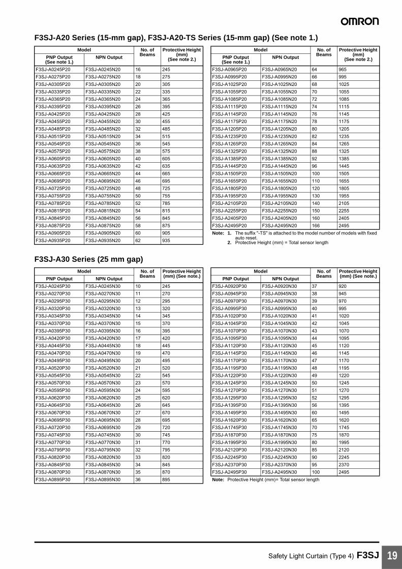
F3SJ-A20 Series (15-mm gap), F3SJ-A20-TS Series (15-mm gap) (See note 1.)
F3SJ-A30 Series (25 mm gap)
Model No. of Beams
Protective Height (mm)
(See note 2.)
Model No. of Beams
Protective Height (mm)
(See note 2.)PNP Output (See note 1.)
NPN Output PNP Output (See note 1.)
NPN Output
F3SJ-A0245P20 F3SJ-A0245N20 16 245 F3SJ-A0965P20 F3SJ-A0965N20 64 965
F3SJ-A0275P20 F3SJ-A0275N20 18 275 F3SJ-A0995P20 F3SJ-A0995N20 66 995
F3SJ-A0305P20 F3SJ-A0305N20 20 305 F3SJ-A1025P20 F3SJ-A1025N20 68 1025
F3SJ-A0335P20 F3SJ-A0335N20 22 335 F3SJ-A1055P20 F3SJ-A1055N20 70 1055
F3SJ-A0365P20 F3SJ-A0365N20 24 365 F3SJ-A1085P20 F3SJ-A1085N20 72 1085
F3SJ-A0395P20 F3SJ-A0395N20 26 395 F3SJ-A1115P20 F3SJ-A1115N20 74 1115
F3SJ-A0425P20 F3SJ-A0425N20 28 425 F3SJ-A1145P20 F3SJ-A1145N20 76 1145
F3SJ-A0455P20 F3SJ-A0455N20 30 455 F3SJ-A1175P20 F3SJ-A1175N20 78 1175
F3SJ-A0485P20 F3SJ-A0485N20 32 485 F3SJ-A1205P20 F3SJ-A1205N20 80 1205
F3SJ-A0515P20 F3SJ-A0515N20 34 515 F3SJ-A1235P20 F3SJ-A1235N20 82 1235
F3SJ-A0545P20 F3SJ-A0545N20 36 545 F3SJ-A1265P20 F3SJ-A1265N20 84 1265
F3SJ-A0575P20 F3SJ-A0575N20 38 575 F3SJ-A1325P20 F3SJ-A1325N20 88 1325
F3SJ-A0605P20 F3SJ-A0605N20 40 605 F3SJ-A1385P20 F3SJ-A1385N20 92 1385
F3SJ-A0635P20 F3SJ-A0635N20 42 635 F3SJ-A1445P20 F3SJ-A1445N20 96 1445
F3SJ-A0665P20 F3SJ-A0665N20 44 665 F3SJ-A1505P20 F3SJ-A1505N20 100 1505
F3SJ-A0695P20 F3SJ-A0695N20 46 695 F3SJ-A1655P20 F3SJ-A1655N20 110 1655
F3SJ-A0725P20 F3SJ-A0725N20 48 725 F3SJ-A1805P20 F3SJ-A1805N20 120 1805
F3SJ-A0755P20 F3SJ-A0755N20 50 755 F3SJ-A1955P20 F3SJ-A1955N20 130 1955
F3SJ-A0785P20 F3SJ-A0785N20 52 785 F3SJ-A2105P20 F3SJ-A2105N20 140 2105
F3SJ-A0815P20 F3SJ-A0815N20 54 815 F3SJ-A2255P20 F3SJ-A2255N20 150 2255
F3SJ-A0845P20 F3SJ-A0845N20 56 845 F3SJ-A2405P20 F3SJ-A2405N20 160 2405
F3SJ-A0875P20 F3SJ-A0875N20 58 875 F3SJ-A2495P20 F3SJ-A2495N20 166 2495
F3SJ-A0905P20 F3SJ-A0905N20 60 905 Note: 1. The suffix "-TS" is attached to the model number of models with fixed auto reset.
2. Protective Height (mm) = Total sensor lengthF3SJ-A0935P20 F3SJ-A0935N20 62 935
Model No. of Beams
Protective Height (mm) (See note.)
Model No. of Beams
Protective Height (mm) (See note.)PNP Output NPN Output PNP Output NPN Output
F3SJ-A0245P30 F3SJ-A0245N30 10 245 F3SJ-A0920P30 F3SJ-A0920N30 37 920
F3SJ-A0270P30 F3SJ-A0270N30 11 270 F3SJ-A0945P30 F3SJ-A0945N30 38 945
F3SJ-A0295P30 F3SJ-A0295N30 12 295 F3SJ-A0970P30 F3SJ-A0970N30 39 970
F3SJ-A0320P30 F3SJ-A0320N30 13 320 F3SJ-A0995P30 F3SJ-A0995N30 40 995
F3SJ-A0345P30 F3SJ-A0345N30 14 345 F3SJ-A1020P30 F3SJ-A1020N30 41 1020
F3SJ-A0370P30 F3SJ-A0370N30 15 370 F3SJ-A1045P30 F3SJ-A1045N30 42 1045
F3SJ-A0395P30 F3SJ-A0395N30 16 395 F3SJ-A1070P30 F3SJ-A1070N30 43 1070
F3SJ-A0420P30 F3SJ-A0420N30 17 420 F3SJ-A1095P30 F3SJ-A1095N30 44 1095
F3SJ-A0445P30 F3SJ-A0445N30 18 445 F3SJ-A1120P30 F3SJ-A1120N30 45 1120
F3SJ-A0470P30 F3SJ-A0470N30 19 470 F3SJ-A1145P30 F3SJ-A1145N30 46 1145
F3SJ-A0495P30 F3SJ-A0495N30 20 495 F3SJ-A1170P30 F3SJ-A1170N30 47 1170
F3SJ-A0520P30 F3SJ-A0520N30 21 520 F3SJ-A1195P30 F3SJ-A1195N30 48 1195
F3SJ-A0545P30 F3SJ-A0545N30 22 545 F3SJ-A1220P30 F3SJ-A1220N30 49 1220
F3SJ-A0570P30 F3SJ-A0570N30 23 570 F3SJ-A1245P30 F3SJ-A1245N30 50 1245
F3SJ-A0595P30 F3SJ-A0595N30 24 595 F3SJ-A1270P30 F3SJ-A1270N30 51 1270
F3SJ-A0620P30 F3SJ-A0620N30 25 620 F3SJ-A1295P30 F3SJ-A1295N30 52 1295
F3SJ-A0645P30 F3SJ-A0645N30 26 645 F3SJ-A1395P30 F3SJ-A1395N30 56 1395
F3SJ-A0670P30 F3SJ-A0670N30 27 670 F3SJ-A1495P30 F3SJ-A1495N30 60 1495
F3SJ-A0695P30 F3SJ-A0695N30 28 695 F3SJ-A1620P30 F3SJ-A1620N30 65 1620
F3SJ-A0720P30 F3SJ-A0695N30 29 720 F3SJ-A1745P30 F3SJ-A1745N30 70 1745
F3SJ-A0745P30 F3SJ-A0745N30 30 745 F3SJ-A1870P30 F3SJ-A1870N30 75 1870
F3SJ-A0770P30 F3SJ-A0770N30 31 770 F3SJ-A1995P30 F3SJ-A1995N30 80 1995
F3SJ-A0795P30 F3SJ-A0795N30 32 795 F3SJ-A2120P30 F3SJ-A2120N30 85 2120
F3SJ-A0820P30 F3SJ-A0820N30 33 820 F3SJ-A2245P30 F3SJ-A2245N30 90 2245
F3SJ-A0845P30 F3SJ-A0845N30 34 845 F3SJ-A2370P30 F3SJ-A2370N30 95 2370
F3SJ-A0870P30 F3SJ-A0870N30 35 870 F3SJ-A2495P30 F3SJ-A2495N30 100 2495
F3SJ-A0895P30 F3SJ-A0895N30 36 895 Note: Protective Height (mm)= Total sensor length
Safety Light Curtain (Type 4) F3SJ20
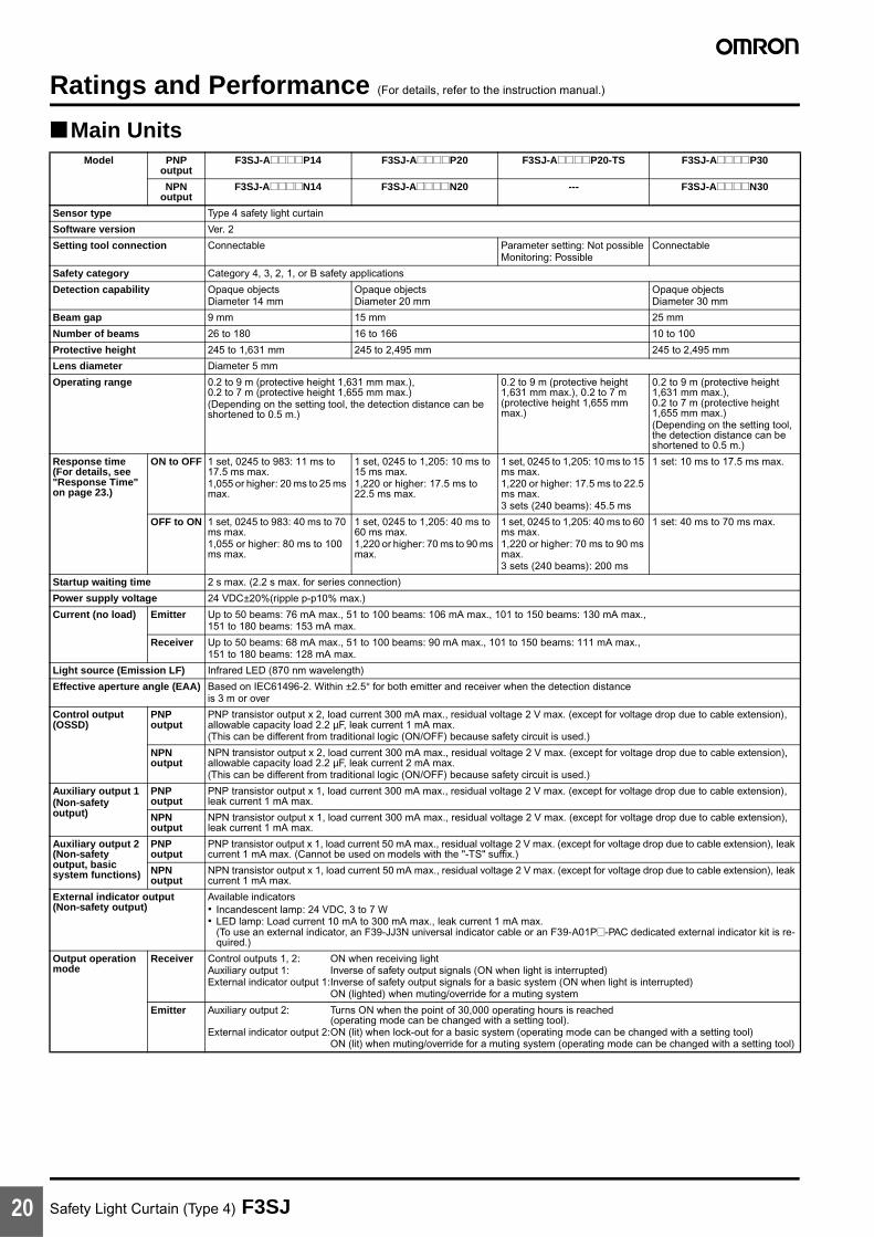
Ratings and Performance (For details, refer to the instruction manual.)
Main UnitsModel PNP
outputF3SJ-A@@@@P14 F3SJ-A@@@@P20 F3SJ-A@@@@P20-TS F3SJ-A@@@@P30
NPN output
F3SJ-A@@@@N14 F3SJ-A@@@@N20 --- F3SJ-A@@@@N30
Sensor type Type 4 safety light curtain
Software version Ver. 2
Setting tool connection Connectable Parameter setting: Not possibleMonitoring: Possible
Connectable
Safety category Category 4, 3, 2, 1, or B safety applications
Detection capability Opaque objectsDiameter 14 mm
Opaque objectsDiameter 20 mm
Opaque objectsDiameter 30 mm
Beam gap 9 mm 15 mm 25 mm
Number of beams 26 to 180 16 to 166 10 to 100
Protective height 245 to 1,631 mm 245 to 2,495 mm 245 to 2,495 mm
Lens diameter Diameter 5 mm
Operating range 0.2 to 9 m (protective height 1,631 mm max.), 0.2 to 7 m (protective height 1,655 mm max.)(Depending on the setting tool, the detection distance can be shortened to 0.5 m.)
0.2 to 9 m (protective height 1,631 mm max.), 0.2 to 7 m (protective height 1,655 mm max.)
0.2 to 9 m (protective height 1,631 mm max.), 0.2 to 7 m (protective height 1,655 mm max.)(Depending on the setting tool, the detection distance can be shortened to 0.5 m.)
Response time (For details, see "Response Time" on page 23.)
ON to OFF 1 set, 0245 to 983: 11 ms to 17.5 ms max.1,055 or higher: 20 ms to 25 ms max.
1 set, 0245 to 1,205: 10 ms to 15 ms max.1,220 or higher: 17.5 ms to 22.5 ms max.
1 set, 0245 to 1,205: 10 ms to 15 ms max.1,220 or higher: 17.5 ms to 22.5 ms max.3 sets (240 beams): 45.5 ms
1 set: 10 ms to 17.5 ms max.
OFF to ON 1 set, 0245 to 983: 40 ms to 70 ms max.1,055 or higher: 80 ms to 100 ms max.
1 set, 0245 to 1,205: 40 ms to 60 ms max.1,220 or higher: 70 ms to 90 ms max.
1 set, 0245 to 1,205: 40 ms to 60 ms max.1,220 or higher: 70 ms to 90 ms max.3 sets (240 beams): 200 ms
1 set: 40 ms to 70 ms max.
Startup waiting time 2 s max. (2.2 s max. for series connection)
Power supply voltage 24 VDC±20%(ripple p-p10% max.)
Current (no load) Emitter Up to 50 beams: 76 mA max., 51 to 100 beams: 106 mA max., 101 to 150 beams: 130 mA max.,151 to 180 beams: 153 mA max.
Receiver Up to 50 beams: 68 mA max., 51 to 100 beams: 90 mA max., 101 to 150 beams: 111 mA max.,151 to 180 beams: 128 mA max.
Light source (Emission LF) Infrared LED (870 nm wavelength)
Effective aperture angle (EAA) Based on IEC61496-2. Within ±2.5° for both emitter and receiver when the detection distanceis 3 m or over
Control output (OSSD)
PNP output
PNP transistor output x 2, load current 300 mA max., residual voltage 2 V max. (except for voltage drop due to cable extension), allowable capacity load 2.2 µF, leak current 1 mA max.(This can be different from traditional logic (ON/OFF) because safety circuit is used.)
NPN output
NPN transistor output x 2, load current 300 mA max., residual voltage 2 V max. (except for voltage drop due to cable extension), allowable capacity load 2.2 µF, leak current 2 mA max.(This can be different from traditional logic (ON/OFF) because safety circuit is used.)
Auxiliary output 1(Non-safety output)
PNP output
PNP transistor output x 1, load current 300 mA max., residual voltage 2 V max. (except for voltage drop due to cable extension), leak current 1 mA max.
NPN output
NPN transistor output x 1, load current 300 mA max., residual voltage 2 V max. (except for voltage drop due to cable extension), leak current 1 mA max.
Auxiliary output 2 (Non-safety output, basic system functions)
PNP output
PNP transistor output x 1, load current 50 mA max., residual voltage 2 V max. (except for voltage drop due to cable extension), leak current 1 mA max. (Cannot be used on models with the "-TS" suffix.)
NPN output
NPN transistor output x 1, load current 50 mA max., residual voltage 2 V max. (except for voltage drop due to cable extension), leak current 1 mA max.
External indicator output(Non-safety output)
Available indicators• Incandescent lamp: 24 VDC, 3 to 7 W• LED lamp: Load current 10 mA to 300 mA max., leak current 1 mA max.
(To use an external indicator, an F39-JJ3N universal indicator cable or an F39-A01P@-PAC dedicated external indicator kit is re-quired.)
Output operation mode
Receiver Control outputs 1, 2: ON when receiving lightAuxiliary output 1: Inverse of safety output signals (ON when light is interrupted)External indicator output 1:Inverse of safety output signals for a basic system (ON when light is interrupted)
ON (lighted) when muting/override for a muting system
Emitter Auxiliary output 2: Turns ON when the point of 30,000 operating hours is reached (operating mode can be changed with a setting tool).
External indicator output 2:ON (lit) when lock-out for a basic system (operating mode can be changed with a setting tool)ON (lit) when muting/override for a muting system (operating mode can be changed with a setting tool)

Safety Light Curtain (Type 4) F3SJ 21
Input voltage PNP output
Test input, interlock selection input, reset input, and muting input are allON voltage: 9 to 24 V (inlet current 3 mA max.)OFF voltage: 0 to 1.5 V, or openExternal device monitoring inputON voltage: 9 to 24 V (inlet current 5 mA max.)OFF voltage: 0 to 1.5 V, or open
Test input, reset input, and muting input are allON voltage: 9 to 24 V
(inlet current 3 mA max.)
OFF voltage: 0 to 1.5 V, or openExternal device monitoring inputON voltage: 9 to 24 V (inlet
current 5 mA max.)
OFF voltage: 0 to 1.5 V, or open
Test input, interlock selection input, reset input, and muting input are allON voltage: 9 to 24 V (inlet
current 3 mA max.)
OFF voltage: 0 to 1.5 V, or openExternal device monitoring inputON voltage: 9 to 24 V (inlet
current 5 mA max.)
OFF voltage: 0 to 1.5 V, or open
NPN output
Test input, interlock selection input, reset input, and muting input are allON voltage: 0 to 1.5 V (short-circuit current 3 mA max.)OFF voltage: 9 to 24 V, or openExternal device monitoring inputON voltage: 0 to 1.5 V (short-circuit current 5 mA max.)OFF voltage: 9 to 24 V, or open
Internal indicators Emitter Light intensity level indicators (green LED × 2, orange LED × 3): ON based on the light intensityError mode indicators (red LED × 3): Blink to indicate error detailsPower indicator (green LED × 1): ON while power is onInterlock indicator (yellow LED × 1): ON while under interlock, ON while under interlock, blinks at lockout.External device monitoring indicator (muting input 1 indicator), Blanking/test indicator (muting input 2 indicator) (green LED × 2): ON/flash according to function
Receiver Light intensity level indicators (green LED × 2, orange LED × 3): ON based on the light intensityError mode indicators (red LED × 3): Blink to indicate error detailsOFF output indicator (red LED × 1): ON when safety output is OFF, blinks at lockout.ON output indicator (green LED × 1): ON while safety output is ON muting error indicator, Blanking /test indicator (green LED × 2): ON/flash according to function
Mutual interference prevention function
Interference light prevention algorithm, detection distance change function
Interference light prevention algorithm
Interference light prevention algorithm, detection distance change function
Series connection Time division emission by series connection• Number of connections: up to 4 sets• Total number of beams: up to 400 beams• Maximum cable length for 2 sets: no longer than 15 m• Response time under connection: See page 23
Time division emission by series connection• Number of connections: up to
3 sets• Total number of beams: up to
240 beams• Maximum cable length for 2
sets: no longer than 15 m • Response time under connec-
tion: See page 23
Time division emission by series connection• Number of connections: up to
4 sets• Total number of beams: up to
400 beams• Maximum cable length for 2
sets: no longer than 15 m• Response time under connec-
tion: See page 23
Test function • Self test (when power is turned ON and when power is supplied)• External test (emission stop function by test input)
Safety-related functions • Start interlock, restart interlock (Must be set with a setting tool when the muting function is used.)
• External device monitor• Muting (Lamp burnout detection, override function included.
F39-CN6 key cap for muting is required.)• Fixed blanking (must be set by a setting tool)• Floating blanking (must be set by a setting tool)
• External device monitor• Muting (Override function in-
cluded. F39-CN6 Key Cap for muting is required.)
• Lockout occurs under either of the following conditions:
• When more than 3 Units are connected in series
• When the total number of beams connected in series ex-ceeds 240
• When any type other than a "-TS" type is mixed in a series connection.
• Start interlock, restart inter-lock (Must be set with a setting tool when the muting function is used.)
• External device monitor• Muting (Lamp burnout detec-
tion, override function includ-ed. F39-CN6 key cap for muting is required.)
• Fixed blanking (must be set by a setting tool)
Floating blanking (must be set by a setting tool)
Connection type Connectors (M12, 8-pin)
Protection circuit Output short-circuit protection, and power supply reverse polarity protection
Ambient temperature During operation: −10 to 55°C (no icing), During storage: −30 to 70°CAmbient humidity During operation: 35 to 85% (no condensation), During storage: 35 to 95%
Operating ambient light intensity
Incandescent lamp: receiving-surface light intensity of 3,000 lx max., Sunlight: receiving-surface light intensity of 10,000 lx max.
Insulation resistance 20 MΩ or higher (500 VDC)
Model PNP output
F3SJ-A@@@@P14 F3SJ-A@@@@P20 F3SJ-A@@@@P20-TS F3SJ-A@@@@P30
NPN output
F3SJ-A@@@@N14 F3SJ-A@@@@N20 --- F3SJ-A@@@@N30

Safety Light Curtain (Type 4) F3SJ22
Dielectric strength voltage 1,000 VAC 50/60 Hz, 1 min
Degree of protection IP65 (IEC60529)
Vibration resistance Malfunction: 10 to 55Hz, double amplitude of 0.7 mm, 20 sweeps in X, Y, and Z directions
Shock resistance Malfunction: 100 m/s2, 1,000 times each in X, Y, and Z directions
Connection cable, Series connection cable (F39-JJR@L, F39-JJR3W)
6-mm-dia., 8-wire cable (0.15 mm2 × 8) with braided shield, allowable bending radius R5 mm
Extension cable (F39-JC@A, F39-JC@B)
6.6-mm-dia., 8-wire cable (0.3 mm2 × 4P, resistance 0.058 Ω/m), allowable bending radius R36 mm (To extend a cable length, use an equivalent or higher-performance cable. Do not place it in the same duct as high-voltage cables or power cables.)For available length for extension (cable extension length), see page 23.
Material Casing (including metal parts on both ends): Aluminum, zinc die-castCap: ABS resinOptical cover: PMMA resin (acrylic)Cable: Oil resistant PVC
Weight (packaged) Calculate using the following equations:(1) For F3SJ-A@@@@P14, weight (g)=(protective height) × 1.7 + α(2) For F3SJ-A@@@@P20/F3SJ-A@@@@P30, weight (g)=(protective height) × 1.5 + αThe values for α are as follows:Protected height 245 to 596 mm: α = 1,100 protected height 1667 to 2180 mm: α = 2,400Protected height 605 to 1,130 mm: α = 1,500 protected height 2195 to 2495 mm: α = 2,600Protected height 1,136 to 1,658 mm: α = 2,000
Accessories Test rod, instruction manual, top/bottom mounting brackets, intermediate mounting brackets (See note.), error mode label, User's Manual (CD-ROM)Note: Number of intermediate mounting brackets depends on protective height of F3SJ.• For protective height from 605 to 1,130 mm: 1 set for each of the emitter and receiver is included• For protective height from 1,136 to 1,658 mm: 2 sets for each of the emitter and receiver are included• For protective height from 1,667 to 2,180 mm: 3 sets for each of the emitter and receiver are included• For protective height from 2,195 to 2,495 mm: 4 sets for each of the emitter and receiver are included
Applicable standards IEC61496-1, EN61496-1 UL61496-1, type 4 ESPE (Electro-Sensitive Protective Equipment)IEC61496-2, prEN61496-2, UL61496-2, type 4 AOPD (Active Opto-electronic Protective Devices)IEC61508, EN61508 SIL3
Model PNP output
F3SJ-A@@@@P14 F3SJ-A@@@@P20 F3SJ-A@@@@P20-TS F3SJ-A@@@@P30
NPN output
F3SJ-A@@@@N14 F3SJ-A@@@@N20 --- F3SJ-A@@@@N30

Safety Light Curtain (Type 4) F3SJ 23
Response Time
Note: Use the following expressions for series connection.For 2-set series connection: Response time (ON to OFF): Response time of the 1st unit + Response time of the 2nd unit - 1 (ms) Response time (OFF to ON): Response time calculated by the above x 4 (ms)For 3-set series connection: Response time (ON to OFF): Response time of the 1st unit + Response time of the 2nd unit - 5 (ms) Response time (OFF to ON): Response time calculated by the above x 5 (ms)
(For models with the "-TS" suffix, multiply the response time obtained by the above x 5 (ms), or use 200 ms, whichever is less.)
For 4-set series connection: Response time (ON to OFF): Response time of the 1st unit + Response time of the 2nd unit + Response time of the 3rd unit +
Response time of the 4th unit - 8 (ms) Response time (OFF to ON): Response time calculated by the above x 5 (ms)
Cable Extension LengthTotal cable extension length must be no greater than the lengths described below.
When the F3SJ and an external power supply are directly connected.
When connected to the F3SP-B1P.
Note: Keep the cable length within the rated length. Failure to do so is dangerous as it may prevent safety functions from operating normally.
Model Protective Height (mm) Number of Beams Response time ms (ON to OFF) Response time ms (OFF to ON)
F3SJ-A@14 series
245 to 263 26 to 28 11 44
281 to 389 30 to 42 12 48
407 to 497 44 to 54 13 52
515 to 605 56 to 66 14 56
623 to 731 68 to 80 15 60
767 to 983 84 to 108 17.5 70
1,055 to 1,271 116 to 140 20 80
1,343 to 1,559 148 to 172 22.5 90
1,631 180 25 100
F3SJ-A@20 seriesF3SJ-A@P20-TS series
245 16 10 40
275 to 425 18 to 28 11 44
435 to 635 30 to 42 12 48
665 to 815 44 to 54 13 52
845 to 995 56 to 66 14 56
1,025 to 1,205 68 to 80 15 60
1,235 to 1,655 82 to 110 17.5 70
1,805 to 1,955 120 to 140 20 80
2,255 to 2,495 150 to 166 22.5 90
F3SJ-A@30 series
245 to 395 10 to 16 10 40
420 to 720 17 to 29 11 44
745 to 1,045 30 to 42 12 48
1,070 to 1,295 43 to 52 13 52
1,395 to 1,620 56 to 65 14 56
1,745 to 1,995 70 to 80 15 60
2,120 to 2,495 85 to 100 17.5 70
Condition 1 set 2 sets 3 sets 4 sets
Using incandescent lamp for auxiliary output and external indicator output
45 m 40 m 30 m 20 m
Not using incandescent lamp 100 m 60 m 45 m 30 m
Condition 1 set 2 sets 3 sets 4 sets
Using incandescent lamp for external indicator output 2
40 m 30 m 25 m 20 m
Using incandescent lamp for external indicator output 1
60 m 45 m 30 m 20 m
Using incandescent lamp for auxiliary output 1
Not using incandescent lamp 100 m 60 m 45 m 30 m
Safety Light Curtain (Type 4) F3SJ24
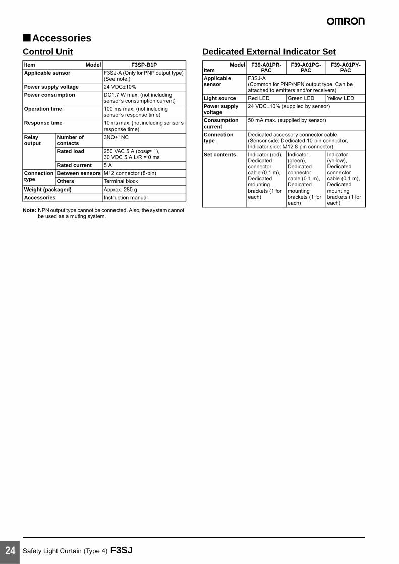
AccessoriesControl Unit
Note: NPN output type cannot be connected. Also, the system cannot be used as a muting system.
Dedicated External Indicator SetItem Model F3SP-B1P
Applicable sensor F3SJ-A (Only for PNP output type) (See note.)
Power supply voltage 24 VDC±10%
Power consumption DC1.7 W max. (not including sensor’s consumption current)
Operation time 100 ms max. (not including sensor’s response time)
Response time 10 ms max. (not including sensor’s response time)
Relay output
Number of contacts
3NO+1NC
Rated load 250 VAC 5 A (cosφ= 1),30 VDC 5 A L/R = 0 ms
Rated current 5 A
Connectiontype
Between sensors M12 connector (8-pin)
Others Terminal block
Weight (packaged) Approx. 280 g
Accessories Instruction manual
ModelItem
F39-A01PR-PAC
F39-A01PG-PAC
F39-A01PY-PAC
Applicable sensor
F3SJ-A(Common for PNP/NPN output type. Can be attached to emitters and/or receivers)
Light source Red LED Green LED Yellow LED
Power supply voltage
24 VDC±10% (supplied by sensor)
Consumption current
50 mA max. (supplied by sensor)
Connection type
Dedicated accessory connector cable (Sensor side: Dedicated 10-pin connector, Indicator side: M12 8-pin connector)
Set contents Indicator (red), Dedicated connector cable (0.1 m), Dedicated mounting brackets (1 for each)
Indicator (green), Dedicated connector cable (0.1 m), Dedicated mounting brackets (1 for each)
Indicator (yellow), Dedicated connector cable (0.1 m), Dedicated mounting brackets (1 for each)
Safety Light Curtain (Type 4) F3SJ 25
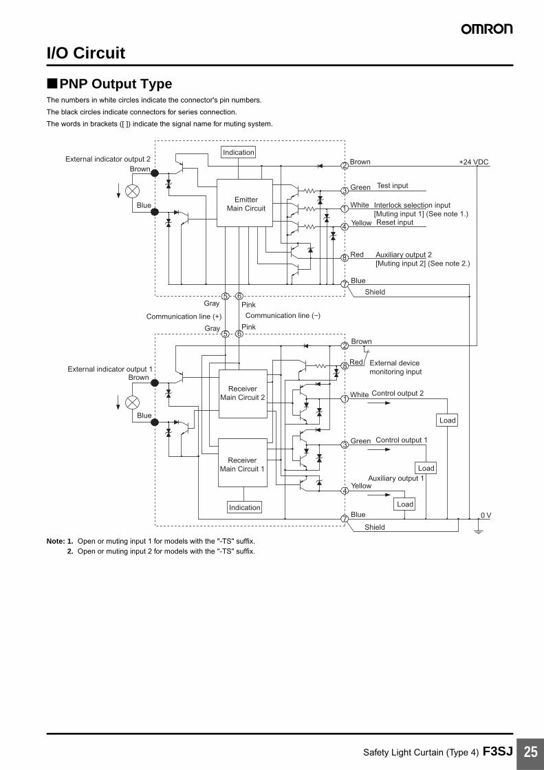
I/O Circuit
PNP Output TypeThe numbers in white circles indicate the connector's pin numbers.
The black circles indicate connectors for series connection.
The words in brackets ([ ]) indicate the signal name for muting system.
Note: 1. Open or muting input 1 for models with the "-TS" suffix.2. Open or muting input 2 for models with the "-TS" suffix.
Shield
Shield
EmitterMain Circuit
Indication
Indication
ReceiverMain Circuit 2
ReceiverMain Circuit 1
+24 VDCBrownBrown
Green Test input
White Interlock selection input [Muting input 1] (See note 1.)
Red Auxiliary output 2 [Muting input 2] (See note 2.)
Reset inputYellow
Blue
Blue
Brown
Blue
Brown
Auxiliary output 1Yellow
Green Control output 1
Red External device monitoring input
White Control output 2
Blue
Load
Load
0 V
Communication line (−)PinkGray
Gray PinkCommunication line (+)
Load
External indicator output 1
External indicator output 2
5
10
5
10
2
8
1
2
3
1
4
7
8
5
5 6
6
3
4
7

Safety Light Curtain (Type 4) F3SJ26
NPN Output TypeThe numbers in white circles indicate the connector's pin numbers.
The black circles indicate connectors for series connection.
The words in brackets ([ ]) indicate the signal name for muting system.
Single-end Connector Cable
Note: 1. Basic system indicates a system with default factory settings.Muting system indicates a system attached with a muting keycap (F39-CN6) to enable muting function.
2. N.C. for models with the "-TS" suffix.
5
10
5
10
2
1
8
1
2
3
1
4
7
8
5
5 6
6
3
4
7Shield
Shield
EmitterMain Circuit
Indication
Indication
ReceiverMain Circuit 2
ReceiverMain Circuit 1
+24 VDCBrownBrown
Green Test input
White Interlock selection input [Muting input 1]
Red Auxiliary output 2 [Muting input 2]
Reset inputYellow
Blue
Blue
Brown
Blue
Brown
Auxiliary output 1
Yellow
Green
Control output 1
Red External device monitoring input
White
Control output 2
Blue
Load
Load
0 V
Communication line (−)PinkGray
Gray PinkCommunication line (+)
Load
External indicator output 1
External indicator output 2
Model Internal wiring Pin No.
Wire color
Signal Name
Basic system (See note 1.) Muting system (See note 1.)
Receiver Emitter Receiver Emitter
F39-JC3A (3 m)
F39-JC7A (7 m)
F39-JC10A (10 m)
F39-JC15A (15 m)
(1) White Safety output 2 Interlock selection input (See note 2.)
Safety output 2 Muting input 1
(2) Brown +24 VDC +24 VDC +24 VDC +24 VDC
(3) Green Safety output 1 Test Input Safety output 1 Test Input
(4) Yellow Auxiliary output 1 Reset input Auxiliary output 1 Reset input
(5) Gray Communication line (+)
Communication line (+)
Communication line (+)
Communication line (+)
(6) Pink Communication line (-)
Communication line (-)
Communication line (-)
Communication line (-)
(7) Blue 0 V 0 V 0 V 0 V
(8) Red External devicemonitoring input
Auxiliary output 2 (See note 2.)
External devicemonitoring input
Muting input 2
48 7
5
32
4 6
1 5
6
7
3
2
1
8
Wire colorWhiteBrownGreenYellowGrayPinkBlueRed

Safety Light Curtain (Type 4) F3SJ 27
Nomenclature
Main Unit and Cables
Component Model Description
Emitter, receiver F3SJ-A@@@@P@@orF3SJ-A@@@@N@@
Select a type name based on the required protective height and detection capability. (Cap and power cable are included)The type name can be understood as follows:F3SJ-A@@@@P@@-@
1: Protective height (mm)2: Output type (P=PNP output type, N=NPN output type)3: Diameter of detection capability (mm)4: L is emitter, D is receiver, and a blank is emitter/receiver set.
For models with fixed auto reset, the suffix "-L-TS" is an emitter, "-D-TS" is a receiver, and "-TS" is an emitter/receiver set.
Extension cable
Single-end connector cable F39-JC@A This extension cable is used to connect to a terminal block controller (e.g. F3SX, G9SA, G9SB, G9SX) or to a safety processing system (e.g. DeviceNet safety).
Double-end connector cable F39-JC@B This extension cable is used when the length of the connection cable is insufficient, or when connecting to an F3SP-B1P controller. The length can be specified.
Emitter
Receiver
Cap
Indicator
Beam
Extension cable
Power cable (Gray)
Power cable (Black)
Beam center-line mark(A line indicates where the beam is aligned. This line indicates the reference line used to measure the safety distance.)
To attach or detach the capand power cable, removethe 4 screws shown above.
1 2 3 4

Safety Light Curtain (Type 4) F3SJ28
Internal Indicators
Total View
Note: 1. Lockout indicator (LOCKOUT) for models with the "-TS" suffix.
No. Internal Indicators Description
For basic system For muting system
1 Light intensity level indicators (LEVEL-1 to 5) (refer to page 29.)
ON Indication status of LEVEL-1 to 5 shows the light intensity level status of the F3SJ.
2 Error mode indicators (ERROR-A to C) (refer to page 29.)
ON/Blinking
Turns ON or blinks only on the sensor where the error occurred when the F3SJ enters lockout. The error mode indicators turn OFF on sensors (emitters or receivers) where an error did not occur, or on other series-connected sensors. The indication status of ERROR-A to C shows the cause of the error. Affix the error mode label (included) near the F3SJ to allow for quick troubleshooting when errors occur.
3 Power indicator (POWER) ON Turns ON while the power is ON.
Blinking Blinks when in maintenance mode.
4 Interlock indicator (INTLK) (See note 1.) ON Turns ON when F3SJ is in interlock state.
Blinking Blinks when under lockout.
5 External device monitoring indicator (EDM)Muting input 1 indicator (MUTE1)
ON Turns ON when an input is given to external device monitoring input.
Turns ON when an input is given to muting input 1.
Blinking Not used Blinks during muting override.
6 Blanking/Test indicator (BLANKING/TEST) Muting input 2 indicator (MUTE2)
ON Turns ON when the blanking function and warning zone function are enabled.
Turns ON when an input is given to muting input 2.
Blinking Blinks when external test is being performed. Blinks during muting override.
7 OFF output indicator (OFF) ON Turns ON when control output is OFF.
Blinking Blinks in the following states:• Lockout state• One or more beams are blocked in maintenance mode
8 ON output indicator (ON) ON Turns ON when safety output is ON.
Blinking Blinks when no beams are blocked in maintenance mode
9 Muting error indicator (MUTING ERR) ON Not used Turns ON when a muting error occurs.
10 Blanking/Test indicator (BLANKING/TEST)
ON Not used Turns ON when the blanking function is enabled.
Blinking Not used Blinks when external test is being performed.
5. External device monitoring indicator (Green) [Muting input 1 indicator]
6. Blanking/Test indicator (Green) [Muting input 2 indicator]
4. Interlock indicator (Yellow) (See note 1.)
3. Power indicator (Green)
ERROR-C (Red)
ERROR-B (Red)
ERROR-A (Red)
LEVEL-1 (Orange)
2. Error mode indicators 2. Error mode indicators
LEVEL-2 (Orange)
LEVEL-3 (Orange)
LEVEL-4 (Green)
LEVEL-5 (Green)
1. Light intensity level indicators
10. Not used (Green) [Blanking/Test indicator]
9. Not used (Green) [Muting error indicator]
8. ON-state indicator (Green)
7. OFF-state indicator (Red)
ERROR-C (Red)
ERROR-B (Red)
ERROR-A (Red)
LEVEL-1 (Orange)
LEVEL-2 (Orange)
LEVEL-3 (Orange)
LEVEL-4 (Green)
LEVEL-5 (Green)
Emitter Receiver
EM
ITT
ER
LEVEL
POWER
INTLK
EDM
BLANKING(TEST)
5
4
3
2
1
C
B
A
5
4
3
2
1
C
B
A
RE
CE
IVE
R
LEVEL
ERROR ERROR
OFF
ON
(See note 2.)
The words in brackets ([ ]) represent the indicator name for the muting.
1. Light intensity level indicators
BLANKING(TEST)
30 dia. 30 dia.

Safety Light Curtain (Type 4) F3SJ 29
2. This label is included with the F39-CN6 key cap for muting. Affix the label when the muting function is used.
Indication Patterns and Intensity Levels of the Light Intensity Level Indicators (LEVEL-1 to 5)
Note: Operation is possible with light intensity level of 100% or more, but to ensure stability, operate when at least 5 of the indication lamps are ON.
Error Mode Indication Patterns and Cause of Errors (ERROR-A to C)
ON OFF
1 2 3 4 5 Light intensity level
170% or higher of control output ON level
From 130 to 170% of control output ON level
From 100 to 130% of control output ON level
From 75 to 100% of control output ON level
From 50 to 75% of control output ON level
Less than 50% of control output ON level
OFF Blinking ON
A B C Cause of error
Mutual interference or ambient incident light.
Power supply voltage of F3SJ is out of the rated range. Insufficient current capacity of power supply.
Incident light to blanking beams.
Failure in communication line.
Emitter and receiver have different F3SJ type names or number of series connections.
Outside the effective range of parameters set by setting tool.
Cap is not attached.
External device monitor failure.
Failure in interlock selection input line or reset input line.
Muting wiring failure.
Failure in control output wiring.
Failure in series connection cable wiring.
Failure in wiring of external display lamp output.
Failure in wiring of auxiliary output.
Broken series connection cable.
Wiring error or broken communications wire.
Influence of electrical noise, or failure in a series-connected F3SJ.

Safety Light Curtain (Type 4) F3SJ30
Safety-related Functions
Interlock FunctionThe F3SJ turns the safety outputs OFF when the power is turned ON or when a beam is interrupted, and maintains this state until a reset signal is applied. This state is called "interlock".
You can reset this interlock by 2 methods; “auto reset that automatically turns safety output ON when an interrupting object is removed” and “manual reset mode that keeps safety output OFF until a reset signal is provided if the interrupting object is removed”.
Auto Reset ModeWhen an interrupting object is removed, safety output automatically turns ON. Auto reset is used on machines where a worker is not able to enter the area between the detection zone and the hazardous part of the machine.
Note: Auto reset is always used in the F3SJ-A@@@@P20-TS series.
Auto reset wiring procedure:
Manual Reset ModeWhen a reset input is given while no interrupting object exists in a detection zone, the safety outputs turn ON. This allows the machine to be manually reset using a reset switch after ensuring safety, preventing unexpected startup.
A sensor enters interlock state when:
• The power is turned ON (start interlock). This is useful if you want to keep the machine stopped until start inspection is completed after the power is turned ON.
• F3SJ is interrupted (restart interlock). After F3SJ is interrupted and the machine stops, the machine can be restarted after safety is ensured.
Manual Reset Wiring Procedure:
To reset:
Note: Install the reset switch outside the hazardous area, where the operator can clearly see the hazardous area.
Interlock Function in a Muting SystemBecause the interlock selection input line is used as muting input 1 when using the muting function, the default setting is auto reset. Use a setting tool for manual reset.
For PNP output For NPN output
1. Open the interlock selection input line, or short-circuit it to 0 to 1.5 V (pin 1/white).
2. Short-circuit the reset input line to 9 to 24 V (pin 4/yellow).
3. Turn ON the power of F3SJ.
1. Open the interlock selection input line, or short-circuit it to 9 to 24 V (pin 1/white).
2. Short-circuit the reset input line to 0 to 1.5 V (pin 4/yellow).
3. Turn ON the power of F3SJ.
Control outputON
OFF
Light incident/Light interrupted
Light incident
Light interrupted
Sensor status Normal operationInterlock state
Reset InputON
OFF
250 ms min.
For PNP output For NPN output
1. Connect the interlock selection input line to 9 to 24 V (pin 1/white).
2. Connect the reset input line to 9 to 24 V via the reset switch (a-contact) (pin 4/yellow).
3. Keep the reset switch contact open, and turn the power of F3SJ ON.
1. Connect the interlock selection input line to 0 to 1.5 V (pin 1/white).
2. Connect the reset input line to 0 to 1.5 V via the reset switch (a-contact) (pin 4/yellow).
3. Keep the reset switch contact open, and turn the power of F3SJ ON.
For PNP output For NPN output
Apply voltage of 9 to 24 V for 250 ms or longer to the reset input line, and set it open or to 0 to 1.5 V.
Apply voltage of 0 to 1.5 V for 250 ms or longer to the reset input line, and set it open or to 9 to 24 V.
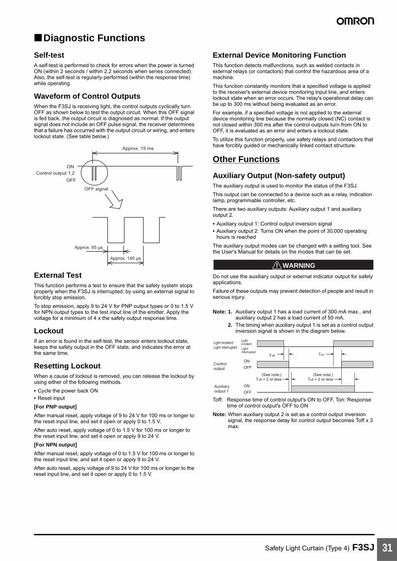
Safety Light Curtain (Type 4) F3SJ 31
Diagnostic Functions
Self-testA self-test is performed to check for errors when the power is turned ON (within 2 seconds / within 2.2 seconds when series connected). Also, the self-test is regularly performed (within the response time) while operating.
Waveform of Control OutputsWhen the F3SJ is receiving light, the control outputs cyclically turn OFF as shown below to test the output circuit. When this OFF signal is fed back, the output circuit is diagnosed as normal. If the output signal does not include an OFF pulse signal, the receiver determines that a failure has occurred with the output circuit or wiring, and enters lockout state. (See table below.)
External TestThis function performs a test to ensure that the safety system stops properly when the F3SJ is interrupted, by using an external signal to forcibly stop emission.
To stop emission, apply 9 to 24 V for PNP output types or 0 to 1.5 V for NPN output types to the test input line of the emitter. Apply the voltage for a minimum of 4 x the safety output response time.
LockoutIf an error is found in the self-test, the sensor enters lockout state, keeps the safety output in the OFF state, and indicates the error at the same time.
Resetting LockoutWhen a cause of lockout is removed, you can release the lockout by using either of the following methods.
• Cycle the power back ON• Reset input
[For PNP output]
After manual reset, apply voltage of 9 to 24 V for 100 ms or longer to the reset input line, and set it open or apply 0 to 1.5 V.
After auto reset, apply voltage of 0 to 1.5 V for 100 ms or longer to the reset input line, and set it open or apply 9 to 24 V.
[For NPN output]
After manual reset, apply voltage of 0 to 1.5 V for 100 ms or longer to the reset input line, and set it open or apply 9 to 24 V.
After auto reset, apply voltage of 9 to 24 V for 100 ms or longer to the reset input line, and set it open or apply 0 to 1.5 V.
External Device Monitoring FunctionThis function detects malfunctions, such as welded contacts in external relays (or contactors) that control the hazardous area of a machine.
This function constantly monitors that a specified voltage is applied to the receiver's external device monitoring input line, and enters lockout state when an error occurs. The relay's operational delay can be up to 300 ms without being evaluated as an error.
For example, if a specified voltage is not applied to the external device monitoring line because the normally closed (NC) contact is not closed within 300 ms after the control outputs turn from ON to OFF, it is evaluated as an error and enters a lockout state.
To utilize this function properly, use safety relays and contactors that have forcibly guided or mechanically linked contact structure.
Other Functions
Auxiliary Output (Non-safety output)The auxiliary output is used to monitor the status of the F3SJ.
This output can be connected to a device such as a relay, indication lamp, programmable controller, etc.
There are two auxiliary outputs: Auxiliary output 1 and auxiliary output 2.
• Auxiliary output 1: Control output inversion signal• Auxiliary output 2: Turns ON when the point of 30,000 operating
hours is reached
The auxiliary output modes can be changed with a setting tool. See the User's Manual for details on the modes that can be set.
!WARNING
Do not use the auxiliary output or external indicator output for safety applications.
Failure of these outputs may prevent detection of people and result in serious injury.
Note: 1. Auxiliary output 1 has a load current of 300 mA max., and auxiliary output 2 has a load current of 50 mA.
2. The timing when auxiliary output 1 is set as a control output inversion signal is shown in the diagram below.
Toff: Response time of control output's ON to OFF, Ton: Response time of control output's OFF to ON
Note: When auxiliary output 2 is set as a control output inversion signal, the response delay for control output becomes Toff x 3 max.
ON
OFF
Control output 1,2
Approx. 15 ms
Approx. 65 µs
OFF signal
Approx. 140 µs
Light incident/Light interrupted
LightincidentLightinterrupted
Auxiliary output 1
ON
OFF
Toff × 2 or less Toff × 2 or less
Control output
ON
OFF
Toff Ton
(See note.) (See note.)

Safety Light Curtain (Type 4) F3SJ32
Selecting the System Configuration
Selection FlowchartThe necessary system configuration varies depending on the functions to be used. Use the following flowchart to decide what kind of system is required.
Note: Refer to the User's Manual to determine whether the functions can be used in combination or not.
NOBasic systemWill the fixed blanking function be used?
Will the floating blanking function be used?Will the detection distance be changed?Will other functions be used or changed?
NO
YESBasic system plus a setting tool for setting or changing parameters
Muting system*Will the fixed blanking function be used?Will the floating blanking function be used?Will the detection distance be changed?Will other functions be used or changed?
NO
YES Muting system* plus a setting tool for setting or changing parameters
YES
*F39-CN6 Key Cap for muting is required.
Will the muting function be used?

Safety Light Curtain (Type 4) F3SJ 33
System Configuration and Connection (Basic system)"Basic system" refers to the F3SJ with its default factory settings. The basic system provides basic safety light curtain functions.
Most functions can be used without performing additional configuration.
Basic Connection
For PNP output (See page 35 for NPN output wiring.)
Wiring when using manual reset mode, external device monitoring
S1 S2K4 K3K2
K1
K1 K2
0 V
24 VDC
Power supply
(Gray) Communication line (+)
Em
itter
Rec
eive
r
(Pink) Communication
line (−)
Shi
eld
0 V
(B
lue)
Aux
iliar
y ou
tput
2 (
Red
)
Inte
rlock
sel
ectio
n in
put (
Whi
te)
Test
inpu
t (G
reen
)
Res
et in
put (
Yello
w)
24 V
(B
row
n)
24 V
(B
row
n)
Ext
erna
l dev
ice
mon
itorin
g in
put (
Red
)
Aux
iliar
y ou
tput
1 (
Yello
w)
Con
trol
out
put 1
(G
reen
)
Con
trol
out
put 2
(W
hite
)
0 V
(B
lue)
Shi
eld
(See note 2.)
(See note 1.)
(See note 1.) (See
note 2.)
S1: External test switchS2: Interlock/lockout reset switchK1, K2: Relay or other device that controls hazardous parts of the machineK3, K4: Load or PLC, etc. (for monitoring)
Note: 1. Use a switch for micro loads (Input specifications: 24 V, 1.8 mA).2. F3SJ operates even when K3 and K4 are not connected.

Safety Light Curtain (Type 4) F3SJ34
Wiring for auto reset modeThe auto reset mode will be enabled when the emitter is wired as shown below.
Wiring when the external device monitoring function will not be used• Use a setting tool to set the external device monitoring function to "Disabled."• When using an auxiliary output 1 that has not been changed (output operation mode is "control output data," and inverse of control output
signals is "Enabled), the external device monitoring function will be disabled when auxiliary output 1 and the external device monitoring input are connected as shown below.
S1 S3K4
Communication line (+) (Gray)
Communication line (−) (Pink)
0 V
24 VDC Power supply
Em
itter
Shi
eld
0 V
(B
lue)
Aux
iliar
y ou
tput
2 (
Red
)
Inte
rlock
sel
ectio
n in
put (
Whi
te)
Test
inpu
t (G
reen
)
Res
et in
put (
Yello
w)
24 V
(B
row
n)
(See note 2.)
Ope
n (See note 1.)
(See note 1.)
S1: External test switchS3: Lockout reset switch (connect to 24 V if the
switch is not necessary)K4: Load or PLC, etc. (for monitoring)
Note: 1. Use a switch for micro loads (Input specifications: 24 V, 1.8 mA).
2. F3SJ operates even when K4 is not connected.
K1 K2K3
0 V
24 VDC
Power supply
(Gray) Communication line (+)
Rec
eive
r
(Pink) Communication line (−)
24 V
(B
row
n)
Ext
erna
l dev
ice
mon
itorin
g in
put (
Red
)
Aux
iliar
y ou
tput
1
(Yel
low
)
Con
trol
out
put 1
(G
reen
)
Con
trol
out
put 2
(W
hite
)
0 V
(B
lue)
Shi
eld
(See note.)
K1, K2: Relay or other device that controls hazardous parts of the machine
K3: Load or PLC, etc. (for monitoring)
Note: When K3 is not necessary, connect auxiliary output 1 only to the external device monitoring input.

Safety Light Curtain (Type 4) F3SJ 35
For NPN output (See page 33 for PNP output wiring.)
Wiring when using manual reset mode, external device monitoring
S1 S2K4 K3K2
K1
K1 K2
0 V
24 VDC
Power supply
(Gray) Communication line (+)
Em
itter
Rec
eive
r
(Pink) Communication
line (−)Shi
eld
0 V
(B
lue)
Aux
iliar
y ou
tput
2 (
Red
)
Inte
rlock
sel
ectio
n in
put (
Whi
te)
Test
inpu
t (G
reen
)
Res
et in
put (
Yello
w)
24 V
(B
row
n)
24 V
(B
row
n)
Ext
erna
l dev
ice
mon
itorin
g in
put (
Red
)
Aux
iliar
y ou
tput
1 (
Yello
w)
Con
trol
out
put 1
(G
reen
)
Con
trol
out
put 2
(W
hite
)
0 V
(B
lue)
Shi
eld
(See note 2.)
(See note 1.)
(See note 1.) (See
note 2.)
S1: External test switchS2: Interlock/lockout reset switchK1, K2: Relay or other device that controls hazardous parts of the machineK3, K4: Load or PLC, etc. (for monitoring)
Note: 1. Use a switch for micro loads (Input specifications: 5 V, 1 mA).2. F3SJ operates even when K3 and K4 are not connected.
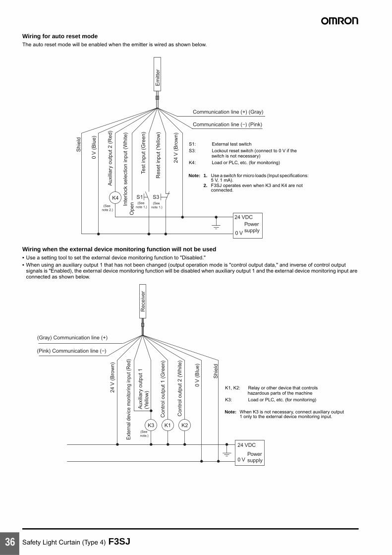
Safety Light Curtain (Type 4) F3SJ36
Wiring for auto reset modeThe auto reset mode will be enabled when the emitter is wired as shown below.
Wiring when the external device monitoring function will not be used• Use a setting tool to set the external device monitoring function to "Disabled."• When using an auxiliary output 1 that has not been changed (output operation mode is "control output data," and inverse of control output
signals is "Enabled), the external device monitoring function will be disabled when auxiliary output 1 and the external device monitoring input are connected as shown below.
S1 S3K4
Communication line (+) (Gray)
Communication line (−) (Pink)
0 V
24 VDC Power supply
Em
itter
Shi
eld
0 V
(B
lue)
Aux
iliar
y ou
tput
2 (
Red
)
Inte
rlock
sel
ectio
n in
put (
Whi
te)
Test
inpu
t (G
reen
)
Res
et in
put (
Yello
w)
24 V
(B
row
n)
(See note 2.)
Ope
n (See note 1.)
(See note 1.)
S1: External test switchS3: Lockout reset switch (connect to 0 V if the
switch is not necessary)K4: Load or PLC, etc. (for monitoring)
Note: 1. Use a switch for micro loads (Input specifications: 5 V, 1 mA).
2. F3SJ operates even when K3 and K4 are not connected.
K1 K2K3
0 V
24 VDC
Power supply
(Gray) Communication line (+)
Rec
eive
r
(Pink) Communication line (−)
24 V
(B
row
n)
Ext
erna
l dev
ice
mon
itorin
g in
put (
Red
)
Aux
iliar
y ou
tput
1
(Yel
low
)
Con
trol
out
put 1
(G
reen
)
Con
trol
out
put 2
(W
hite
)
0 V
(B
lue)
Shi
eld
(See note.)
K1, K2: Relay or other device that controls hazardous parts of the machine
K3: Load or PLC, etc. (for monitoring)
Note: When K3 is not necessary, connect auxiliary output 1 only to the external device monitoring input.

Safety Light Curtain (Type 4) F3SJ 37
Examples of Safety Circuits
For PNP output (See page 42 for NPN output wiring.)Wiring for single F3SJ application (category 4)
• Use of welded relay contact detection and interlock is possible without a controller or relay unit.
Emitter
F39-JC@A-L F39-JC@A-D
Receiver
OUT
PLC
IN
Communicationline (+) (Gray)
Communicationline (−) (Pink)
Shi
eld
0 V
(B
lue)
Aux
iliar
y ou
tput
2 (
Red
)
S1
S2
Test
inpu
t (G
reen
)
Res
et in
put (
Yello
w)
Inte
rlock
sel
ectio
n in
put (
Whi
te)
+24
V (
Bro
wn)
+24
V (
Bro
wn)
Exter
nal d
evice
mon
itorin
g inp
ut (R
ed)
KM1
KM2
Auxil
iary o
utput
1 (Ye
llow)
Contr
ol ou
tput 1
(Gre
en)
Contr
ol ou
tput 2
(Whit
e)
0 V
(B
lue)
Shi
eld
E1+24 VDC
0 V
M
KM2
KM1
KM4
Light incidentLight interrupted
External test switch (S1)
Reset switch (S2)
Control output
KM1,KM2 N.O. contact
KM1,KM2 N.C. contact
PLC input (See note.)
PLC output
KM2KM1
KM3
S1: External test switchS2: Interlock/lockout reset switchKM1, KM2:Safety relay with forcibly-guided contacts
(G7SA) or magnetic contactorKM3: Load, PLC (for monitor)KM4: Solid state contactor (G3J)M: 3-phase motorE1: 24 VDC power supply (S82K)PLC: Programmable controller
(Used for monitoring -- not related to safety system)
Timing Chart
• Manual reset mode• Using external device monitoring
function
Note: The output operation mode for auxiliary output 1 is control output data/inverse of control output signals enabled (default setting).

Safety Light Curtain (Type 4) F3SJ38
Wiring for connection with a controller F3SP-B1P (category 4)
• Reduced wiring due to connector connection• Safety relay included
Emitter Receiver
PLC
IN1 IN2 OUT
S1S2
A1 H1 L1 J1 H1 X1 P1 13 23 33 41
KM3
KM1
KM2
Interlockselection Test Reset Auxiliary
output 1OSSD1 OSSD2 K1
K2
K1 K2
A2 PE T31 T32
External devicemonitoring
14 24 34 42
KM1 KM2
KM1
KM2
F3SP-B1P
F39-JC@B-LF39-JC@B-D
E1+24 VDC
0 V
Light incidentLight interrupted
External test switch (S1)
Reset switch (S2)
Control output
K1,K2 N.O. contact
KM1,KM2 N.O. contact
K1,K2 N.C. contact
KM1,KM2 N.C. contact
PLC input 1 (See note 1.)
PLC input 2
PLC output
M
Wiring for auto reset mode
T32T31
Wiring when the external device monitoring function will not be used
External device monitoring
Included short bar
S1S2
ResetTestInterlock selection
X1H1J1L1H1
S1: External test switchS2: Interlock/lockout reset switchKM1, KM2:Magnetic contactorKM3: Solid state contactor (G3J)M: 3-phase motorE1: 24 VDC power supply (S82K)PLC: Programmable controller
(Used for monitoring -- not related to safety system)
Timing Chart
• Manual reset mode• Using external device monitoring
function
Note: 1. The output operation mode for auxiliary output 1 is control output data/inverse of control output signals enabled (default setting).
2. When the F3SP-B1P is used, the system cannot be used as a muting system.

Safety Light Curtain (Type 4) F3SJ 39
Wiring for connection with a controller F3SX-E-L2R (category 4)
• Emergency stop switch can be connected.• Door switch, two hand control, single beam, or relay unit can be used in combination with F3SX.• Various settings can be changed and input/output terminals can be monitored using the setting support software for F3SX.
Wiring when safety light curtainF3SJ is not used
L2 Module
Emitter ReceiverF3SJ (1st unit)
Model F39-JC@A-Lcable for emitter
Model F39-JC@A-Dcable for receiver
Communicationline (+) (Gray)
Communicationline (−) (Pink)
Shi
eld
0 V
(B
lue)
2 754318 6
15 10121314169 11
(Red
)O
pen
Test
inpu
t (G
reen
)
Res
et in
put (
Yello
w)
Inte
rlock
sel
ectio
n in
put (
Whi
te)
Ope
n
24 V
DC
(B
row
n)
24 V
DC
(B
row
n)
Ext
erna
l dev
ice
m
onito
ring
inpu
t (R
ed)
Auxil
iary
out
put 1
(Yel
low)
Con
trol o
utpu
t 1 (G
reen
)
Con
trol o
utpu
t 1 (G
reen
)
0 V
(B
lue)
Shi
eld
Main Module
S1
S211
12 22
21
24 VDC
E1
A1 T11 T12 T21 T22 Y1 Y2 Y3
Control Circuit
24 VDC
E1
A2
24 VDC
24 VDC
COM
0 V
SSC AS3 AS2 AS1 SS1 SS2 FB
E1
24 VDC RY1 RY2
24 VDC
E1
KM1
KM2
M
Motor controller(operation command)
RY1
RY2
15 10121314169 11
2 754318 6
Relay Output Module
(R Module)
Fuse
12 3424
3311 23
AC
K1
K2
KM1 KM2
Emitter Receiver
Shi
eld
0 V
(B
lue) Ope
n(R
ed)
Test
inpu
t (G
reen
)
Res
et in
put (
Yello
w)
Ope
n
Inte
rlock
sel
ectio
n in
put
(Whi
te)
24 V
DC
(B
row
n)
Communicationline (−) (Pink)
Communicationline (+) (Gray)
24 V
DC
(B
row
n)
Exte
rnal
dev
ice m
onito
ring
inpu
t (Re
d)
Auxil
iary
out
put 1
(Yel
low)
Con
trol o
utpu
t 1 (G
reen
)
Con
trol o
utpu
t 2 (W
hite
)
0 V
(B
lue)
Shi
eld
Model F39-JC@A-Lcable for emitter
Model F39-JC@A-Dcable for receiver
F3SJ (2nd unit)
Wiring when F3SJ'stesting function is used
Shi
eld
Test SW
0 V
(B
lue)
Ope
n (R
ed)
Test
inpu
t (G
reen
)
Res
et in
put (
Yello
w)
Ope
nIn
terlo
ck s
elec
tion
inpu
t (W
hite
)
24 V
DC
(B
row
n)
(See
not
e 2.
)(S
ee n
ote
2.)
(See
not
e 2.
)
Wiring for auto reset mode
S 2
Y 1 Y 2 Y 3
24 VDC
E 1
S1: Emergency stop switch (direct opening contacts)(A165E, A22E)
S2: Reset switchKM1, KM2: Magnetic contactor (LC1D)RY1, RY2: RelayM: 3-phase motorE1: 24 VDC power supply (S82K)
F3SJ settings• Auto reset mode• External device monitoring
function disabled
F3SX-E-L2R settings• Manual reset mode• Using feedback time monitor-
ing function
Note: 1. This wiring example is for category 4.2. This example shows the connection when auxiliary output
1 is in the standard setting (ON when light is interrupted).3. When the F3SJ is series-connected, or 5 or more sets are
connected to the total system of F3SX, power must be supplied to F3SJ from external source. For details, see instruction manual of F3SX.

Safety Light Curtain (Type 4) F3SJ40
Wiring for connection with a controller G9SA-301 (category 4)
F39-JC@A-DF39-JC@A-L
Emitter Receiver
Shi
eld 0 V
(B
lue)
S1
(Red
)O
pen
Test
inpu
t (G
reen
)
Res
et in
put (
Yello
w)
Inte
rlock
sel
ectio
n in
put (
Whi
te)
Ope
n
+24
V (
Bro
wn)
Communicationline (+) (Gray)
Communicationline (−) (Pink)
+24
V (
Bro
wn)
Exte
rnal
dev
ice m
onito
ring
in
put (
Red)
Aux
iliar
y ou
tput
1(Y
ello
w)
Cont
rol o
utpu
t 1 (G
reen
)
Cont
rol o
utpu
t 2 (W
hite
)
0 V
(B
lue)
Shi
eld
IN1 IN2 OUT
PLC
KM3
Light incidentLight interrupted
(S1)
Interlock reset switch(S2)
Emergency stop switch(S3)
Control output
K1,K2 N.O. contact
KM1,KM2 N.O. contact
K1,K2 N.C. contact
KM1,KM2 N.C. contact
PLC input 1 (See note 2.)
PLC input 2
PLC output
M
KM1
KM2E1+24 VDC
0 V
A1 A2 T11 T12
S2
KM1
KM2
T31
K1
34
K2
1
ab
25
T32 41332313
123456
JP
6
N.O.
N.C.
K1 K2
K1
K2
PE T21 T23 T22 A B 14 24 34 42
Control Circuit
KM1 KM2G9SA-301
(See note 1.)
11
12
21
22
S3
External test switch
Wiring for auto reset mode
S 2
Y 1 Y 2 Y 3
24 VDC
E 1
S1: External test switchS2: Interlock reset switchS3: Emergency stop switch (direct opening contacts)
(A165E, A22E)S4: Lockout reset switchKM1, KM2:Magnetic contactorKM3: Solid state contactor (G3J)M: 3-phase motorE1: 24 VDC power supply (S82K)PLC: Programmable controller
(Used for monitoring -- not related to safety system)Timing Chart
F3SJ settings• Auto reset mode• External device monitoring function disabled
G9SA-301 settings• Manual reset mode• Using feedback loop
Using emergency stop switch
Note: 1. If an emergency stop switch is not used, connect control output 1 to T12 terminal and control output 2 to T23 directly.
Note: 2. The output operation mode for auxiliary output 1 is control output data/inverse of control output signals enabled (default setting).
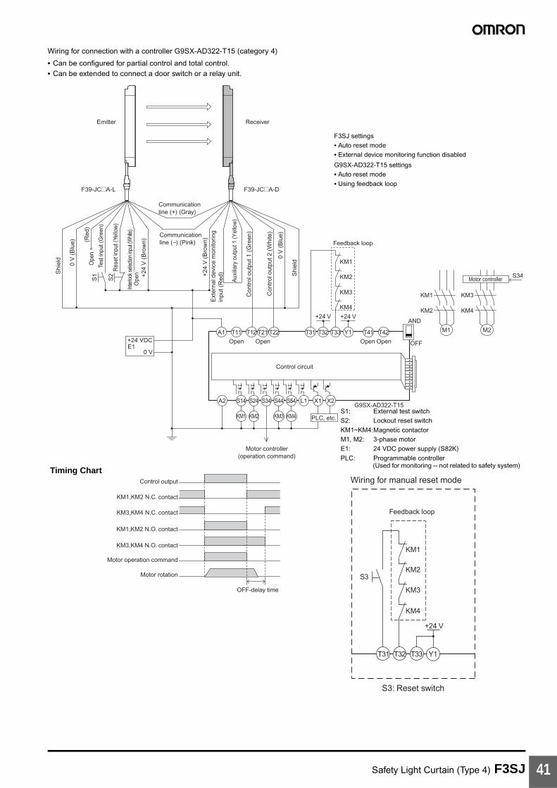
Safety Light Curtain (Type 4) F3SJ 41
Wiring for connection with a controller G9SX-AD322-T15 (category 4)
• Can be configured for partial control and total control.• Can be extended to connect a door switch or a relay unit.
A1
A2 S14 S24
KM1 KM2
S34 S44 S54
KM3 KM4
L1 X1 X2
T11
KM1
KM2
KM3
KM4
+24 V +24 V
T12 T21 T22 T31 T32 T33 Y1 T41 T42 M1 M2
PLC, etc.
Motor controller
Motor controller(operation command)
Feedback loop
Open
G9SX-AD322-T15
Open Open Open OFF
AND
KM1
KM2
KM3
S34
KM4
Control circuit
Control output
KM1,KM2 N.C. contact
KM3,KM4 N.C. contact
KM1,KM2 N.O. contact
KM3,KM4 N.O. contact
Motor operation command
Motor rotation
OFF-delay time
+24
V (
Bro
wn)
0 V
(B
lue)
Con
trol
out
put 1
(G
reen
)
Con
trol
out
put 2
(W
hite
)
Aux
iliar
y ou
tput
1 (Y
ello
w)
S1
S2
Emitter Receiver
Shi
eld
0 V
(B
lue)
Ope
n
Ope
n
Test
inpu
t (G
reen
)
Res
et in
put (
Yello
w)
Inte
rlock
selec
tion
input
(Whit
e)
+24
V (
Bro
wn)
Communicationline (+) (Gray)
Communicationline (−) (Pink)
Ext
erna
l dev
ice
mon
itorin
g
inpu
t (R
ed) Shi
eld
F39-JC@A-DF39-JC@A-L
+24 VDC
0 VE1
(Red
)
+24 V
T32 T33 Y1
KM3
KM4
T31
KM1
KM2S3
Wiring for manual reset mode
Feedback loop
S3: Reset switch
S1: External test switchS2: Lockout reset switchKM1~KM4:Magnetic contactorM1, M2: 3-phase motorE1: 24 VDC power supply (S82K)PLC: Programmable controller
(Used for monitoring -- not related to safety system)Timing Chart
F3SJ settings• Auto reset mode• External device monitoring function disabled
G9SX-AD322-T15 settings• Auto reset mode• Using feedback loop
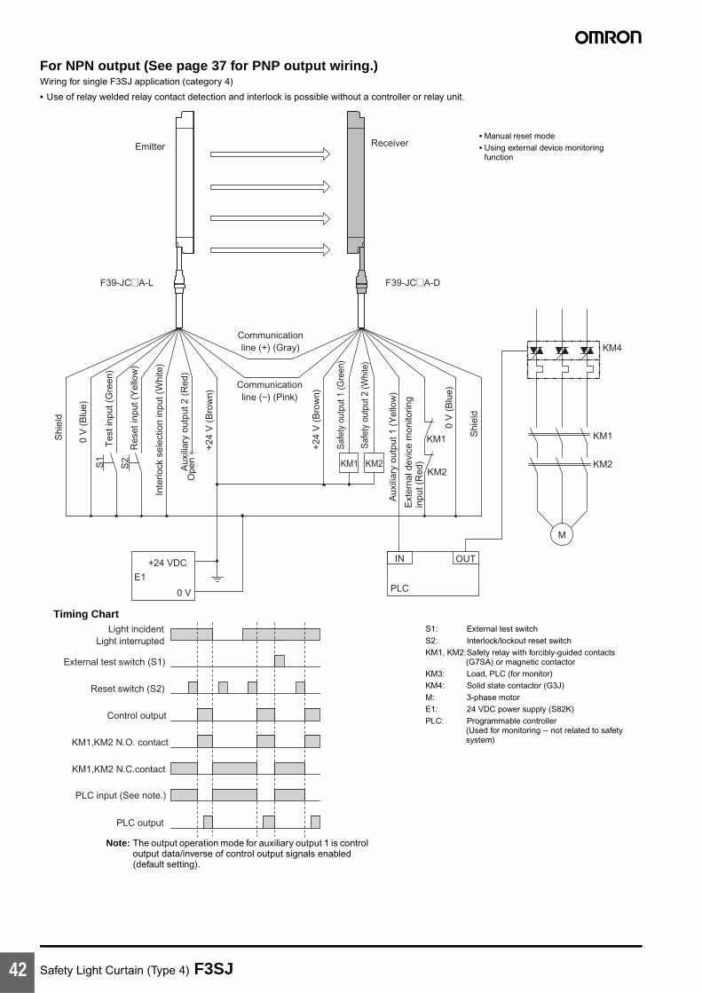
Safety Light Curtain (Type 4) F3SJ42
For NPN output (See page 37 for PNP output wiring.)Wiring for single F3SJ application (category 4)
• Use of relay welded relay contact detection and interlock is possible without a controller or relay unit.
KM1,KM2 N.C.contact
Light incidentLight interrupted
External test switch (S1)
Reset switch (S2)
Control output
KM1,KM2 N.O. contact
PLC input (See note.)
PLC output
+24
V (
Bro
wn)
+24
V (
Bro
wn)
0 V
(B
lue)
0 V
(B
lue)
Saf
ety
outp
ut 1
(Gre
en)
Saf
ety
outp
ut 2
(Whi
te)
Aux
iliar
y ou
tput
1 (
Yel
low
)
Inte
rlock
sel
ectio
n in
put (
Whi
te)
Res
et in
put (
Yel
low
)
Tes
t inp
ut (
Gre
en)
Aux
iliar
y ou
tput
2 (
Red
)
S1
S2
Emitter Receiver
Shi
eld
Shi
eld
Communicationline (−) (Pink)
Communicationline (+) (Gray)
M
KM1
KM2KM1 KM2
OUT
PLC
IN
KM4
KM1
KM2
Ext
erna
l dev
ice
mon
itorin
g in
put (
Red
)
+24 VDC
0 V
E1
Ope
n
F39-JC@A-DF39-JC@A-L
S1: External test switchS2: Interlock/lockout reset switchKM1, KM2:Safety relay with forcibly-guided contacts
(G7SA) or magnetic contactorKM3: Load, PLC (for monitor)KM4: Solid state contactor (G3J)M: 3-phase motorE1: 24 VDC power supply (S82K)PLC: Programmable controller
(Used for monitoring -- not related to safety system)
Timing Chart
• Manual reset mode• Using external device monitoring
function
Note: The output operation mode for auxiliary output 1 is control output data/inverse of control output signals enabled (default setting).

Safety Light Curtain (Type 4) F3SJ 43
Wiring for connection with a controller G9SA-301-P (category 4)
M
OUT
PLC
KM1
KM2
KM1,KM2 N.C. contact
IN1 IN2
PLC input 1 (See note 2.)
Light incidentLight interrupted
External test switch(S1)
Interlock reset switch(S2)
Control output
K1,K2 N.O. contact
KM1,KM2 N.O. contact
K1,K2 N.C. contact
PLC input 2
PLC output
KM3
T23PE 14 24 34 42
41332313T32T31T11
KM1 KM2G9SA-301-P
KM1
KM2
T12
K1K1
K2
K1
T21
S2
+24
V (
Bro
wn)
+24
V (
Bro
wn)
0 V
(B
lue)
0 V
(B
lue)
Cont
rol o
utpu
t 1 (G
reen
)
Cont
rol o
utpu
t 2 (W
hite
)
Aux
iliar
y ou
tput
1(Y
ello
w)
Ext
erna
l dev
ice
mon
itorin
g in
put (
Red
)
Inte
rlock
sel
ectio
n in
put (
Whi
te)
Res
et in
put (
Yel
low
)
Tes
t inp
ut (
Gre
en)
Aux
iliar
y ou
tput
2 (
Red
)
S1
Emitter ReceiverS
hiel
d
Shi
eld
1
a K2
K2b
ControlCircuit
T22 A B
ab
25
Ope
n
634
123456
JP
A2A1
+24 VDC
0 VE1
Ope
n
Emergency stop switch(S3)
Communicationline (−) (Pink)
Communicationline (+) (Gray)
(See note 1.)
11
12
21
22
S3
F39-JC@A-DF39-JC@A-L
A B
Wiring for auto reset mode
ControlCircuit
KM2
KM1
K1
K2
T32T31
S1: External test switchS2: Interlock reset switchS3: Emergency stop switch (direct opening contacts)
(A165E, A22E)S4: Lockout reset switchKM1, KM2: Magnetic contactorKM3: Solid state contactor (G3J)M: 3-phase motorE1: 24 VDC power supply (S82K)PLC: Programmable controller
(Used for monitoring -- not related to safety system)
Timing Chart
F3SJ settings• Auto reset mode• External device monitoring function disabled
G9SA-301-P settings• Manual reset mode• Using feedback loop
Using emergency stop switch
Note: 1. If an emergency stop switch is not used, connect control output 1 to T12 terminal and control output 2 to T23 directly.
Note: 2. The output operation mode for auxiliary output 1 is control output data/inverse of control output signals enabled (default setting).
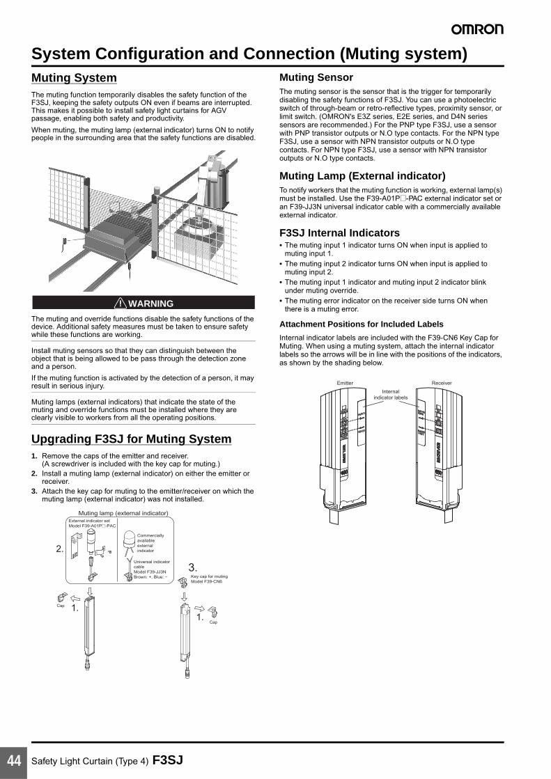
Safety Light Curtain (Type 4) F3SJ44
System Configuration and Connection (Muting system)Muting SystemThe muting function temporarily disables the safety function of the F3SJ, keeping the safety outputs ON even if beams are interrupted. This makes it possible to install safety light curtains for AGV passage, enabling both safety and productivity.
When muting, the muting lamp (external indicator) turns ON to notify people in the surrounding area that the safety functions are disabled.
!WARNING
The muting and override functions disable the safety functions of the device. Additional safety measures must be taken to ensure safety while these functions are working.
Install muting sensors so that they can distinguish between the object that is being allowed to be pass through the detection zone and a person.
If the muting function is activated by the detection of a person, it may result in serious injury.
Muting lamps (external indicators) that indicate the state of the muting and override functions must be installed where they are clearly visible to workers from all the operating positions.
Upgrading F3SJ for Muting System1. Remove the caps of the emitter and receiver.
(A screwdriver is included with the key cap for muting.)2. Install a muting lamp (external indicator) on either the emitter or
receiver.3. Attach the key cap for muting to the emitter/receiver on which the
muting lamp (external indicator) was not installed.
Muting SensorThe muting sensor is the sensor that is the trigger for temporarily disabling the safety functions of F3SJ. You can use a photoelectric switch of through-beam or retro-reflective types, proximity sensor, or limit switch. (OMRON's E3Z series, E2E series, and D4N series sensors are recommended.) For the PNP type F3SJ, use a sensor with PNP transistor outputs or N.O type contacts. For the NPN type F3SJ, use a sensor with NPN transistor outputs or N.O type contacts. For NPN type F3SJ, use a sensor with NPN transistor outputs or N.O type contacts.
Muting Lamp (External indicator)To notify workers that the muting function is working, external lamp(s) must be installed. Use the F39-A01P@-PAC external indicator set or an F39-JJ3N universal indicator cable with a commercially available external indicator.
F3SJ Internal Indicators• The muting input 1 indicator turns ON when input is applied to
muting input 1.• The muting input 2 indicator turns ON when input is applied to
muting input 2.• The muting input 1 indicator and muting input 2 indicator blink
under muting override.• The muting error indicator on the receiver side turns ON when
there is a muting error.
Attachment Positions for Included Labels
Internal indicator labels are included with the F39-CN6 Key Cap for Muting. When using a muting system, attach the internal indicator labels so the arrows will be in line with the positions of the indicators, as shown by the shading below.
Key cap for mutingModel F39-CN6
External indicator setModel F39-A01P@-PAC
Commerciallyavailableexternalindicator
Universal indicator cable Model F39-JJ3NBrown: +, Blue: −
Muting lamp (external indicator)
Cap
Cap1.
1.
2.
3.
Emitter Receiver
Internal indicator labels

Safety Light Curtain (Type 4) F3SJ 45
Standard Muting ModeThe F3SJ is set to this operation mode when it is shipped from the factory. The muting function is enabled by providing a time lag between muting inputs 1 and 2. Use a separately purchased setting tool to change parameters related to muting time, or to select other muting operation modes.
Start ConditionsIf both of the following 2 conditions are present, muting is activated.
1. No interrupting object is found in the F3SJ's detection zone, and control output is ON.
2. After muting input 1 is turned ON (connected to 9 to 24 V for PNP types, or to 0 to 1.5 V for NPN types), muting input 2 is turned ON (connected to 9 to 24 V for PNP types, or to 0 to 1.5 V for NPN types) within the muting input time limit T1 min. to T1 max. (0.03 to 3 s).
Once the conditions in item 2 above are met, the muting function will be enabled in 0.1 s max.
When condition 1 is satisfied but time condition of 2 is not, a muting sequence error occurs and receiver’s muting error indicator turns ON.
However, the F3SJ safety functions will continue operating and the F3SJ will operate normally even during a muting error.
A muting error is released when either of the following occurs:
• When muting is started using a proper procedure• When power is turned on while muting inputs 1 and 2 are OFF
End ConditionsIf either of the following conditions are satisfied, the muting state is released.
1. Muting input 1 or 2 turns OFF for T3 (0.1 s) or longer.2. When the muting continuation time exceeds the muting time limit
of T2 (60 s) (a setting tool can be used to change the limit in the range of 1 to 600 s, or to eliminate the time limit)
• T1 min: Muting input time limit (min.)This is the minimum input time lag between muting inputs 1 and 2, and is set to 0.03 s. If the time lag between muting inputs 1 and 2 are shorter than this value, a muting error is generated.
• T1 max: Muting input time limit (max.)This is the maximum input time lag between muting inputs 1 and 2, and is set to 3 s. The minimum value must be less than the maximum value (min. < max.).
• T2: Muting time limitThis is the continuous time of the muting function, and is set to 60 s. If the muting status exceeds this time, muting is cancelled.
• T3: Allowable pulse-change time for muting input signalsThis is the maximum time allowed for a change in the waveform pulse of muting inputs 1 and 2 while in the muting status.
Note: The muting status can be released even when the system enters lockout.
The following values can be changed using the Setting Support Software for the F3SJ:
• T1 min: Muting input time limit (min.)• T1 max: Muting input time limit (max.)• T2: Muting time limit
The following values can be changed using the Setting Console:
• T2: Muting time limit
Installation Standard for Muting Sensors• Set the muting sensors so that they can detect all of the passing
detection objects (palettes, automobiles, etc.). Do not install in a position so that only the front or rear end of the detection object is detected.
• Set the muting sensors so that they detect the objects even when they are loaded on palettes or other transport devices.
• Install the F3SJ and muting sensors so that each object passes through all muting sensors before the next object arrives at the first muting sensor. Also, install all F3SJ and muting sensors so that no person is able to accidentally enter the hazardous area while the muting function is enabled.
• For a muting sensor installation example, see the instruction manual.
• For details about the override function, see the instruction manual.
Muting input 1
Muting input 2
Muting status
ON
OFF
Enabled
Disabled
F3SJ Light incident/ Light interrupted
Control output
ON
OFF
Light incident
Light interrupted
ON
OFF
Muting lamp (external indicator)
Blink
OFF
0.25 s max.T2 max.
T3 (0.1 s) max.
T3 (0.1 s) max.
T1 min. to T1 max.
0.15 s max.

Safety Light Curtain (Type 4) F3SJ46
Basic Connection for Muting System
For PNP output (See page 47 for NPN output wiring.)
Wiring when using muting and external device monitoring functions
Wiring when the external device monitoring function will not be used• Use a setting tool to set the external device monitoring function to "Disabled."• When using an auxiliary output 1 that has not been changed (output operation mode is "control output data," and inverse of control output
signals is "Enabled), the external device monitoring function will be disabled when auxiliary output 1 and the external device monitoring input are connected as shown below.
K2K1K3
K1
K2B1 A1 S1 S2
0 V
24 VDC
Power supply
Em
itter
Rec
eive
r
(Pink) Communica-tion line (−)S
hiel
d
0 V
(B
lue)
Mut
ing
inpu
t 2
(Red
)M
utin
g in
put 1
(W
hite
)
Test
inpu
t (G
reen
)
Res
et in
put (
Yello
w)
24 V
(B
row
n)
24 V
(B
row
n)Ex
tern
al d
evic
e
mon
itorin
g in
put (
Red
)Au
xiliar
y out
put 1
(Y
ellow
)C
ontro
l out
put 1
(G
reen
)C
ontr
ol o
utpu
t 2
(Whi
te) 0
V (
Blu
e)
Shi
eld
(See note 4.)
(See note 1.)
(See note 1.) (See
note 3.)
(See note 4.)
(Gray) Communication line (+)
(See note 2.)
(See note 4.)
S1: External test switchS2: Lockout reset switch (connect to 24 V if the switch is not necessary)A1: Contact by muting sensor A1B1: Contact by muting sensor B1K1, K2: Relay or other device that controls hazardous parts of the machineK3: Load or PLC, etc. (for monitoring)M1: Muting lamp
Note: 1. Use a switch for small loads (input specifications: 24 V, 1.8 mA)2. When using the interlock function, this also functions as an interlock reset switch. (Must be set with a setting tool.)3. The F3SJ will operate even if K3 is not connected.4. Connect the muting lamp to either the external indicator output or auxiliary output 1 for the emitter or the receiver. When
connecting the muting lamp to auxiliary output 1, the parameter must be changed with a setting tool.
K3 K1 K2
0 V
24 VDC
Power supply
Rec
eive
r
(Pink) Communication line (−)
Ext
erna
l dev
ice
m
onito
ring
inpu
t (R
ed)
Con
trol
out
put 1
(G
reen
)C
ontr
ol o
utpu
t 2
(Whi
te) 0
V (
Blu
e)
Shi
eld
(See note.)
(Gray) Communication line (+)
24 V
(B
row
n)
Aux
iliar
y
outp
ut 1
(Yel
low
)
K1, K2: Relay or other device that controls hazardous parts of the machine
K3: Load, PLC, etc. (for monitoring)
Note: The F3SJ operates even when K3 is not connected.When K3 is not necessary, connect auxiliary output 1 only to the external device monitoring input.
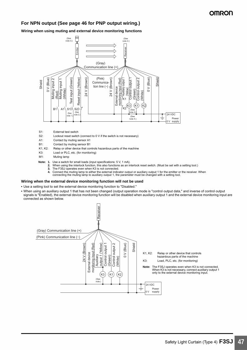
Safety Light Curtain (Type 4) F3SJ 47
For NPN output (See page 46 for PNP output wiring.)
Wiring when using muting and external device monitoring functions
Wiring when the external device monitoring function will not be used• Use a setting tool to set the external device monitoring function to "Disabled."• When using an auxiliary output 1 that has not been changed (output operation mode is "control output data," and inverse of control output
signals is "Enabled), the external device monitoring function will be disabled when auxiliary output 1 and the external device monitoring input are connected as shown below.
K2K1K3
K1
K2B1 A1 S1 S2
0 V
24 VDC
Power supply
Em
itter
Rec
eive
r
(Pink) Communica-tion line (−)S
hiel
d
0 V
(B
lue)
Mut
ing
inpu
t 2
(Red
)M
utin
g in
put 1
(W
hite
)
Test
inpu
t (G
reen
)
Res
et in
put (
Yello
w)
24 V
(B
row
n)
24 V
(B
row
n)
Exte
rnal
dev
ice
m
onito
ring
inpu
t (R
ed)
Auxil
iary o
utpu
t 1
(Yell
ow)
Con
trol o
utpu
t 1
(Gre
en)
Con
trol
out
put 2
(W
hite
) 0 V
(B
lue)
Shi
eld
(See note 1.)
(See note 3.)
(See note 4.)
(Gray) Communication line (+)
(See note 2.)
(See note 4.)
(See note 4.)
S1: External test switchS2: Lockout reset switch (connect to 0 V if the switch is not necessary)A1: Contact by muting sensor A1B1: Contact by muting sensor B1K1, K2: Relay or other device that controls hazardous parts of the machineK3: Load or PLC, etc. (for monitoring)M1: Muting lamp
Note: 1. Use a switch for small loads (input specifications: 5 V, 1 mA).2. When using the interlock function, this also functions as an interlock reset switch. (Must be set with a setting tool.)3. The F3SJ operates even when K3 is not connected.4. Connect the muting lamp to either the external indicator output or auxiliary output 1 for the emitter or the receiver. When
connecting the muting lamp to auxiliary output 1, the parameter must be changed with a setting tool.
K3 K1 K2
0 V
24 VDC
Power supply
Rec
eive
r
(Pink) Communication line (−)
Ext
erna
l dev
ice
m
onito
ring
inpu
t (R
ed)
Con
trol
out
put 1
(G
reen
)C
ontr
ol o
utpu
t 2
(Whi
te) 0
V (
Blu
e)
Shi
eld
(See note.)
(Gray) Communication line (+)
24 V
(B
row
n)
Aux
iliar
y
outp
ut 1
(Ye
llow
)
K1, K2: Relay or other device that controls hazardous parts of the machine
K3: Load, PLC, etc. (for monitoring)
Note: The F3SJ operates even when K3 is not connected.When K3 is not necessary, connect auxiliary output 1 only to the external device monitoring input.

Safety Light Curtain (Type 4) F3SJ48
Example of a Safety Circuit with the Muting System
For PNP outputWiring for muting function with single F3SJ application (category 4)
• Attaching a keycap for muting (F39-CN6) enables the muting function to be used.
Emitter Receiver
OUT
PLC
IN
S1
S2
E124 VDC
0 V
M
KM2
KM1
KM3
Reflector
Light incident
Muting lamp (external indicator)
F39-JC@A-DF39-JC@A-L
KM1 KM2KM2
KM1
Muting sensor (PNP output)
Light interrupted
Control output
Muting input 1
Muting input 2
KM1, KM2 N.O. contact
KM1, KM2 N.C. contact
PLC input (See note 1.)
PLC output
Shi
eld
0 V
(B
lue)
Mut
ing
inpu
t 2
(Red
) Test
inpu
t (G
reen
)
Res
et in
put
(Yel
low
)
Mut
ing
inpu
t 1
(Whi
te)
24 V
(B
row
n)
24 V
(B
row
n)
Ext
erna
l dev
ice
m
onito
ring
inpu
t (R
ed)
Aux
iliar
y ou
tput
1 (
Yello
w)
Con
trol
out
put 1
(G
reen
)
Con
trol
out
put 2
(W
hite
)
0 V
(B
lue)
Shi
eld
(Pink) Communica-tion line (−)
(Gray) Communication line (+)
Note: 1. The output operation mode for auxiliary output 1 is control output data/inverse of control output signals enabled (default setting).
2. Start interlock and restart interlock can be used with a setting tool.
S1: External test switchS2: Lockout reset switchKM1, KM2:Safety relay with forcibly-guided contacts (G7SA) or
magnetic contactorKM3: Solid state contactor (G3J)M: 3-phase motorE1: 24 VDC power supply (S82K)PLC: Programmable controller (Used for monitoring -- not
related to safety system)Muting sensor: Retro-reflective photoelectric sensor (E3Z-R81)
• Auto reset mode• Using external device monitoring
function
Timing Chart

Safety Light Curtain (Type 4) F3SJ 49
For NPN outputWiring for muting function with single F3SJ application (category 4)
• Attaching a keycap for muting (F39-CN6) enables the muting function to be used.
EmitterReceiver
Communicationline (+) (Gray)
Communicationline (−) (Pink)
Shi
eld
0 V
(B
lue)
Mut
ing
inpu
t 2 (R
ed)
Test
inpu
t (G
reen
)
Res
et in
put (
Yello
w)
Mut
ing
inpu
t 1 (W
hite
)
+24
V (
Bro
wn)
+24
V (
Bro
wn)
Contr
ol ou
tput 1
(Gre
en)
Contr
ol ou
tput 2
(Whit
e)
0 V
(B
lue)
Shi
eld
+24 VDC
Reflector
Muting sensor (NPN output)
Auxil
iary o
utput
1 (Ye
llow)
Exter
nal d
evice
mo
nitor
ing in
put (
Red)
KM1,KM2 N.C. contact
Light incidentLight interrupted
Muting input 1
Muting input 2
Control output
KM1,KM2 N.O. contact
PLC input (See note 1.)
PLC output
Muting lamp(external indicator)
F39-JC@A-L
F39-JC@A-D
S1
S2
M
KM1
KM2
OUT
PLC
IN
KM3
KM1
KM2
0V
E1
KM1 KM2
Timing Chart
• Auto reset mode• Using external device monitoring
function
Note: 1. The output operation mode for auxiliary output 1 is control output data/inverse of control output signals enabled (default setting).
2. Start interlock and restart interlock can be used with a setting tool.
S1: External test switchS2: Lockout reset switchKM1, KM2:Safety relay with forcibly-guided contacts (G7SA) or
magnetic contactorKM3: Solid state contactor (G3J)M: 3-phase motorE1: 24 VDC power supply (S82K)PLC: Programmable controller (Used for monitoring -- not
related to safety system)Muting sensor: Retro-reflective photoelectric sensor (E3Z-R61)
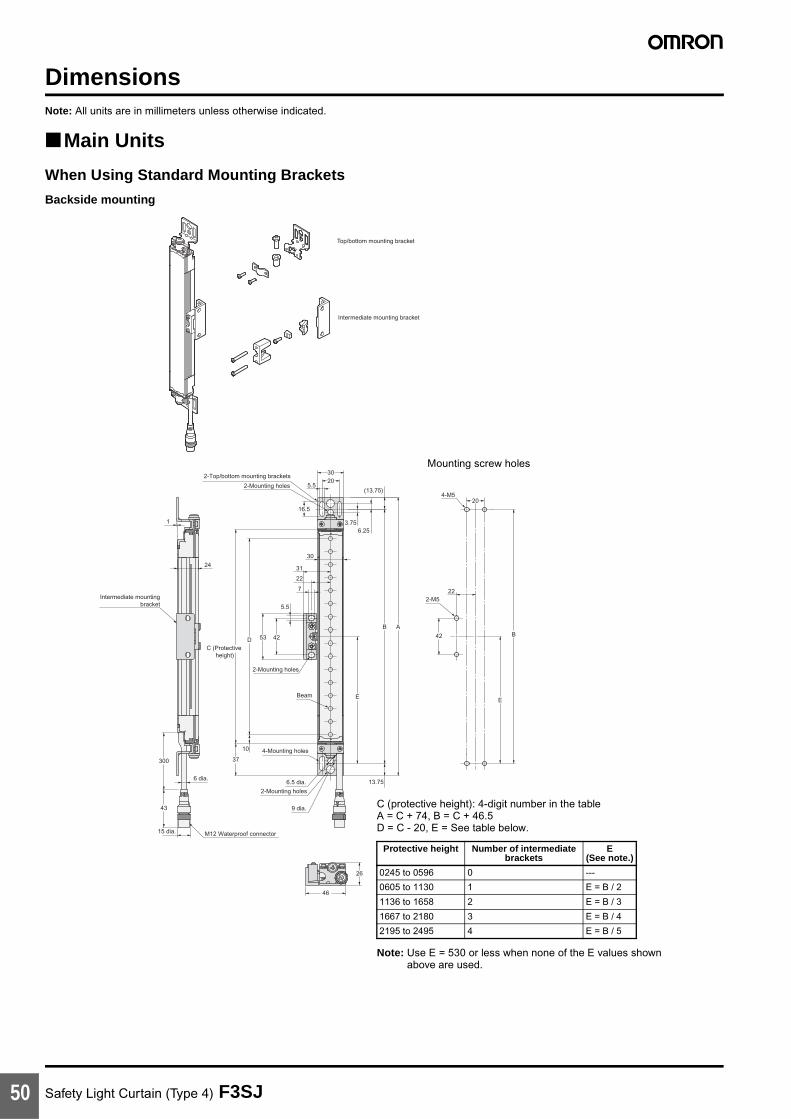
Safety Light Curtain (Type 4) F3SJ50
DimensionsNote: All units are in millimeters unless otherwise indicated.
Main Units
When Using Standard Mounting Brackets
Backside mounting
Top/bottom mounting bracket
Intermediate mounting bracket
1
24
Intermediate mountingbracket
300
43
6 dia.
15 dia. M12 Waterproof connector
9 dia.
13.75
2-Mounting holes
6.5 dia.
4-Mounting holes37
10
Beam E
2-Mounting holes
C (Protective height)
D 53 42
5.5
7
22
31
30
16.5
2-Mounting holes
2-Top/bottom mounting brackets
5.520
20
30
3.756.25
(13.75)
B A
4-M5
222-M5
42
E
B
46
26
C (protective height): 4-digit number in the tableA = C + 74, B = C + 46.5D = C - 20, E = See table below.
Note: Use E = 530 or less when none of the E values shown above are used.
Protective height Number of intermediate brackets
E (See note.)
0245 to 0596 0 ---
0605 to 1130 1 E = B / 2
1136 to 1658 2 E = B / 3
1667 to 2180 3 E = B / 4
2195 to 2495 4 E = B / 5
Mounting screw holes

Safety Light Curtain (Type 4) F3SJ 51
Side mounting
Top/bottom mounting bracket
Intermediate mounting bracket
51
53
5.5
3.75
6.25
(13.75)
24
16.5
2-Mounting holes
2-Top/bottommounting brackets 30
20
10
4336
53
15
M12 Waterproof connector
9 dia.
2-Mounting holes6.5 dia.
6 dia.
43
300
13.75
4-Mounting holes
E
B A
C (Protective height)
D
37
10
5
Beam
31
35
30
2-M5
1531
E
B
4-M520
5.5
11
C (protective height): 4-digit number in the tableA = C + 74, B = C + 46.5D = C - 20, E = See table below.
Note: Use E = 530 or less when none of the E values shown above are used.
Protective height Number of intermediate brackets
E (See note.)
0245 to 0596 0 ---
0605 to 1130 1 E = B / 2
1136 to 1658 2 E = B / 3
1667 to 2180 3 E = B / 4
2195 to 2495 4 E = B / 5
Mounting screw holes

Safety Light Curtain (Type 4) F3SJ52
F39-LJ1 Detailed Dimensions of Bracket
16
2
309 dia.
6.5 dia.
2-M3Through holes
19.621
109 19.6
8 18
11
5.5
36.516.5
14.5
5.5
Material: Stainless steel
13.5
A-A
A
A
9 dia. 12 dia.
11.5
Material: Brass
3021
10
2 - 3.5 dia.
5.6
Material: Stainless steel
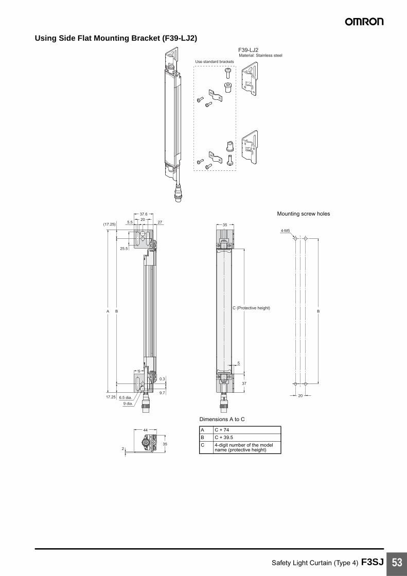
Safety Light Curtain (Type 4) F3SJ 53
Using Side Flat Mounting Bracket (F39-LJ2)F39-LJ2
Use standard brackets
Material: Stainless steel
275.52037.6
25.5
(17.25)
A B
19
6.5 dia.17.25
9 dia.
0.3
9.7
44
352
35
C (Protective height)
37
5
20
4-M5
B
Dimensions A to C
A C + 74
B C + 39.5
C 4-digit number of the model name (protective height)
Mounting screw holes
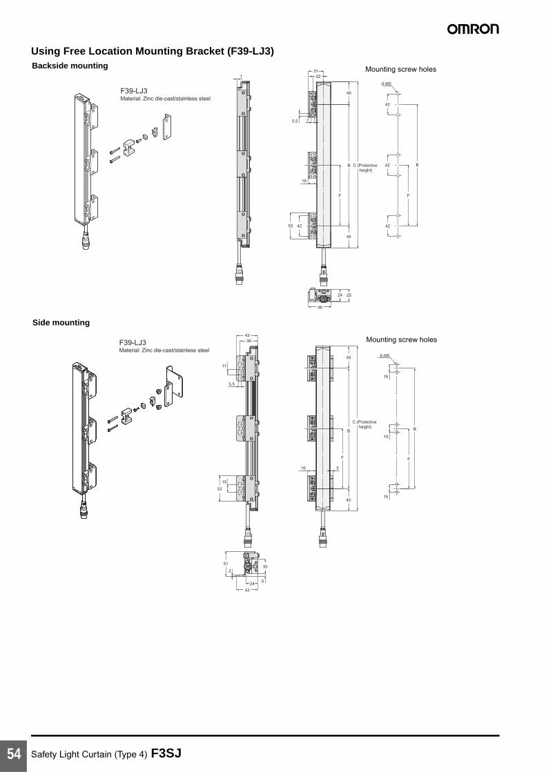
Safety Light Curtain (Type 4) F3SJ54
Using Free Location Mounting Bracket (F39-LJ3)
13122
5.5 7
45
C (Protective height)
B
F
16
4253
45
2524
46
F
B
42
6-M5
42
42
3643
11
5.5
15
53
2
51
43
245
30
45
C (Protective height)
516
45
B
F
B
F
15
6-M5
15
15
Material: Zinc die-cast/stainless steelF39-LJ3
Material: Zinc die-cast/stainless steelF39-LJ3
Backside mounting
Side mounting
Mounting screw holes
Mounting screw holes

Safety Light Curtain (Type 4) F3SJ 55
Dimensions B, C, and F
Dimension F
Note: Use F = 350 or less when none of the F values shown above are used.
When only F39-LJ3 free-location mounting brackets are used without standard brackets, allow a space of at least 350 mm between the brackets. The number of brackets required varies according to the protective height. For details about the number of required brackets, refer to the table below.
The standard included intermediate mounting brackets are the same as the F39-LJ3 free-location mounting brackets. Purchase brackets as necessary if there are fewer intermediate mounting brackets than required. When intermediate mounting brackets are included, they can be used as free-location mounting brackets.
Required number of F39-LJ3 free-location mounting brackets for 1 F3SJ set (emitter/receiver) (2 pieces are included with F39-LJ3)
B C - 90
C 4-digit number of the model name (protective height)
F Depends on the protective height. See the table below.
Protective height Number of intermediate mounting brackets
F(See note.)
0245 to 0440 2 ---
0443 to 0785 3 B / 2
0794 to 1136 4 B / 3
1145 to 1490 5 B / 4
1495 to 1838 6 B / 5
1845 to 2180 7 B / 6
2195 to 2495 8 B / 7
Protective height Number of included free location brackets as
intermediate brackets
Number of free location brackets to mount F3SJ
Number of free location brackets to be purchased
0245 to 0440 0 4 2 sets
0443 to 0596 0 6 3 sets
0605 to 0785 2 6 2 sets
0794 to 1130 2 8 3 sets
1136 4 8 2 sets
1145 to 1490 4 10 3 sets
1495 to 1658 4 12 4 sets
1667 to 1838 6 12 3 sets
1845 to 2180 6 14 4 sets
2195 to 2495 8 16 4 sets
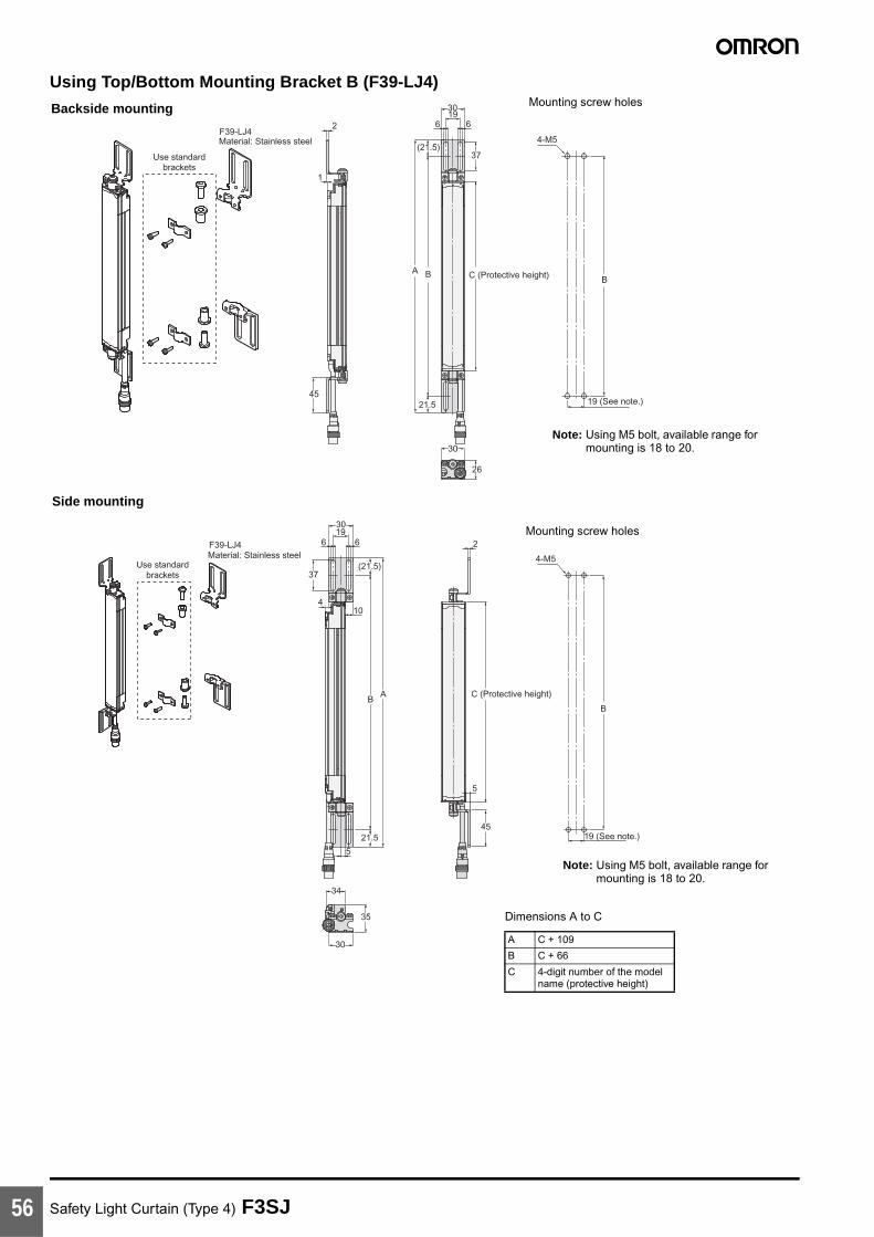
Safety Light Curtain (Type 4) F3SJ56
Using Top/Bottom Mounting Bracket B (F39-LJ4)
F39-LJ4
Use standardbrackets
6 61930
F39-LJ4
Use standardbrackets
2
2
5
1
45
45
37
410
37
6 61930
A
5
B
BA
(21.5)
21.5
21.5
(21.5)
C (Protective height)
C (Protective height)
26
30
35
34
30
19 (See note.)
B
4-M5
19 (See note.)
B
4-M5
Material: Stainless steel
Material: Stainless steel
Backside mounting
Side mounting
Dimensions A to C
A C + 109
B C + 66
C 4-digit number of the modelname (protective height)
Note: Using M5 bolt, available range for mounting is 18 to 20.
Note: Using M5 bolt, available range for mounting is 18 to 20.
Mounting screw holes
Mounting screw holes
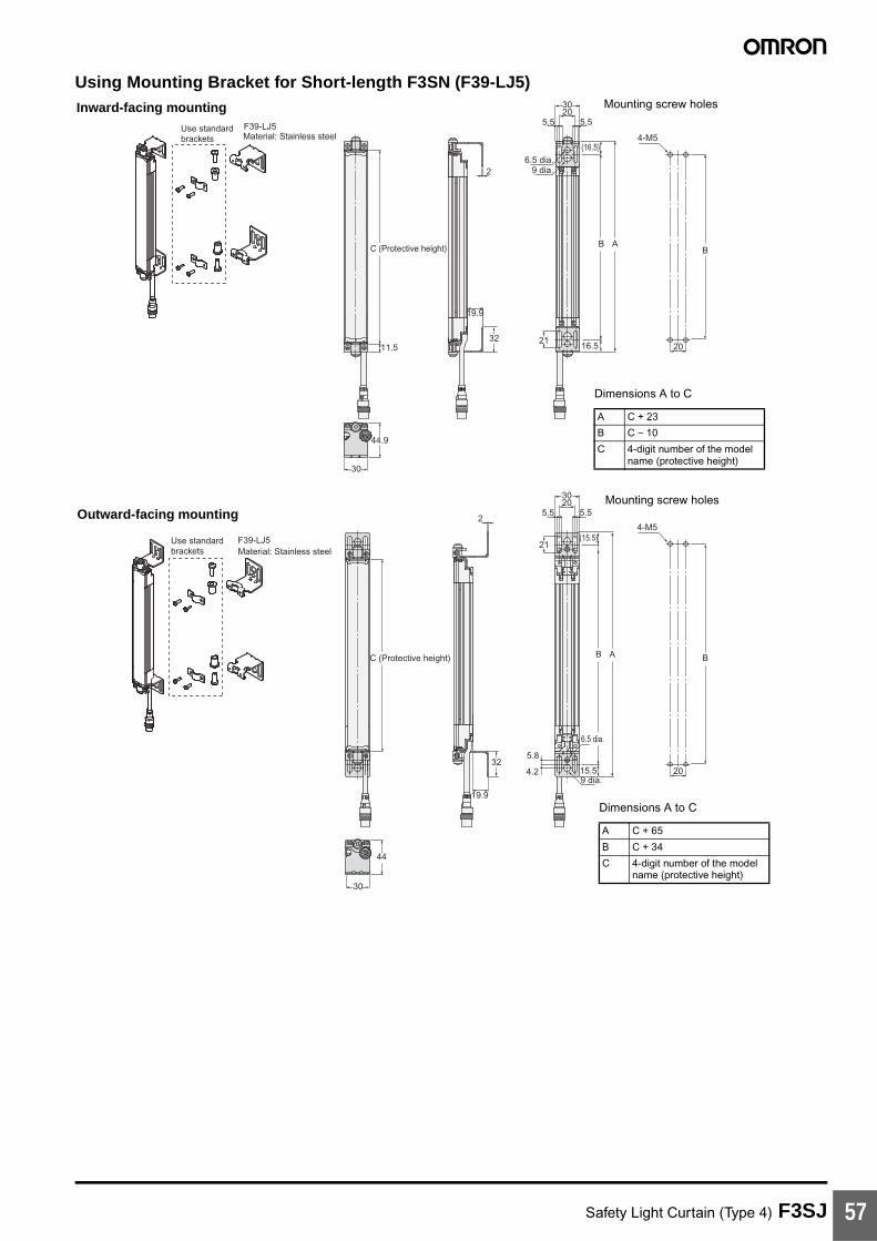
Safety Light Curtain (Type 4) F3SJ 57
Using Mounting Bracket for Short-length F3SN (F39-LJ5)
F39-LJ5Use standardbrackets
F39-LJ5Use standardbrackets
5.5 5.52030
5.5 5.52030
B A
15.5
(15.5)
20
20
B
B
4-M5
4-M5
B A
16.5
(16.5)6.5 dia.
9 dia.
21
9 dia.
6.5 dia.
C (Protective height)
44.9
30
44
30
11.5
C (Protective height)
2
32
21
4.2
5.8
19.9
2
32
19.9
Material: Stainless steel
Material: Stainless steel
Inward-facing mounting
Outward-facing mounting
Dimensions A to C
A C + 65
B C + 34
C 4-digit number of the modelname (protective height)
Dimensions A to C
A C + 23
B C − 10
C 4-digit number of the modelname (protective height)
Mounting screw holes
Mounting screw holes

Safety Light Curtain (Type 4) F3SJ58
F3SN replacement correspondence table (F3SN mounting holes can be used without modification)
When replacing F3SN-@@@@P(N)14 with F3SJ-A@@@@P(N)14
For length greater than F3SN-@0234P(N)14:
Add 11 to the F3SN's 4-digit number and apply it as the F3SJ's 4-digit number, and then replace with the standard brackets included with the product.
[Selection example] F3SN-A0315P(N)14 becomes F3SJ-A0326P(N)14 (replace with standard brackets)
Note: 1. The protective height becomes 11 mm longer.2. Replace with outward-facing mounting of F39-LJ5 when you want to set the detection surface height to be same as the F3SN.
However, the F39-LJ5 and intermediate mounting brackets cannot be mounted simultaneously, so set the protective height to 600 mm or less.
When replacing F3SN-@@@@P (N)25 with F3SJ-A@@@@P (N)20
For length greater than F3SN-@0262P(N)25:
Subtract 17 from the F3SN's 4-digit number and apply it as the F3SJ's 4-digit number, and then replace with the standard brackets included with the product.
[Selection example] F3SN-A0322P(N)25 becomes F3SJ-A0305P(N)20 (replace with standard brackets)
Note: 1. The protective height gets 17 mm shorter.2. Replace with outward-facing mounting of F39-LJ5 when you want to set the detection surface height to be same as the F3SN.
However, the F39-LJ5 and intermediate mounting brackets cannot be mounted simultaneously, so set the protective height to 600 mm or less.
F3SN Replacement F3SJ Replacement method using F39-LJ5Model Protective height Model Protective height
F3SN-@0153P(N)14 153 --- --- ---
F3SN-@0180P(N)14 180 F3SJ-A0245P(N)14 245 Inward-facing mounting
F3SN-@0189P(N)14 189 F3SJ-A0245P(N)14 245 Inward-facing mounting
F3SN-@0198P(N)14 198 F3SJ-A0245P(N)14 245 Inward + outward-facing mounting
F3SN-@0207P(N)14 207 F3SJ-A0245P(N)14 245 Inward + outward-facing mounting
F3SN-@0216P(N)14 216 F3SJ-A0245P(N)14 245 Outward-facing mounting
F3SN-@0225P(N)14 225 F3SJ-A0245P(N)14 245 Outward-facing mounting
F3SN Replacement F3SJ Replacement method using F39-LJ5Model Protective height Model Protective height
F3SN-@0187P(N)25 187 --- --- ---
F3SN-@0217P(N)25 217 F3SJ-A0260P(N)20 260 Inward-facing mounting
F3SN-@0232P(N)25 232 F3SJ-A0260P(N)20 260 Inward + outward-facing mounting
F3SN-@0247P(N)25 247 F3SJ-A0245P(N)20 245 Outward-facing mounting
F39-LJ5Use standardbrackets
5.5 5.52030
20
B A
15.5
(16.5)
6.5 dia.
9 dia.
44
30
(11.5)
C (Protective height)
32.5
2
21
4.2
5.832
19.9
B
4-M5Material: Stainless steel
Inward + outward-facing mounting
Dimensions A to C
A C + 44
B C + 12
C 4-digit number of the modelname (protective height)
Mounting screw holes
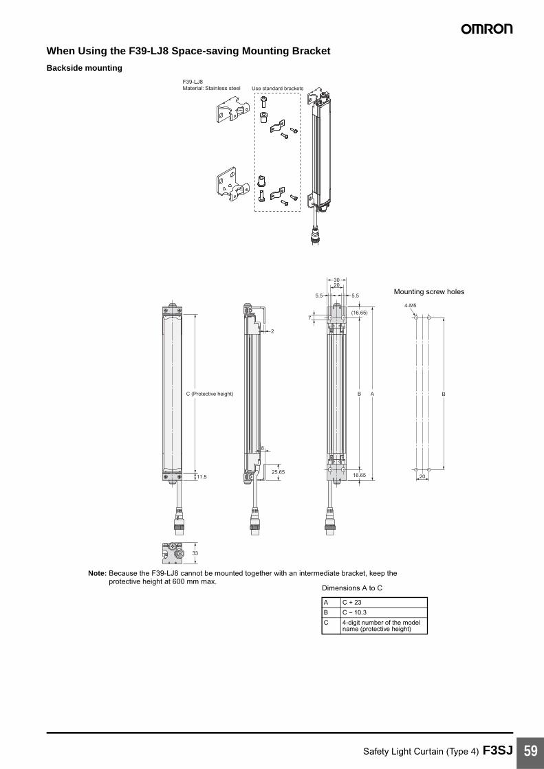
Safety Light Curtain (Type 4) F3SJ 59
When Using the F39-LJ8 Space-saving Mounting Bracket
Backside mounting
Use standard bracketsF39-LJ8Material: Stainless steel
2
B
3020
20
5.5 5.5
7
A
4-M5
B
25.65
8
16.6511.5
33
C (Protective height)
(16.65)
Mounting screw holes
Note: Because the F39-LJ8 cannot be mounted together with an intermediate bracket, keep the protective height at 600 mm max.
Dimensions A to C
A C + 23
B C − 10.3
C 4-digit number of the model name (protective height)
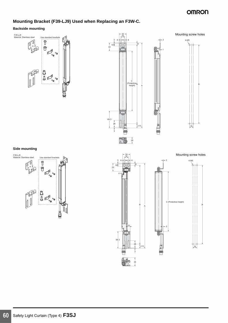
Safety Light Curtain (Type 4) F3SJ60
Mounting Bracket (F39-LJ9) Used when Replacing an F3W-C.
Backside mounting
Side mounting
Use standard bracketsF39-LJ9Material: Stainless steel
8
1
26
B
16
4-M5
C (Protective
height)B
A
(17)
3
28
69.3
3
1033
30
66
16
2
Mounting screw holes
Use standard bracketsF39-LJ9Material: Stainless steel
B BA
8
30
66
16
16
3
1033
4
2
69.3
3
28
10
35
5
4-M5
(17)
C (Protective height)
Mounting screw holes

Safety Light Curtain (Type 4) F3SJ 61
Dimensions A to C
F3W-C replacement correspondence table (F3W-C mounting holes can be used without modification)
When replacing F3W-C@@@ with F3SJ-A@@@@@30
Note: New holes must be drilled for the intermediate bracket.
A C + 102.3
B C + 77.3
C 4-digit number of the model name (protective height)
F3W-C Replacement F3SJ
Model Protective height Model Protective height
F3W-C044 120 --- ---
F3W-C084 280 F3SJ-A0320@30 320
F3W-C124 440 F3SJ-A0470@30 470
F3W-C164 600 F3SJ-A0620@30 (See note.) 620
F3W-C204 760 F3SJ-A0795@30 (See note.) 795
F3W-C244 920 F3SJ-A0945@30 (See note.) 945
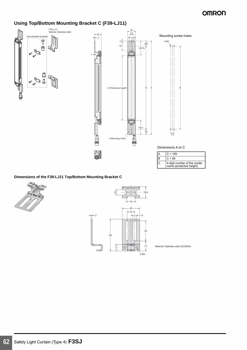
Safety Light Curtain (Type 4) F3SJ62
Using Top/Bottom Mounting Bracket C (F39-LJ11)
Dimensions of the F39-LJ11 Top/Bottom Mounting Bracket C
Use standard brackets
F39-LJ11Material: Stainless steel
26
(20)
13
(54.5)34
3
1330
6
20
54.5
AB BC (Protective height)
2
1
4-Mounting holes
4-M5
Dimensions A to C
A C + 109
B C + 69
C 4-digit number of the model name (protective height)
Mounting screw holes
19.69
16
34
9
54
2
11
13
30
17
2-M3
Material: Stainless steel (SUS304)

Safety Light Curtain (Type 4) F3SJ 63
AccessoriesSingle-end Connector Cable
Cables with Connectors on Both Ends
Insulated vinyl round cable 6.6 dia.8-wire (4-pair) (Cross section of conductor: 0.3 mm2/insulator diameter: 1.15 mm)Standard length L
39.5
15 dia.
L (See note.)
Waterproof connector
F39-JC3A (L = 3 m)F39-JC7A (L = 7 m)
F39-JC10A (L = 10 m) F39-JC15A (L = 15 m)F39-JC20A (L = 20 m)
Color: Emitter (gray) Receiver (black)
Note: Cables with L=3, 7, 10, 15, and 20 m are available.
15 dia. 15 dia.
39.5
Waterproof connector Waterproof connector
43L
Vinyl-insulated round cable: 6.6 dia.8-wire (4-pair) (Cross section of conductor: 0.3 mm2/ Insulator diameter: 1.15 mm)Standard length L
F39-JCR5B (L = 0.5 m)F39-JC1B (L = 1 m)F39-JC3B (L = 3 m)F39-JC5B (L = 5 m)
F39-JC7B (L = 7 m)F39-JC10B (L = 10 m)F39-JC15B (L = 15 m)F39-JC20B (L = 20 m)
Color: Emitter (gray) Receiver (black)
63
45 max.
43
5.6
111 max.
4.6 dia.
35±0.3
2-4.2 dia. or M4
5
84±0.3
R2.3
10.5
9
9
76 max.
13 max.
7×5=35
5.9
24-M3
Receiver
Emitter
91
Control Unit
F3SP-B1P
Mounting screw holes
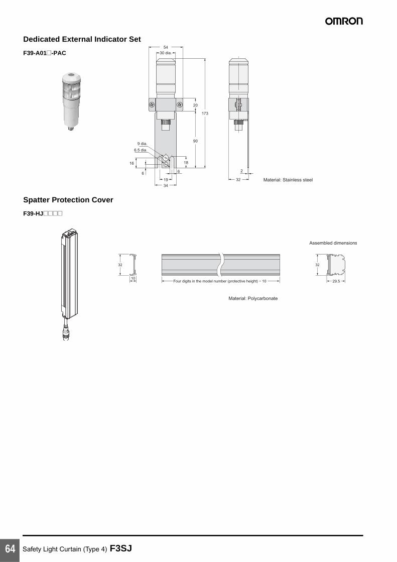
Safety Light Curtain (Type 4) F3SJ64
5430 dia.
9 dia.
6.5 dia.
16
6
1934
6
18
90
173
20
2
32 Material: Stainless steel
Dedicated External Indicator Set
F39-A01@-PAC
32 32
29.5Four digits in the model number (protective height) − 10
Material: Polycarbonate
Assembled dimensions
10
Spatter Protection Cover
F39-HJ@@@@

Safety Light Curtain (Type 4) F3SJ 65
67.9
35.8
17.8
3.6
0.7
(8)
(16)(12)
(4.5)
(625.7)
(46)
Insulated vinyl round cable 4.6 dia.Standard length: 0.5 m
(11.8)
Setting Support Software for the F3SJ
F39-GWUM
22
Communications jack
Channel key
Channel indicator
Function selection indicator
Connection indicator52.8
136
50
Mode indicator
Up cursor key
Right cursor key
Down cursor key
Enter keyDelete key
Left cursor key
Setting Console
F39-MC21
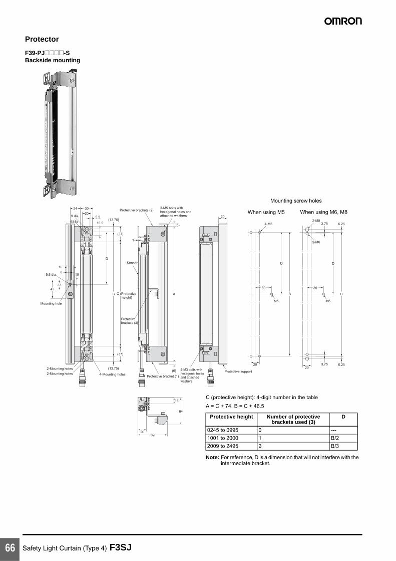
Safety Light Curtain (Type 4) F3SJ66
16.5
5.5
(37)
1
(13.75)
(13.75)
C (Protective height)
AB
D
69
64
15
(6)
(6)
Protective brackets (2)
Protective bracket (1)
Protective brackets (3)
Sensor
20
4323
10
20
3024
9 dia.
5.5 dia.
16
8
Mounting hole
6.5 dia.
(37)
B
M5
39
D
6.25
20
2-M8
2-M6
3.75
3.75 6.25
B
M5
39
D
20
4-M5
2-Mounting holes
2-Mounting holes 4-Mounting holesProtective support
20
3-M5 bolts with hexagonal holes and attached washers
4-M3 bolts with hexagonal holes and attached washers
Protector
F39-PJ@@@@-SBackside mounting
C (protective height): 4-digit number in the table
A = C + 74, B = C + 46.5
Note: For reference, D is a dimension that will not interfere with the intermediate bracket.
Protective height Number of protective brackets used (3)
D
0245 to 0995 0 ---
1001 to 2000 1 B/2
2009 to 2495 2 B/3
When using M5 When using M6, M8
Mounting screw holes

Safety Light Curtain (Type 4) F3SJ 67
16.5
45.5
(37)
(37)
(13.75)
(13.75)
AB
10 20
5.5 dia.36
D
69
643215
(6)
(6)
20
20
20
30 24
9 dia.
8
23
6.5 dia.
5
B
M5
39
D
6.25
20
2-M8
2-M6
3.75
3.75 6.25
B
M5
39
D
20
4-M5
C (Protective height)
Protective brackets (2)
Protective bracket (1)
Protective brackets (4)
Sensor
Mounting hole
2-Mounting holes
2-Mounting holes 4-Mounting holesProtective support
3-M5 bolts with hexagonal holes and attached washers
4-M3 bolts with hexagonal holes and attached washers
Side mounting
C (protective height): 4-digit number in the table
A = C + 74, B = C + 46.5
Note: For reference, D is a dimension that will not interfere with the intermediate bracket.
Protective height Number of protective brackets used (4)
D
0245 to 0995 0 ---
1001 to 2000 1 B/2
2009 to 2495 2 B/3
When using M5 When using M6, M8
Mounting screw holes

Safety Light Curtain (Type 4) F3SJ68
13.5
5.5
20
32
6.5 dia.
(16)
16
2-Mounting brackets (F39-EJ-R)
2
8
9 dia.
60.5 dia.
A B DC (Protective
height)
32
22
8
2
2-M8
2-M6
B B
2020
8
2
4-M5
Water-resistant Case
F39-EJ@@@@-L(D)Backside mounting
Dimensions A to D
A C + 108
B C + 76
C 4-digit number of the model name (protective height)
D C + 44
When using M5 When using M6, M8
Mounting screw holes
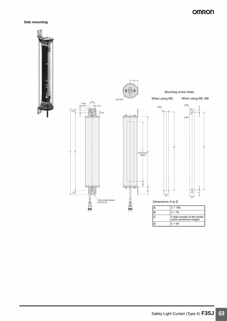
Safety Light Curtain (Type 4) F3SJ 69
2-Mounting brackets (F39-EJ-S)
13.5
5.5
20
6.5 dia.
(16)
16
2
8
9 dia.
A B DC (Protective
height)
32
22
32
60.5 dia.
8
2
2-M8
2-M6
B B
2020
8
2
4-M5
Side mounting
Dimensions A to D
A C + 108
B C + 76
C 4-digit number of the model name (protective height)
D C + 44
When using M5 When using M6, M8
Mounting screw holes

Safety Light Curtain (Type 4) F3SJ70
Comparison with Previous Version
Relationship of Ver. 1 and Ver. 2
Note: Please note that the production of Ver. 1 will be discontinued following the release of Ver. 2 to the market.
Ver. 1/Ver. 2 Compatibility
Note: When using a combination of Ver. 1 and Ver. 2 Units, the settings must be changed for the Ver. 1 F3SJ. Consult your OMRON representative for details on borrowing the Setting Console that is required to change these settings.
Ver. 1 (previous version) Ver. 2 (new version)
Model No. No change
Background color of nameplate
White Yellow
Version description on nameplate
Ver. 1 Ver. 2
Compatibility
When using a combination of a Ver. 1 emitter (receiver) and a Ver. 2 receiver (emitter)
Usage is possible, but it will operate as a Ver. 1 Unit. (See note.)
When Ver. 1 and Ver. 2 are both used in a series connection
Usage is possible, but it will operate as a Ver. 1 Unit. (See note.)
Updating the product from Ver. 1 to Ver. 2 Updating is not possible.

Safety Light Curtain (Type 4) F3SJ 71
Safety PrecautionsThis catalog is intended as a guide for product selection. Be sure to use the instruction manual provided with the product for actual operation.
Regulations and Standards1. Application of an F3SJ-A sensor alone cannot receive type
certification provided by Article 44-2 of the Labour Safety and Health Law of Japan. It is necessary to apply it in a system. Therefore, when using the F3SJ-A in Japan as a "safety system for pressing or shearing machines" prescribed in Article 42 of that law, the system must receive type certification.
2. The F3SJ-A is electro-sensitive protective equipment (ESPE) in accordance with European Union (EU) Machinery Directive Index Annex IV, B, Safety Components, Item 1.
3. The F3SJ-A complies with the following legislation and standards:1. EU Regulations
• Machinery Directive: Directive 98/37/EC• EMC Directive: Directive 89/336/EEC
2. European standards: EN61496-1 (TYPE 4 ESPE), prEN61496-2 (TYPE 4 AOPD), EN61508-1 to -7 (SIL3)
3. International standards: IEC61496-1 (TYPE 4 ESPE), IEC61496-2 (TYPE 4 AOPD), EN61508-1 to -7 (SIL3)
4. JIS standards: JIS B9704-1 (TYPE 4 ESPE), JIS B9704-2 (TYPE 4 AOPD)
4. The F3SJ-A received the following certification from the EU accredited body, TÜV Product Service GmbH:
• EC type test based on machinery directiveType 4 ESPE (EN61496-1),Type 4 AOPD(prEN61496-2)
• EMC Competent Body Certificate (Test power supply: OMRON's S82K)
• TÜV Product Service type certificationType 4 ESPE (EN61496-1),Type 4 AOPD (prEN61496-2),SIL1, 2, 3 (EN61508-1 to -7)Application: EN954-1 categories B, 1, 2, 3, 4
5. The F3SJ-A has received certificates of UL listing for US and Canadian safety standards from the Third Party Assessment Body UL.• Type 4 ESPE (UL61496-1),
Type 4 AOPD (UL61496-2)
6. The F3SJ-A is designed according to the standards listed below. To make sure that the final system complies with the following standards and regulations, you are asked to design and use it in accordance with all other related standards, laws, and regulations. If you have any questions, consult with specialized organizations such as the body responsible for prescribing and/or enforcing machinery safety regulations in the location where the equipment is to be used.• European Standards: EN415-4, EN692, EN693
• US Occupational Safety and Health Administration: OSHA 29 CFR 1910.212
• US Occupational Safety and Health Administration: OSHA 29 CFR 1910.217
• American National Standard Institute: ANSI B11.1 to B11.19
• American National Standard Institute ANSI/RIA 15.06
• Canadian Standards Association CSA Z142, Z432, Z434
• SEMI standard SEMI S2
• Japanese Ministry of Health, Labour and Welfare Announcement: "Guidelines for Comprehensive Safety Standards of Machinery" Announcement No.501, June 1, 2001
Precautions for Safe UseIndication and meaning for safe use
Meanings of Signal Words
To ensure safe use of the F3SJ-A, signal words and an alert symbol are used in this catalog to indicate safety-related instructions. Because these instructions describe details very important to your safety, it is extremely important that you understand and follow the instructions. The signal words and alert symbol used in this catalog are shown below.
!WARNINGIndicates a potentially hazardous situation which, if not avoided, will result in minor or moderate injury, or may result in serious injury or death. Additionally, there may by significant property damage.
!CAUTIONIndicates a potentially hazardous situation which, if not avoided, may result in minor or moderate injury or in property damage.
Definition of Symbol
Warning Labels
For users
!WARNINGThe FS3J must be installed, set, and integrated into the mechanical control system by a qualified technician who has received the appropriate training. Failure to make correct settings may prevent detection of people and result in serious injury.
When changing parameters with a setting tool (F39-GWUM or F39-MC21), the change must be made and the contents of the change must be managed by the person in charge of the system. Unintentional or mistaken parameter changes may prevent detection of people and result in serious injury.
For machines
!WARNINGDo not use this sensor for machines that cannot possibly be stopped by electrical control. For example, do not use it for a pressing machine that uses full-rotation clutch. Otherwise, the machine may not stop before a person reaches the hazardous part, resulting in serious injury.
Do not use the auxiliary output or external indicator output for safety applications. Failure of the F3SJ may cause a person to go undetected, resulting in serious injury.
ProhibitedIndicates a prohibited action.

Safety Light Curtain (Type 4) F3SJ72
For mounting
!WARNINGMake sure to test the operation of the F3SJ after installation to verify that the F3SJ operates as intended. Do not operate the machine until the test has been completed and F3SJ operation has been verified. Unintended function settings may cause a person to go undetected, resulting in serious injury.
Make sure to secure the safety distance between the F3SJ and the hazardous parts. Otherwise, the machine may not stop before a person reaches the hazardous part, resulting in serious injury.
Install a protective structure so that the hazardous part of a machine can only be reached by passing through the sensor's detection zone. Install the sensors so that part of the person is always present in the detection zone when working in a machine's hazardous areas. If a person is able to step into the hazardous area of a machine and remain behind the F3SJ's detection zone, configure the system with an interlock function that prevents the machine from being restarted. Otherwise it may result in heavy injury.
Install the interlock reset switch in a location that provides a clear view of the entire hazardous area and where it cannot be activated from within the hazardous area.
The F3SJ cannot protect a person from an object flying from a hazardous area. Install protective cover(s) or fence(s).
When detection of an area has been disabled by the fixed blanking function, provide a protective structure around the entire area that will prevent a person from passing through it and reaching the hazardous part of the machinery. Failure to do so may prevent detection of people and result in serious injury.
After setting the fixed blanking function, be sure to confirm that a test rod is detected within all areas that require detection. Failure to do so may prevent detection of people and result in serious injury.
When the fixed blanking function or the floating blanking function is used, the diameter for the smallest detectable object becomes larger. Be sure to use the diameter for the smallest detectable object for the fixed blanking function or the floating blanking function when calculating the safety distance. Failure to do so may prevent the machinery from stopping before a person reaches the hazardous part of the machinery, and result in serious injury.
The muting and override functions disable the safety functions of the device. Additional safety measures must be taken to ensure safety while these functions are working.
Install muting sensors so that they can distinguish between the object that is being allowed to be pass through the detection zone and a person. If the muting function is activated by the detection of a person, it may result in serious injury.
Muting lamps (external indicators) that indicate the state of the muting and override functions must be installed where they are clearly visible to workers from all the operating positions.
Position the switch that is used to activate the override function in a location where the entire hazardous area can be seen, and where the switch cannot be operated from inside the hazardous area. Make sure that nobody is in the hazardous area before activating the override function.
Install the sensor system so that it is not affected by reflective surfaces. Failure to do so may hinder detection, resulting in serious injury.
When using more than 1 set of F3SJ, install them so that mutual interference does not occur, such as by configuring series connections or using physical barriers between adjacent sets.
Make sure that the F3SJ is securely mounted and its cables and connectors are properly connected.
Make sure that no foreign material, such as water, oil or dust, enters the inside of the F3SJ while the cap is removed.
Do not use the sensor system with mirrors in as retro-reflective configuration. Doing so may hinder detection. It is possible to use mirrors to "bend" the detection zone to a 90-degree angle.
When using series connections, perform inspection of all connected F3SJs as instructed in the User's Manual.
For wiring
!WARNINGFor PNP output, connect the load between the output and 0 V line.
For NPN output, connect the load between the output and +24 V line. Connecting the load between the +24 V and 0 V lines results in a dangerous condition because the operation mode is reversed to "ON when light is interrupted".
[For PNP output]Do not short-circuit an output line to +24 V line. Otherwise, the output is always ON, creating a dangerous situation. Also, 0 V of the power supply must be grounded so that output should not turn ON due to grounding of the output line.
[For NPN output]Do not short-circuit an output line to 0 V line. Otherwise, the output is always ON, creating a dangerous situation. Also, the +24 V line of the power supply must be grounded so that output does not turn ON due to grounding of the output line.
Configure the system by using the optimal number of control outputs that satisfy the requirements of the necessary safety category.
Do not connect each line of F3SJ to a DC power supply higher than 24 V+20%. Also, do not connect to an AC power supply.Failure to do so may result in electric shock.
Reflector
Position with retro-reflection
Position with detectionzone bent at 90°
Reflector

Safety Light Curtain (Type 4) F3SJ 73
For F3SJ to comply with IEC 61496-1 and UL 508, the DC power supply unit must satisfy all of the following conditions: • Must be within rated power voltage (24 VDC±20%).• Must have tolerance against the total rated current of devices if it is
connected to multiple devices.• Must comply with EMC directives (industrial environment)• Double or enhanced insulation must be applied between the primary
and secondary circuits.• Automatic recovery of overcurrent protection characteristics
(reversed L sagging)• Output holding time must be 20 ms or longer.• Must satisfy output characteristic requirements for class 2 circuit or
limited voltage current circuit defined by UL508.• Must comply with EMC, laws, and regulations of a country or a
region where F3SJ is used. (Ex: In EU, the power supply must comply with EMC Low Voltage Directive.)
Double or enhanced insulation from hazardous voltage must be applied to all input and output lines. Failure to do so may result in electric shock.
The cable extension length must be no greater than the specified length. Otherwise, the safety functions may fail to work properly, resulting in danger.
Others
!WARNINGTo use the F3SJ in PSDI mode (restart of cycle operation by the sensor), you must configure an appropriate circuit between the F3SJ and the machine. For details about PSDI, refer to OSHA1910.217, IEC61496-1, and other relevant standards and regulations.
Do not try to disassemble, repair, or modify this product. Doing so may cause the safety functions to stop working properly.
Do not use the F3SJ in environments where flammable or explosive gases are present. Doing so may result in explosion.
Perform daily and 6-month inspections for the F3SJ. Otherwise, the system may fail to work properly, resulting in serious injury.
Installation ConditionsOperating Range and Approach
!WARNINGInstall a protective structure so that the hazardous part of a machine can only be reached by passing through the sensor's detection zone. Install the sensors so that part of the person is always present in the detection zone when working in a machine's hazardous areas.If a person is able to step into the hazardous area of a machine and remain behind the F3SJ's detection zone, configure the system with an interlock function that prevents the machine from being restarted. Otherwise it may result in heavy injury.
Install the interlock reset switch in a location that provides a clear view of the entire hazardous area and where it cannot be activated from within the hazardous area.
The F3SJ cannot protect a person from an object flying from a hazardous area. Install protective cover(s) or fence(s).
Correct positionThe hazardous area of a machine can be reached only by passing through the sensor's detection zone.
Incorrect positions
A person can only reach the hazardous part of the machinery by passing through the sensor's detection zone.
A person enters the detection zone during operation.
A person can reach the hazardous part of the machinery without passing through the sensor's detection zone.
A person is between the sensor's detection zone and the hazardous part of the machinery.

Safety Light Curtain (Type 4) F3SJ74
Safety DistanceThe safety distance is the distance that must be set between the F3SJ and a machine's hazardous part to stop the hazardous part before a person or object reaches it. The safety distance varies according to the standards of each country and the individual specifications of each machine. In addition, the calculation of the safety distance differs if the direction of approach is not perpendicular to the detection zone of the F3SJ. Always refer to relevant standards.
!WARNINGMake sure to secure the safety distance (S) between the F3SJ and the hazardous part. Otherwise, the machine may not stop before a person reaches the hazardous part, resulting in serious injury.
Note: The response time of a machine is the time period from when the machine receives a stop signal to when the machine's hazardous part stops.Measure the response time on the actual system. Also, periodically check that the response time of the machine has not changed.
How to calculate the safety distance specified by International standard ISO13855-2002 (European standard EN999-1999) (reference)If a person approaches the detection zone of the F3SJ perpendicularly, calculate the safety distance as shown below.
S = K x T + C . . . Eq. (1)
• S: Safety distance• K: Approach speed to the detection zone• T: Total response time of the machine and F3SJ• C: Additional distance calculated by the detection capability of the
F3SJ
System that has detection capability of 40 mm max.Use K = 2,000 mm/s and C = 8 x (d - 14 mm) in equation (1) for the calculation. S = 2,000 mm/s x (Tm + Ts) + 8 x (d - 14 mm)
• S = Safety distance (mm)• Tm = Machine's response time (s)• Ts = Response time of the F3SJ from ON to OFF (s)• d = Size of F3SJ‘s detection capability (mm)
[Calculation example]
When Tm = 0.05 s, Ts = 0.01 s, and d = 14 mm:S = 2,000 mm/s x (0.05 s + 0.01 s) + 8 x (14 mm - 14 mm)= 120 mm . . . Eq. (2)If the result is less than 100 mm, use S = 100 mm.
If the result exceeds 500 mm, use the following equation where K = 1,600 mm/s.
S = 1,600 mm/s x (Tm + Ts) + 8 x (d - 14 mm) . . . Eq. (3)
If the result of this Eq. (3) is less than 500 mm, use S = 500 mm.
Systems with a Smallest Detectable Object Size (Diameter) Greater than 40 mm
Assuming K = 1,600 mm/s and C = 850 mm, the following calculation is made using Eq. (1).
S = 1,600 mm/s x (Tm + Ts) + 850 … Eq. 4,
• S = Safety distance (mm)• Tm = Machine's response time (s)• Ts = Response time of the F3SJ from ON to OFF (s)
Calculation example:
When Tm = 0.05 s and Ts = 0.01 s,
S = 1,600 mm/s x (0.05 s + 0.01 s) + 850 mm = 946 mm
How to calculate the safety distance specified by American standard ANSI B11.19
(Ref.)
If a person approaches the detection zone of the F3SJ perpendicularly, calculate the safety distance as shown below.
S = K x (Ts + Tc + Tr + Tbm) + Dpf
• S: Safety distance• K: Approach speed to the detection zone (the value recommended
by OSHA standard is 1,600 mm/s)
Approach speed K is not specified in the ANSI B.11.19 standard. To determine the value of K to apply, consider all factors, including the operator's physical ability.
• Ts = Machine's stop time (s)• Tr = Response time of the F3SJ from ON to OFF (s)• Tc = Machine control circuit's maximum response time required to
activate its brake (s)• Tbm = Additional time (s)
If a machine has a brake monitor, "Tbm = Brake monitor setting time - (Ts + Tc)". If it has no brake monitor, we recommend using 20% or more of (Ts + Tc) as additional time.
• Dpf = Additional distance
According to ANSI's formula, Dpf is calculated as shown below:
Dpf = 3.4 x (d - 7.0): Where d is the detection capability of the F3SJ (unit: mm)
[Calculation example]
When K = 1,600 mm/s, Ts + Tc = 0.06 s, brake monitor setting time = 0.1 s, Tr = 0.01 s, d = 14 mm:
Tbm = 0.1 - 0.06 = 0.04 s
Dpf = 3.4 x (14 - 7.0) = 23.8 mm
S = 1,600 x (0.06 + 0.01 + 0.04) + 23.8 = 199.8 mm
Hazardous area
Safety distance (S)

Safety Light Curtain (Type 4) F3SJ 75
Distance from Glossy Surface
!WARNINGInstall the sensor system so that it is not affected by reflection from a glossy surface. Failure to do so may hinder detection, resulting in serious injury.
Install the sensor system at distance D or further from highly reflective surfaces such as metallic walls, floors, ceilings, or workpieces, as shown below.
Prevention of Mutual Interference
Mutual interference from other F3SJ is prevented in up to 3 sets without series connection.
For series connectionSeries connection can prevent mutual interference when multiple sensors are used. Up to 4 sets, 400 beams, can be connected.
The emission of series-connected F3SJ is time-divided, so mutual interference does not occur and safety is ensured.
For no series connectionAn interference light prevention algorithm prevents mutual interference in up to 3 unconnected sets. If 4 or more sets of F3SJ are installed and are not connected to each other, arrange them so that mutual interference does not occur. If 2 sets are installed near each other, reflection from the surface of the F3SJ may cause mutual interference. When mutual interference occurs, the F3SJ enters lockout. Combining countermeasures 1 to 3 below is effective.
1. Install a physical barrier
2. Alternate the direction of emission (alternation)
If sensors of 2 sets are installed too close to each other, mutual interference may occur due to reflection by the surface.
This can be resolved by using a setting tool to shorten the detection distance.
Distance between emitter and receiver (Detection Distance)
Allowable installation distance D
For 0.2 to 3 m 0.13 m
For 3 m or more L/2 x tan5° = L x 0.044 (m)
Do not use a sensor system in a reflective configuration.Doing so may hinder detection. Mirrors can be used change the optical route.
When using more than 1 set of F3SJ, install them so that mutual interference does not occur, such as by configuring series connections or using physical barriers between adjacent sets.
L
D
Detection zone
DEmitter Receiver
Reflective ceiling
Reflective floor
L
DEmitter Receiver5°
Reflective surface
5°
Emitter 1 Receiver 1
Emitter 2 Receiver 2
Emitter 3 Receiver 3
Emitter 4 Receiver 4
Emitter 1 Receiver 1 Emitter 2 Receiver 2
Aligned horizontally
Aligned fore and aft
Aligned vertically
Emitter 1Receiver 1 Emitter 2 Receiver 2 Emitter 1 Receiver 1
Receiver 2 Emitter 2
Receiver 1 Emitter 1
Emitter 2 Receiver 2

Safety Light Curtain (Type 4) F3SJ76
3. Shorten the detection distance (Must be set with a setting tool).
4. Keep sufficient distance between them
The installations shown below may cause mutual interference.
When mutual interference occurs, the F3SJ enters lockout.
Distance between emitter and receiver (Detection Distance)
Allowable installation distance D
For 0.2 to 3 m 0.26 m
For 3 m or more L x tan5° = L x 0.088 (m)
Emitter Receiver
Emitter Receiver
Ambient light
Emitter Receiver
Emitter Receiver
Ambient light
Before changing
After changing
Emitter Receiver
Emitter Receiver
Emitter Receiver
Emitter Receiver
D
L
D
5°
5°
Aligned horizontally
Aligned fore and aft
Aligned vertically
Emitter 1 Receiver 1 Emitter 2 Receiver 2 Emitter 1 Receiver 1
Receiver 2Emitter 2
Receiver 1Emitter 1
Emitter 2 Receiver 2
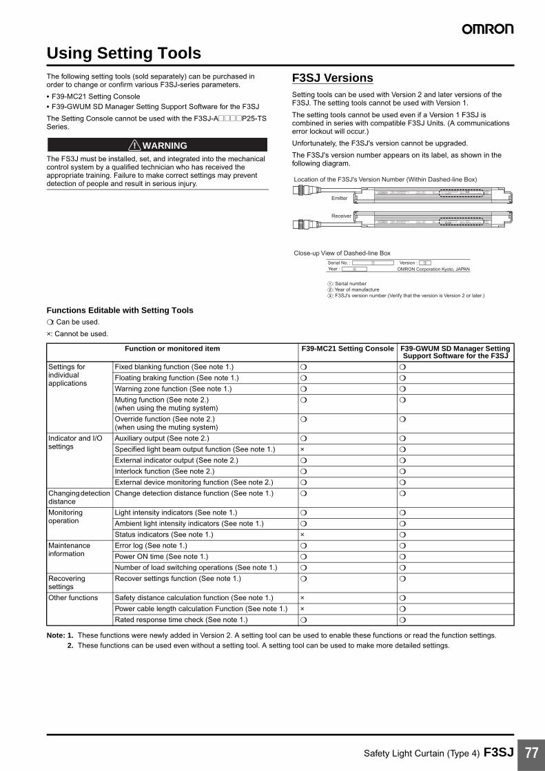
Safety Light Curtain (Type 4) F3SJ 77
Using Setting ToolsThe following setting tools (sold separately) can be purchased in order to change or confirm various F3SJ-series parameters.
• F39-MC21 Setting Console• F39-GWUM SD Manager Setting Support Software for the F3SJ
The Setting Console cannot be used with the F3SJ-A@@@@P25-TS Series.
!WARNINGThe FS3J must be installed, set, and integrated into the mechanical control system by a qualified technician who has received the appropriate training. Failure to make correct settings may prevent detection of people and result in serious injury.
F3SJ VersionsSetting tools can be used with Version 2 and later versions of the F3SJ. The setting tools cannot be used with Version 1.
The setting tools cannot be used even if a Version 1 F3SJ is combined in series with compatible F3SJ Units. (A communications error lockout will occur.)
Unfortunately, the F3SJ's version cannot be upgraded.
The F3SJ's version number appears on its label, as shown in the following diagram.
Functions Editable with Setting Tools : Can be used.
×: Cannot be used.
Note: 1. These functions were newly added in Version 2. A setting tool can be used to enable these functions or read the function settings.2. These functions can be used even without a setting tool. A setting tool can be used to make more detailed settings.
A
B
C
Close-up View of Dashed-line Box
Receiver
Emitter
Location of the F3SJ's Version Number (Within Dashed-line Box)
Serial No. :Year :
Version :OMRON Corporation Kyoto, JAPAN
A: Serial numberB: Year of manufactureC: F3SJ's version number (Verify that the version is Version 2 or later.)
Function or monitored item F39-MC21 Setting Console F39-GWUM SD Manager Setting Support Software for the F3SJ
Settings for individual applications
Fixed blanking function (See note 1.)
Floating braking function (See note 1.)
Warning zone function (See note 1.)
Muting function (See note 2.)(when using the muting system)
Override function (See note 2.)(when using the muting system)
Indicator and I/O settings
Auxiliary output (See note 2.)
Specified light beam output function (See note 1.) ×
External indicator output (See note 2.)
Interlock function (See note 2.)
External device monitoring function (See note 2.)
Changing detection distance
Change detection distance function (See note 1.)
Monitoring operation
Light intensity indicators (See note 1.)
Ambient light intensity indicators (See note 1.)
Status indicators (See note 1.) ×
Maintenance information
Error log (See note 1.)
Power ON time (See note 1.)
Number of load switching operations (See note 1.)
Recovering settings
Recover settings function (See note 1.)
Other functions Safety distance calculation function (See note 1.) ×
Power cable length calculation Function (See note 1.) ×
Rated response time check (See note 1.)
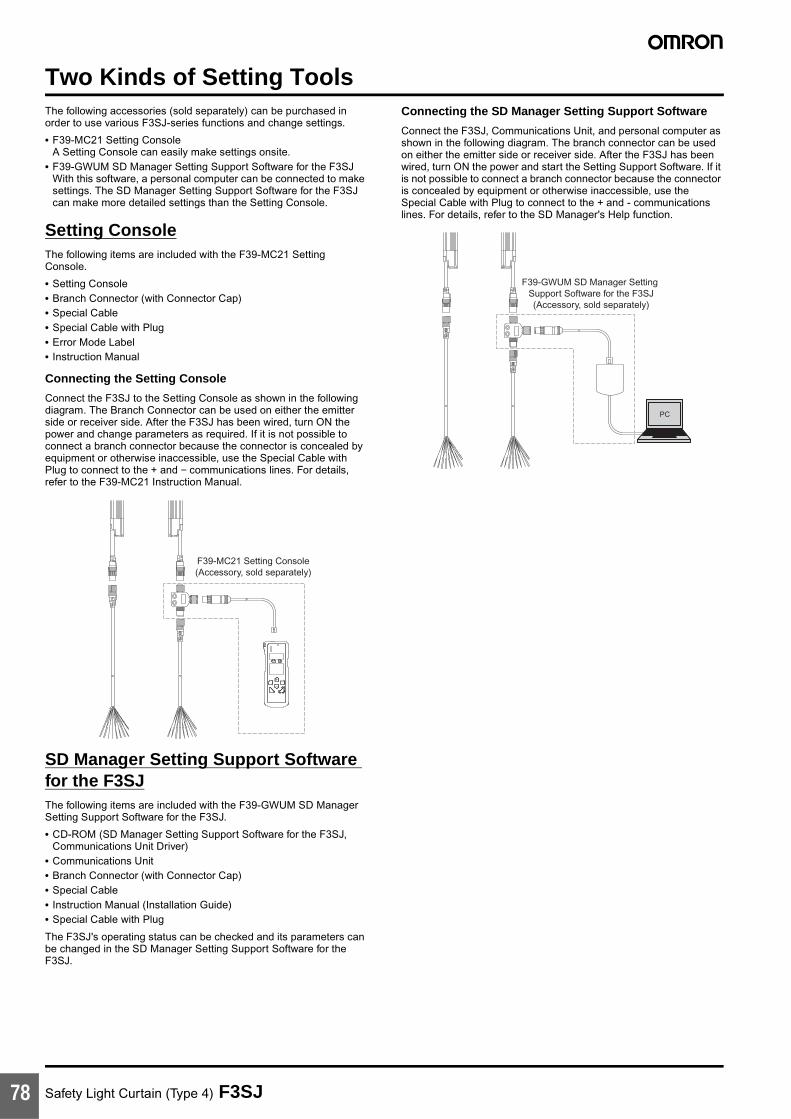
Safety Light Curtain (Type 4) F3SJ78
Two Kinds of Setting ToolsThe following accessories (sold separately) can be purchased in order to use various F3SJ-series functions and change settings.
• F39-MC21 Setting ConsoleA Setting Console can easily make settings onsite.
• F39-GWUM SD Manager Setting Support Software for the F3SJWith this software, a personal computer can be connected to make settings. The SD Manager Setting Support Software for the F3SJ can make more detailed settings than the Setting Console.
Setting ConsoleThe following items are included with the F39-MC21 Setting Console.
• Setting Console• Branch Connector (with Connector Cap) • Special Cable• Special Cable with Plug• Error Mode Label• Instruction Manual
Connecting the Setting Console
Connect the F3SJ to the Setting Console as shown in the following diagram. The Branch Connector can be used on either the emitter side or receiver side. After the F3SJ has been wired, turn ON the power and change parameters as required. If it is not possible to connect a branch connector because the connector is concealed by equipment or otherwise inaccessible, use the Special Cable with Plug to connect to the + and − communications lines. For details, refer to the F39-MC21 Instruction Manual.
SD Manager Setting Support Software for the F3SJThe following items are included with the F39-GWUM SD Manager Setting Support Software for the F3SJ.
• CD-ROM (SD Manager Setting Support Software for the F3SJ, Communications Unit Driver)
• Communications Unit• Branch Connector (with Connector Cap)• Special Cable• Instruction Manual (Installation Guide)• Special Cable with Plug
The F3SJ's operating status can be checked and its parameters can be changed in the SD Manager Setting Support Software for the F3SJ.
Connecting the SD Manager Setting Support Software
Connect the F3SJ, Communications Unit, and personal computer as shown in the following diagram. The branch connector can be used on either the emitter side or receiver side. After the F3SJ has been wired, turn ON the power and start the Setting Support Software. If it is not possible to connect a branch connector because the connector is concealed by equipment or otherwise inaccessible, use the Special Cable with Plug to connect to the + and - communications lines. For details, refer to the SD Manager's Help function.
F39-MC21 Setting Console(Accessory, sold separately)
F39-GWUM SD Manager Setting Support Software for the F3SJ(Accessory, sold separately)
PC
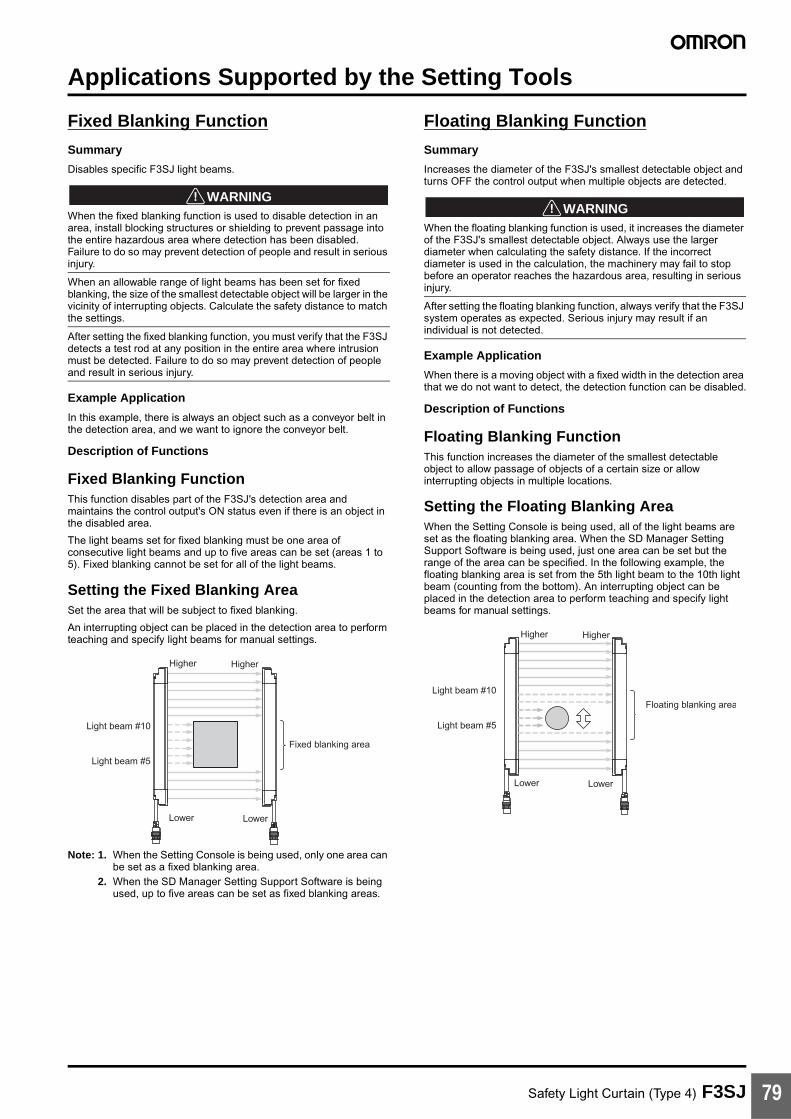
Safety Light Curtain (Type 4) F3SJ 79
Applications Supported by the Setting Tools
Fixed Blanking Function
Summary
Disables specific F3SJ light beams.
!WARNINGWhen the fixed blanking function is used to disable detection in an area, install blocking structures or shielding to prevent passage into the entire hazardous area where detection has been disabled.Failure to do so may prevent detection of people and result in serious injury.
When an allowable range of light beams has been set for fixed blanking, the size of the smallest detectable object will be larger in the vicinity of interrupting objects. Calculate the safety distance to match the settings.
After setting the fixed blanking function, you must verify that the F3SJ detects a test rod at any position in the entire area where intrusion must be detected. Failure to do so may prevent detection of people and result in serious injury.
Example Application
In this example, there is always an object such as a conveyor belt in the detection area, and we want to ignore the conveyor belt.
Description of Functions
Fixed Blanking FunctionThis function disables part of the F3SJ's detection area and maintains the control output's ON status even if there is an object in the disabled area.
The light beams set for fixed blanking must be one area of consecutive light beams and up to five areas can be set (areas 1 to 5). Fixed blanking cannot be set for all of the light beams.
Setting the Fixed Blanking AreaSet the area that will be subject to fixed blanking.
An interrupting object can be placed in the detection area to perform teaching and specify light beams for manual settings.
Note: 1. When the Setting Console is being used, only one area can be set as a fixed blanking area.
2. When the SD Manager Setting Support Software is being used, up to five areas can be set as fixed blanking areas.
Floating Blanking Function
Summary
Increases the diameter of the F3SJ's smallest detectable object and turns OFF the control output when multiple objects are detected.
!WARNINGWhen the floating blanking function is used, it increases the diameter of the F3SJ's smallest detectable object. Always use the larger diameter when calculating the safety distance. If the incorrect diameter is used in the calculation, the machinery may fail to stop before an operator reaches the hazardous area, resulting in serious injury.
After setting the floating blanking function, always verify that the F3SJ system operates as expected. Serious injury may result if an individual is not detected.
Example Application
When there is a moving object with a fixed width in the detection area that we do not want to detect, the detection function can be disabled.
Description of Functions
Floating Blanking FunctionThis function increases the diameter of the smallest detectable object to allow passage of objects of a certain size or allow interrupting objects in multiple locations.
Setting the Floating Blanking AreaWhen the Setting Console is being used, all of the light beams are set as the floating blanking area. When the SD Manager Setting Support Software is being used, just one area can be set but the range of the area can be specified. In the following example, the floating blanking area is set from the 5th light beam to the 10th light beam (counting from the bottom). An interrupting object can be placed in the detection area to perform teaching and specify light beams for manual settings.
Higher Higher
Lower Lower
Fixed blanking area
Light beam #10
Light beam #5
Floating blanking area
Higher Higher
Lower Lower
Light beam #10
Light beam #5
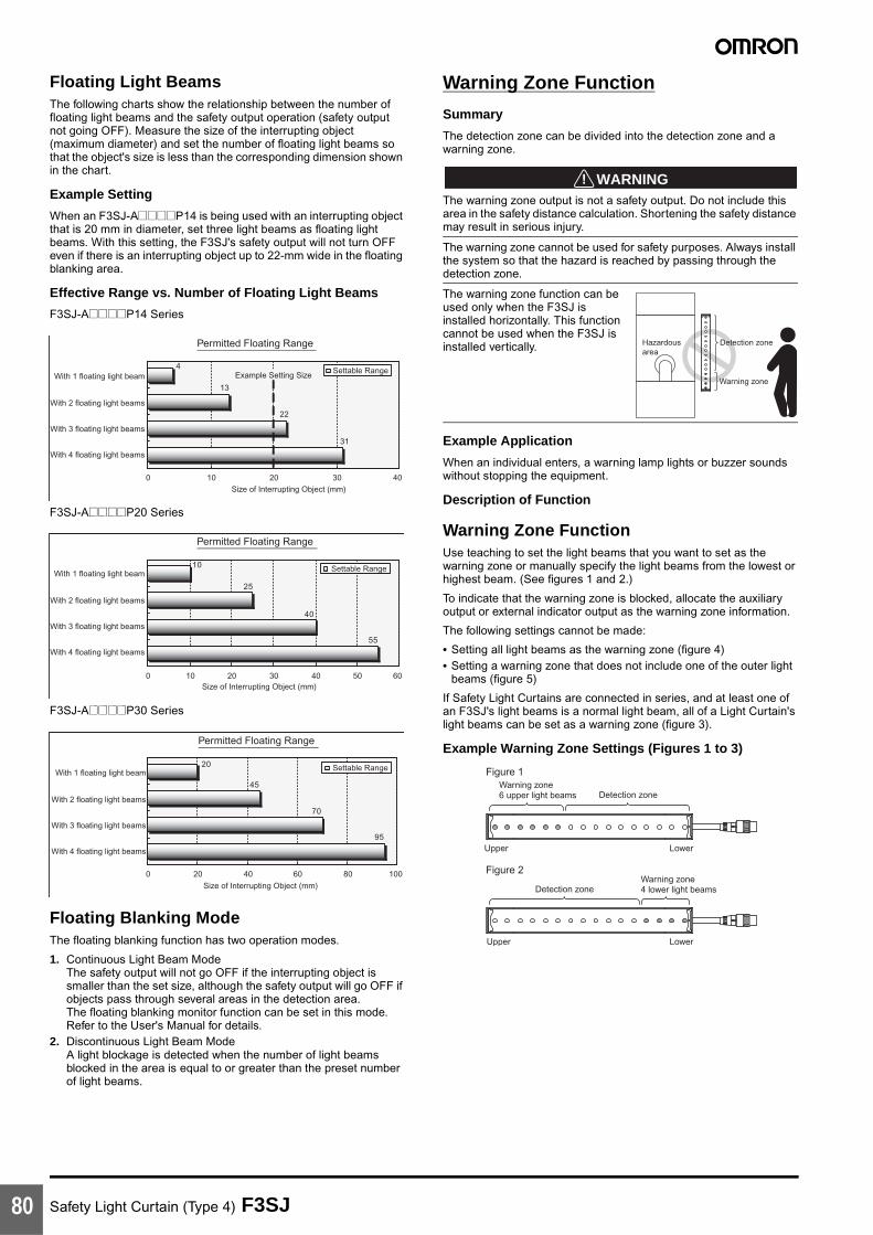
Safety Light Curtain (Type 4) F3SJ80
Floating Light BeamsThe following charts show the relationship between the number of floating light beams and the safety output operation (safety output not going OFF). Measure the size of the interrupting object (maximum diameter) and set the number of floating light beams so that the object's size is less than the corresponding dimension shown in the chart.
Example Setting
When an F3SJ-A@@@@P14 is being used with an interrupting object that is 20 mm in diameter, set three light beams as floating light beams. With this setting, the F3SJ's safety output will not turn OFF even if there is an interrupting object up to 22-mm wide in the floating blanking area.
Effective Range vs. Number of Floating Light Beams
F3SJ-A@@@@P14 Series
F3SJ-A@@@@P20 Series
F3SJ-A@@@@P30 Series
Floating Blanking ModeThe floating blanking function has two operation modes.
1. Continuous Light Beam ModeThe safety output will not go OFF if the interrupting object is smaller than the set size, although the safety output will go OFF if objects pass through several areas in the detection area.The floating blanking monitor function can be set in this mode. Refer to the User's Manual for details.
2. Discontinuous Light Beam ModeA light blockage is detected when the number of light beams blocked in the area is equal to or greater than the preset number of light beams.
Warning Zone Function
Summary
The detection zone can be divided into the detection zone and a warning zone.
!WARNINGThe warning zone output is not a safety output. Do not include this area in the safety distance calculation. Shortening the safety distance may result in serious injury.
The warning zone cannot be used for safety purposes. Always install the system so that the hazard is reached by passing through the detection zone.
The warning zone function can be used only when the F3SJ is installed horizontally. This function cannot be used when the F3SJ is installed vertically.
Example Application
When an individual enters, a warning lamp lights or buzzer sounds without stopping the equipment.
Description of Function
Warning Zone FunctionUse teaching to set the light beams that you want to set as the warning zone or manually specify the light beams from the lowest or highest beam. (See figures 1 and 2.)
To indicate that the warning zone is blocked, allocate the auxiliary output or external indicator output as the warning zone information.
The following settings cannot be made:
• Setting all light beams as the warning zone (figure 4)• Setting a warning zone that does not include one of the outer light
beams (figure 5)
If Safety Light Curtains are connected in series, and at least one of an F3SJ's light beams is a normal light beam, all of a Light Curtain's light beams can be set as a warning zone (figure 3).
Example Warning Zone Settings (Figures 1 to 3)
Permitted Floating Range
0 10 20 30 40
Settable Range4
13
22
31
Example Setting SizeWith 1 floating light beam
With 2 floating light beams
With 3 floating light beams
With 4 floating light beams
Size of Interrupting Object (mm)
0 10 20 30 40 50 60
10
40
25
55
Permitted Floating Range
Settable RangeWith 1 floating light beam
With 2 floating light beams
With 3 floating light beams
With 4 floating light beams
Size of Interrupting Object (mm)
0 20 40 60 80 100
20
45
70
95
Permitted Floating Range
Settable RangeWith 1 floating light beam
With 2 floating light beams
With 3 floating light beams
With 4 floating light beams
Size of Interrupting Object (mm)
Hazardous area
Detection zone
Warning zone
Lower
Warning zone 6 upper light beams Detection zone
Upper
LowerUpper
Warning zone4 lower light beamsDetection zone
Figure 1
Figure 2

Safety Light Curtain (Type 4) F3SJ 81
Examples of Unacceptable Warning Zone Settings (Figures 4 and 5)
Warning Zone Display LabelWhen the warning zone is set, affix this label to indicate which areas belong to the normal detection zone and the warning zone.
Muting Function
Summary
Makes settings related to the muting function.
!WARNINGThe muting function disables the safety functions of the device. Additional safety measures must be taken to ensure safety while this function is working.
Install muting sensors so that they can distinguish between the object that is being allowed to be pass through the detection zone and a person.
Muting lamps (external indicators) that indicate the status of the muting function must be installed where they are clearly visible to workers from all the operating positions.
Use two independent input devices for the muting inputs. (For the PNP output-type F3SJ, use a sensor with a PNP transistor output or N.O. contact. For the NPN output-type F3SJ, use a sensor with an NPN transistor output or N.O. type contact.)
To prevent a worker from entering the hazardous area while the muting function is engaged, install the F3SJ, muting sensor, and then a protective barrier and set a limited muting time.
Example Applications• Allowing only work pieces to pass into the conveyor entrance• Operating the muting function in a specific area only• Setting a different muting mode when standard muting is not
appropriate for the application
Description of Functions (See User's Manual for details.)
Operation ModesWhen the SD Manager Setting Support Software is being used, any one of the following three operation modes can be selected for the muting function.
1. Standard Muting ModeThis is the default operation mode, which is set when the F3SJ is shipped from the factory.The muting function is enabled by turning ON muting inputs 1 and 2 with a time lag.
Note: Settings such as the muting time limit value can be changed.2. Specialized Exit Muting Mode (Can be set with the SD Manager
Setting Support Software only.)The muting function is enabled by turning ON muting inputs 1 and 2 with a time lag.Installation of the muting input sensors is simpler than standard mode because the Safety Light Curtain's blocked light status is used to end muting.
3. Position Detection Muting Mode (Can be set with the SD Manager Setting Support Software only.)Sensors such as limit switches are used for the muting inputs and the muting function is enabled by turning muting input from OFF to ON and then turning muting input 2 from ON to OFF within time difference T1 max. Use hybrid redundant inputs such as a combination of an N.O. contact input and an N.C. contact input. (When using a PNP-output photoelectric switch, use L/ON operation on one side and D/ON operation on the other side.)This mode is useful when you want to disable the F3SJ temporarily, such as when a person is placing an object at the conveyor entrance.
Partial Muting (Muting area) SettingsThe light beams controlled by the muting function can be specified with a setting tool. (When the F3SJ is shipped, all light beams are set.)
The light beams can be specified by teaching/recording the blocked light beams as muting light beams or manually specifying the desired light beams.
Lower
Upper
2CH
LowerUpper 1CH
Detection zoneAll light beams
Warning zoneAll light beams
Figure 3
LowerUpper
All light beams Warning zone
Figure 4
Figure 5
Upper Lower
Detection zone Warning zone Detection zone
Normal light beam Warning light beam
Warning zoneDetection zone
DETECTIONZONE
WARNINGZONE
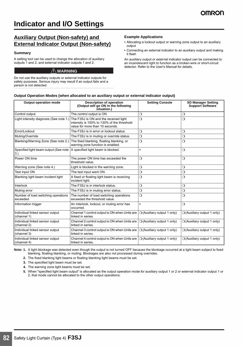
Safety Light Curtain (Type 4) F3SJ82
Indicator and I/O Settings
Auxiliary Output (Non-safety) and External Indicator Output (Non-safety)
Summary
A setting tool can be used to change the allocation of auxiliary outputs 1 and 2, and external indicator outputs 1 and 2.
!WARNING
Do not use the auxiliary outputs or external indicator outputs for safety purposes. Serious injury may result if an output fails and a person is not detected.
Example Applications• Allocating a lockout output or warning zone output to an auxiliary
output• Connecting an external indicator to an auxiliary output and making
it flash
An auxiliary output or external indicator output can be connected to an incandescent light to function as a broken-wire or short-circuit detector. Refer to the User's Manual for details.
Output Operation Modes (when allocated to an auxiliary output or external indicator output)
Note: 1. A light blockage was detected even though the output is not turned OFF because the blockage occurred at a light beam subject to fixed blanking, floating blanking, or muting. Blockages are also not processed during overrides.
2. The fixed blanking light beams or floating blanking light beams must be set.3. The specified light beam must be set.4. The warning zone light beams must be set.5. When "specified light beam output" is allocated as the output operation mode for auxiliary output 1 or 2 or external indicator output 1 or
2, that mode cannot be allocated to the other output operations.
Output operation mode Description of operation(Output will go ON in the following
situation.)
Setting Console SD Manager Setting Support Software
Control output The control output is ON
Light intensity diagnosis (See note 1.) The F3SJ is ON and the received light intensity is 100% to 130% of the threshold value for more than 10 seconds.
Error/Lockout The F3SJ is in error or lockout status.
Muting/Override The F3SJ is in muting or override status.
Blanking/Warning Zone (See note 2.) The fixed blanking, floating blanking, or warning zone function is enabled.
Specified light beam output (See note 3.)
A specified light beam is blocked. ×
Power ON time The power ON time has exceeded the threshold value.
Warning zone (See note 4.) Light is blocked in the warning zone.
Test input ON The test input went ON.
Blanking light beam incident light A fixed or floating light beam is receiving incident light.
Interlock The F3SJ is in interlock status.
Muting error The F3SJ is in muting error status.
Number of load switching operations exceeded
The number of load switching operations exceeded the threshold value.
Information trigger An interlock, lockout, or muting error has occurred.
×
Individual linked sensor output (channel 1)
Channel 1 control output is ON when Units are linked in series.
(Auxiliary output 1 only) (Auxiliary output 1 only)
Individual linked sensor output (channel 2)
Channel 2 control output is ON when Units are linked in series.
(Auxiliary output 1 only) (Auxiliary output 1 only)
Individual linked sensor output (channel 3)
Channel 3 control output is ON when Units are linked in series.
(Auxiliary output 1 only) (Auxiliary output 1 only)
Individual linked sensor output (channel 4)
Channel 4 control output is ON when Units are linked in series.
(Auxiliary output 1 only) (Auxiliary output 1 only)

Safety Light Curtain (Type 4) F3SJ 83
Changing the Detection Distance
Change detection distance function
Summary
The F3SJ's detection distance can be shortened.
Example Application
The F3SJ's detection distance can be shortened to avoid affecting other photoelectric sensors.
When devices are installed close together, shortening the detection distance can reduce mutual interference.
Description of Function
The detection distance can be set to 0.5 m, 1 m, 2 m, 3 m, 5 m, or MAX (either 7 m or 9 m).
The most suitable detection distance can be set to match the installation distance.
Note: MAX represents the rated detection distance.
Monitoring Operation
Received Light Intensity Indicator
Summary
It is possible to read the F3SJ's received light intensity.
Example Application
Adjust the light beams while checking the F3SJ's received light intensity.
Description of Function
Indicates the F3SJ's received light intensity.
The F3SJ's received light intensity level can be checked with a setting tool.
Ambient Light Intensity Indicator
Summary
It is possible to read the intensity of the light received by the F3SJ from ambient sources, such as other photoelectric sensors.
Example Application
Display the ambient light level while taking steps to reduce light interference form sources such as photoelectric switches in the area and neighboring F3SJ Units.
Description of Function
Indicates the ambient light level at the F3SJ from other light sources such as photoelectric sensors.
This function can help identify the photoelectric sensors that are the source of the light interference and identify the light beams being affected by the ambient light.
Other FunctionsThe F3SJ is also equipped with the following functions.
Refer to the User's Manual for details on using these functions.
• Status indicators• Error log• Power ON time• Number of load switching operations• Safety distance calculation function• Power cable length calculation function• Rated response time check function

MEMO (This page was intentionally left blank.)
Safety Light Curtain (Type 4) F3SJ84

MEMO(This page was intentionally left blank.)
Safety Light Curtain (Type 4) F3SJ 85

MEMO (This page was intentionally left blank.)
Safety Light Curtain (Type 4) F3SJ86

Terms and Conditions of Sale1. Offer; Acceptance. These terms and conditions (these "Terms") are deemed
part of all quotes, agreements, purchase orders, acknowledgments, price lists,catalogs, manuals, brochures and other documents, whether electronic or inwriting, relating to the sale of products or services (collectively, the "Products")by Omron Electronics LLC and its subsidiary companies (“Omron”). Omronobjects to any terms or conditions proposed in Buyer’s purchase order or otherdocuments which are inconsistent with, or in addition to, these Terms.
2. Prices; Payment Terms. All prices stated are current, subject to change with-out notice by Omron. Omron reserves the right to increase or decrease priceson any unshipped portions of outstanding orders. Payments for Products aredue net 30 days unless otherwise stated in the invoice.
3. Discounts. Cash discounts, if any, will apply only on the net amount of invoicessent to Buyer after deducting transportation charges, taxes and duties, and willbe allowed only if (i) the invoice is paid according to Omron’s payment termsand (ii) Buyer has no past due amounts.
4. Interest. Omron, at its option, may charge Buyer 1-1/2% interest per month orthe maximum legal rate, whichever is less, on any balance not paid within thestated terms.
5. Orders. Omron will accept no order less than $200 net billing. 6. Governmental Approvals. Buyer shall be responsible for, and shall bear all
costs involved in, obtaining any government approvals required for the impor-tation or sale of the Products.
7. Taxes. All taxes, duties and other governmental charges (other than generalreal property and income taxes), including any interest or penalties thereon,imposed directly or indirectly on Omron or required to be collected directly orindirectly by Omron for the manufacture, production, sale, delivery, importa-tion, consumption or use of the Products sold hereunder (including customsduties and sales, excise, use, turnover and license taxes) shall be charged toand remitted by Buyer to Omron.
8. Financial. If the financial position of Buyer at any time becomes unsatisfactoryto Omron, Omron reserves the right to stop shipments or require satisfactorysecurity or payment in advance. If Buyer fails to make payment or otherwisecomply with these Terms or any related agreement, Omron may (without liabil-ity and in addition to other remedies) cancel any unshipped portion of Prod-ucts sold hereunder and stop any Products in transit until Buyer pays allamounts, including amounts payable hereunder, whether or not then due,which are owing to it by Buyer. Buyer shall in any event remain liable for allunpaid accounts.
9. Cancellation; Etc. Orders are not subject to rescheduling or cancellationunless Buyer indemnifies Omron against all related costs or expenses.
10. Force Majeure. Omron shall not be liable for any delay or failure in deliveryresulting from causes beyond its control, including earthquakes, fires, floods,strikes or other labor disputes, shortage of labor or materials, accidents tomachinery, acts of sabotage, riots, delay in or lack of transportation or therequirements of any government authority.
11. Shipping; Delivery. Unless otherwise expressly agreed in writing by Omron:a. Shipments shall be by a carrier selected by Omron; Omron will not drop ship
except in “break down” situations.b. Such carrier shall act as the agent of Buyer and delivery to such carrier shall
constitute delivery to Buyer;c. All sales and shipments of Products shall be FOB shipping point (unless oth-
erwise stated in writing by Omron), at which point title and risk of loss shallpass from Omron to Buyer; provided that Omron shall retain a security inter-est in the Products until the full purchase price is paid;
d. Delivery and shipping dates are estimates only; ande. Omron will package Products as it deems proper for protection against nor-
mal handling and extra charges apply to special conditions.12. Claims. Any claim by Buyer against Omron for shortage or damage to the
Products occurring before delivery to the carrier must be presented in writingto Omron within 30 days of receipt of shipment and include the original trans-portation bill signed by the carrier noting that the carrier received the Productsfrom Omron in the condition claimed.
13. Warranties. (a) Exclusive Warranty. Omron’s exclusive warranty is that theProducts will be free from defects in materials and workmanship for a period oftwelve months from the date of sale by Omron (or such other period expressedin writing by Omron). Omron disclaims all other warranties, express or implied.(b) Limitations. OMRON MAKES NO WARRANTY OR REPRESENTATION,EXPRESS OR IMPLIED, ABOUT NON-INFRINGEMENT, MERCHANTABIL-
ITY OR FITNESS FOR A PARTICULAR PURPOSE OF THE PRODUCTS.BUYER ACKNOWLEDGES THAT IT ALONE HAS DETERMINED THAT THEPRODUCTS WILL SUITABLY MEET THE REQUIREMENTS OF THEIRINTENDED USE. Omron further disclaims all warranties and responsibility ofany type for claims or expenses based on infringement by the Products or oth-erwise of any intellectual property right. (c) Buyer Remedy. Omron’s sole obli-gation hereunder shall be, at Omron’s election, to (i) replace (in the formoriginally shipped with Buyer responsible for labor charges for removal orreplacement thereof) the non-complying Product, (ii) repair the non-complyingProduct, or (iii) repay or credit Buyer an amount equal to the purchase price ofthe non-complying Product; provided that in no event shall Omron be responsi-ble for warranty, repair, indemnity or any other claims or expenses regardingthe Products unless Omron’s analysis confirms that the Products were prop-erly handled, stored, installed and maintained and not subject to contamina-tion, abuse, misuse or inappropriate modification. Return of any Products byBuyer must be approved in writing by Omron before shipment. Omron Compa-nies shall not be liable for the suitability or unsuitability or the results from theuse of Products in combination with any electrical or electronic components,circuits, system assemblies or any other materials or substances or environ-ments. Any advice, recommendations or information given orally or in writing,are not to be construed as an amendment or addition to the above warranty.See http://oeweb.omron.com or contact your Omron representative for pub-lished information.
14. Limitation on Liability; Etc. OMRON COMPANIES SHALL NOT BE LIABLEFOR SPECIAL, INDIRECT, INCIDENTAL, OR CONSEQUENTIAL DAMAGES,LOSS OF PROFITS OR PRODUCTION OR COMMERCIAL LOSS IN ANYWAY CONNECTED WITH THE PRODUCTS, WHETHER SUCH CLAIM ISBASED IN CONTRACT, WARRANTY, NEGLIGENCE OR STRICT LIABILITY.Further, in no event shall liability of Omron Companies exceed the individualprice of the Product on which liability is asserted.
15. Indemnities. Buyer shall indemnify and hold harmless Omron Companies andtheir employees from and against all liabilities, losses, claims, costs andexpenses (including attorney's fees and expenses) related to any claim, inves-tigation, litigation or proceeding (whether or not Omron is a party) which arisesor is alleged to arise from Buyer's acts or omissions under these Terms or inany way with respect to the Products. Without limiting the foregoing, Buyer (atits own expense) shall indemnify and hold harmless Omron and defend or set-tle any action brought against such Companies to the extent based on a claimthat any Product made to Buyer specifications infringed intellectual propertyrights of another party.
16. Property; Confidentiality. Any intellectual property in the Products is the exclu-sive property of Omron Companies and Buyer shall not attempt to duplicate itin any way without the written permission of Omron. Notwithstanding anycharges to Buyer for engineering or tooling, all engineering and tooling shallremain the exclusive property of Omron. All information and materials suppliedby Omron to Buyer relating to the Products are confidential and proprietary,and Buyer shall limit distribution thereof to its trusted employees and strictlyprevent disclosure to any third party.
17. Export Controls. Buyer shall comply with all applicable laws, regulations andlicenses regarding (i) export of products or information; (iii) sale of products to“forbidden” or other proscribed persons; and (ii) disclosure to non-citizens ofregulated technology or information.
18. Miscellaneous. (a) Waiver. No failure or delay by Omron in exercising any rightand no course of dealing between Buyer and Omron shall operate as a waiverof rights by Omron. (b) Assignment. Buyer may not assign its rights hereunderwithout Omron's written consent. (c) Law. These Terms are governed by thelaw of the jurisdiction of the home office of the Omron company from whichBuyer is purchasing the Products (without regard to conflict of law princi-ples). (d) Amendment. These Terms constitute the entire agreement betweenBuyer and Omron relating to the Products, and no provision may be changedor waived unless in writing signed by the parties. (e) Severability. If any provi-sion hereof is rendered ineffective or invalid, such provision shall not invalidateany other provision. (f) Setoff. Buyer shall have no right to set off any amountsagainst the amount owing in respect of this invoice. (g) Definitions. As usedherein, “including” means “including without limitation”; and “Omron Compa-nies” (or similar words) mean Omron Corporation and any direct or indirectsubsidiary or affiliate thereof.
Certain Precautions on Specifications and Use1. Suitability of Use. Omron Companies shall not be responsible for conformity
with any standards, codes or regulations which apply to the combination of theProduct in the Buyer’s application or use of the Product. At Buyer’s request,Omron will provide applicable third party certification documents identifyingratings and limitations of use which apply to the Product. This information byitself is not sufficient for a complete determination of the suitability of the Prod-uct in combination with the end product, machine, system, or other applicationor use. Buyer shall be solely responsible for determining appropriateness ofthe particular Product with respect to Buyer’s application, product or system.Buyer shall take application responsibility in all cases but the following is anon-exhaustive list of applications for which particular attention must be given:(i) Outdoor use, uses involving potential chemical contamination or electricalinterference, or conditions or uses not described in this document.(ii) Use in consumer products or any use in significant quantities. (iii) Energy control systems, combustion systems, railroad systems, aviationsystems, medical equipment, amusement machines, vehicles, safety equip-ment, and installations subject to separate industry or government regulations. (iv) Systems, machines and equipment that could present a risk to life or prop-erty. Please know and observe all prohibitions of use applicable to this Prod-uct. NEVER USE THE PRODUCT FOR AN APPLICATION INVOLVING SERIOUSRISK TO LIFE OR PROPERTY OR IN LARGE QUANTITIES WITHOUTENSURING THAT THE SYSTEM AS A WHOLE HAS BEEN DESIGNED TO
ADDRESS THE RISKS, AND THAT THE OMRON’S PRODUCT IS PROP-ERLY RATED AND INSTALLED FOR THE INTENDED USE WITHIN THEOVERALL EQUIPMENT OR SYSTEM.
2. Programmable Products. Omron Companies shall not be responsible for theuser’s programming of a programmable Product, or any consequence thereof.
3. Performance Data. Data presented in Omron Company websites, catalogsand other materials is provided as a guide for the user in determining suitabil-ity and does not constitute a warranty. It may represent the result of Omron’stest conditions, and the user must correlate it to actual application require-ments. Actual performance is subject to the Omron’s Warranty and Limitationsof Liability.
4. Change in Specifications. Product specifications and accessories may bechanged at any time based on improvements and other reasons. It is our prac-tice to change part numbers when published ratings or features are changed,or when significant construction changes are made. However, some specifica-tions of the Product may be changed without any notice. When in doubt, spe-cial part numbers may be assigned to fix or establish key specifications foryour application. Please consult with your Omron’s representative at any timeto confirm actual specifications of purchased Product.
5. Errors and Omissions. Information presented by Omron Companies has beenchecked and is believed to be accurate; however, no responsibility is assumedfor clerical, typographical or proofreading errors or omissions.
$%"=GG<"=GGG ("=GG
Cat. No. F074-E1-04 8/06 Specifications subject to change without notice Printed in USA
! "#992; # !;*2F9
$%&'&&$&(
( -# %!7'415,
$)$*)+,,6< 3 =
,,((&&)&&
- ./ 012
111# # 3H/- 2.2"/4#
!56 ## !%11,:,5# !%11,25


