On Cognitive Robot Woodworking in SMErobotics Haage, Mathias; Profanter, Stefan; Kessler, Ingmar; Perzylo, Alexander; Somani, Nikhil; Sörnmo, Olof; Karlsson, Martin; Robertz, Sven; Nilsson, Klas; Resch, Ludovic; Marti, Michael Published in: 47th International Symposium on Robotics, ISR 2016 2016 Document Version: Publisher's PDF, also known as Version of record Link to publication Citation for published version (APA): Haage, M., Profanter, S., Kessler, I., Perzylo, A., Somani, N., Sörnmo, O., Karlsson, M., Robertz, S., Nilsson, K., Resch, L., & Marti, M. (2016). On Cognitive Robot Woodworking in SMErobotics. In 47th International Symposium on Robotics, ISR 2016 (pp. 521-527). VDE Verlag gmbh Berlin. Total number of authors: 11 General rights Unless other specific re-use rights are stated the following general rights apply: Copyright and moral rights for the publications made accessible in the public portal are retained by the authors and/or other copyright owners and it is a condition of accessing publications that users recognise and abide by the legal requirements associated with these rights. • Users may download and print one copy of any publication from the public portal for the purpose of private study or research. • You may not further distribute the material or use it for any profit-making activity or commercial gain • You may freely distribute the URL identifying the publication in the public portal Read more about Creative commons licenses: https://creativecommons.org/licenses/ Take down policy If you believe that this document breaches copyright please contact us providing details, and we will remove access to the work immediately and investigate your claim. Download date: 18. Jan. 2022
Document Version:Publisher's PDF, also known as Version of record
Link to publication
Citation for published version (APA):Haage, M., Profanter, S., Kessler, I., Perzylo, A., Somani, N., Sörnmo, O., Karlsson, M., Robertz, S., Nilsson, K.,Resch, L., & Marti, M. (2016). On Cognitive Robot Woodworking in SMErobotics. In 47th InternationalSymposium on Robotics, ISR 2016 (pp. 521-527). VDE Verlag gmbh Berlin.
Total number of authors:11
General rightsUnless other specific re-use rights are stated the following general rights apply:Copyright and moral rights for the publications made accessible in the public portal are retained by the authorsand/or other copyright owners and it is a condition of accessing publications that users recognise and abide by thelegal requirements associated with these rights. • Users may download and print one copy of any publication from the public portal for the purpose of private studyor research. • You may not further distribute the material or use it for any profit-making activity or commercial gain • You may freely distribute the URL identifying the publication in the public portal
Read more about Creative commons licenses: https://creativecommons.org/licenses/Take down policyIf you believe that this document breaches copyright please contact us providing details, and we will removeaccess to the work immediately and investigate your claim.
This paper details and discusses work performed at the woodworking SME Mivelaz Techniques Bois SA within the SME-robotics FP7 project. The aim is to improve non-expert handling of the cell by introduction of cognitive abilities in therobot system. Three areas are considered; intuitive programming, process adaptation and system integration. Proposedcognitive components are described together with experiments performed.
1 IntroductionToday’s robot systems have limits in their ability to dealwith frequent changes in the manufacturing process. Whilerobots are able to carry out repetitive tasks to a highstandard, they do not meet the demands of small- andmedium-sized enterprises (SMEs); small lot sizes, highnumber of product variants, frequent re-configuration andre-programming, and little or no in-house robot exper-tise. Also, for the setup and operation of robot systemsin an SME environment, which is typically less structuredand involves more uncertainties than large-scale or mass-production industries, the currently available solutions re-sult in overly complex system integration.The SMErobotics1 project vision is to significantly lowerthe threshold for introducing and meeting productivity de-mands with robot automation on the SME shop floor. Cog-nitive abilities need to be included per default in the robotsystem to aid the operator in setup and during process withlittle or no robot expertise needed. To this end, robot sys-tem components and techniques are defined to target sev-eral aspects of SME robot automation, such as human-robot interaction, system integration and process adapta-tion. Together the components present cognitive ”add-ons”to an industrial robot system.In this paper a SME robot cell set in the woodworking do-main is targeted by a selection of SMErobotics techniques.The production cell is located at Mivelaz Techniques BoisSA, an SME located in Switzerland that manufactures pre-
1http://www.smerobotics.org
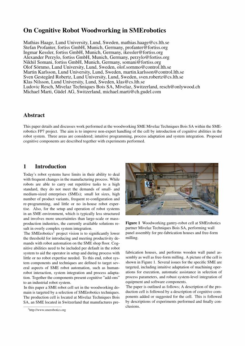
Figure 1 Woodworking gantry-robot cell at SMEroboticspartner Mivelaz Techniques Bois SA, performing wallpanel assembly for pre-fabrication houses and free-formmilling.
fabrication houses, and performs wooden wall panel as-sembly as well as free-form milling. A picture of the cell isshown in Figure 1. Several issues for the specific SME aretargeted, including intuitive adaptation of machining oper-ations for execution, automatic assistance in selection ofprocess parameters, and robust system-level integration ofequipment and software components.The paper is outlined as follows; A description of the pro-duction cell is followed by a description of cognitive com-ponents added or suggested for the cell. This is followedby descriptions of experiments performed and finally con-clusions.
(a) Wall struts are manufactured by CNC.
(b) Struts are manually assembled into wall structures.
(c) Panels are assembled and fitted to wall structures using the gantryrobot cell.
Figure 2 The basic shop floor production flow at theSME.
2 Robot Woodworking in an SMEThis section describes the woodworking robot cell locatedat Mivelaz Techniques Bois SA. The SME produces one-off pre-fabrication houses based on in-house CAD/CAM2
expertise. The on-site shop floor manufactures the requiredhouse parts (walls and other details) that are then shippedfor assembly at the customer site.The gantry robot3 cell is part of a production flow thatstarts with CAD/CAM resulting in machining descriptionformats and blueprints for the shop floor, followed by ma-chining and assembly operations on the shop floor. Themajor production steps are depicted in Figure 2. CNC4 ma-chines manufacture struts that are manually assembled intowall structures. These are then moved onto the gantry robotwork table where panel assembly is taking place. Addi-tional operations, such as quality inspection, adding insu-lation material, or turning the wall structure for panel as-sembly on the opposite side, is performed manually.An assembly consists of picking panels and placing thema side of the wall structure. This is usually followed by
2Computer Aided Design/Manufacturing3The gantry has 6 degrees of freedom. Panel assembly utilizes five
while free-form milling uses all six DoFs.4Computerized Numerical Control
(a) Pick and place of panels.
(b) Nailing of panels to wall structure.
(c) Sawing of panels to fit wall structure.
Figure 3 Gantry wood panel operations utilized for thepanel assembly in Figure 2(c).
nailing of panels to the structure and concluded by saw-ing and milling the panels to fit the structure. Since woodis a live material, fitting is usually performed by materialremoval according to nominal CAD dimensions (with anadded fault-tolerance offset) followed by manual adjust-ment of the sawing and milling operation and re-executionfor exact fit. The gantry robot has two work zones to allowseveral walls to be assembled at the same time for higherthroughput.
2.1 IssuesAiming for non-expert handling, interviews revealed de-pendencies on in-house robot and robot-related expertise:
• General robot expertise is needed from time to time(estimated once per two weeks) to solve issues thatare beyond the knowledge of an ordinary robot oper-ator. Typically this amounts to resolving issues withCAMed machining operations on the shop floor.
• Process adaptation due to tool wear is currently donemanually, requiring operator process experience.
• Introduction of new sensors and other hardware equip-ment requires PLC expertise and experience in thecurrent cell setup.
3 System ArchitectureAs a step towards addressing the issues listed in Sec-tion 2.1, cognitive software components and techniquesfrom three SMErobotics areas were adopted for the cell;intuitive programming, sensor adaptation and system-levelintegration. The added software was physically hosted ona PC during experiments, but in preparation for permanentinstallation of part of the software an industrial PC was alsointegrated in the cell setup.Figure 4 shows an architectural overview for the introduc-tion of cognitive components in the robot system; Intu-itive programming is represented by several of the com-ponents. Process adaptation is listed as a component, but atthe moment of writing actual packaging of the adaptationsoftware as a component has not been performed. Finally,system-level integration is concerned with interoperabilityof equipment and software components and is representedin (some) of the arrows in the figure. Robot operations arestored in a woodworking shop floor format called BTL andare imported to a database. The operations then need to beselected, possibly changed and annotated with further pro-cess data. This is done using the interaction manager withassociated GUI. The task execution engine allows visual-ization of operations through a generic simulation environ-ment, as well as generation and deployment of robot pro-grams, and monitoring of a running task. Two deploymenttargets are available in the system, a robot-specific simu-lation environment (ABB RobotStudio5) capable of exe-cuting the generated robot program and the physical con-troller. During execution sensor data is collected for pro-cess adaptation. Task execution is a matter of interactingwith both the cell PLC and the robot controller. This isdone by communicating with the PLC through the robotprogram.The implemented architecture is more complicated thanthe architecture described so far. Since components wereadapted from different project partners from existing solu-tions it resulted in incompatibilities that needed to be re-solved for components to interoperate. Incompatibilitiessuch as differing data structures and execution environ-ments motivated an investigation into and application of(some) SMErobotics system-level integration techniques.
3.1 BTL parserBTL6 is an open data format mainly maintained by Ligno-cam7. It was created by two CAD companies, SEMA8 andCADWORK9. It is a data transfer format for wood con-structions containing both part geometries and machiningoperations which is understood by woodworking CNC ma-chines. As an example, the geometry in Figure 2 is part ofa house described in one BTL file. The dark areas in Fig-ure 2(a) represent material removal operations, the red box
Figure 4 Proposed architecture for the introduction ofcognitive components in the woodworking robot system.
in 2(b) indicate a selected strut, and the red line in 2(c)represents a sawing operation. Since solutions for BTLinterpretation for industrial robots were scarce during theproject, it was necessary to develop a BTL industrial robotcomponent specifically for the SME need10. The compo-nent is used to make BTL data accessible to the other com-ponents in the system.
3.2 Intuitive Adaptation of BTL processesAs part of SMErobotics several components were devel-oped to make robot automation accessible to non-expertrobot operators. Operators are experts in their respectivedomains and should be able to communicate their inten-tions to the system, without being experts in robotics. Inthe interaction manager, this is done by explicitly model-ing the required knowledge in a way, such that the robotsystem is able to understand the language of the domain ex-pert. A semantic description language has been developedto specify processes, interaction objects, and the workcellsin which the processes shall be executed [3, 4]. For in-teraction, an intuitive touch interface serves as the primarymodality for inspecting and parameterizing manufacturingprocesses. This interface serves as a frontend to the seman-tic process description. For the woodworking applicationthe interaction manager was adopted to read the BTL de-scription through a semantic transformation to the processdescription language. It then manages the dialogue withthe robot operator, assisting in decision making and faultdiagnosis of BTL execution. It assists in task-level pro-gramming and configuration of the BTL process and worksin close co-operation with the task execution engine. To-gether the two components aim at providing an intuitiveapproach to programming and execution in the SME robotsystem.
3.3 Task Execution and MonitoringThe output of the BTL parser (Section 3.1) and the intu-itive instruction GUI (Section 3.2, [6]) is an object-centrictask description which can not be executed directly by therobot. E.g., a BTL command defines a sawing line on an
10BTL for industrial robots will kindly be supported and availablethrough Cognibotics, http://www.cognibotics.com/
object, but not the corresponding coordinates in the baseframe of the robot. The description has to be mapped ac-cordingly and a robot program has to be generated usingthe task execution engine to execute the desired steps.The task execution engine checks all preconditions for eachtask and maps an abstract task description to one or morespecific commands, called skills. For this mapping differ-ent sensor values and additional data is required, e.g., therelative position of the workpiece to the robot has to bemeasured and the task parameters adapted to match the off-set pose. After all the mappings are calculated and the pro-cess is ready to be executed, the generated program can bedeployed to, and simulated within the ABB Robot Studiosimulation environment. After successful simulation, theprogram can be sent directly to the robot for execution.The task execution engine also performs monitoring. Inorder to make robots more viable in SMEs, not only theirinstruction and normal operation need to be more intuitivebut also their operation when errors occur, because it can-not be expected that there is always an expert on site toresolve them. Errors are detected by equipping the robotsystem with additional sensors and detecting when an exe-cution no longer produces the expected sensor values. Byperforming the error detection and handling on the tasklevel, the robot system knows the expected sensor valuesand how to handle potential errors. This error handlingcan be automatic or it can include the shop floor worker.In the latter case, a semantically meaningful and human-understandable error message is shown to the worker in theuser interface. The worker is given a description of theerror and the initial, automatic actions taken by the robot(such as pausing of all movements), a recommendation onhow to resolve the error and several options for command-ing the robot system on how to proceed afterwards. Taskscan not only include a semantic description of the normalexecution of the task, but also descriptions of how to re-cover from certain types of errors, e.g., by simply repeatinga task.
3.4 Process AdaptationAutomatic or semi-automatic process adaptation may im-prove quality and lower the cognitive burden on the opera-tor by providing assistance in optimal selection of processparameters. The example found in the SME was adaptionof path speed during sawing which in this case was donemanually based on listening on the sound of the cuts andadjusting speed according to the experience of the opera-tor. Tool wear such as bluntness of the sawing blade arean example of important process parameters that are usu-ally not part of task programming unless automatic meansfor estimation are available. For comparison, classifiersfor several sensors were developed, including audio, ac-celerometer and robot joint torques. From a cost perspec-tive torque data is already available in the system. Audioprovides cheap but potentially noisy sensing. Accelerom-eter data is accurate but is also the most expensive inputmodality.
3.5 InteroperabilityFor simple setup, a robot system must be robust and flex-ible in integration of new equipment and software. TheSMErobotics project therefore offers a number of tools of-fering support for integration at the system level. At thecore, the basic communication channel between devicesand software components is proposed to be enhanced within-band syntactic and semantic descriptions for the channelto become self-describing.Self-describing data channels may give a human operatorearly and precise information about incompatibilities dur-ing set-up. Thus, they provide robustness against uninten-tional changes to interfaces and assist the human in identi-fying and fixing mistakes. It also allows to detect and han-dle mismatches in communication between equipment andsoftware from different vendors, which is often importantin an SME setting. It enables (semi-)automatic generationof communication bridges that connect incompatible de-vices. This is exemplified in [2], which generates bridgesfor the case of semantically compatible but structurally dif-ferent message formats, such as between ROS and Lab-Comm. The message translation can be either manuallyspecified, or automatically deduced from semantic descrip-tions, or a combination of the two. In the SME semi-automatic bridge building is used for transforming mes-sages between the BTL parser and the process descriptionlanguage used by the interaction manager. Other potentialuses include assistance in PLC and sensor integration.A prototype protocol called LabComm11 is being devel-oped [1]. LabComm is an example of an in-band, self-describing protocol12 and is used to illustrate features oflow-level data channels, and how they can be used to bridgeand mitigate differences. LabComm ensures stable identi-ties/signatures of different message types on communica-tion channels. This can, for instance, be utilized for se-mantic grounding of messages towards external resources.In turn it allows the receiver of messages to verify that theset of messages the other party may send is precisely theones expected. In other words, any change to a messageformat, or addition of a new message type, is detected be-fore operation commences. Several tests were performedto evaluate LabComm in the SME context. Since compo-nents existed in two different execution contexts, ROS13
and OSGi14, LabComm was used to create communicationbridges between these. Also, since the communication be-tween the task execution engine and the robot controllerwas untyped, LabComm was used to create a typed and se-mantically grounded controller communication channel.Self-describing data has seen much use in web-service sys-tems, with protocols like Apache Avro15 and Google Proto-
11http://www.control.lth.se/Research/tools.html12Each time a communication channel is established between two de-
vices, a signature, describing all messages that can be transmitted on thechannel, is transmitted before the transmission of data begins.
col Buffers16. Systems for automation and motion control,on the other hand, tend to rely on standards (e.g., CANopendevice profiles). In line with the open-world assumption,we use self-describing data to make it possible to bridgeincompatibilities in order to enable agile setup and recon-figuration. An important difference between the LabCommself-describing data channels and systems like Avro is thatLabComm focuses on stability, requiring exactly matchingsignatures, whereas Avro supports schema evolution withmechanisms for automatic handling of added, removed, ormodified fields.In business and web-service applications,supporting such evolution is valueable, but in robot con-trol, stability and safety is paramount.
4 ExperimentsA number of experiments were performed on the industrialworkcell from Figure 1 which are described below.
4.1 Assembly of wooden house wallsThe main experiment consisted of evaluating the full soft-ware stack of our Cognitive System Architecture and hard-ware functionalities. For this task a simple wooden housewall was constructed (see Figure 5) using CADWORK andthen exported as a BTL file. The operations within the BTLinclude placing two panels, nailing and fixating them on awoooden frame, and cutting off overlapping parts of biggerpanels using a circular saw attached to the robot.
Figure 5 A simple wooden house wall with two panelswhich need to be placed, nailed, and sawed.
As depicted in Figure 4 different components are integratedinto the system and play different roles. This experimentwas carried out to prove that all the components work asexpected. The BTL interpreter (Section 3.1) is used to in-terpret the file generated by CADWORK, and to store itwithin the semantic storage (Section 3.2). After the fileis successfully parsed, it can be visualized in the intuitiveGUI (Figure 6).This intuitive GUI supports different input modalities fordifferent parameter types [5]. If necessary, task parame-ters can be modified (e.g., place-positions of the panels orlength and speed for a sawing line). When the process isready to be executed, it is passed to the interaction managerand task execution engine (Section 3.3). After all task pa-rameters are mapped to the corresponding robot skills, the
16https://developers.google.com/protocol-buffers
Figure 6 Woodworking process parsed from BTL andvisualized in the intuitive instruction GUI. Parameters foreach task can be modified before execution.
process can be simulated in ABB Robot Studio. For com-munication between different subsystems we use the inter-operability approach as described in Section 3.5. As soonas the simulation completed, the shopfloor-worker can de-cide to execute the process on the real robot (Figure 3).During execution, the interaction manager is monitoringdifferent system parameters to detect anomalies and to no-tify the worker if necessary (Section 3.3).
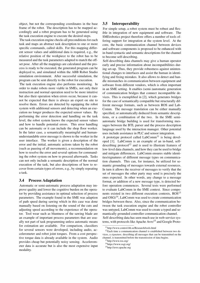
4.2 Automatic assessment of tool wearTo gather data for the audio-based classifier, cuts weremade under different conditions while the sound wasrecorded using a microphone. In three cases, the cuts weremade with a blunt blade at max feed rate. These form pos-itive examples, and it is desired that the classifier detectssuch events, so that a decreased feed rate or change of bladecan be recommended. Subsequently, a set of negative ex-amples was formed, where the type of blades as well as thefeed rate were varied. Blunt blades occurred in the nega-tive set as well, but at lower feed rates than for the positiveexamples. The data was then divided into training data andtest data. The corresponding normalized frequency spectrawere estimated, Figure 7 shows one positive and one neg-ative example. Inspection of the training data revealed thatthe positive samples contained more energy in the high-frequency range. Further, these samples covered a widerrange of the spectrum, compared to the positive ones. Forthis reason, the mean µ f and the standard deviation σ fof the frequency were chosen as features for the machinelearning algorithm using Support Vector Machines (SVM).These are given by
µ f =∫
∞
0f R( f )d f (1)
σ2f =
∫∞
0( f −µ f )
2R( f )d f (2)
where R( f ) is the normalized power spectral density forthe frequency f . The resulting classifier is visualized inFigure 8.
0 0.1 0.2 0.3 0.4 0.5 0.6 0.7 0.8 0.9 1·104
0
0.5
1
1.5
2
2.5
3
3.5·10−3
Frequency [Hz]
Pow
erSp
ectr
alD
ensi
ty
Blunt bladeNew blade
Figure 7 The normalized frequency spectra of the soundfrom cutting with a blunt and a new blade, respectively, atfull path speed.
Figure 8 Training data and decision boundary (blackline), as well as test data of the SVM. Half of the sam-ples were used for training the SVM, and the other halfwas used as test data. After training, the SVM classifiedthe test data correctly.
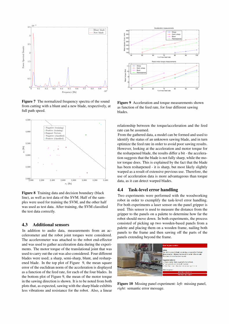
4.3 Additional sensorsIn addition to audio data, measurements from an ac-celerometer and the robot joint torques were considered.The accelerometer was attached to the robot end-effectorand was used to gather acceleration data during the experi-ments. The motor torque of the translational joint that wasused to carry out the cut was also considered. Four differentblades were used; a sharp, semi-sharp, blunt, and resharp-ened blade. In the top plot of Figure 9, the mean squareerror of the euclidean norm of the acceleration is displayedas a function of the feed rate, for each of the four blades. Inthe bottom plot of Figure 9, the mean of the motor torquein the sawing direction is shown. It is to be noted from bothplots that, as expected, sawing with the sharp blade exhibitsless vibrations and resistance for the robot. Also, a linear
40 50 60 70 80 90 100
100
150
200
250
300
350
400
% of max feed rate
Me
an
sq
ua
re o
f a
cc.
no
rm
Acceleration measurements
40 50 60 70 80 90 1007
8
9
10
11
% of max feed rate
Me
an
to
rqu
e (
Nm
)
Robot motor torque measurements
Sharp
Semi−sharp
Blunt
Resharpened
Sharp
Semi−sharp
Blunt
Resharpened
Figure 9 Acceleration and torque measurements shownas function of the feed rate, for four different sawingblades.
relationship between the torque/acceleration and the feedrate can be assumed.From the gathered data, a model can be formed and used toidentify the status of an unknown sawing blade, and in turnoptimize the feed rate in order to avoid poor sawing results.However, looking at the acceleration and motor torque forthe resharpened blade, the results differ a bit - the accelera-tion suggests that the blade is not fully sharp, while the mo-tor torque does. This is explained by the fact that the bladehas been resharpened - it is sharp, but most likely slightlywarped as a result of extensive previous use. Therefore, theuse of acceleration data is more advantageous than torquedata, as it can detect warped blades.
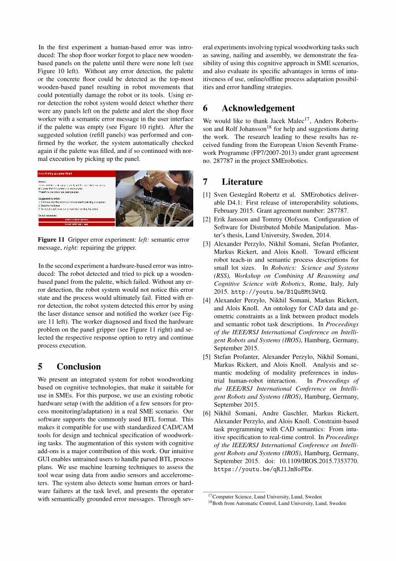
4.4 Task-level error handlingTwo experiments were performed with the woodworkingrobot in order to exemplify the task-level error handling.For both experiments a laser sensor on the panel gripper isused. This sensor is used to measure the distance from thegripper to the panels on a palette to determine how far therobot should move down. In both experiments, the processconsisted of picking up two wooden-based panels from apalette and placing them on a wooden frame, nailing bothpanels to the frame and then sawing off the parts of thepanels extending beyond the frame.
In the first experiment a human-based error was intro-duced: The shop floor worker forgot to place new wooden-based panels on the palette until there were none left (seeFigure 10 left). Without any error detection, the paletteor the concrete floor could be detected as the top-mostwooden-based panel resulting in robot movements thatcould potentially damage the robot or its tools. Using er-ror detection the robot system would detect whether therewere any panels left on the palette and alert the shop floorworker with a semantic error message in the user interfaceif the palette was empty (see Figure 10 right). After thesuggested solution (refill panels) was performed and con-firmed by the worker, the system automatically checkedagain if the palette was filled, and if so continued with nor-mal execution by picking up the panel.
In the second experiment a hardware-based error was intro-duced: The robot detected and tried to pick up a wooden-based panel from the palette, which failed. Without any er-ror detection, the robot system would not notice this errorstate and the process would ultimately fail. Fitted with er-ror detection, the robot system detected this error by usingthe laser distance sensor and notified the worker (see Fig-ure 11 left). The worker diagnosed and fixed the hardwareproblem on the panel gripper (see Figure 11 right) and se-lected the respective response option to retry and continueprocess execution.
5 ConclusionWe present an integrated system for robot woodworkingbased on cognitive technologies, that make it suitable foruse in SMEs. For this purpose, we use an existing robotichardware setup (with the addition of a few sensors for pro-cess monitoring/adaptation) in a real SME scenario. Oursoftware supports the commonly used BTL format. Thismakes it compatible for use with standardized CAD/CAMtools for design and technical specification of woodwork-ing tasks. The augmentation of this system with cognitiveadd-ons is a major contribution of this work. Our intuitiveGUI enables untrained users to handle parsed BTL processplans. We use machine learning techniques to assess thetool wear using data from audio sensors and accelerome-ters. The system also detects some human errors or hard-ware failures at the task level, and presents the operatorwith semantically grounded error messages. Through sev-
eral experiments involving typical woodworking tasks suchas sawing, nailing and assembly, we demonstrate the fea-sibility of using this cognitive approach in SME scenarios,and also evaluate its specific advantages in terms of intu-itiveness of use, online/offline process adaptation possibil-ities and error handling strategies.
6 AcknowledgementWe would like to thank Jacek Malec17, Anders Roberts-son and Rolf Johansson18 for help and suggestions duringthe work. The research leading to these results has re-ceived funding from the European Union Seventh Frame-work Programme (FP7/2007-2013) under grant agreementno. 287787 in the project SMErobotics.
7 Literature[1] Sven Gestegård Robertz et al. SMErobotics deliver-
able D4.1: First release of interoperability solutions,February 2015. Grant agreement number: 287787.
[2] Erik Jansson and Tommy Olofsson. Configuration ofSoftware for Distributed Mobile Manipulation. Mas-ter’s thesis, Lund University, Sweden, 2014.
[3] Alexander Perzylo, Nikhil Somani, Stefan Profanter,Markus Rickert, and Alois Knoll. Toward efficientrobot teach-in and semantic process descriptions forsmall lot sizes. In Robotics: Science and Systems(RSS), Workshop on Combining AI Reasoning andCognitive Science with Robotics, Rome, Italy, July2015. http://youtu.be/B1Qu8Mt3WtQ.
[4] Alexander Perzylo, Nikhil Somani, Markus Rickert,and Alois Knoll. An ontology for CAD data and ge-ometric constraints as a link between product modelsand semantic robot task descriptions. In Proceedingsof the IEEE/RSJ International Conference on Intelli-gent Robots and Systems (IROS), Hamburg, Germany,September 2015.
[5] Stefan Profanter, Alexander Perzylo, Nikhil Somani,Markus Rickert, and Alois Knoll. Analysis and se-mantic modeling of modality preferences in indus-trial human-robot interaction. In Proceedings ofthe IEEE/RSJ International Conference on Intelli-gent Robots and Systems (IROS), Hamburg, Germany,September 2015.
[6] Nikhil Somani, Andre Gaschler, Markus Rickert,Alexander Perzylo, and Alois Knoll. Constraint-basedtask programming with CAD semantics: From intu-itive specification to real-time control. In Proceedingsof the IEEE/RSJ International Conference on Intelli-gent Robots and Systems (IROS), Hamburg, Germany,September 2015. doi: 10.1109/IROS.2015.7353770.https://youtu.be/qRJ1JmNoFEw.
17Computer Science, Lund University, Lund, Sweden18Both from Automatic Control, Lund University, Lund, Sweden