On-Demand Virtual Highways for Dense UAS Operations David Sacharny 1 Thomas C. Henderson 2 Vista Marston 3 Abstract— The methods and protocols for coordinating airspace access can impact a number of metrics that are impor- tant to operators and system designers. For example, the time when an operator would like to fly a particular trajectory may be delayed if there are many intersecting trajectories by other aircraft. From a system-level perspective, it would be helpful to know how the number of simultaneous operations affects this measure of delay. Regarding the method of coordination, it is also important to consider what information must be shared in order to provide safe access - it may be undesirable to share detailed trajectory information. This paper describes a method for building on-demand airspace networks and applies Lane- Based Strategic Deconfliction (LBSD) to support dense airspace operations. I. INTRODUCTION AND BACKGROUND Currently, the most advanced method for coordinating dense airspace operations, under development in the first phase of NASA’s Advanced Air Mobility (AAM) National Campaign, is distributed cell-based deconfliction [1], [2]. Under this method, proposed by designers of Urban Air Mo- bility (UAM) and small unmanned aircraft systems (sUAS) traffic management systems (UTM), Providers of Services for UAM (PSU) and UAS Service Suppliers (USS) are re- sponsible for contacting other operators in the area, request- ing their trajectories and designing conflict free trajectories. There are benefits to this approach: the computation for deconfliction is distributed among the PSU and operators, and the resulting paths are optimal with respect to the individual vehicles. However there are also some downsides that make it untenable for certain operational requirements. For example, in order for a PSU or operator to design a conflict-free trajectory prior to launch (termed Strategic Deconfliction), it must know the precise trajectories of other aircraft within a cell (predefined divisions of the airspace). This has both security and privacy implications, as complete trajectory information can reveal the intent of operations. A completely tactical method, whereby vehicles did not strategically deconflict prior to launch, would resolve this issue at the expense of safety and the possibility of cascad- ing conflicts [3]. Another issue with this approach is that the information from contingencies, such as mechanical or communication failures, does not follow a uniform trajectory among the agents in the system. This again can result in cascading effects since decisions made by individuals across the system will inevitably be made with limited system 2 David Sacharny is with the School of Computing, University of Utah, Salt Lake City, UT, USA [email protected]1 Thomas C. Henderson is with the School of Computing, University of Utah, Salt Lake City, UT, USA [email protected]2 Vista Marston is with the School of Computing, University of Utah, Salt Lake City, UT, USA [email protected]observability (imagine all vehicles in an area having to re- plan simultaneously). The contributions of this paper include: 1) a method to create an airway structure that allows a computationally feasible deconfliction algorithm, 2) provides ways to obtain routes through this structure, 3) describes a user interface (GeoRq) which allows design and implementation of a UAS air traffic management system, including lanes and a reservation system, 4) provides results in a natural catastrophe scenario demonstrating the superior performance of the ap- proach compared to the FAA/NASA methodology. Structuring the airspace as virtual highways, coupled with the Lane-Based Approach to Strategic Deconfliction (LBSD) addresses the flaws in the cell-based FAA/NASA (Federal Aviation Administration/ National Aeronautics and Space Administration) approach [4], [5], [6], [7]. LBSD eliminates the need for operators and PSUs to obtain detailed trajectory information from other operations in the area. Additionally, the lane system directs the flow of contingency information along their paths, and agents within the system can have a reasonable expectation of the decisions that other agents will make due to the enhanced system observability. On the other hand, the lane-based approach restricts the possible trajectories that are allowed in a given airspace, and a coor- dinated reservation database must be established (distributed coordination platforms such as Apache Zookeeper are still applicable). We describe here methods for creating virtual highways over a given area on-demand, and a simulated operational scenario. The scenario envisions an earthquake disaster response in Salt Lake City, UT, a real prospect for the geologically active area. The goal of the designed system is to deliver water and food from designated depots to all nodes in an area. Figure 1 shows a sample of trajectories over a selected portion of the disaster area, over the University of Utah. The rest of the paper presents approaches to lane-based UAS traffic management, lane definition and construction, system design workflow, alternate route calculations, and finally, experimental results (simulations). II. LANE CONSTRUCTION Lanes compose a virtual highway network and are con- structed with specific rules to best make use of Lane-Based Strategic Deconfliction. The FAA/NASA strategic deconflic- tion requirements do not specify the algorithm for generating a conflict-free trajectory, however the algorithm is explicitly defined for LBSD to ensure computational guarantees and
Transcript
On-Demand Virtual Highways for Dense UAS Operations
David Sacharny1 Thomas C. Henderson2 Vista Marston3
Abstract— The methods and protocols for coordinatingairspace access can impact a number of metrics that are impor-tant to operators and system designers. For example, the timewhen an operator would like to fly a particular trajectory maybe delayed if there are many intersecting trajectories by otheraircraft. From a system-level perspective, it would be helpful toknow how the number of simultaneous operations affects thismeasure of delay. Regarding the method of coordination, it isalso important to consider what information must be shared inorder to provide safe access - it may be undesirable to sharedetailed trajectory information. This paper describes a methodfor building on-demand airspace networks and applies Lane-Based Strategic Deconfliction (LBSD) to support dense airspaceoperations.
I. INTRODUCTION AND BACKGROUNDCurrently, the most advanced method for coordinating
dense airspace operations, under development in the firstphase of NASA’s Advanced Air Mobility (AAM) NationalCampaign, is distributed cell-based deconfliction [1], [2].Under this method, proposed by designers of Urban Air Mo-bility (UAM) and small unmanned aircraft systems (sUAS)traffic management systems (UTM), Providers of Servicesfor UAM (PSU) and UAS Service Suppliers (USS) are re-sponsible for contacting other operators in the area, request-ing their trajectories and designing conflict free trajectories.There are benefits to this approach: the computation fordeconfliction is distributed among the PSU and operators,and the resulting paths are optimal with respect to theindividual vehicles. However there are also some downsidesthat make it untenable for certain operational requirements.For example, in order for a PSU or operator to designa conflict-free trajectory prior to launch (termed StrategicDeconfliction), it must know the precise trajectories of otheraircraft within a cell (predefined divisions of the airspace).This has both security and privacy implications, as completetrajectory information can reveal the intent of operations.A completely tactical method, whereby vehicles did notstrategically deconflict prior to launch, would resolve thisissue at the expense of safety and the possibility of cascad-ing conflicts [3]. Another issue with this approach is thatthe information from contingencies, such as mechanical orcommunication failures, does not follow a uniform trajectoryamong the agents in the system. This again can result incascading effects since decisions made by individuals acrossthe system will inevitably be made with limited system
2David Sacharny is with the School of Computing, University of Utah,Salt Lake City, UT, USA [email protected]
1Thomas C. Henderson is with the School of Computing, University ofUtah, Salt Lake City, UT, USA [email protected]
2Vista Marston is with the School of Computing, University of Utah,Salt Lake City, UT, USA [email protected]
observability (imagine all vehicles in an area having to re-plan simultaneously).
The contributions of this paper include:1) a method to create an airway structure that allows a
computationally feasible deconfliction algorithm,2) provides ways to obtain routes through this structure,3) describes a user interface (GeoRq) which allows design
and implementation of a UAS air traffic managementsystem, including lanes and a reservation system,
4) provides results in a natural catastrophe scenariodemonstrating the superior performance of the ap-proach compared to the FAA/NASA methodology.
Structuring the airspace as virtual highways, coupled withthe Lane-Based Approach to Strategic Deconfliction (LBSD)addresses the flaws in the cell-based FAA/NASA (FederalAviation Administration/ National Aeronautics and SpaceAdministration) approach [4], [5], [6], [7]. LBSD eliminatesthe need for operators and PSUs to obtain detailed trajectoryinformation from other operations in the area. Additionally,the lane system directs the flow of contingency informationalong their paths, and agents within the system can havea reasonable expectation of the decisions that other agentswill make due to the enhanced system observability. On theother hand, the lane-based approach restricts the possibletrajectories that are allowed in a given airspace, and a coor-dinated reservation database must be established (distributedcoordination platforms such as Apache Zookeeper are stillapplicable).
We describe here methods for creating virtual highwaysover a given area on-demand, and a simulated operationalscenario. The scenario envisions an earthquake disasterresponse in Salt Lake City, UT, a real prospect for thegeologically active area. The goal of the designed system isto deliver water and food from designated depots to all nodesin an area. Figure 1 shows a sample of trajectories over aselected portion of the disaster area, over the University ofUtah.
The rest of the paper presents approaches to lane-basedUAS traffic management, lane definition and construction,system design workflow, alternate route calculations, andfinally, experimental results (simulations).
II. LANE CONSTRUCTIONLanes compose a virtual highway network and are con-
structed with specific rules to best make use of Lane-BasedStrategic Deconfliction. The FAA/NASA strategic deconflic-tion requirements do not specify the algorithm for generatinga conflict-free trajectory, however the algorithm is explicitlydefined for LBSD to ensure computational guarantees and
Fig. 1. Selected UAS Paths in a Lane Network over Salt Lake City, UT.
enhanced system observability. To support on-demand lane-network creation, an algorithm was developed that takesan undirected two-dimensional graph and produces a three-dimensional system that is supported by LBSD (see Algo-rithm VERT2RA, which references Figure 2).
Algorithm VERT2RA (Vertex to Roundabout)On input:v0: a vertex on the groundemin: minumum lane lengthgup: upper roundabout elevationgdown: lower roundabout elevationG: undirected ground network
On output:r up: Upper Elevation Roundaboutr dn: Lower Elevation Roundabout
beginlet C be the circle of radius 1 centered at v0let N be the neighbors, vi, of v0 in GP ← {pi | pi = v0vi ∩ C}Add a point, pup, to P on C between existing pointsAdd a point, pdn, to P on C between existing pointsRup ← P with altitude rupRdn ← P with altitude rdnAdjust the radius of C so edges are longer than emin
(See Figure 2)Add directed edges to Rup between neighboring points
on C in counterclockwise directionAdd directed edges to Rdn between neighboring points
on C in counterclockwise directionAdd a directed edge from pup ∈ Rdn to pup ∈ Rup
Add a directed edge from pdn ∈ Rup to pdn ∈ Rdn
end
Roundabouts are augmented based on whether the de-signer requests land and/or launch lanes. Figure 3 showsan example four-way cross conflict replaced by an aerialroundabout with one launch lane (vertex 1) and three landlanes. Figure 4 shows an example of the same intersectionreplaced with a roundabout with land and launch lanes atevery vertex.
Once roundabouts are established, the process continues
to connect each with edges to form a fully connected(with respect to roundabout structures) airway network. Theroundabouts are connected via the following rules: if thevector between roundabout vertexes has heading between[0, π), then connect the lower structures (rdown in AlgorithmVERT2RA). If the vector has a heading between [π, 2π), thenconnect the upper structures (rup).
Fig. 2. Roundabout Formation Around Ground-Vertex v0
Fig. 3. Single Launch, Multiple Land Lane System
Fig. 4. Launch and Land Lanes for Every Ground Node
The lane network represents a set of reusable corridors(virtual highways), defined by waypoints, and radius (lanewidth). Whether the lanes are designed as extruded squaresor tubes depends on the packing requirements, but the spaceafforded for the range of vehicle trajectories is negligible.Figure 5 depicts a single roundabout and a possible trajectorythat was generated by imposing speed constraints on aninterpolation of waypoints (the lane end-points). Trajectorieswithin a lane system must be executed according to vehiclerequirements, and system designers must consider turning-rate limits before standardizing the speed and maximumdistance from the lane centerline. For the purpose of demon-strating the lane construction and execution of the LBSDalgorithm, agile vehicles are assumed.
III. DESIGN WORKFLOW
To demonstrate the scalability and design methodology,a subset of the road network in Salt Lake City, Utah, nearthe University of Utah, was taken from the complete roadnetwork dataset provided by the Automated GeographicReference Center (AGRC). This data was selected and storedin a GeoRq workspace (an integrated development environ-ment developed by the authors during the first phase ofNASA’s Advanced Air Mobility National Campaign). Theworkspace exposes several web application programming
Fig. 5. Smooth Piecewise, Clothoid Curve Simulating a Vehicle Path UsingLane Endpoints as Waypoints. The Lane System Supports a Wide Range ofPossible Trajectories, Imposing Constraints in terms of Maximum Distancefrom the Lane Center-line (Corridor Radius).
interfaces (API) that take the 2-dimensional road layer, buildan undirected graph from the raw linestrings, and queryelevation datasets to return a 3-dimensional graph for laneprocessing.
The prototype lane design and LBSD code runs in MAT-LAB, so a client program queries the workspace through theweb API, builds the lanes, and then runs the simulations.The resulting lane sets then are published through the webAPI so that the resulting airways can be accessed by otheragents. Figure 6 shows the representative dataset over theroads in Salt Lake City.
Fig. 6. Virtual Highway System GIS Layer in GeoRq Workspace
The GeoRq workspace is composed of a web map server,which exposes a standard Geographic Information Systems(GIS) web interface, a PostGIS database for storing geospa-tial data, and a web-based integrated development environ-ment (IDE) for viewing and manipulating data. Parameters,such as the lane radius and shape, can be prototyped onthis interface while design requirements are stored automat-ically in human/machine readable JSON files. While vehicleperformance capabilities still remain somewhat proprietary,
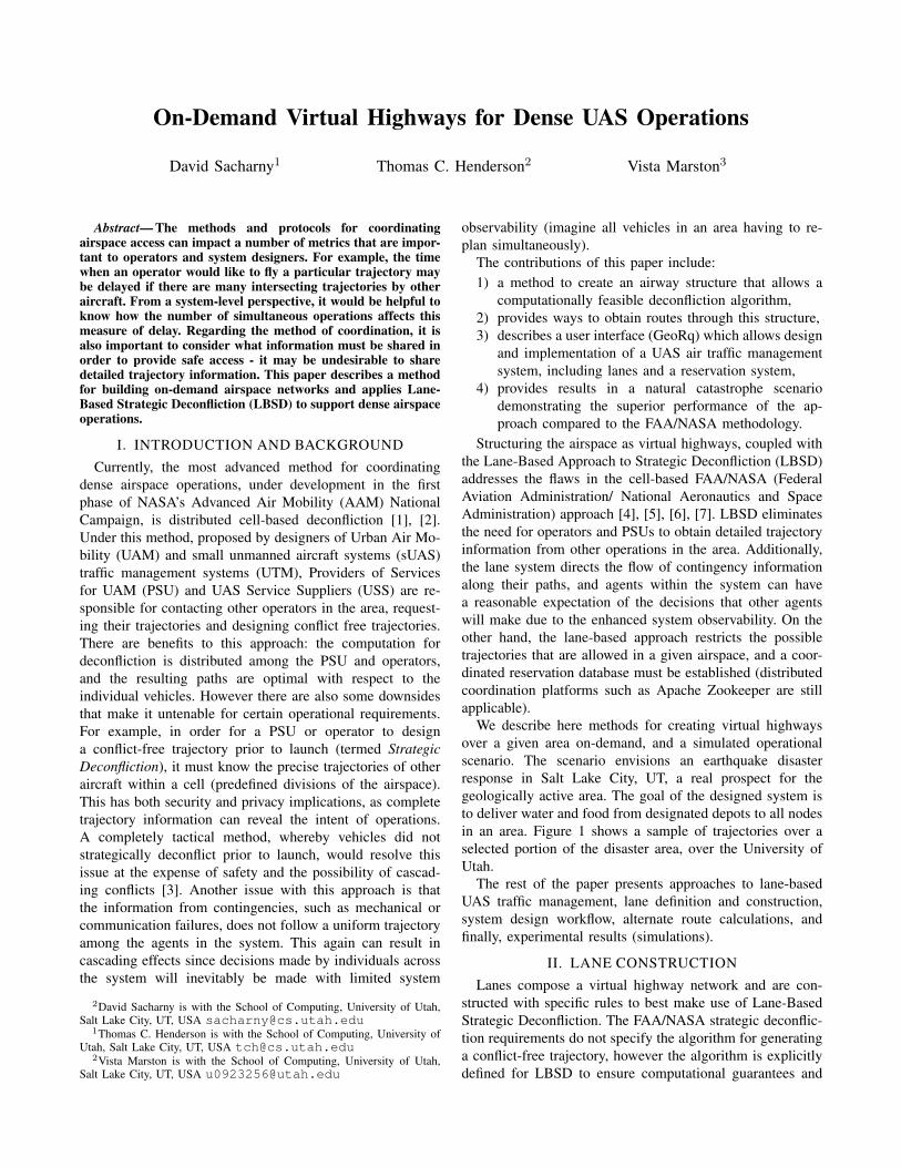
standards such as those for roads and roundabouts estab-lished by the United States Federal Highway Administra-tion (FHWA) should be expected for these networks. Forexample, the FHWA establishes standards for entry and exitspeed at roundabouts [8] based on their geometric properties(specifically, turning radius and lane width; see Figure 7).
Fig. 7. FHWA Recommendations for Max Speed in Ground Roundabouts[8].
IV. LANE-BASED UAS TRAFFIC MANAGEMENT
The UTM proposed here supports efficient and effective:• lane creation: the definition of a set of lanes (airways)
to allow flight from one ground location to another.• flight path determination: given launch and land ground
locations, return a sequence of lanes which goes fromthe launch location to the land location.
• flight reservations: given a lane sequence defined by aflight path, and a time interval of possible launch times,find the set of possible launch times that stay safelyseparated from any scheduled flights.
• contingency mitigation: lanes may be either pre-defined(e.g., emergency side lanes) or dynamically created(e.g., emergency landing lanes) in order to handle real-time departures from nominal flight paths.
In addition to the description of these, we provide a set ofMATLAB functions to deliver these capabilities; these can
be found at http://www.cs.utah.edu/∼tch/notes/UAM.
A. Lane Creation
Airways are defined by giving a set of ground locationsand edges between them. For example, this may be directlyobtained from GIS data by finding roads (the edge) and theirintersection points (the vertexes), or by manual specificationof the desired locations and their connectivity. In urbanenvironments, it may be desirable to locate the airways aboveroads. For example, the Utah Department of Transportation,Aeronautics Division, which is developing the UTM systemin Utah, wants airways above roadways since these are publicspaces, and a great deal of infrastructure is already in placeon the roadways to support UTM operations (existing accessto power and networking for new radar and GPS systems,etc.). Moreover, NASA supports this idea [9]:
With regard to the routes that UAM will tra-verse between two vertiports, a natural startingpoint for emergent UAM operations is to fly alongdefined helicopter routes ... These helicopter routestend to overlay highways and freeways on theground to mitigate social concerns.
However, the lane-based approach does not require thatairways be placed above roadways.
Thus, let V = {xi, yi} be the ground vertexes and E ={i, j} be the edges where i and j are indexes into V . Launchand land vertexes must be specified (as indexes into V ).Other required information includes the upper and loweraltitudes for airway lanes, as well as a minimum length lanefor roundabout structures. The airway constructed from thisdata defines the 3D vertexes created for the airway lanes, theairway lanes (as directed 3D line segments), and the indexesinto the launch and land lanes.
All airway lanes are one-way, and in order to allowtwo-way movement between ground vertexes requires twoseparate lanes which are separated vertically at some safedistance. Roundabouts are created at intersections to allowflights to choose outbound directions from a vertex. Thus,there are 3 types of basic lanes: (1) launch/land lanes, (2)roundabout lanes, and (3) between ground vertex lanes. Othertypes of lanes may be introduced for contingency handling.
V. ALTERNATE ROUTE CALCULATION
One of the issues with routing between launch and landsites is the possibility of congestion if all UAS follow thesame path to a destination. However, finding alternate pathsin the two-level airway network is complicated by the wish toavoid changing altitude multiple times. In order to overcomethis, we have developed a method to produce a set ofalternate lane sequences from a launch site to a land siteby exploiting the fact that an altitude change is necessitatedwhenever the heading of the UAS changes from directions[0, π) to [π, 2π) or vice versa. Thus, a search is carried outin the 2D ground network which minimizes the distance ofeach node from the line defined by the launch/land vertexes,as well as the number of changes of altitude. Figure 8 showsan example of alternate routes in the Salt Lake City ground
road network data. Once a path through the ground vertexesis found, then it is possible to find the corresponding paththrough the airway lanes (see Figure 9).
Fig. 8. Two Alternative Routes through the Ground Network whichMinimize Distance and Number of Altitude Changes.
Fig. 9. Airway Path Corresponding to Ground Path.
VI. EXPERIMENTS
The lane-based approach has been tested on a number ofscenarios. Figure 6 shows a set of airway lanes above part ofSalt Lake City which have been used to help determine UASAir Mobility structure and parameters for the Utah UTM.
Consider a Salt Lake City earthquake disaster scenarioin the East Bench area; about 25,000 people must receivea ration of 1 gallon of water (8 pounds) and 3 poundsof food each per day to be delivered by a set of UAS to477 distribution sites throughout the area; this makes a totalof 275,000 pounds per day. Assume each UAS has a loadcapacity of 100 pounds (note there are current models witha 200 pound capacity). Each delivery site will be servicedfrom a small set of depot sites where major supply reservesare housed. A performance comparison is made between theFAA and lane-based strategic deconfliction methods. Theparameters to be selected include: the number of depots (10or 50), the number of UAS (500 or 1000), the UAS speed (30
or 60 feet per second – about 20 and 40 mph, respectively),and the deconfliction method. Note that 6 deliveries arerequired for 500 UAS, whereas only 3 per day are nedeed for1,000 UAS. Performance measures include: average delay(time difference between actual and desired launch timesin seconds), maximum delay, average deconfliction time (inseconds), and maximum deconfliction time. In addition, threetypes of lane-based layouts are considered: lane networksplaced above actual roads (see Figure 10), a rectangular grid(see Figure 11), and a Delaunay triangulation of a set ofcomparable nodes over the area (see Figure 12). Results
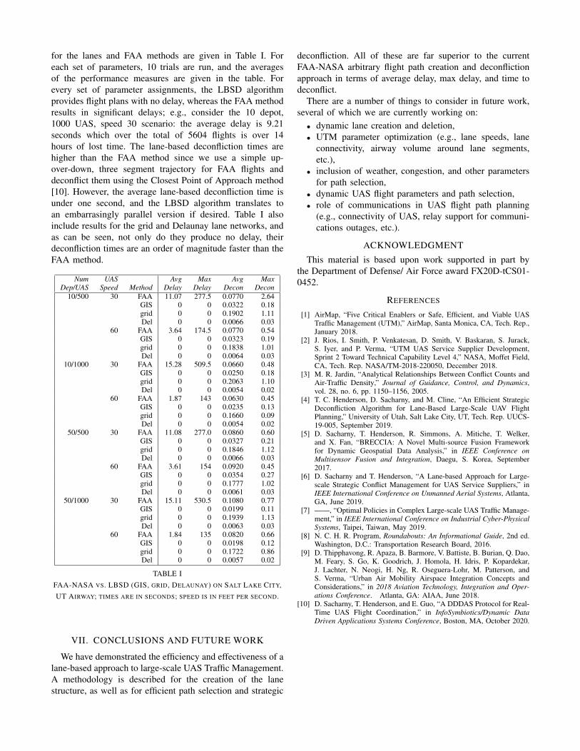
for the lanes and FAA methods are given in Table I. Foreach set of parameters, 10 trials are run, and the averagesof the performance measures are given in the table. Forevery set of parameter assignments, the LBSD algorithmprovides flight plans with no delay, whereas the FAA methodresults in significant delays; e.g., consider the 10 depot,1000 UAS, speed 30 scenario: the average delay is 9.21seconds which over the total of 5604 flights is over 14hours of lost time. The lane-based deconfliction times arehigher than the FAA method since we use a simple up-over-down, three segment trajectory for FAA flights anddeconflict them using the Closest Point of Approach method[10]. However, the average lane-based deconfliction time isunder one second, and the LBSD algorithm translates toan embarrasingly parallel version if desired. Table I alsoinclude results for the grid and Delaunay lane networks, andas can be seen, not only do they produce no delay, theirdeconfliction times are an order of magnitude faster than theFAA method.
Num UAS Avg Max Avg MaxDep/UAS Speed Method Delay Delay Decon Decon
TABLE IFAA-NASA VS. LBSD (GIS, GRID, DELAUNAY) ON SALT LAKE CITY,UT AIRWAY; TIMES ARE IN SECONDS; SPEED IS IN FEET PER SECOND.
VII. CONCLUSIONS AND FUTURE WORK
We have demonstrated the efficiency and effectiveness of alane-based approach to large-scale UAS Traffic Management.A methodology is described for the creation of the lanestructure, as well as for efficient path selection and strategic
deconfliction. All of these are far superior to the currentFAA-NASA arbitrary flight path creation and deconflictionapproach in terms of average delay, max delay, and time todeconflict.
There are a number of things to consider in future work,several of which we are currently working on:
• dynamic lane creation and deletion,• UTM parameter optimization (e.g., lane speeds, lane
connectivity, airway volume around lane segments,etc.),
• inclusion of weather, congestion, and other parametersfor path selection,
• dynamic UAS flight parameters and path selection,• role of communications in UAS flight path planning
(e.g., connectivity of UAS, relay support for communi-cations outages, etc.).
ACKNOWLEDGMENT
This material is based upon work supported in part bythe Department of Defense/ Air Force award FX20D-tCS01-0452.
REFERENCES
[1] AirMap, “Five Critical Enablers or Safe, Efficient, and Viable UASTraffic Management (UTM),” AirMap, Santa Monica, CA, Tech. Rep.,January 2018.
[2] J. Rios, I. Smith, P. Venkatesan, D. Smith, V. Baskaran, S. Jurack,S. Iyer, and P. Verma, “UTM UAS Service Supplier Development,Sprint 2 Toward Technical Capability Level 4,” NASA, Moffet Field,CA, Tech. Rep. NASA/TM-2018-220050, December 2018.
[3] M. R. Jardin, “Analytical Relationships Between Conflict Counts andAir-Traffic Density,” Journal of Guidance, Control, and Dynamics,vol. 28, no. 6, pp. 1150–1156, 2005.
[4] T. C. Henderson, D. Sacharny, and M. Cline, “An Efficient StrategicDeconfliction Algorithm for Lane-Based Large-Scale UAV FlightPlanning,” University of Utah, Salt Lake City, UT, Tech. Rep. UUCS-19-005, September 2019.
[5] D. Sacharny, T. Henderson, R. Simmons, A. Mitiche, T. Welker,and X. Fan, “BRECCIA: A Novel Multi-source Fusion Frameworkfor Dynamic Geospatial Data Analysis,” in IEEE Conference onMultisensor Fusion and Integration, Daegu, S. Korea, September2017.
[6] D. Sacharny and T. Henderson, “A Lane-based Approach for Large-scale Strategic Conflict Management for UAS Service Suppliers,” inIEEE International Conference on Unmanned Aerial Systems, Atlanta,GA, June 2019.
[7] ——, “Optimal Policies in Complex Large-scale UAS Traffic Manage-ment,” in IEEE International Conference on Industrial Cyber-PhysicalSystems, Taipei, Taiwan, May 2019.
[8] N. C. H. R. Program, Roundabouts: An Informational Guide, 2nd ed.Washington, D.C.: Transportation Research Board, 2016.
[9] D. Thipphavong, R. Apaza, B. Barmore, V. Battiste, B. Burian, Q. Dao,M. Feary, S. Go, K. Goodrich, J. Homola, H. Idris, P. Kopardekar,J. Lachter, N. Neogi, H. Ng, R. Oseguera-Lohr, M. Patterson, andS. Verma, “Urban Air Mobility Airspace Integration Concepts andConsiderations,” in 2018 Aviation Technology, Integration and Oper-ations Conference. Atlanta, GA: AIAA, June 2018.
[10] D. Sacharny, T. Henderson, and E. Guo, “A DDDAS Protocol for Real-Time UAS Flight Coordination,” in InfoSymbiotics/Dynamic DataDriven Applications Systems Conference, Boston, MA, October 2020.