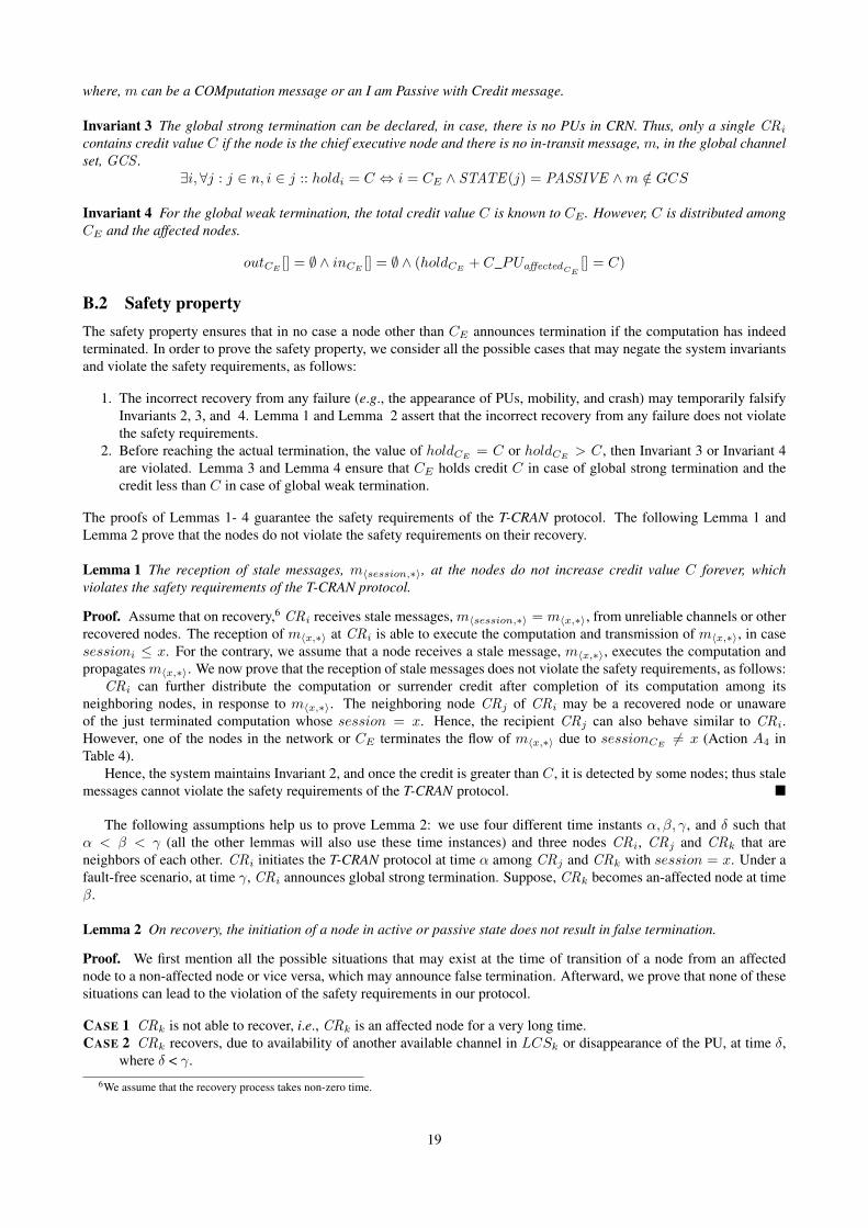
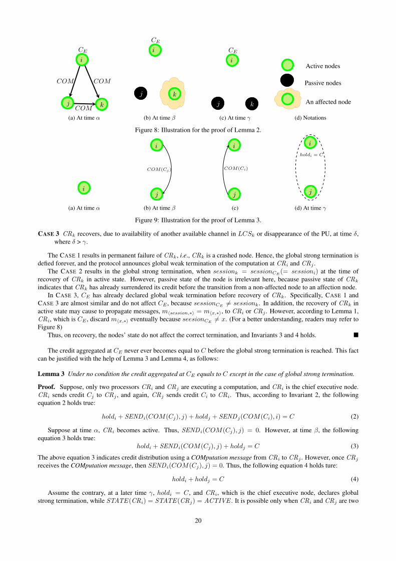
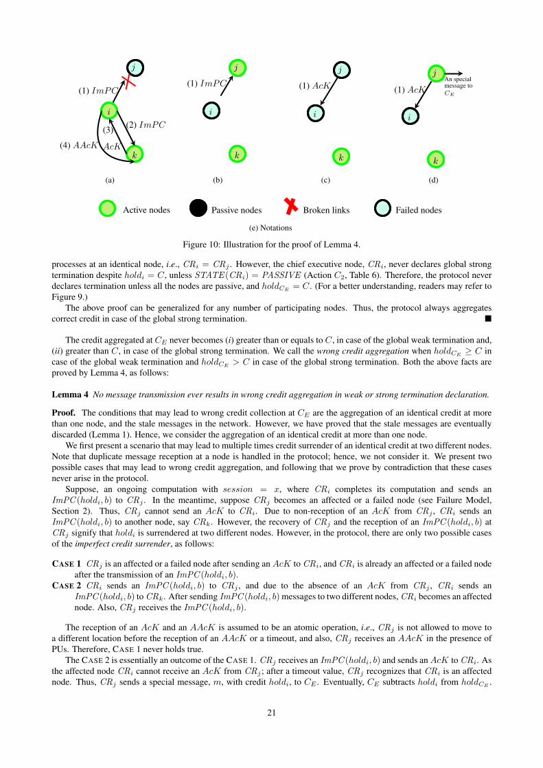
On Detecting Termination in Cognitive Radio Networks * † Shantanu Sharma 1 and Awadhesh Kumar Singh 2 1 Department of Computer Science, Ben-Gurion University of the Negev, Israel {[email protected]} ‡ 2 Department of Computer Engineering, National Institute of Technology, Kurukshetra, Haryana, India {[email protected]} Abstract The cognitive radio networks are an emerging wireless communication and computing paradigm. The cognitive radio nodes execute computations on multiple heterogeneous channels in the absence of licensed users (a.k.a. primary users) of those bands. Termination detection is a fundamental and non-trivial problem in distributed systems. In this paper, we propose a termination detection protocol for multi-hop cognitive radio networks where the cognitive radio nodes are allowed to tune to channels that are not currently occupied by primary users and to move to different locations during the protocol execution. The proposed protocol applies credit distribution and aggregation approach and maintains a new kind of logical structure, called the virtual tree-like structure. The virtual tree-like structure helps in decreasing the latency involved in announcing termination. Unlike conventional tree structures, the virtual tree-like structure does not require a specific node to act as the root node that has to stay involved in the computation until termination announcement; hence, the root node may become idle soon after finishing its computation. Also, the protocol is able to detect the presence of licensed users and announce strong or weak termination, whichever is possible. Keywords: Cognitive radio network, credit distribution and aggregation, heterogeneous channels, termination detection, virtual partitioning and merging, virtual tree-like structure. * Accepted in International Journal of Network Management (Wiley-IJNM). † A preliminary version of this paper has appeared in proceeding of the 17 th Pacific Rim International Symposium on Dependable Computing 2011 (PRDC) [35]. ‡ This work was carried out when Shantanu Sharma was a student in the Department of Computer Engineering, National Institute of Technology, Kurukshetra, Haryana, India.
Transcript
On Detecting Termination in Cognitive Radio Networks∗†
Shantanu Sharma1 and Awadhesh Kumar Singh2
1Department of Computer Science, Ben-Gurion University of the Negev, Israel {[email protected]} ‡
2Department of Computer Engineering, National Institute of Technology, Kurukshetra, Haryana, India{[email protected]}
Abstract
The cognitive radio networks are an emerging wireless communication and computing paradigm. The cognitive radionodes execute computations on multiple heterogeneous channels in the absence of licensed users (a.k.a. primary users)of those bands. Termination detection is a fundamental and non-trivial problem in distributed systems. In this paper,we propose a termination detection protocol for multi-hop cognitive radio networks where the cognitive radio nodes areallowed to tune to channels that are not currently occupied by primary users and to move to different locations during theprotocol execution. The proposed protocol applies credit distribution and aggregation approach and maintains a new kindof logical structure, called the virtual tree-like structure. The virtual tree-like structure helps in decreasing the latencyinvolved in announcing termination. Unlike conventional tree structures, the virtual tree-like structure does not require aspecific node to act as the root node that has to stay involved in the computation until termination announcement; hence,the root node may become idle soon after finishing its computation. Also, the protocol is able to detect the presence oflicensed users and announce strong or weak termination, whichever is possible.
Keywords: Cognitive radio network, credit distribution and aggregation, heterogeneous channels, termination detection,virtual partitioning and merging, virtual tree-like structure.
∗Accepted in International Journal of Network Management (Wiley-IJNM).†A preliminary version of this paper has appeared in proceeding of the 17th Pacific Rim International Symposium on Dependable Computing 2011
(PRDC) [35].‡This work was carried out when Shantanu Sharma was a student in the Department of Computer Engineering, National Institute of Technology,
Kurukshetra, Haryana, India.
1 IntroductionA vast growth of small and portable devices has culminated into the problem of bandwidth scarcity. Hence, it is becomingdifficult to provide seamless connectivity while executing various applications, e.g., email, web surfing, gaming, and videoconferencing (see Exhibit 10 in [14]). It is also noted that currently allocated spectrums have their significant portionsunderutilized [1]. The Cognitive Radio Networks (CRNs) [16] are a smart solution with a complex network structure toenhance the spectrum utilization.
The termination detection [11, 17] is a fundamental and non-trivial problem in distributed systems because theprocessors do not have the complete knowledge of all the other processors in the network, and there is no global clock inthe distributed computing environment. A solution to the termination detection problem informs termination of the taskbeing executed in the network.
1.1 Cognitive radio networksA cognitive radio network (see [4, 20, 8, 42, 5, 3, 41]) is a collection of heterogeneous cognitive radio nodes (orprocessors), called secondary users. The cognitive radio nodes (CRs) have sufficient computing power and power backupto operate on multiple heterogeneous channels (or frequency bands) in the absence of the licensed user(s), termed asprimary user(s), of the respective bands. The cognitive radio nodes have the LEIRA (learning, efficiency, intelligence,reliability, and adaptively) capability to scan and operate on different channels.
A channel that is not currently occupied by a primary user is called an available channel. Any two nodes that arein the transmission range of each other and tuned to a common available channel during an identical time interval, arecalled neighboring nodes. The appearance of a primary user (hereafter, the primary users will be known as PUs) on anavailable channel is a reason for CRs to switch the channel and to tune to another available channel, because the CRs arenot allowed to interrupt the primary users in any case.
The modern networking benchmark, CRN, presents many unique challenges in the field of communication as wellas computing, such as cognitive capability, reliability, and efficiency. Several challenges of CRNs are presented in [8].Interested readers may refer to [44, 29, 21, 28] for more details on cognitive radio networks.
In this paper, unless otherwise indicated, the words “cognitive radio node,” “cognitive radio,” “node,” and “processor”have the same meaning, and similarly, the words “cognitive radio network,” “network,” and “system” have been treatedas synonyms.
1.2 Termination detection (in cognitive radio networks)Nowadays, a large number of distributed applications –– e.g., mutual exclusion, leader election, checkpointing, globalstate detection [26] –– are executed on portable devices. In general, an application that executes on processors is knownas a normal computation or an underlying computation. A termination detection (TD) protocol [11, 17] is used toannounce termination of the normal computation. The termination declaration of a normal computation, when it hasindeed terminated — in a group of mobile devices that are geographically distributed and tuned on different channels— is an interesting challenge in cognitive radio networks. Hereafter, we use the word “computation” that refers to the“normal computation.”
A node may be in active or passive state during a computation. The nodes in the active state are called active nodes,and the nodes in the passive state are called passive nodes. The active nodes execute an assigned computation, and usually,after completion of the computation, they become passive. A passive node can become active on reception of a messagefrom an active node. Hence, it is clear that only active nodes can send messages; however, both the active and passivenodes can receive messages at any time.
Initially, all the nodes are passive in the network. Since only active nodes can send messages, we assume that thereexist a passive node that becomes active on reception of a message from outside world, and subsequently it initiates thecomputation. A computation is said to be terminated if and only if all the nodes are passive and there is no messagein-transit. A brief summary about TD protocols can be found in Chapter 7 of [26] and Chapter 9 of [18].
Any termination detection protocol can be initiated in two ways, as follows:
• Delayed initiation. The TD protocol is triggered by any node, i, that has been assigned a computation, and the samenode i is responsible for the announcement of termination; such an initiation is known as delayed initiation [33].Here, it is not mandatory that the node i was also the initiator of the computation; refer to Figure 1a, where node 1initiates the computation and node 3 initiates the termination detection protocol.
• Concurrent initiation. In the concurrent initiation, the TD protocol is overlaid on a computation and executesconcurrently. Here, the initiator of the computation is also responsible for the announcement of termination; referto Figure 1b, where the lower part represents the execution of the computation and the upper part represents the
1
Underlying computation
Termination detection protocol
Active nodes Overlaid nodes
Termination detection protocol initiator
1
2 5
3 4
1
(a) Delayed initiation.
1
2 5
3 4
1
2 5
3 4
1
(b) Concurrent initiation.
Figure 1: Two ways of termination detection protocol’s initiations.
execution of termination detection protocol that is being executed concurrently with the computation; and node 1 isthe initiator of both, the computation and the termination detection protocol.
Any termination detection protocol should satisfy the following properties:
• No false termination detection (safety). The termination of a computation is declared only when the computationhas indeed terminated (and only a single designated node can announce termination).
• Eventual termination detection (liveness). A single (designated) node announces termination within a finite amountof time.
The termination detection in CRN is more challenging as compared to the conventional wireless networks because ofthe following reasons:
• Network structure and communication links. The CRN is a network of time and space varying channels. Anytwo neighboring nodes, which must be tuned to an identical available channel, can communicate directly (usinga communication link). The appearance of a PU on a channel forces the neighboring CRs to vacate that channeland to tune to another identical available channel. However, finding another identical alternative available channel,for neighboring CRs, is not an easy task due to reasons like topological dynamics and varying capabilities of thenodes [6]. Hence, the communication link endurance during execution of any protocol is hard to guarantee.
• Reaction to a communication link break. In classical wireless networks, the nodes operate on a pre-decided channelthat provides them communication links. The communication links may break due to node mobility or nodefailure; hence, a new communication link detection takes place in a highly reactive manner without consideringparameters like endurance of the link. On the other hand, in CRN, the communication links may also break dueto the appearance of a PU leading to spectrum mobility that emphasizes on several factors before creating the newcommunication links [5].
• Sufficient resources. The computing nodes in wireless domain suffer from limited resources like bandwidth,memory, and battery power. Thus, several protocols focus on the reduction of the number of messages exchanged tominimize the need of bandwidth, memory, and battery power. However, CRNs have sufficient resources, especiallytemporarily unused spectrums (known as spectrum holes [5]) and computing power. Consequently, the focus ofresearch has been shifted to other challenges related to the execution of various applications.
• No definitive logical structure. Most of the computing protocol use quasi-stable logical structures, e.g., tree, ring,to leverage the design difficulties. The CRNs restrict a direct engagement of such logical structures due to time andspace varying channels.
In addition, unlike other ad hoc networks, the CRs show very loose synchronization, poor tolerance to the heterogeneityof mobile devices as well as channels, and an extra cost for searching a new channel (on the appearance of primary users).The presence of these challenges in cognitive radio networks make the design of computing and communication protocolsharder.
1.3 Our contribution and outline of the paperThe paper presents a concurrent initiation (see Figure 1b) based Termination detection protocol for Cognitive RAdioNetworks, called T-CRAN, henceforth. Moreover, our protocol can also be implemented in other dynamic networks, e.g.,cellular networks, mobile ad hoc networks (MANETs), vehicular ad hoc networks (VANETs). In this paper, we provide:
2
1. A credit distribution and aggregation based termination detection protocol for CRN, in Section 4, that declarestermination of computations despite the presence of PUs. Our protocol recognizes the cognitive radio nodes thatlose their single available channel due to the appearance of PUs and are unable to find other available channel.
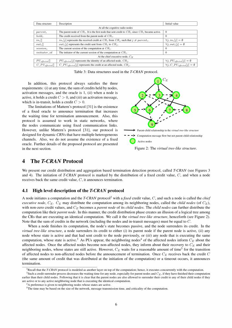
2. A new logical structure, called virtual tree-like structure (Figure 2), where the root node can be passive when itcompletes its computation, unlike conventional (logical) tree structures, where it is mandatory for the root node tostay in active state till the end of computation; in Section 4.
3. The T-CRAN protocol as guarded-actions, in Section 5. Section 6 explains the complete working of the proposedprotocol.
4. The analysis of message and time complexities of the proposed protocol, in Appendix A. The correctness proofs ofthe proposed protocol are given in Appendix B.
1.4 Related workThe termination detection (TD) protocol has been studied extensively in static distributed systems [11, 17, 9, 23, 31, 32,37, 19]. A detailed classification of TD protocols is given in [26, 30]. However, none of the existing TD protocols forstatic networks can be implemented straight forwardly in dynamic networks due to frequent topology changes in dynamicnetworks. Although, some TD protocols [39, 10, 27, 24, 25] exist for sensor networks and mobile ad hoc networks, theycan also not be implemented in CRNs due to unique challenges of cognitive radio networks, as mentioned in Section 1.2.
A novel algorithm for TD using credit distribution and aggregation was proposed by Mattern [31] and Huang [22, 23].A similar TD protocol for faulty distributed systems was proposed by Tseng [38]. However, these protocols failed towork in dynamic networks. A TD protocol for mobile cellular networks [39] based on credit distribution and aggregationis proposed that assumes the existence of the mobile switching center (MSS), which provides a centralize support to themobile nodes.
Johnson and Mittal [24] have tried to reduce the waiting time for termination declaration in dynamic networks.However, they consider the existence of an initiator node until termination declaration. The protocols proposed fordynamic networks [39, 27, 24, 25] have three major limitations: (i) they assume the existence of an initiator node untiltermination declaration; however, the mandatory existence of the initiator node increases the waiting time for the nodethat has completed its computation earlier than other nodes in the network. Also, the existence of an initiator node untiltermination declaration is not easy to guarantee in CRNs, (ii) they work on a single pre-decided channel, whereas, inCRN, computations and nodes work on multi-channels, and (iii) they consider only node mobility; they do not considerthe presence of some special users (like primary users) that also prevent the nodes to work.
In CRN, Mittal et al. [46] presents a neighbor discovery protocol with TD; however, they consider only terminationof the particular neighbor discovery scheme. The lightweight termination detection of Mittal et al. [46] is not related toour termination detection scheme. Note that in [46], the term “lightweight” has been used to highlight the fact that thenumber of control messages used in their protocol is minimal.
2 The System SettingsThis section outlines the preliminary assumptions about the environment, various types of messages (Table 2), and datastructures (Table 3). All the notations used in our protocol are given in Table 1.
Cognitive radio nodes. We consider a cognitive radio network of N cognitive radio nodes (CR1,CR2, . . . ,CRN ),where each node has a unique identity. However, a group of n CRs executes a single computation, where n ≤ N ,in finite time. The nodes are heterogeneous in terms of their computing capabilities, and they are allowed to moveduring protocol execution.
Each CR is aware of global channel set, local channel set, to be defined soon, and also the total number of nodes,N , in the network. Each node has a scan transceiver (a transceiver is a transmitter-receiver pair) that is responsiblefor scanning multiple heterogeneous channels. Such a scanning is beneficial for fast channel switching. However,a transceiver cannot transmit and receive simultaneously.
Communication channels. We divide communication channels into two sets: (i) global channel set (GCS ): a set of allthe, g, channels in the network, where g = |GCS|; (ii) local channel set (LCS ): a set of, l, available channels1 at anode, CRi, where li = |LCSi| and li ≤ g. However, the appearance of PU(s) on all g channels results in the valueof the local channel set to be zero, at each node. On the appearance of a PU, a CR is assumed to tune to anotheravailable channel, from its LCS , without interrupting the ongoing computation [5], similar to the handoff in mobilecellular networks.
1Recall that a channel that is not currently occupied by a primary user is known as an available channel.
3
CRN Cognitive radio network N The total number of cognitive radio nodes
CG Communication graph IG Interaction graph
V A set of cognitive radio nodes E A set of edges between neighboring nodes
v A set of cognitive radio nodes in an interaction graph e A set of edges in an interaction graph
CE Chief executive node (or initiator of the protocol) n Number of nodes involved in an identical computation
LCS Local channel set GCS Global channel set
l Number of available channels at a node g Number of the channels in GCS
Table 1: Notations.
A node, CRi, that does not possess any available channel in its LCSi (i.e., li = 0) due to the appearance ofPU(s), is called an affected node. An affected node is unable to send and receive messages. On the other hand,a node, CRj , that has at least one available channel in its LCSj (i.e., lj ≥ 1) is called a non-affected node.The communication channels are non-FIFO (first-in-first-out) and unreliable. However, the sent messages must bereceived at the receiver nodes without omissions, duplications, and in the same order as they were sent [12], if thereceiver is not an affected or a failed node (see failure model for details).
Network structure. We consider an asynchronous multi-hop cognitive radio network of N independent nodes. Werepresent the network by a communication graph, CG = [V, E , LCS]. In the communication graph, CG, Vrepresents a set of vertices (or processors in the network), E represents a set of edges where an edge betweena pair of neighboring nodes shows a bidirectional, direct, and non-FIFO wireless communication link, and LCSrepresents the local channel set of each CR.
Further, we define an interaction graph of size n ≤ N as: IG = [v, e]. In the interaction graph, IG, v ⊆V represents a set of CRs that are currently executing an identical computation and e ⊆ E represents a set ofedges where each edge connects any two neighboring nodes, CRi,CRj ∈ v, if they are executing an identicalcomputation. Note that we assume different interaction graphs for different computations.
Failure model. We assume that a cognitive radio node may fail in three different ways, as follows:
1. Due to the appearance of a PU and the node has only a single channel in its LCS , then the node is unable tosend and receive messages, and such a node is called an affected node.
2. Due to the swift movement of the node that may result in frequent topology change and transientnon-interaction of the highly mobile node with other nodes in the network. We call such nodes the failednodes.
3. Crash, i.e., when a node does not possess enough resources, like battery and computing power, it results inpermanent failure of the node, and such a node is called a crashed node. When a crashed node recovers byusers’ intervention, it does not possess the knowledge of updated data structures.
In this protocol, we focus on the impact of PUs on the nodes, and after that the recovery of such nodes whenPUs disappear. We do not consider any specific approach for recovery of failed nodes. The approach that worksin MANET to handle failed nodes is also applicable in CRN. In other words, we consider the failure-recoverymodel [2]. Whenever a node recovers, its state may be active or passive. It is possible that the failures occurfrequently and, thereafter, the nodes recover soon. Such frequent failures and recoveries are not useful for anypractical application; hence, we do not focus on these issues in our protocol. In addition, we assume that theaffected and crashed nodes are detected by at least one of the nodes, whose state is active. We also assume that thenodes do not exhibit Byzantine behavior.
Storage media. The termination cannot be detected as the decision variable itself can be corrupted by transient failuresleading to a false detection; hence, we store all the data structures in the non-volatile storage (i.e., stable storage).However, a consistent copy of the data is always available in the volatile memory. In the beginning, all the datastructures are initialized.
Furthermore, we assume that the cognitive radio nodes have sufficient battery and computing power, and anappropriate routing protocol is in place for message delivery. For ease of presentation and understanding, we considera single instance of a single computation (i.e., a single interaction graph, IG) in the network; however, the proposedprotocol is able to handle multiple instances of multiple computations. We do not specify any neighbor discovery protocol;however, we assume that each CR knows its neighboring nodes using some existing neighbor discovery protocols,e.g., [34].
Types of messages. In our protocol, we use various messages (message details are given in Table 2, and a simplifiedillustration of messages transmission is shown in Figures 3 and 4) that are classified into control messages and non-controlmessages. The control messages have the highest transmission priority, and they are forwarded by (intermediate) passive
4
Control messages
COMputation message COM (C) send by CRi to its active/passive neighboring nodes to distribute the computation.
I am Passive with Creditmessage
ImPC (C, b) send by CRi to all the active nodes that had sent credits to CRi previously including the parent nodeof CRi. An ImPC (C, b) message contains credit information, C, and the total number of activechild nodes, b, of the sender CRi. The value of b is set to 0 if the ImPC is sent to nodes other thanthe parent nodes.
I am Passive message ImP(p) send by CRi to all its child nodes piggybacked with a new parent’s, CRp, information.
AcKnowledgement message AcK send by CRj to CRi in order to acknowledge credit receipt, if CRi has surrendered its credit toCRj .
Acknowledgement of AcK
messageAAcK send by CRi to CRj if CRi has received an AcK message from CRj . The highest priority
messages, i.e., AcK and AAcK, provide a three way handshake when CRi surrenders its credit toCRj . The reception of AcK and AAcK messages are assumed to be atomic (and the delivery timeof AcK and AAcK messages is very small, unlike other control messages).
Termination Message TM send by the chief executive node, CE , to all the nodes of the interaction graph to declare terminationof the computation.
Non-control messages
Primary user affected Nodesmessage
PaN send by CRi that is neighboring node of CRj to CE . This message holds the identity of the affectednode, CRj , and the credit that had sent to CRj by CRi or from CRi to CRj .
Nodes released by Primaryuser message
NaP send by CRi to CE and all its neighbors whose states are active. A NaP message holds the identityof CRi, that was an affected node earlier; however, now CRi is a non-affected node.
Remarks: (i) We use a notation SENDi(m, j) to show the message transmission of m from CRi to CRj .(ii) The message transmission is shown in Figures 3 and 4.
Table 2: Message types used in the T-CRAN protocol.
nodes too. It is worth noting that only control messages require communication cost, and non-control messages can bepiggybacked on the control or heartbeat messages.
All the control and non-control messages include a tuple 〈session, initiator_id〉, that (i) avoids the need of a logicalclock, which is hard to implement in CRN, (ii) distinguishes any two messages, (iii) distinguishes a message from stalemessages (a message that is received after the termination declaration, and so belongs to the terminated computation, isknown as a stale message, throughout the paper).
Types of data structures. In our protocol, the data structures are divided into two categories: (i) at all the cognitive radionodes, and (ii) at the chief executive node, CE , (a node that is responsible for the announcement of termination). Detailsof these data structures are given in Table 3.
3 BackgroundA large number of termination detection (TD) protocols have been introduced for fault-free and faulty distributedsystems. They are based on different scheme, e.g., snapshot, credit distribution and aggregation, logical tree, and ringstructures [30]. The snapshot based TD protocols require complex data structures to be maintained at each participatingnode because the amount of information exchanged is usually very high. Consequently, they have a large waiting time forthe announcement of termination that is unsuitable for ad hoc networks. On the other hand, the maintenance of logicalstructures (rings and trees) is a computation intensive task, and it requires frequent exchange of coordination messagesto handle dynamic topology in ad hoc environment. Such a high overhead is deterrent in the use of logical structures.Therefore, we consider the credit distribution and aggregation approach to design a TD protocol for CRN.
For the sake of completeness and understanding of credit distribution and aggregation based TD protocols, we presentthe first credit distribution and aggregation based TD protocol, given by Mattern [31]. This protocol assumes the existenceof an oracle that is responsible for initiation of the computation and termination detection.
Initially, the network has all the nodes in passive state, and the credit at each node is zero. In the beginning of acomputation, the oracle, which is supposed to have credit value 1, distributes the credit value among the nodes usingactivation messages. Thus, each activation message holds a credit value, 0 < C < 1. Now, the oracle waits to receivecredits back. Once, the cumulated credit has value one, the oracle announces termination. This protocol uses four rules,as follows:
R1 When a passive node receives an activation message with credit 0 < C < 1, the node becomes active, holds the creditC, and executes the assigned computation.
R2 When an active node receives an activation message with credit 0 < C < 1, the credit value, C, is transferred to theoracle.
R3 When an active node, having credit C, sends an activation message, the node sends only C2 credit with the message.
R4 When a node becomes passive, it surrenders its credit to the oracle.
5
Data structure Description Initial value
At all the cognitive radio nodes
parenti The parent node of CRi. It is the first node that sent credit to CRi since CRi became active. 0
holdi The credit received from the parent node of CRi. 0
ini[] ini[j] represents the received credit at CRi from CRj such that j 6= parenti. ∀j, ini[j] = ∅outi[] outi[j] represents the credit sent from CRi to CRj . ∀j, outi[j] = ∅sessioni The current session of the computation at CRi. 0
initiator_id The initiator of the current session of the computation at CRi. 0
At the chief executive node, CE
PUaffected [] PUaffected [j] represents the identity of an affected node, CRj . ∀j, PUaffected [j] = ∅C _PUaffected [] C_PUaffected [j] represents the credit at an affected node, CRj . ∀j, C_PUaffected [j] = ∅
Table 3: Data structures used in the T-CRAN protocol.
1
2 4
7
3
5 6 8
9
CE
Parent-child relationship in the virtual tree-like structure
Computation message flow but not parent-child relationship
Active nodes
1
Figure 2: The virtual tree-like structure.
In addition, this protocol always satisfies the threerequirements: (i) at any time, the sum of credits held by nodes,activation messages, and the oracle is 1, (ii) when a node isactive, it holds a credit C > 0, and (iii) an activation message,which is in-transit, holds a credit C > 0.
The limitations of Mattern’s protocol [31] is the existenceof a fixed oracle to announce termination that increasesthe waiting time for termination announcement. Also, thisprotocol is assumed to work in static networks, wherethe nodes communicate using fixed communication links.However, unlike Mattern’s protocol [31], our protocol isdesigned for dynamic CRNs that have multiple heterogeneouschannels. Also, we do not assume the existence of a fixedoracle. Further details of the proposed protocol are presentedin the next section.
4 The T-CRAN ProtocolWe present our credit distribution and aggregation based termination detection protocol, called T-CRAN (see Figures 3and 4). The initiation of T-CRAN protocol is marked by the distribution of a fixed credit value, C, and when a nodereceives back the same credit value, C, it announces termination.
4.1 High level description of the T-CRAN protocolA node initiates a computation and the T-CRAN protocol2 with a fixed credit value, C, and such a node is called the chiefexecutive node, CE . CE may distribute the computation among its neighboring nodes, called the child nodes (of CE),with non-zero credit values, and CE becomes a parent node of its child nodes. The child nodes can further distribute thecomputation like their parent node. In this manner, the credit distribution phase creates an illusion of a logical tree amongthe CRs that are executing an identical computation. We call it the virtual tree-like structure, henceforth (see Figure 2).Note that the sum of credits in the network (including the nodes and in-transit messages) must be equal to C.
When a node finishes its computation, the node’s state becomes passive, and the node surrenders its credit. In thevirtual tree-like structure, a node surrenders its credit to either (i) its parent node if the parent node is active, (ii) anynode whose state is active and that had sent credit to the node previously, or (iii) any node that is executing the samecomputation, whose state is active.3 As PUs appear, the neighboring nodes4 of the affected nodes inform CE about theaffected nodes. Once the affected nodes become non-affected nodes, they inform about their recovery to CE and theirneighboring nodes, whose states are still active. However, CE waits for a reasonable amount of time5 for the transitionof affected nodes to non-affected nodes before the announcement of termination. Once CE receives back the credit C(the same amount of credit that was distributed at the initiation of the computation) or a timeout occurs, it announcestermination.
2Recall that the T-CRAN protocol is modeled as another layer on top of the computation; hence, it executes concurrently with the computation.3Such a credit surrender process decreases the waiting time for any node, especially for parent nodes and CE , if they have finished their computation
earlier than their child nodes. Following that it is clear that the parent nodes are also allowed to surrender their credit to any of their child nodes if theyare active or to any active neighboring node that is executing the identical computation.
4A preference is given to neighboring nodes whose states are active.5The time may be based on the size of the network, message transmission time, and criticality of the computation.
6
parenti = i
holdi = 50
ini[] = ∅outi[j] = 50
COM (50)
CRi
parentj = i
holdj = 26
inj [] = ∅outj [k] = 24
CRj
COM (24)parentk = j
holdk = 24
ink[] = ∅outk[] = ∅
CRk
1
(a)
parenti = i
holdi = 50
ini[k] = 12
outi[j] = 50
CRi
parentj = i
holdj = 26
inj [] = ∅outj [k] = 24
CRj
parentk = j
holdk = 12
ink[] = ∅outk[i] = 12
CRk
COM (12)
1
(b)
parenti = i
holdi = 62
ini[] = ∅outi[j] = 50
CRi
parentj = i
holdj = 38
inj [] = ∅outj [] = 0
CRj
parentk = 0
holdk = 0
ink[] = ∅outk[] = ∅
CRk
ImP(j)
ImPC(12, 1)
AcK
AAcK
1
(c)
parenti = 0
holdi = 0
ini[] = ∅outi[] = ∅
CRi
parentj = j
holdj = 100
inj [] = ∅outj [] = ∅
CRj
parentk = 0
holdk = 0
ink[] = ∅outk[] = ∅
CRkImPC(62, 0)
AcK
AAcK
1
(d)
parenti = 0
holdi = 0
ini[] = ∅outi[] = ∅
CRi
parentj = 0
holdj = 0
inj [] = ∅outj [] = ∅
CRj
parentk = 0
holdk = 0
ink[] = ∅outk[] = ∅
CRk
TM TM
1
(e)
The chief executive node
Passive nodes
Active nodes
1
(f)
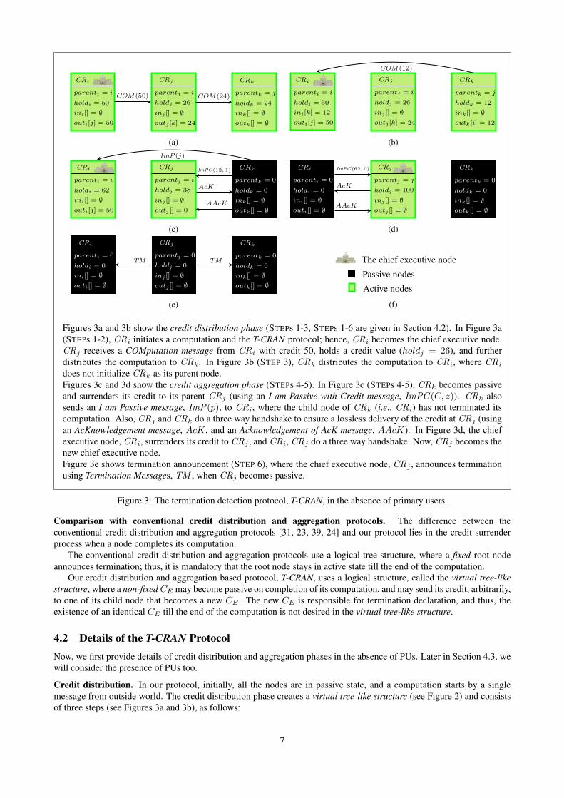
Figures 3a and 3b show the credit distribution phase (STEPs 1-3, STEPs 1-6 are given in Section 4.2). In Figure 3a(STEPs 1-2), CRi initiates a computation and the T-CRAN protocol; hence, CRi becomes the chief executive node.CRj receives a COMputation message from CRi with credit 50, holds a credit value (holdj = 26), and furtherdistributes the computation to CRk. In Figure 3b (STEP 3), CRk distributes the computation to CRi, where CRi
does not initialize CRk as its parent node.Figures 3c and 3d show the credit aggregation phase (STEPs 4-5). In Figure 3c (STEPs 4-5), CRk becomes passiveand surrenders its credit to its parent CRj (using an I am Passive with Credit message, ImPC (C, z)). CRk alsosends an I am Passive message, ImP(p), to CRi, where the child node of CRk (i.e., CRi) has not terminated itscomputation. Also, CRj and CRk do a three way handshake to ensure a lossless delivery of the credit at CRj (usingan AcKnowledgement message, AcK, and an Acknowledgement of AcK message, AAcK). In Figure 3d, the chiefexecutive node, CRi, surrenders its credit to CRj , and CRi, CRj do a three way handshake. Now, CRj becomes thenew chief executive node.Figure 3e shows termination announcement (STEP 6), where the chief executive node, CRj , announces terminationusing Termination Messages, TM , when CRj becomes passive.
Figure 3: The termination detection protocol, T-CRAN, in the absence of primary users.
Comparison with conventional credit distribution and aggregation protocols. The difference between theconventional credit distribution and aggregation protocols [31, 23, 39, 24] and our protocol lies in the credit surrenderprocess when a node completes its computation.
The conventional credit distribution and aggregation protocols use a logical tree structure, where a fixed root nodeannounces termination; thus, it is mandatory that the root node stays in active state till the end of the computation.
Our credit distribution and aggregation based protocol, T-CRAN, uses a logical structure, called the virtual tree-likestructure, where a non-fixed CE may become passive on completion of its computation, and may send its credit, arbitrarily,to one of its child node that becomes a new CE . The new CE is responsible for termination declaration, and thus, theexistence of an identical CE till the end of the computation is not desired in the virtual tree-like structure.
4.2 Details of the T-CRAN ProtocolNow, we first provide details of credit distribution and aggregation phases in the absence of PUs. Later in Section 4.3, wewill consider the presence of PUs too.
Credit distribution. In our protocol, initially, all the nodes are in passive state, and a computation starts by a singlemessage from outside world. The credit distribution phase creates a virtual tree-like structure (see Figure 2) and consistsof three steps (see Figures 3a and 3b), as follows:
7
parenti = i
holdi = 50
ini[] = ∅outi[j] = 50
PUaffectedi[] = ∅
C_PUaffectedi[] = ∅
COM(50)
CRi
parentj = i
holdj = 25
inj [] = ∅outj [] = 25
CRj
COM(25)parentk = j
holdk = 25
ink = ∅outk[] = ∅
CRk
1
(a)
PaN(k, 25) parentj = i
holdj = 25
inj [] = ∅outj [] = ∅
CRj
parentk = j
holdk = 25
ink = ∅outk[] = ∅
CRkparenti = i
holdi = 50
ini[] = ∅outi[j] = 50
PUaffectedi[] = k
C_PUaffectedi[] = 25
CRi
1
(b)
NaP (k)parentj = i
holdj = 25
inj [] = ∅outj [] = 25
CRj
parentk = j
holdk = 25
ink = ∅outk[] = ∅
CRk
NaP (k)
parenti = i
holdi = 50
ini[] = ∅outi[j] = 50
PUaffectedi[] = ∅
C_PUaffectedi[] = ∅
CRi
1
(c)
The chief executive node
Affected nodesActive nodes
1
(d)
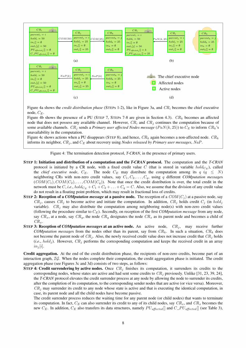
Figure 4a shows the credit distribution phase (STEPs 1-2), like in Figure 3a, and CRi becomes the chief executivenode, CE .Figure 4b shows the presence of a PU (STEP 7, STEPs 7-8 are given in Section 4.3). CRk becomes an affectednode that does not possess any available channel. However, CRi and CRj continues the computation because ofsome available channels. CRj sends a Primary user affected Nodes message (PaN(k, 25)) to CE to inform CRk’sunavailability in the computation.Figure 4c shows actions when a PU disappears (STEP 8), and hence, CRk again becomes a non-affected node. CRk
informs its neighbor, CRj , and CE about recovery using Nodes released by Primary user messages, NaP .
Figure 4: The termination detection protocol, T-CRAN, in the presence of primary users.
STEP 1: Initiation and distribution of a computation and the T-CRAN protocol. The computation and the T-CRANprotocol is initiated by a CR node, with a fixed credit value C (that is stored in variable holdCE
), calledthe chief executive node, CE . The node CE may distribute the computation among its q (q ≤ N )neighboring CRs with non-zero credit values, say C1, C2, . . . , Cq , using q different COMputation messages(COM (C1), COM(C2), . . . , COM(Cq)). Note that once the credit distribution is over, the total credit in thenetwork must be C, i.e., holdCE
+C1 +C2 + . . .+Cq = C. Also, we assume that the division of any credit valuedo not result in a floating point problem, which may result in fractional loss of credits.
STEP 2: Reception of a COMputation message at a passive node. The reception of a COM (Cj) at a passive node, sayCRj , causes CRj to become active and initiate the computation. In addition, CRj holds credit Cj (in holdjvariable). CRj may also distribute the computation among neighboring node(s) with non-zero credit values(following the procedure similar to CE). Secondly, on reception of the first COMputation message from any node,say CRx, at a node, say CRy , the node CRy designates the node CRx as its parent node and becomes a child ofCRx.
STEP 3: Reception of COMputation messages at an active node. An active node, CRj , may receive furtherCOMputation messages from the nodes other than its parent, say from CRk. In such a situation, CRk doesnot become the parent node of CRj . Also, the newly received credit value does not increase credit that CRj holds(i.e., holdj). However, CRj performs the corresponding computation and keeps the received credit in an arrayinj [i].
Credit aggregation. At the end of the credit distribution phase, the recipients of non-zero credits, become part of aninteraction graph, IG. When the nodes complete their computation, the credit aggregation phase is initiated. The creditaggregation phase (see Figures 3c and 3d) consists of two steps, as follows:STEP 4: Credit surrendering by active nodes. Once CRj finishes its computation, it surrenders its credits to the
corresponding nodes, whose states are active and had sent some credits to CRj previously. Unlike [31, 23, 39, 24],the T-CRAN protocol elevates the credit surrender process at any node by allowing the node to surrender its credits,after the completion of its computation, to the corresponding sender nodes that are active (or vice versa). Moreover,CRj may surrender its credit to any node whose state is active and that is executing the identical computation, incase, its parent node and all the child nodes have become passive.The credit surrender process reduces the waiting time for any parent node (or child nodes) that wants to terminateits computation. In fact, CE can also surrender its credit to any of its child nodes, say CRx, and CRx becomes thenew CE . In addition, CE also transfers its data structures, namely PUaffected [] and C_PUaffected [] (see Table 3),
8
A primary user
CRs
The chief executive node, CE
Primary user affected CRN (CRNP )Non-primary user affected CRN (CRNN )
Broken link due to a primary user
1
Figure 5: The abstract view of a primary user’s appearance in cognitive radio networks.
to CRx at the time of credit surrender.STEP 5: Three-way handshake. In the absence of failures, CRi acknowledges CRj (to inform CRj that CRi has
received the credit back from CRj) using an AcKnowledgement message (AcK). CRj also acknowledges thereception of the AcK to CRi using an Acknowledgement of AcK message (AAcK). Such a mechanism provides athree-way handshake and ensures safe delivery of credits. However, the non-reception of an AcK at CRj , after atimeout, causes CRj to surrender its credit to another node whose state is active. The three-way handshake can beavoided, if there is a guarantee of message delivery at the receiving node, which is neither an affected node nor acrashed node (using an algorithm suggested in [12]).
Termination declaration. In the beginning, any node may initiate the termination detection protocol and becomes CE .However, once initiated, any node may take charge as CE (according to STEP 4), and the new CE declares the finaltermination (see Figure 3e). In fact, between initiation and termination of any computation, there could be multiple chiefexecutive charge handovers in the network.STEP 6: Termination announcement. When CE holds credit C and it has completed its computation, CE informs all
the other nodes in the interaction graph, IG, about the termination of the computation using Termination Messages(TM ). However, in any case, only a single node (i.e., CE) can announce termination (when it holds credit C). Wealso relax the termination detection criteria in Section 4.4.
4.3 Detection of primary user(s)The appearance of a PU perturbs the working of the CRs (as well as the termination detection protocol) and forces themto tune to another available channel in their LCS . Specifically, the appearance of a PU can be visualized similar to thenetwork partitioning, as it partitions the network into two parts, as explained below:
• Primary user(s) affected CRN (CRNP ): It is a part of the network that consists of affected nodes, which cannotsend or receive any message.
• Non-primary user(s) affected CRN (CRNN ): It consists of all the CRs that have completed their computation andsurrendered their credit to the respective senders (of the credit).
In Figure 5, we show these two CRNs, namely CRNP and CRNN , where, the total credit C is the sum of credits atCRNP and credit at CRNN . Further, CE waits for credits of affected nodes. Intuitively, the appearance of a PU can beinterpreted as follows:
• When a PU never ever leaves the channel and the nodes are unable to tune to another available channel, the state ofthe affected nodes can be interpreted as a crash (that is a permanent failure).
• When a PU persists in the network for a very long time, the computation at the affected nodes can be interpreted asexcessively slowed down due to PUs.
However, both the above situations are indistinguishable for other nodes in the network. Thus, we develop an approachthat is useful to declare termination even in the presence of primary users. Note that the available hardware approaches—- match filter, energy filter, feature filter, inference temperature management [7] and spectrum sensing techniques [40,45, 43] –– are capable enough to detect the presence of PUs (by any CR). Specifically, the appearance of a PU may turn anon-affected node to an affected node (see STEP 7 and Figure 4b), and when the PU leaves the channel, an affected nodebecomes a non-affected node (see STEP 8 and Figure 4c), as follows:
STEP 7: Node failure due to the appearance of PUs. An affected node, say CRj , is detected by all the neighboringnodes, whose states are active (and these neighboring nodes may be the parent node or child nodes of CRj). All theneighboring nodes of CRj , whose states are active, inform CE about such a situation using a Primary user affectedNodes message (PaN ). Each PaN holds the identity of CRj , and the credit sent (received) to (from) CRj . Onreception of each PaN , CE enlists CRj and CRj’s credit in the corresponding data structures (namely, PUaffected []and C_PUaffected []).
9
Further, all the senders of PaN messages remove credit information about CRj from their in[] or out[], whicheverthe case may be. Note that, like any CR, CE can also detect its affected neighboring nodes, and it does the sameas on receiving a PaN and removes them from inCE
[] or outCE[]. However, other PaN messages, about the same
affected nodes require the identical processing at CE .Moreover, the reception of PaN messages is sufficient to declare termination of the computation, after a reasonableamount of time, in case the following equation 1 holds true:
outCE[] = ∅ ∧ inCE
[] = ∅ ∧ (holdCE+ C_PUaffectedCE
[] = C) (1)
Such a termination detection is called weak termination (see Section 4.4 for details, and the equation 1 will beproved in Section B.2).
STEP 8: Recovery of the affected nodes. Once an affected node, say CRj , becomes a non-affected node, CRj informsCE and all its neighboring nodes, whose states are active, using Nodes released by Primary user messages (NaP ).On reception of a NaP message at CE , CE first checks whether the computation has terminated. If not, then CE
informs CRj about the ongoing computation (with CRj’s credit value). On the other hand, if the neighboringnodes of CRj have not completed the computation, they hold the credit back in their respective data structures,in[] or out[], whichever the case may be. In this manner, the total credit remains identical as it was at the time ofcomputation initiation.
4.4 Termination declarationAny kind of node failure (e.g., non-availability of a channel in LCS , mobility of the nodes, and crash, given in FailureModel, Section 2) may lead to either temporary or permanent disconnection of the CRs from the network as well asdiscontinuity of the computation. However, the failures are quite common in CRN. It is not surprising that such adisconnection may leave CE to starve to collect the necessary credits for termination declaration. Hence, in order toavoid the endless waiting at CE , CE may declare either kind of termination, as defined below:
• Strong termination infers passive state of all the CRs that were executing an identical computation and the absenceof in-transit messages. It is also called correct and safe termination announcement.
• Weak termination refers to CRNP and CRNN , where the state of all the non-affected CRs is passive, and there isno in-transit message. Also, the disappearance of PUs (or recovery from mobility) results in the strong termination.The main advantage of weak termination is the detection of affected nodes and to avoid endless waiting to announcestrong termination. However, our approach announces weak termination if equation 1 holds true.The significance of weak termination can be figured out by the following example: suppose, we start a leaderelection (LE) protocol [36] in CRN that consists of 100 nodes, initially. During the execution of the LE protocol,say 20 nodes became affected nodes. Thus, it is impractical to wait for strong termination, because a leader mayalso be elected out of 80 nodes. After recovery from PUs, the remaining 20 nodes may join the network. Such ascenario reduces the waiting time for the announcement of a leader, maintains computation continuity, and enhancesresource utilization. However, the weak termination losses its significance, when it is unable to satisfy the safetyrequirements in the computation, e.g., mutual exclusion and consensus.
Two more criteria for termination in the network are also defined, as follows:
• Local termination represents termination of the computation at a node. Further, the node has surrendered its creditto its parent, any neighbor, or any node that is executing the identical computation.
• Global termination represents termination of the computation at all the nodes. In other words, the local terminationat all the nodes may lead to the global termination, in case, no message is in-transit.
More specifically, two possible outcomes of termination are considerable as: global weak termination or global strongtermination.
5 The T-CRAN Protocol as Guarded ActionsWe specify our T-CRAN protocol as guarded actions. A guarded action is written as: 〈Guard〉 → 〈Action(s)〉. A guard(or predicate) of actions (or rules) is a Boolean expression, and if a guard is true, then all the actions, corresponding to thatguard, are executed in an atomic manner. At some point of time more than one guard may be true. The T-CRAN protocolas guarded actions is given in Tables 4, 5, and 6. For the sake of simplicity, we assume that all the guards are related to anidentical session of a computation.
10
Notations: SEND i(m, j): CRi sends a message m to CRj , STATE(i): current state of CRi, i.e., either active or passive, te: valueof timeout. All the data structures have usual meanings (see Table 3 for details of the data structures).
A1. Computation and protocol initiation. CRi receives a message M from outside world→parenti := i, holdi := C, ini[] := ∅, outi[] := ∅, sessioni := x
A2. Distribution of credits. CRi sends COMputation messages to its q (q ≤ N ) neighboring nodes→parenti := i, holdi := Ci, ini[] := ∅, outi[1, 2, . . . , q] := {C1, C2, . . . , Cq}, sessioni := x,for all q neighboring nodes SEND i(COM(Cp), p)
A3. Reception of COMputation messages. CRj receives a COMputation message (COM (Cj)) from CRi →[]parentj = ∅ ∧ STATE(j) = PASSIVE → parentj := i, holdj := Cj , inj [] := ∅, outj [] := ∅, sessionj := x[]parentj = CRa ∧ STATE(j) = ACTIVE ∧ holdj := Ca → parentj := CRa, holdj := Ca, inj [i] := Cj ,outj [] := ∅, sessionj := x
A4. Credit surrender. CRj becomes idle→∀k : k ∈ inj [] ∧ STATE(k) = ACTIVE → SEND i(ImPC(ini[k], 0), k), Three-wayHandshake(),[]parentj = j → (//A case to show when CRj is the chief executive node)
SENDj(ImP (z), y), (//where y are the total nodes in outj [] \ z, whose states are active, and z is the new CE that also belongs to outj [])
SENDj(ImPC(holdj , b), z), (//b represents the total child nodes of CRj , whose states are active, except z)
Three-wayHandshake(),
[]parentj 6= j ∧ STATE(parentj) = ACTIVE → (//A case to show when CRj is not the chief executive node)
∀k′ : k′ ∈ outj [] ∧ STATE(k′) = ACTIVE → (k′ represents child nodes of CRj whose states are active)
SENDj(ImP (parentj), k′),
[]parentj 6= j ∧ STATE(parentj) = PASSIVE ∧ (∃!k′ : k′ ∈ outj [] ∨ inj []) ∧ STATE(k′) = ACTIVE →(//A case to show when CRj is not CE , parentj is passive, and there is at least one child node of CRj )
[]parentj 6= j ∧ STATE(parentj) = PASSIVE ∧ (@!k′ : k′ ∈ outj [] ∨ inj []) ∧ STATE(k′) = ACTIVE →(//A case to show when CRj is not CE , parentj is passive, and there is no child node of CRj )
SENDj(ImPC(holdj , 0), z′), Three-wayHandshake(), (//where z′ is a node that is executing the same computation as CRj did)
Function Three-wayHandshake(){Wait for a te or AcK,if te ∧ ¬AcK then SENDj(ImPC(holdj , b), z
′), (//where z′ is the new CE )
else SENDj(AAcK, z)}
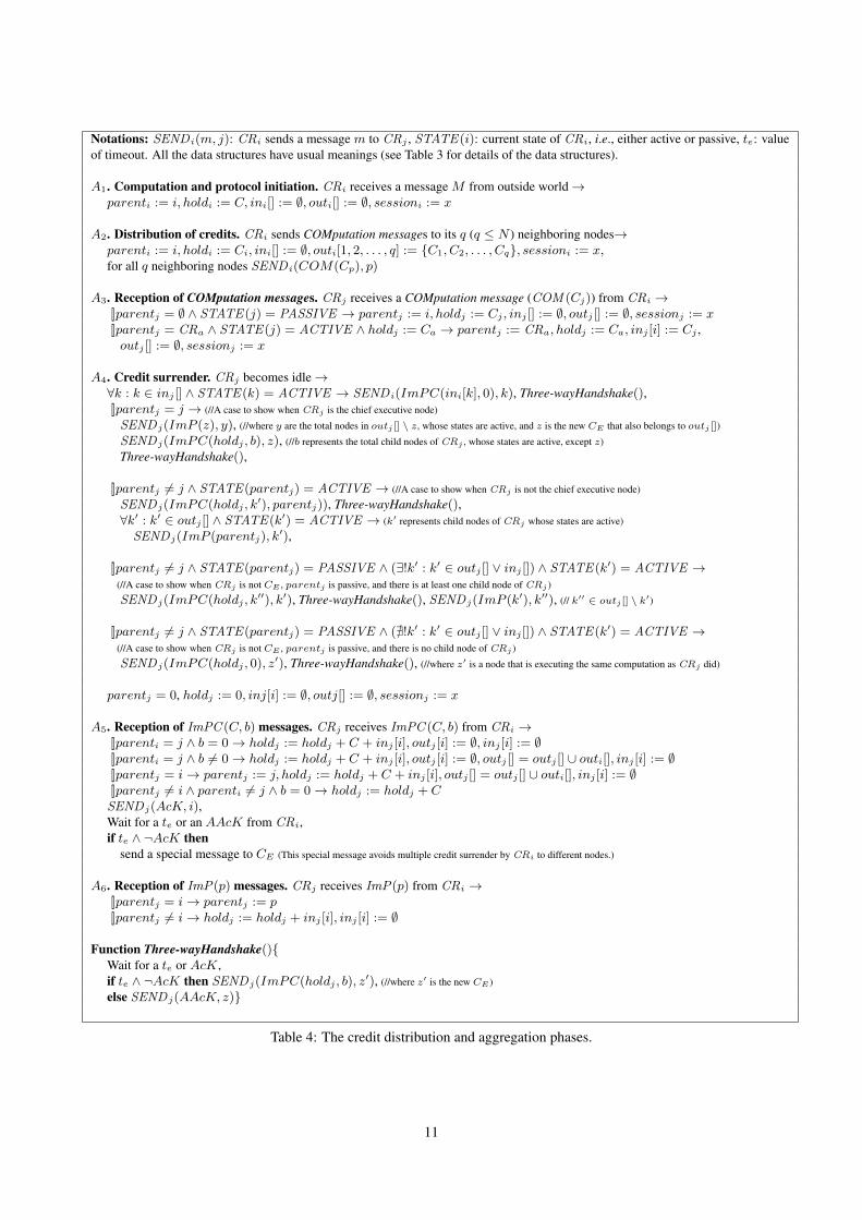
Table 4: The credit distribution and aggregation phases.
11
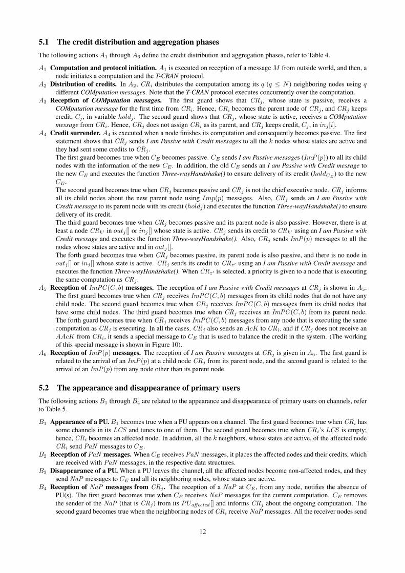
5.1 The credit distribution and aggregation phasesThe following actions A1 through A6 define the credit distribution and aggregation phases, refer to Table 4.
A1 Computation and protocol initiation. A1 is executed on reception of a message M from outside world, and then, anode initiates a computation and the T-CRAN protocol.
A2 Distribution of credits. In A2, CRi distributes the computation among its q (q ≤ N ) neighboring nodes using qdifferent COMputation messages. Note that the T-CRAN protocol executes concurrently over the computation.
A3 Reception of COMputation messages. The first guard shows that CRj , whose state is passive, receives aCOMputation message for the first time from CRi. Hence, CRi becomes the parent node of CRj , and CRj keepscredit, Cj , in variable holdj . The second guard shows that CRj , whose state is active, receives a COMputationmessage from CRi. Hence, CRj does not assign CRi as its parent, and CRj keeps credit, Cj , in inj [i].
A4 Credit surrender. A4 is executed when a node finishes its computation and consequently becomes passive. The firststatement shows that CRj sends I am Passive with Credit messages to all the k nodes whose states are active andthey had sent some credits to CRj .The first guard becomes true when CE becomes passive. CE sends I am Passive messages (ImP(p)) to all its childnodes with the information of the new CE . In addition, the old CE sends an I am Passive with Credit message tothe new CE and executes the function Three-wayHandshake() to ensure delivery of its credit (holdCE
) to the newCE .The second guard becomes true when CRj becomes passive and CRj is not the chief executive node. CRj informsall its child nodes about the new parent node using Imp(p) messages. Also, CRj sends an I am Passive withCredit message to its parent node with its credit (holdj) and executes the function Three-wayHandshake() to ensuredelivery of its credit.The third guard becomes true when CRj becomes passive and its parent node is also passive. However, there is atleast a node CRk′ in outj [] or inj [] whose state is active. CRj sends its credit to CRk′ using an I am Passive withCredit message and executes the function Three-wayHandshake(). Also, CRj sends ImP(p) messages to all thenodes whose states are active and in outj [].The forth guard becomes true when CRj becomes passive, its parent node is also passive, and there is no node inoutj [] or inj [] whose state is active. CRj sends its credit to CRz′ using an I am Passive with Credit message andexecutes the function Three-wayHandshake(). When CRz′ is selected, a priority is given to a node that is executingthe same computation as CRj .
A5 Reception of ImPC (C, b) messages. The reception of I am Passive with Credit messages at CRj is shown in A5.The first guard becomes true when CRj receives ImPC (C, b) messages from its child nodes that do not have anychild node. The second guard becomes true when CRj receives ImPC (C, b) messages from its child nodes thathave some child nodes. The third guard becomes true when CRj receives an ImPC (C, b) from its parent node.The forth guard becomes true when CRj receives ImPC (C, b) messages from any node that is executing the samecomputation as CRj is executing. In all the cases, CRj also sends an AcK to CRi, and if CRj does not receive anAAcK from CRi, it sends a special message to CE that is used to balance the credit in the system. (The workingof this special message is shown in Figure 10).
A6 Reception of ImP(p) messages. The reception of I am Passive messages at CRj is given in A6. The first guard isrelated to the arrival of an ImP(p) at a child node CRj from its parent node, and the second guard is related to thearrival of an ImP(p) from any node other than its parent node.
5.2 The appearance and disappearance of primary usersThe following actions B1 through B4 are related to the appearance and disappearance of primary users on channels, referto Table 5.
B1 Appearance of a PU. B1 becomes true when a PU appears on a channel. The first guard becomes true when CRi hassome channels in its LCS and tunes to one of them. The second guard becomes true when CRi’s LCS is empty;hence, CRi becomes an affected node. In addition, all the k neighbors, whose states are active, of the affected nodeCRi send PaN messages to CE .
B2 Reception of PaN messages. WhenCE receives PaN messages, it places the affected nodes and their credits, whichare received with PaN messages, in the respective data structures.
B3 Disappearance of a PU. When a PU leaves the channel, all the affected nodes become non-affected nodes, and theysend NaP messages to CE and all its neighboring nodes, whose states are active.
B4 Reception of NaP messages from CRj . The reception of a NaP at CE , from any node, notifies the absence ofPU(s). The first guard becomes true when CE receives NaP messages for the current computation. CE removesthe sender of the NaP (that is CRj) from its PUaffected [] and informs CRj about the ongoing computation. Thesecond guard becomes true when the neighboring nodes of CRi receive NaP messages. All the receiver nodes send
12
Notations: SEND i(m, j): CRi sends a message m to CRj , STATE(i): current state of CRi, i.e., either active or passive,Neighbor i[]: neighboring nodes of CRi that are executing the same computation as CRi. All the data structures have usual meanings(see Table 3 for details of the data structures).
B1. Appearance of a PU. A primary user appears on channels→[]LCSi 6= ∅ → CRi leaves the channel and tune to another available channel[]LCSi = ∅ → CRi becomes an affected nodes and is not allowed to send and receive messages,∀k ∈ Neighbor i[] ∧ STATE(k) = ACTIVE → SENDk(PaN,CE), where a PaN holds 〈CRi, ink[i], outk[i]〉,ink[i] = ∅, outk[i] = ∅
B2. Reception of PaN messages. CE receives a PaN that holds 〈CRi, ink[i], outk[i]〉 →PUaffectedCE
B3. Disappearance of a PU. A primary users disappear from channels→LCSi 6= ∅, SEND i(NaP,CE), ∀k ∈ Neighbor i[] ∧ STATE(k) = ACTIVE → SEND i(NaP, k)
B4. Reception of NaP messages from CRj .[]i = CE ∧ sessionCE = x ∧ STATE(CE) = ACTIVE →PUaffectedCE
[j] := ∅, C_PUaffectedCE[j] := ∅,SENDCE (m,CRj)
[]i 6= CE ∧ j ∈ Neighbor i[] ∧ sessioni = x ∧ STATE(i) = ACTIVE → SEND i(m′, CE)
Table 5: The appearance and disappearance of primary users.
C1. Global weak termination.outCE [] = ∅ ∧ inCE [] = ∅ ∧ (holdCE + C_PUaffectedCE
[] = C) ∧ STATE(CE) = PASSIVE →Announce global weak termination
C2. Global strong termination.outCE [] = ∅ ∧ inCE [] = ∅ ∧ C_PUaffectedCE
[] = ∅ ∧ holdCE = C ∧ STATE(CE) = PASSIVE →Announce global strong termination
Table 6: The termination announcement.
a special message m′ to CE that is a request to receive back the credit that they had sent earlier when CRi was anaffected node.
5.3 The termination announcementThe actions C1 and C2 represent termination detection in the networks, refer to Table 6.
C1 Global weak termination. C1 announces the global weak termination when only a single node (that is CE) has thecredit C, which was distributed at the time of computation initiation, in its holdCE
and C_PUaffected [].C2 Global strong termination. C2 announces the global strong termination when CE contains the total credit C, which
was distributed at the time of computation initiation, in its holdCE, no credit inC_PUaffected [], andCE has become
passive.
6 The Working of the T-CRAN protocol
Nodes Local Channel Sets (LCS )
1 2, 3, 5
2 3, 5, 6, 9
3 5
4 5
5 5, 7, 9
6 5, 9
Table 7: Local channel sets of all thenodes.
In Figures 6 and 7, a sample execution of the T-CRAN protocol is representedin the absence and presence of a primary user, respectively. The localchannel set for every node is given in Table 7, where boldface charactersshow the currently tuned channel at the respective nodes. Actions A1 to A6,actions B1 to B4, and actions C1, C2 are given in Tables 4, 5, and 6. Also,all the nodes are in the transmission range of each other.
In Figure 6a, cognitive radio node 1 initiates an assigned computationand the T-CRAN protocol, hence, behaves as the chief executive node, CE .Node 1 sends a COMputation message (COM (0.9)) to node 2, and node1 holds a credit value 0.1. Further, nodes 2, 3, 4, and 5 also distributethe computation with some credit values and initialize their respective datastructures (A1, A2, and first guard of A3). Note that, ini[] array of all thenodes is empty initially, and the sum of credits at nodes 1-6 equals 1.
13
2COM (0.9)
1 3
4
6
5parent1 = 1
hold1 = 0.1
in1[] = ∅out1[2] = 0.9
parent2 = 1
hold2 = 0.1
in2[] = ∅out2[3] = 0.8
parent3 = 2
hold3 = 0.1
in3[] = ∅out3[4] = 0.7
parent4 = 3
hold4 = 0.1
in4[] = ∅out4[5] = .6 parent5 = 4
hold5 = 0.2
in5[] = ∅out5[6] = 0.4
parent6 = 5
hold6 = 0.4
in6[] = ∅out6[] = ∅
COM (0.8)
COM (0.7)
COM (0.4)
COM (0.6)
1
(a)
21 3
4
6
5parent1 = 1
hold1 = 0.1
in1[] = ∅out1[2] = 0.9
parent2 = 1
hold2 = 0.1
in2[] = ∅out2[3] = 0.8
parent3 = 2
hold3 = 0.1
in3[5, 6] = {.1, .2}out3[4] = 0.7
parent4 = 3
hold4 = 0.1
in4[6] = 0.1
out4[5] = .6 parent5 = 4
hold5 = 0.1
in5[] = ∅out5[6] = 0.4
parent6 = 5
hold6 = 0.1
in6[] = 0
out6[3, 4] = {0.2, 0.1}
COM(.1)
COM(.2)
COM(.1)
1
(b)
21 3
4
6
5parent1 = 1
hold1 = 0.1
in1[] = ∅out1[2] = 0.9
parent2 = 1
hold2 = 0.1
in2[] = ∅out2[3] = 0.8
parent3 = 2
hold3 = .1 + .1 = .2
in3[5] = 0.2
out3[7] = 0.7
parent4 = 3
hold4 = 0.1 + 0.1 = 0.2
in4[6] = 0.1
out4[6] = .3 parent5 = 0
hold5 = 0
in5[] = ∅out5[] = ∅
parent6 = 4
hold6 = 0.1
in6[] = 0
out6[3, 4] = {0.2, 0.1}
ImP(4)
ImP(4)
ImPC(0.1, 1)
1
(c)
21 3
4
6
5parent1 = 1
hold1 = 0.1
in1 = ∅out1[2] = 0.9
parent2 = 1
hold2 = .1 + .2 = .3
in2[] = ∅out2[4] = 0.6
parent3 = 0
hold3 = 0
in3[] = ∅out3[] = 0
parent4 = 2
hold4 = 0.2
in4[6] = 0.1
out4[] = .3 parent5 = 0
hold5 = 0
in5[] = ∅out5[] = ∅
parent6 = 4
hold6 = 0.3
in6[] = ∅out6[4] = 0.1
ImP(2)
ImPC(0.2, 0)
ImPC(.2, 1)
1
(d)
21 3
4
6
5parent1 = 1
hold1 = 0.1
in1[] = ∅out1[2] = 0.9
parent2 = 1
hold2 = 0.3
in2 = 0
out2[4] = 0.6
parent3 = 0
hold3 = 0
in3[] = ∅out3[] = ∅
parent4 = 2
hold4 = .2 + .3 + .1 = .6
in4[] = ∅out4[] = ∅ parent5 = 0
hold5 = 0
in5[] = ∅out5[] = ∅
parent6 = 0
hold6 = 0
in6[] = ∅out6[] = ∅
ImPC (0.3, 0)
1
(e)
21 3
4
6
5parent1 = 1
hold1 = 0.1
in1[] = ∅out1[2] = 0.9
parent2 = 1
hold2 = .3 + .6 = .9
in2[] = ∅out2[] = ∅
parent3 = 0
hold3 = 0
in3[] = ∅out3[] = ∅
parent4 = 0
hold4 = 0
in4[] = ∅out4[] = ∅ parent5 = 0
hold5 = 0
in5[] = ∅out5[] = ∅
parent6 = 0
hold6 = 0
in6[] = ∅out6[] = ∅
ImPC (0.6, 0)
1
(f)
21 3
4
6
5parent1 = 0
hold1 = 0
in1[] = ∅out1[] = ∅
parent2 = 2
hold2 = .9 + .1 = 1
in2[] = ∅out2[] = ∅
parent3 = 0
hold3 = 0
in3[] = ∅out3[] = ∅
parent4 = 0
hold4 = 0
in4[] = ∅out4[] = ∅ parent5 = 0
hold5 = 0
in5[] = ∅out5[] = ∅
parent6 = 0
hold6 = 0
in6[] = ∅out6[] = ∅
ImP(∅)
1
(g)
The chief executive node
Active nodesPassive nodes
1
(h) Notations
Figure 6: The Working of the T-CRAN protocol in the absence of PUs.
In Figure 6b, node 5 sends a COMputation message (COM (0.1)) to node 3. The reception of COM (0.1) initializesin3[5] array variable at node 3 and corresponding entry in out5[3] (second guard of A3). Also, node 6 sends twoCOMputation messages to nodes 4 and 3.
In Figure 6c, node 5 becomes passive and surrenders its credit (contained in variable hold5) to its parent node 4 viaan I am Passive with Credit message, ImPC (0.1, 1) (second guard of A4). In addition, node 5 sends two I am Passivemessages (ImP(4)) to its child nodes 3 and 6. These I am Passive messages hold information of the new parent node 4.The reception of ImPC (0.1, 1) at node 4 triggers second guard of A5. The reception of ImP(4) triggers first guard ofA6 at node 6 so that node 6 assigns node 4 as its parent node, and second guard of A6 at node 3 so that node 3 holds 0.2credits. Note that we are not showing the three way handshake for clarity of figures, interested readers can look ahead toFigure 10 to see the working of the three-way handshake.
In Figure 6d, node 3 becomes passive and sends: (i) an ImPC (0.2, 0) to node 6 (the first line of A4), and node 6 holdsback 0.3 credits (first guard of A5), (ii) an ImPC (0.1, 1) to its parent node 2 (second guard of A4), and node 2 holds 0.3credits now (second guard of A5), (iii) an ImP(2) to node 4 (second guard of A4), and node 4 assigns node 2 as its parentnode (first guard of A5).
In Figure 6e, node 6 becomes passive and surrenders its credit to node 4 (second guard ofA4). Node 4 holds 0.6 creditsnow (first guard of A5). In Figure 6f, node 4 becomes passive and surrenders its credit to node 2 via an ImPC (0.6, 0)(second guard of A4).
Passive nodesActive nodes An affected node The chief executive node
1
(e) Notations
Figure 7: The Working of the T-CRAN protocol in the presence of PUs.
In Figure 6g, the chief executive node 1 becomes passive and surrenders its credit to node 2 (first guard of A4), andnode 2 now becomes the new chief executive node, holds credit 1 (third guard of A5). Once the node 2 finishes itscomputation, node 2 announces the global strong termination (according to C2).
Figure 7 shows the presence of a PU. Figure 6c, where there is no PU, turns to Figure 7a in the presence of a PU,where nodes 3 and 4 are affected nodes (second guard of B1). In Figure 7b, nodes 6 and 2 detect affected nodes 4 and 3,and inform node 1 using PaN messages (second guard of B1), and node 1 places information of the affected nodes 3, 4in the respective data structures (according to B2). In addition, node 6 surrenders its credit to node 2 (forth guard of A4).
In Figure 7c, node 2 becomes passive and surrenders its credit to node 1 (second guard of A2). Now, node 1 holdsthe credit value 1, which was distributed at the time of computation’s initiation, in hold1 and C_PUaffected [], and thiscondition is sufficient to announce the global weak termination after a timeout (according toC1). In Figure 7d, the primaryuser disappears, and nodes 3, 4 inform node 1 (CE) and ask about the ongoing computation (according to B3). Node 1informs them and deletes their entry from PUaffected and C_PUaffected [], and then, the sum of credits at node 1, 3, and 4equal to 1.
7 ConclusionA termination detection protocol, T-CRAN, for an asynchronous multi-hop cognitive radio networks is presented. TheT-CRAN protocol is capable enough to work on heterogeneous channels, and it can also handle multiple computationssimultaneously. The T-CRAN protocol is based on credit distribution and aggregation approach. The proposed protocoluses a new kind of logical structure, called the virtual tree-like structure. In the virtual tree-like structure, a node maysurrender its credit to any node (not necessarily to its parent node) that is executing the identical computation. This creditsurrender approach significantly reduces the waiting time to announce termination. Further, it is not mandatory for theinitiator of the protocol (i.e., the first root node of the virtual tree-like structure) to stay involved until the terminationof the computation. Hence, the protocol may witness different root nodes at different time instants, during the course oftermination announcement.
The proposed protocol can also be implemented in dynamic networks, e.g., cellular, mobile ad hoc networks, andvehicular ad hoc networks. The proposed virtual tree-like structure is also able to decrease the waiting time to announcetermination in dynamic networks, which is a desirable requirement in dynamic networks, due to its flexible credit surrenderapproach. Moreover, the virtual tree-like structure can substitute the conventional tree structures in various distributedcomputations, e.g., snapshot, global-state, leader election, message ordering, and group communication.
15
AcknowledgementsAuthors thank anonymous referees for detailed comments that helped to improve the quality of the paper.
References[1] Available at: http://research.microsoft.com/en-us/projects/spectrum/fcc_dynamic_
spectrum_access_noi_comments.pdf.[2] M. K. Aguilera, W. Chen, and S. Toueg. Failure detection and consensus in the crash-recovery model. Distributed
Computing, 13(2):99–125, 2000.[3] I. Akyildiz, W.-Y. Lee, M. C. Vuran, and S. Mohanty. A survey on spectrum management in cognitive radio networks.
Communications Magazine, IEEE, 46(4):40–48, April 2008.[4] I. F. Akyildiz, W.-Y. Lee, and K. R. Chowdhury. CRAHNs: Cognitive radio ad hoc networks. Ad Hoc Networks,
7(5):810–836, 2009.[5] I. F. Akyildiz, W.-Y. Lee, M. C. Vuran, and S. Mohanty. Next generation/dynamic spectrum access/cognitive radio
wireless networks: A survey. Computer Networks, 50(13):2127–2159, 2006.[6] T. Bansal, N. Mittal, and S. Venkatesan. Leader election algorithms for multi-channel wireless networks. In WASA,
pages 310–321, 2008.[7] D. Cabric, S. Mishra, and R. Brodersen. Implementation issues in spectrum sensing for cognitive radios. In Signals,
systems and computers, 2004. Conference record of the thirty-eighth Asilomar conference on, volume 1, pages772–776, 2004.
[8] M. Cesana, F. Cuomo, and E. Ekici. Routing in cognitive radio networks: Challenges and solutions. Ad HocNetworks, 9(3):228–248, 2011.
[9] S. Chandrasekaran and S. Venkatesan. A message-optimal algorithm for distributed termination detection. J. ParallelDistrib. Comput., 8(3):245–252, 1990.
[10] R. F. DeMara, Y. Tseng, and A. Ejnioui. Tiered algorithm for distributed process quiescence and terminationdetection. IEEE Trans. Parallel Distrib. Syst., 18(11):1529–1538, 2007.
[11] E. W. Dijkstra and C. S. Scholten. Termination detection for diffusing computations. Information Processing Letters,11(1):1–4, 1980.
[12] S. Dolev, S. Dubois, M. Potop-Butucaru, and S. Tixeuil. Stabilizing data-link over non-FIFO channels with optimalfault-resilience. volume 111, pages 912–920, 2011.
[13] K. Erciyes and G. Marshall. A cluster based hierarchical routing protocol for mobile networks. In ComputationalScience and Its Applications–ICCSA 2004, pages 528–537. Springer, 2004.
[14] Federal Communications Commission, 445 12th Street, SW Washington, DC 20554. MOBILE BROADBAND: THEBENEFITS OF ADDITIONAL SPECTRUM, OCTOBER 2010.
[15] M. J. Fischer, N. A. Lynch, and M. Paterson. Impossibility of distributed consensus with one faulty process. J. ACM,32(2):374–382, 1985.
[16] C. Fortuna and M. Mohorcic. Trends in the development of communication networks: Cognitive networks.Computer Networks, 53(9):1354–1376, 2009.
[17] N. Francez. Distributed termination. ACM Trans. Program. Lang. Syst., 2(1):42–55, Jan. 1980.[18] S. Ghosh. Distributed Systems: An Algorithmic Approach. Chapman & Hall/CRC Computer & Information Science
Series. Taylor & Francis, 2010.[19] E. Godard, Y. Métivier, M. Mosbah, and A. Sellami. Termination detection of distributed algorithms by graph
relabelling systems. In ICGT, pages 106–119, 2002.[20] S. Haykin. Cognitive radio: brain-empowered wireless communications. Selected Areas in Communications, IEEE
Journal on, 23(2):201–220, 2005.[21] E. Hossain, D. Niyato, and Z. Han. Dynamic spectrum access and management in cognitive radio networks.
Cambridge University Press, 2009.[22] S.-T. Huang. Detecting termination of distributed computations by external agents. In ICDCS, pages 79–84, 1989.[23] S.-T. Huang and P.-W. Kao. Detecting termination of distributed computations by external agents. J. Inf. Sci. Eng.,
7(2):187–201, 1991.[24] P. Johnson and N. Mittal. A distributed termination detection algorithm for dynamic asynchronous systems. In
ICDCS, pages 343–351, 2009.[25] S. Katiyar and S. Karmakar. A simple scheme for termination detection in delay tolerant networks. In ICCSN, pages
478–482, 2011.[26] A. D. Kshemkalyani and M. Singhal. Distributed Computing: Principles, Algorithms, and Systems. Cambridge
University Press, New York, NY, USA, 1 edition, 2008.
[27] H. Kurian, A. Rakshit, and G. Singh. Detecting termination in pervasive sensor networks. In ISADS, pages 323–332,2009.
[28] A. Liotta. The cognitive NET is coming. Spectrum, IEEE, 50(8):26–31, August 2013.[29] Q. Mahmoud. Cognitive Networks: Towards Self-Aware Networks. Wiley-Interscience, 2007.[30] J. Matocha and T. Camp. A taxonomy of distributed termination detection algorithms. Journal of Systems and
Software, 43(3):207–221, 1998.[31] F. Mattern. Global quiescence detection based on credit distribution and recovery. Inf. Process. Lett., 30(4):195–200,
1989.[32] J. Misra and K. M. Chandy. Termination detection of diffusing computations in communicating sequential processes.
ACM Trans. Program. Lang. Syst., 4(1):37–43, 1982.[33] N. Mittal, F. C. Freiling, S. Venkatesan, and L. D. Penso. On termination detection in crash-prone distributed systems
with failure detectors. J. Parallel Distrib. Comput., 68(6):855–875, 2008.[34] N. Mittal, S. Krishnamurthy, R. Chandrasekaran, S. Venkatesan, and Y. Zeng. On neighbor discovery in cognitive
radio networks. J. Parallel Distrib. Comput., 69(7):623–637, 2009.[35] S. Sharma and A. K. Singh. On detecting termination in cognitive radio networks. In PRDC, pages 71–78, 2011.[36] A. K. Singh and S. Sharma. Elite leader finding algorithm for MANETs. In ISPDC, pages 125–132, 2011.[37] R. W. Topor. Termination detection for distributed computations. Inf. Process. Lett., 18(1):33–36, 1984.[38] Y.-C. Tseng. Detecting termination by weight-throwing in a faulty distributed system. J. Parallel Distrib. Comput.,
25(1):7–15, 1995.[39] Y.-C. Tseng and C.-C. Tan. Termination detection protocols for mobile distributed systems. IEEE Trans. Parallel
Distrib. Syst., 12(6):558–566, 2001.[40] R. Urgaonkar and M. J. Neely. Opportunistic scheduling with reliability guarantees in cognitive radio networks.
IEEE Trans. Mob. Comput., 8(6):766–777, 2009.[41] B. Wang and K. Liu. Advances in cognitive radio networks: A survey. Selected Topics in Signal Processing, IEEE
Journal of, 5(1):5–23, 2011.[42] J. Wang, M. Ghosh, and K. S. Challapali. Emerging cognitive radio applications: A survey. IEEE Communications
Magazine, 49(3):74–81, 2011.[43] W. Wang, H. Li, Y. L. Sun, and Z. Han. Securing collaborative spectrum sensing against untrustworthy secondary
users in cognitive radio networks. EURASIP J. Adv. Sig. Proc., 2010, 2010.[44] A. M. Wyglinski, M. Nekovee, and Y. T. Hou. Cognitive Radio Communications and Networks: Principles and
Practice. Academic Press, 2009.[45] Y. Zeng, Y.-C. Liang, A. T. Hoang, and R. Zhang. A review on spectrum sensing for cognitive radio: Challenges
and solutions. EURASIP J. Adv. Sig. Proc., 2010, 2010.[46] Y. Zeng, N. Mittal, S. Venkatesan, and R. Chandrasekaran. Fast neighbor discovery with lightweight termination
detection in heterogeneous cognitive radio networks. In ISPDC, pages 149–156, 2010.
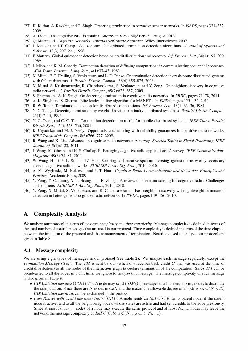
A Complexity AnalysisWe analyze our protocol in terms of message complexity and time complexity. Message complexity is defined in terms ofthe total number of control messages that are used in our protocol. Time complexity is defined in terms of the time elapsedbetween the initiation of the protocol and the announcement of termination. Notations used to analyze our protocol aregiven in Table 8.
A.1 Message complexityWe are using eight types of messages in our protocol (see Table 2). We analyze each message separately, except theTermination Message (TM ). The TM is sent by CE (when CE receives back credit C that was used at the time ofcredit distribution) to all the nodes of the interaction graph to declare termination of the computation. Since TM can bebroadcasted to all the nodes in a unit time, we ignore to analyze this message. The message complexity of each messageis also given in Table 9.• COMputation message (COM (C)): A node may send COM (C) messages to all its neighboring nodes to distribute
the computation. Since there are N nodes in CRN and the maximum allowable degree of a node is4, O(N ×4)COMputation messages can be exchanged in the protocol.
• I am Passive with Credit message (ImPC (C, b)): A node sends an ImPC (C, b) to its parent node, if the parentnode is active, and to all the neighboring nodes, whose states are active and had sent credits to the node previously.Since at most Nneighbor nodes of a node may execute the same protocol and at most Nleave nodes may leave thenetwork, the message complexity of ImPC (C, b) is O(Nneighbor ×Nleave).
17
Notations Description
N The total number of the cognitive radio nodes in the network.
4 Maximum degree of a nodes in the network.
Height Maximum height of the virtual tree-like structure.
Nleave The total number of nodes that can leave the network during the protocol execution.
Naffected Maximum number of nodes that are affected during the protocol execution.
Nneighbor Maximum number of neighboring nodes that are executing the same computation.
Table 8: Notations used in the complexity analysis of the T-CRAN protocol.
Messages Complexity
COMputation message O(N ×4)
I am Passive with Credit message O(Nneighbor ×Nleave)
I am Passive message O((Nneighbor − 1)×Nleave)
Primary user affected Nodes message O(Nneighbor ×Naffected )
Nodes released by Primary user message O((Nneighbor + 1)×Naffected )
AcKnowledgement message O(Nneighbor ×Nleave)
Acknowledgement of AcK message O(Nneighbor ×Nleave)
Table 9: Message complexity of the T-CRAN protocol.
• I am Passive message (ImP(p)): A node sends ImP(p) messages to all its child nodes, whose states are active.Since a single node sends at most (Nneighbor − 1) ImP(p) messages and at most Nleave nodes may leave thenetwork, the message complexity of ImP(p) is O((Nneighbor − 1)×Nleave).
• AcKnowledgement message (AcK) and Acknowledgement of AcK message (AAcK): An AcK and an AAcKis generated in response to an ImPC (C, b); hence, O(Nneighbor × Nleave) AcK and AAcK messages can begenerated in the protocol.
We also present the total number of non-control messages, as follows:• Primary user affected Nodes message (PaN ): All the neighboring nodes of an affected node, whose states are
active, send PaN messages to CE . Since at most Nneighbor nodes of at most Naffected nodes may send PaNmessages, the message complexity of PaN is O(Nneighbor ×Naffected).
• Nodes released by Primary user message (NaP ): After recovery, the affected node sends PaN messages to itsneighboring node and CE . Since at most Nneighbor and CE receive PaN messages from Naffected nodes, themessage complexity of NaP is O((Nneighbor + 1)×Naffected).
A.2 Time complexityThere are three types of nodes in the network: (i) nodes whose out[] = ∅, (ii) CE , and (iii) node whose out[] 6= ∅ orin[] 6= ∅ and they are not the chief executive node. The nodes with out[] = ∅ may leave the network when they finishtheir computation by sending ImPC (C, b) messages to at mostNneighbor nodes. Similarly, CE may also leave by sendingImPC (C, b) or ImP(p) messages to at mostNneighbor nodes. Also, the node other thanCE that has out[] 6= ∅ or in[] 6= ∅exchanges at most Nneighbor messages before leaving the network. We assume that all the messages are delivered in aunit time. Hence, in the failure-free network, all the nodes of the network take O(Height) time to leave the networkthat results in global strong termination declaration. However, the presence of PUs increases termination latency. In suchscenarios, the declaration of global weak termination would be delayed according to the value of timeout.
B Correctness ProofWe first provide the system invariants; afterward, we prove the safety and liveness properties of the T-CRAN protocol. Wealso prove an impossibility result that the appearance of a primary user on a single channel may defy termination forever.
B.1 System invariantsInvariant 1 Let, STATE (i) represents the state of CRi, which may be active or passive. For CRi, holdi = 0 indicatespassive state of CRi and vice versa. Also, holdi 6= 0 indicates active state of CRi and vice versa.
∀i : holdi = 0⇔ STATE (i) = PASSIVE , ∀i : holdi 6= 0⇔ STATE (i) = ACTIVE
Invariant 2 In CRN, the sum of credits at the nodes and credits associated with in-transit messages must be C.
where, m can be a COMputation message or an I am Passive with Credit message.
Invariant 3 The global strong termination can be declared, in case, there is no PUs in CRN. Thus, only a single CRi
contains credit value C if the node is the chief executive node and there is no in-transit message, m, in the global channelset, GCS .
∃i,∀j : j ∈ n, i ∈ j :: holdi = C ⇔ i = CE ∧ STATE (j) = PASSIVE ∧m /∈ GCS
Invariant 4 For the global weak termination, the total credit value C is known to CE . However, C is distributed amongCE and the affected nodes.
outCE[] = ∅ ∧ inCE
[] = ∅ ∧ (holdCE+ C_PUaffectedCE
[] = C)
B.2 Safety propertyThe safety property ensures that in no case a node other than CE announces termination if the computation has indeedterminated. In order to prove the safety property, we consider all the possible cases that may negate the system invariantsand violate the safety requirements, as follows:
1. The incorrect recovery from any failure (e.g., the appearance of PUs, mobility, and crash) may temporarily falsifyInvariants 2, 3, and 4. Lemma 1 and Lemma 2 assert that the incorrect recovery from any failure does not violatethe safety requirements.
2. Before reaching the actual termination, the value of holdCE= C or holdCE
> C, then Invariant 3 or Invariant 4are violated. Lemma 3 and Lemma 4 ensure that CE holds credit C in case of global strong termination and thecredit less than C in case of global weak termination.
The proofs of Lemmas 1- 4 guarantee the safety requirements of the T-CRAN protocol. The following Lemma 1 andLemma 2 prove that the nodes do not violate the safety requirements on their recovery.
Lemma 1 The reception of stale messages, m〈session,∗〉, at the nodes do not increase credit value C forever, whichviolates the safety requirements of the T-CRAN protocol.
Proof. Assume that on recovery,6 CRi receives stale messages, m〈session,∗〉 = m〈x,∗〉, from unreliable channels or otherrecovered nodes. The reception of m〈x,∗〉 at CRi is able to execute the computation and transmission of m〈x,∗〉, in casesessioni ≤ x. For the contrary, we assume that a node receives a stale message, m〈x,∗〉, executes the computation andpropagatesm〈x,∗〉. We now prove that the reception of stale messages does not violate the safety requirements, as follows:
CRi can further distribute the computation or surrender credit after completion of its computation among itsneighboring nodes, in response to m〈x,∗〉. The neighboring node CRj of CRi may be a recovered node or unawareof the just terminated computation whose session = x. Hence, the recipient CRj can also behave similar to CRi.However, one of the nodes in the network or CE terminates the flow of m〈x,∗〉 due to sessionCE
6= x (Action A4 inTable 4).
Hence, the system maintains Invariant 2, and once the credit is greater than C, it is detected by some nodes; thus stalemessages cannot violate the safety requirements of the T-CRAN protocol. �
The following assumptions help us to prove Lemma 2: we use four different time instants α, β, γ, and δ such thatα < β < γ (all the other lemmas will also use these time instances) and three nodes CRi, CRj and CRk that areneighbors of each other. CRi initiates the T-CRAN protocol at time α among CRj and CRk with session = x. Under afault-free scenario, at time γ, CRi announces global strong termination. Suppose, CRk becomes an-affected node at timeβ.
Lemma 2 On recovery, the initiation of a node in active or passive state does not result in false termination.
Proof. We first mention all the possible situations that may exist at the time of transition of a node from an affectednode to a non-affected node or vice versa, which may announce false termination. Afterward, we prove that none of thesesituations can lead to the violation of the safety requirements in our protocol.
CASE 1 CRk is not able to recover, i.e., CRk is an affected node for a very long time.CASE 2 CRk recovers, due to availability of another available channel in LCSk or disappearance of the PU, at time δ,
where δ < γ.6We assume that the recovery process takes non-zero time.
19
CE
COM
i
kj
COM
COM
1
(a) At time α
CE
i
kj
1
(b) At time β
CE
i
kj
1
(c) At time γ
Passive nodes
Active nodes
An affected node
1
(d) Notations
Figure 8: Illustration for the proof of Lemma 2.
i
1
(a) At time α
COM(Cj)
i
j
1
(b) At time β
COM(Ci)
i
j
1
(c)
i
j
holdi = C
1
(d) At time γ
Figure 9: Illustration for the proof of Lemma 3.
CASE 3 CRk recovers, due to availability of another available channel in LCSk or disappearance of the PU, at time δ,where δ > γ.
The CASE 1 results in permanent failure of CRk, i.e., CRk is a crashed node. Hence, the global strong termination isdefied forever, and the protocol announces global weak termination of the computation at CRi and CRj .
The CASE 2 results in the global strong termination, when sessionk = sessionCE(= sessioni) at the time of
recovery of CRk in active state. However, passive state of the node is irrelevant here, because passive state of CRk
indicates that CRk has already surrendered its credit before the transition from a non-affected node to an affection node.In CASE 3, CE has already declared global weak termination before recovery of CRk. Specifically, CASE 1 and
CASE 3 are almost similar and do not affect CE , because sessionCE6= sessionk. In addition, the recovery of CRk in
active state may cause to propagate messages, m〈session,∗〉 = m〈x,∗〉, to CRi or CRj . However, according to Lemma 1,CRi, which is CE , discard m〈x,∗〉 eventually because seesionCE
6= x. (For a better understanding, readers may refer toFigure 8)
Thus, on recovery, the nodes’ state do not affect the correct termination, and Invariants 3 and 4 holds. �
The credit aggregated at CE never ever becomes equal to C before the global strong termination is reached. This factcan be justified with the help of Lemma 3 and Lemma 4, as follows:
Lemma 3 Under no condition the credit aggregated at CE equals to C except in the case of global strong termination.
Proof. Suppose, only two processors CRi and CRj are executing a computation, and CRi is the chief executive node.CRi sends credit Cj to CRj , and again, CRj sends credit Ci to CRi. Thus, according to Invariant 2, the followingequation 2 holds true:
Suppose at time α, CRi becomes active. Thus, SEND i(COM(Cj), j) = 0. However, at time β, the followingequation 3 holds true:
holdi + SEND i(COM(Cj), j) + holdj = C (3)
The above equation 3 indicates credit distribution using a COMputation message from CRi to CRj . However, once CRj
receives the COMputation message, then SEND i(COM(Cj), j) = 0. Thus, the following equation 4 holds ture:
holdi + holdj = C (4)
Assume the contrary, at a later time γ, holdi = C, and CRi, which is the chief executive node, declares globalstrong termination, while STATE (CRi) = STATE (CRj) = ACTIVE . It is possible only when CRi and CRj are two
processes at an identical node, i.e., CRi = CRj . However, the chief executive node, CRi, never declares global strongtermination despite holdi = C, unless STATE (CRi) = PASSIVE (Action C2, Table 6). Therefore, the protocol neverdeclares termination unless all the nodes are passive, and holdCE
= C. (For a better understanding, readers may refer toFigure 9.)
The above proof can be generalized for any number of participating nodes. Thus, the protocol always aggregatescorrect credit in case of the global strong termination. �
The credit aggregated at CE never becomes (i) greater than or equals to C, in case of the global weak termination and,(ii) greater than C, in case of the global strong termination. We call the wrong credit aggregation when holdCE
≥ C incase of the global weak termination and holdCE
> C in case of the global strong termination. Both the above facts areproved by Lemma 4, as follows:
Lemma 4 No message transmission ever results in wrong credit aggregation in weak or strong termination declaration.
Proof. The conditions that may lead to wrong credit collection at CE are the aggregation of an identical credit at morethan one node, and the stale messages in the network. However, we have proved that the stale messages are eventuallydiscarded (Lemma 1). Hence, we consider the aggregation of an identical credit at more than one node.
We first present a scenario that may lead to multiple times credit surrender of an identical credit at two different nodes.Note that duplicate message reception at a node is handled in the protocol; hence, we not consider it. We present twopossible cases that may lead to wrong credit aggregation, and following that we prove by contradiction that these casesnever arise in the protocol.
Suppose, an ongoing computation with session = x, where CRi completes its computation and sends anImPC (holdi, b) to CRj . In the meantime, suppose CRj becomes an affected or a failed node (see Failure Model,Section 2). Thus, CRj cannot send an AcK to CRi. Due to non-reception of an AcK from CRj , CRi sends anImPC (holdi, b) to another node, say CRk. However, the recovery of CRj and the reception of an ImPC (holdi, b) atCRj signify that holdi is surrendered at two different nodes. However, in the protocol, there are only two possible casesof the imperfect credit surrender, as follows:
CASE 1 CRj is an affected or a failed node after sending anAcK to CRi, and CRi is already an affected or a failed nodeafter the transmission of an ImPC (holdi, b).
CASE 2 CRi sends an ImPC (holdi, b) to CRj , and due to the absence of an AcK from CRj , CRi sends anImPC (holdi, b) to CRk. After sending ImPC (holdi, b) messages to two different nodes, CRi becomes an affectednode. Also, CRj receives the ImPC (holdi, b).
The reception of an AcK and an AAcK is assumed to be an atomic operation, i.e., CRj is not allowed to move toa different location before the reception of an AAcK or a timeout, and also, CRj receives an AAcK in the presence ofPUs. Therefore, CASE 1 never holds true.
The CASE 2 is essentially an outcome of the CASE 1. CRj receives an ImPC (holdi, b) and sends anAcK to CRi. Asthe affected node CRi cannot receive an AcK from CRj ; after a timeout value, CRj recognizes that CRi is an affectednode. Thus, CRj sends a special message, m, with credit holdi, to CE . Eventually, CE subtracts holdi from holdCE
.
21
On recovery, CRi again surrender its credit (Lemma 2). On the other hand, CRi receives an AcK from CRj though ithas already surrendered its credit to CRk earlier; thus, CRi behaves as an affected node. Therefore, the credit of CRi
remains a constant in the network. (For a better understanding, readers may refer to Figure 10.)Thus, Invariants 3 and 4 are preserved, and an imperfect surrender of a credit is infeasible in the T-CRAN protocol. �
B.3 Liveness propertyIn the T-CRAN protocol, CE eventually announces termination in finite time. In order to prove the liveness, we show:
1. The virtual tree-like structure does not grow infinitely.2. The height of the virtual tree-like structure eventually reduces, to (i) one, in case of the global strong termination,
and (ii) two, in case of the global weak termination.
We show that the virtual tree-like structure grows and has a finite height. CE , i.e., the root of the virtual tree-likestructure, expands the computation among N nodes (using A2 and A3, Table 4). The distribution of the computation andcredit increases the height of the virtual tree-like structure, and the maximum height of the virtual tree-like structure canbe N . However, the joining of new nodes in the network during the computation execution may increase the total numberof CRs and the maximum height toN +k, k > 0. In this manner, the virtual tree-like structure grows infinitely. However,once the nodes stop to join the network, then the virtual tree-like structure does not grow infinitely.
We now show that the height of the virtual tree-like structure eventually reduces. The nodes are not allowed to delaythe computation for an infinite time. Hence, once all the nodes (except CE), whose heights are identical, complete theircomputation, they send ImPC (C, b) and ImP(p) messages to their parent node or to any number of neighboring nodes,if they are active (Action A4, Table 4). Thus, the transmission of ImPC (C, b) and ImP(p) messages by all the nodes(except CE), whose heights are identical (not necessary at an identical time), results in reduction of the height of thevirtual tree-like structure by at least 1.
We now show that when the virtual tree-like structure has height 1 after credit aggregation, it is a sufficient conditionto announce the global strong termination. From the previous facts, it is clear that the height of the virtual tree-likestructure reduces by at least 1 when all the nodes (exceptCE), whose heights are identical, send ImPC (C, b) and ImP(p)messages. Hence, when all the nodes of all the height levels (except CE), send ImPC (C, b) and ImP(p) messages thatresult in the height of the virtual tree-like structure to be 1, eventually, and only a single node, CE , holds the completecredit (that is equal to the credit that was distributed at the time of initiation). This fact is enough to show that at the timeof the global strong termination the virtual tree-like structure has height 1.
We now show that when the virtual tree-like structure has height 2 after credit aggregation, it is a sufficient conditionto announce the global weak termination. From the previous facts, it is clear that the height of the virtual tree-like structurereduces when the non-affected nodes sends ImPC (C, b) and ImP(p) messages. In addition, only a single non-affectednode, CE , holds the credit of all the non-affected nodes eventually. Since the affected nodes cannot send ImPC (C, b)and ImP(p) messages, the network is divided into two partitions as: CRNP and CRNN (Figure 5). Hence, the virtualtree-like structure has height 2, and it is sufficient for the global weak termination.
B.4 The impossibility of terminationWe provide an abstract view to show the impossibility of the global strong termination in the presence of a single primaryuser. By this abstract view, it will be clear that the appearance of a primary user is difficult to handle than mobility andcrash of nodes. (Note that in a purely asynchronous CRN, the global strong termination is impossible [15] to detect evenif a single primary user exists in the network.)
We consider a CRN as a connected communication graph that has nodes np, np1, . . . , npi, nq, nq1, . . . , nqj ,nr, nr1, . . . , nrk, ns, ns1, . . . , nsl; and no node is assumed to be special. (The node ids are selected in a special wayto help readers to understand the abstract view, which will be clear soon.) Also, we assume four PUs, namely PUp, PUq ,PUr, and PUs that affect all the nodes. The virtual clustering is performed by considering np, nq, nr, and ns as fixedcenters [13] (or cluster heads) that partition the communication graph into four virtual clusters, say Cp, Cq, Cr, and Cs,see Figure 11a.
Now, assume that three PUs, namely PUp, PUq , and PUr, disappear from the network. Thus, the nodes, namelynp, np1, . . . , npi, nq, nq1, . . . , nqj , nr, nr1, . . . , nrk, become non-affected nodes, Figure 11b. All the non-affected nodesof each cluster send ImPC (C, b) messages to the respective cluster heads. Hence, each cluster head holds a terminationreport (or credit) of its cluster, namely np has TRCp, nq has TRCq , and nr has TRCr, Figure 11c.
In order to announce the global strong (or weak) termination in the network, it is required to aggregate all thetermination reports (or credits) of each cluster head. Thus, np sends TRCp to its neighboring virtual cluster head nq, andnq aggregates the received credit as: TRCpCq = TRCp ∪ TRCq , Figure 11d. This state of the network is equivalent
22
PUp
PUr
PUq
PUsnpi Cp
npnp1
ns1 Csns1
nsl ns
nq1 Cqnqj
nq
nr
nr1 Cr
nrk12
34
1
(a)
PUsnpi
npnp1
ns1ns1
nsl ns
nq1nqj
nq
nr
nr1
nrk12
34
1
(b)
PUsnpi
npnp1
ns1ns1
nsl ns
nq1nqj
nq
nr
nr1
nrk12
34
TRCp
TRCq
TRCr
1
(c)
PUsnpi
npnp1
ns1ns1
nsl ns
nq1nqj
nq
nr TRCr
nr1
nrk12
34
TRCpTRCpCqTRCp
1
(d)
PUsnpi
npnp1
ns1ns1
nsl ns
nq1nqj
nq
nr
nr1
nrk12
34 TRCpCqCr
TRCpCq
1
(e)
PUs
ns1ns1
nsl ns nr TRCpCqCr
Broken link due to a primary user
1
(f)
Passive nodesActive nodes An affected node Termination report
1
(g) Notations
Figure 11: Illustrating the impossibility of termination in cognitive radio networks.
Connected CRNVirtual partition and merge approach
Single PU appearancePartitioned CRN
1
Figure 12: The virtual partition and merge approach.
23
to the virtual merging of both the virtual clusters Cp and Cq in one virtual cluster, where Cq is a virtual cluster head.Similarly, TRCpCq is aggregated with TRCr at nr as: TRCpCqCr = TRCpCq ∪ TRCr, Figure 11e.
Since a PU, PUs, persists in the network and ns, ns1, . . . , nsl are affected node, an aggregated termination report (orcredit) of the network cannot be generated. The network is now partitioned into two parts, where the first part holds creditTRCpCqCr at nr and the remaining credit is distributed among the affected nodes, ns, ns1, . . . , nsl. This state of thenetwork is equivalent to the virtual partitioning of the network into two virtual clusters: one virtual cluster, where Cp, Cq ,and Cr are virtually merged and nr is a virtual cluster head, and the another virtual cluster Cs with ns as a virtual clusterhead, Figure 11f.
Therefore, it is shown that the existence of a single PU results in two isolated sub-networks, which is sufficient toprevent the protocol to announce the global termination. Without loss of generality, the above virtual partition-mergetechnique (Figure 12) can be applied to a network of arbitrary size and arbitrary number of PUs.
Note: When the chief executive node, CE , becomes an affected node, neither strong nor weak termination detectionis possible.
Authors’ BiographiesShantanu Sharma is a PhD student at Ben-Gurion University of the Negev, Israel. He received his MTech degree inComputer Science from National Institute of Technology, Kurukshetra, India, in 2011. His research interests includedesigning models for MapReduce computations, distributed algorithms, and mobile computing.
Awadhesh Kumar Singh received his BTech degree in Computer Science from Gorakhpur University, Gorakhpur, India,in 1988, and his MTech and PhD degrees in Computer Science from Jadavpur University, Kolkata, India, in 1998 and 2004,respectively. He joined the Department of Computer Engineering at National Institute of Technology, Kurukshetra, India,in 1991, where he is Professor at present and earlier he also served as the chairman of Computer Engineering Departmentduring 2007-2009. His research interests include distributed algorithms, mobile computing, and fault tolerance.